
Abstract
The CoCrFeMnNi multi-principal element alloy (MPEA), renowned for exceptional mechanical, thermal and corrosion properties, presents challenges in cost-effective deposition. This work demonstrates a dilution-engineered Gas Tungsten Arc Welding (GTAW) in-situ alloying approach using commercially available feedstock (SS304 filler tube + elemental powders). A two-stage strategy was employed includes (1) full-factorial experimental design identifying critical heat input (H.I.c ≈ 784 J/mm) and critical dilution (Dc ≈ 23 at% Fe) and (2) powder volume (Pv) variation (20–60%) to achieve equiatomic composition. Results reveal equiatomic CoCrFeMnNi (20 at% each) achieved at optimized condition of 120 A, 100 mm/min, 30% Pv, with dominant single-phase FCC microstructure, grain refinement (30.6 ± 9.1 µm), and enhanced corrosion resistance (Ecorr = −0.34 V vs. −0.51 V for vacuum arc-melted reference). The absence of intermetallic compounds in the micro-hardness survey across interface and superior metallurgical bonding (ASTM-E290 bend test >90° without de-lamination) demonstrate the viability of commercially feasible in-situ alloying for GTAW-based MPEA coatings.
Keywords
Introduction
Multi-Principal Elemental Alloys (MPEAs) offer property combinations seldom achieved in conventional alloys.1 Their high hardness, 2 excellent wear resistance at ambient and elevated temperatures,3,4 and superior oxidation, 5 corrosion, 6 and thermal/microstructural stability 7 make them promising for surface coatings in power generation, aerospace, marine, automotive, and defense sectors. Equiatomic CoCrFeMnNi (Cantor alloy) exemplifies this potential through delivering exceptional corrosion resistance in chloride environments.8–11 Various deposition techniques have been explored, 12 with laser cladding predominance despite limited feedstock availability, 13 complex pre-processing, and high cost. 14 Arc-welding methods using commercial feedstock provide cost-effectiveness and scalability,15,16 however GTAW cladding suffers from high substrate dilution (20–50% Fe pickup), disrupting equiatomic composition and causing phase instability.17–19 Prior in-situ GTAW studies employed pre-placed powders 20 and powder preforms21,22 and multiple stranded alloy wires, 23 yet these suffer from powder handling instability (segregation, uneven melting), limited deposition rates, poor process automation, and persistent high dilution without compositional feedback.24,25
In-situ surface alloying leverages substrate dilution as an elemental source, 26 with successes in Cr, 27 N, 28 and Cu 8 modifications. Metal-cored fillers offer superior powder containment and feed consistency but remain underexplored for dilution control. 9 No systematic framework is available till date that converts GTAW Fe dilution into a predictable alloying mechanism while ensuring bonding and homogeneity.
In the present study, it is hypothesized that metal-cored fillers enable GTAW dilution engineering through element-specific dilution tracking (Di), critical thresholds (H.I.c, Dc), and powder volume (Pv) energy partitioning to harness substrate Fe as an intentional source for equiatomic CoCrFeMnNi overlays matching vacuum-melted properties. Unlike pre-placed powders (prone to segregation) or multi-wire systems (complex synchronization), metal-cored fillers provide stable powder delivery, precise Pv control, and dilution predictability. This study tests the hypothesis through (1) Di validation and threshold identification (2) Pv tuning for compositional precision (3) crystal structure analysis by XRD and microstructural analysis by SEM (4) bond strength, hardness, corrosion benchmarking.
Materials and methods
Materials design strategy
The materials selection and feedstock design were strategically developed to test the hypothesis that GTAW substrate dilution can be engineered as an intentional Fe source. Low-carbon steel (LCS) plates measuring 150 × 150 × 8 mm (Fe-0.15C-0.46Mn, ASTM A36) were selected as substrate. This simulates industrial structural steels requiring overlays while providing consistent Fe dilution. The 8 mm thickness ensures semi-infinite heat sink behavior minimizing edge effects on melt pool dynamics. Metal-cored filler tubes (5.0 mm OD) were fabricated from SS304 sheet (Fe-0.06C-20Cr-8Ni-1.2Mn, ASTM A240) with 0.05 mm wall thickness. This configuration limits filler Fe contribution while supplying essential Cr (∼20 wt %) and Ni (∼8 wt %) alongside feed stability. Trace C/S/P (≤0.045 wt %) elements were excluded from mass balance calculations due to very low wt % and low impact on phase/properties. Elemental powders (Co, Cr, Mn, Ni ≥99.5%) have enabled stoichiometric control which is unattainable with pre-alloyed wires. Powder sizes (Mn ∼500 µm, Cr ∼250 µm, Ni ∼200 µm, Co ∼1.5 µm) were chosen for optimal filling and effective melting at the given feed rates. 25 Powders were mixed for 30 min in tubular mixer, filled into U-shaped tubes and sealed (Figure 1).
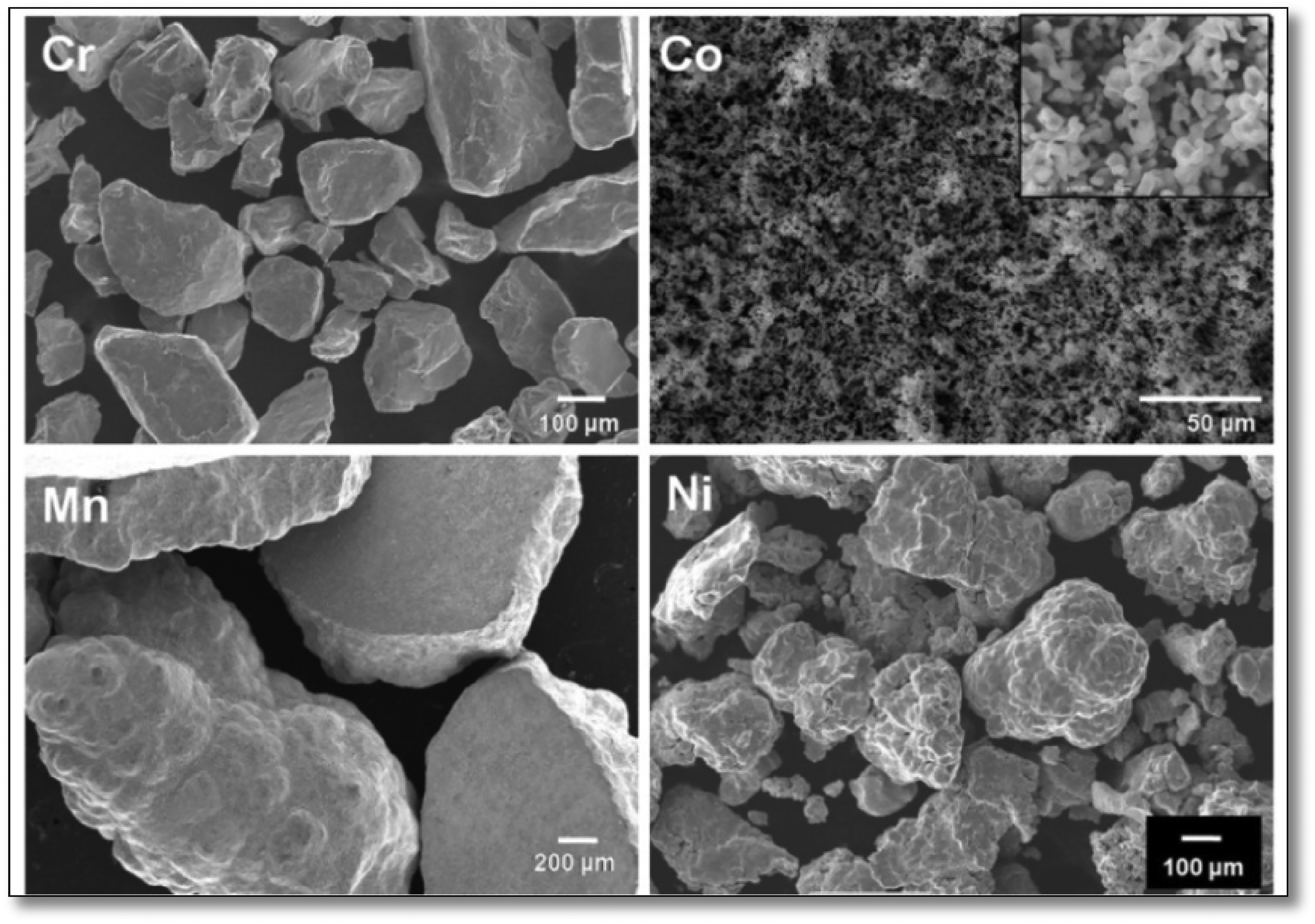
Morphology of the elemental metal powders used in the study.
The feedstock composition was engineered via mass balance for near equiatomic CoCrFeMnNi post-dilution (detailed in Table S1). Deliberately Fe-lean filler (∼10.69 at% Fe) was designed anticipating remaining 10–15 at% substrate Fe will be picked-up during the cladding process to achieve target stoichiometry. Contributions from SS304 (Cr, Ni, minor Mn) were explicitly accounted for, with other elements biased ∼22–23 at% to compensate dilution.
In-situ alloying through GTAW cladding
The GTAW cladding process schematic is shown in
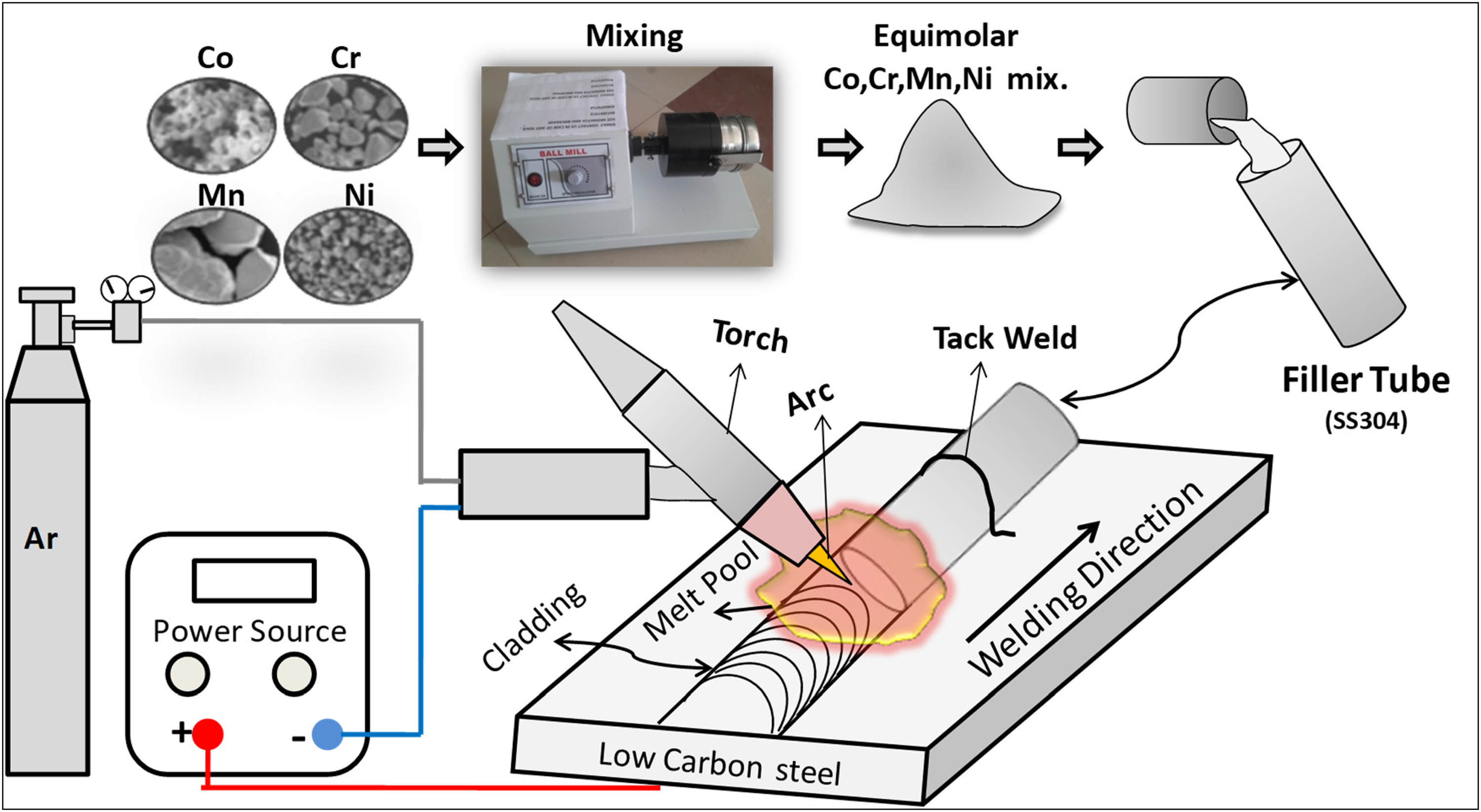
Process schematic for developing CoCrFeMnNi MPEA in-situ GTAW cladding.
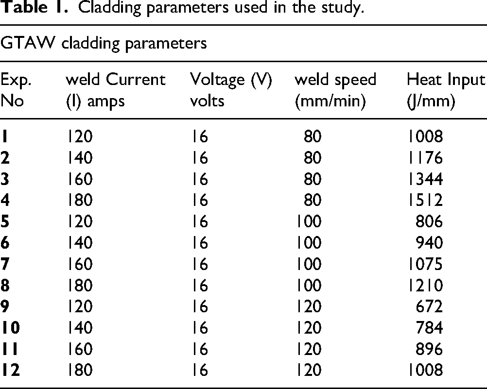
Cladding parameters used in the study.
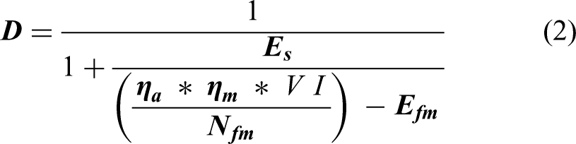
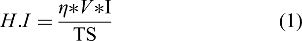
Where Es and Efm stand for melting enthalpies of substrate and filler metals respectively. ηa, ηm are arc and melting efficiencies V & I are arc voltage and weld current, respectively.
Structural characterization and property evaluation methods
Stage-2 Optimized claddings were transversely sectioned at the centerline using electro-discharge machining (EDM), minimizing thermal distortion. Samples underwent standard metallographic preparation, sequential grinding (600–2000 grit SiC), polishing (3, 1, 0.5 µm diamond suspensions), and etching (aquaregia, HNO3: HCl = 1:3, 20–30 s) to reveal microstructure. Composition and microstructure were characterized using a Carl Zeiss® Merlin Compact FEG-SEM equipped with EDS. Wide-area elemental maps (200× magnification, ≥1 mm2 area) and ten area scans assessed for homogeneity and dilution. The Conventional area based dilution calculation using eq. (3), (A is cladding area and B is penetration area) was replaced with element-specific dilution index (Di) (eq.4) as the former is unable to provide element specific dilution details and also can’t identify elements concentrating rather than diluting.
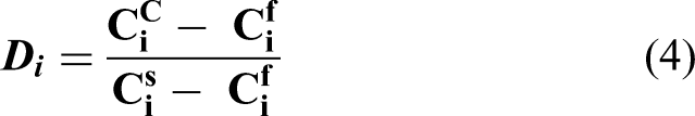
Where Di is the dilution / concentration of the ith element, CiC,Cif and Cis are the composition of ith element in cladding, filler and substrate respectively. 24 Phase identification was done by Bruker® D8 Advance XRD (Cu Kα radiation, λ = 1.5406 Å, 45 kV/40 mA, 30–100° 2θ, 0.02° step size) against ICDD standards. A reference equiatomic CoCrFeMnNi ingot was prepared through vacuum arc melting (Buhler® MAM-1, 10−5 mbar, Zr getter, five times re-melted for homogenization) for direct comparison. Mechanical properties included Vickers microhardness profiling across the cladding-substrate interface (Walter® UHL VMHT, 200 g load, 15 s dwell, 150 µm spacing) to detect intermetallic formation and hardness gradients. Interfacial integrity was evaluated by facebend testing (ASTM E290: 10 mm punch radius, 44 mm span,). Corrosion resistance was assessed via potentiodynamic polarization (PDP) on samples polished to 2400 grit. After 30 min open-circuit potential (OCP) stabilization in 3.5 wt% NaCl, scans proceeded from −1.5 to +1.0 VSCE at 1 mV/s (IVIUM® XRE potentiostat, 25°C). Corrosion current (Icorr) and potential (Ecorr) were extrapolated via Tafel analysis and corrosion rates were calculated as per Eqs.S4-S5 of the supplementary data. Tests were repeated for three times for reproducibility.
Results and discussion
The results were systematically validated for the hypothesis that substrate dilution engineering to achieve in-situ equiatomic CoCrFeMnNi cladding, through four sequential investigations: (1) establishing process-dilution relationships through Stage-1 parametric study, identifying critical heat input (H.I.c) and critical dilution (Dc) thresholds governing the balling-to-bonding transition (2) demonstrating compositional precision via Stage 2 powder volume (Pv) manipulation and energy partitioning control (3) examine single-phase FCC formation and microstructural evolution and (4) benchmarking hardness, bond-integrity and corrosion performance against vacuum-melted (VM) reference.
Stage I: process window and critical thresholds identification
Dilution trends and arc physics interpretation
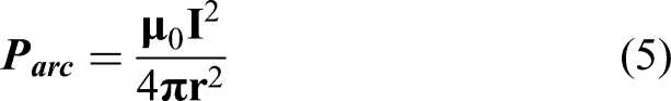
Fe dilution and cladding compositions under the tested conditions (Table 1) were determined employing wide-area energy-dispersive spectroscopy (EDS). Average Fe dilution (at%), standard deviations, and bonding quality are presented in Figure 3. Fe dilution increased systematically with weld current and decreased with traverse speed, as evidenced by the contraction of the Fe compositional domain from experiment 12 to 1 (Figure 3). The weld current dependence originates from four interdependent arc physics mechanisms. Primarily, arc pressure varies proportionally to the square of the weld current, as formulated in Lancaster's electromagnetic force model
30
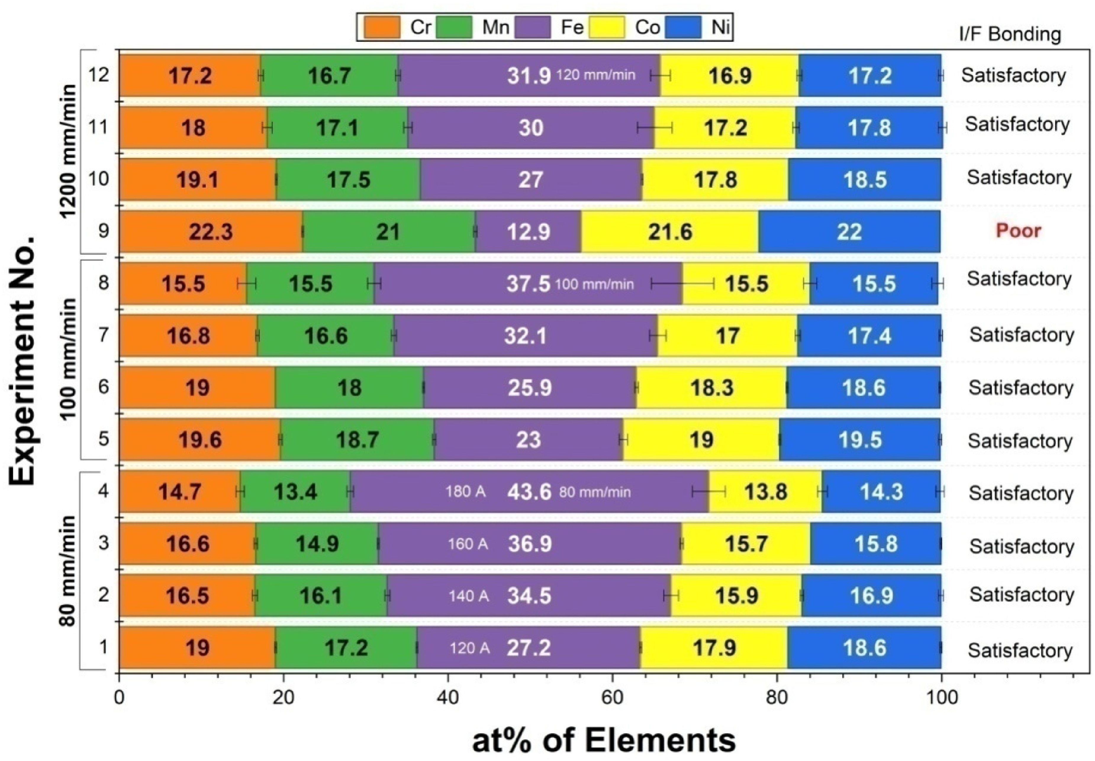
Compositional variation and interfacial bonding at the experimented range of cladding parameters (n = 10).
Wherein μ₀ denotes magnetic permeability (4π × 10−7 H/m), ‘I’ represents current, and r is arc radius. Elevating current from 120 to 180 A augments pressure by (180/120)2 = 2.25-fold, thereby intensifying substrate penetration and melt pool convection. Secondarily, elevated current raises plasma temperature, diminishing melt pool viscosity and promoting Fe diffusion from the substrate. 30 Tertiarily, current amplifies Marangoni convection induced by surface tension gradients, enhancing filler-substrate intermixing. 31 Quaternary, arc spreading expands with current, increasing substrate melting. 10 The observed dilution increment of 2.47-fold (12.9 to 31.9 at% Fe at 120 mm/min) correlates closely with the 2.25-fold pressure escalation, corroborating arc pressure as the predominant current-driven mechanism. Standard deviations were consistently below 1 at% across all conditions, signifying uniform in-situ alloying attributable to vigorous Marangoni (dγ/dT < 0) and Lorentz (J × B) convection within the GTAW molten pool, which homogenizes the multicomponent melt prior to solidification.25,32 It also should be noted that small EDS/WDS fluctuations only produce minor variations in Di and do not alter the overall identification of the dilution window or the optimized process condition as the Di is less sensitive to the compositional fluctuations.
Traverse speed exerts influence via residence time. Elevated speeds diminish heat input per unit length, thereby restricting Fe incorporation. At 160 A, decreasing speed from 120 to 80 mm/min elevated H.I. from 896 to 1344 J/mm, increasing Fe from 30 to 37 at%, in accordance with DuPont-Marder energy balance principles for single-pass arc welds. 11
Anomalies and non-monotonic behavior
Two deviations from monotonic trends were observed: (i) reduced dilution at higher heat input (120 A, 100 mm/min, 806 J/mm: 23 at% Fe vs 140 A, 120 mm/min, 784 J/mm, 27 at%); (ii) disparate dilutions at equivalent heat input (120 A, 80 mm/min versus 180 A, 120 mm/min, both 1008 J/mm, 27.2 versus 31.9 at% Fe). Heat input, being temporally averaged, neglects instantaneous arc dynamics. Dilution emerges from the interplay of arc pressure-dominated melting (scaling with I2, prevalent at high current) and conduction-limited melting (scaling with H.I., dominant at low current). At 120 A (∼14.4 kPa), subdued arc pressure constrains penetration irrespective of speed, at 180 A (∼32.4 kPa), pressure overrides residence time effects. This dual-mechanism paradigm extends conventional heat input frameworks, underscoring the necessity of current-resolved dilution evaluation for GTAW-based multi-principal element alloy in-situ processing.
Critical thresholds: critical heat input (H.I.c) and Critical dilution (Dc)
The parametric study shows a minimum substrate dilution that is necessary for reliable interfacial bonding, referred to as critical dilution (Dc), below which resulting a poor bonding. Understanding the dilution-bonding relationship is essential to define the critical heat input and dilution. An element-specific dilution index (Di) (Eq.4) was employed for better compositional predictability in MPEAs. 24 Di = 0 indicates no substrate contribution (composition = filler), Di = 1 indicates complete substrate replacement (composition = substrate), and Di > 0 represents concentrating and Di < 0 diluting elements. This formulation enables precise tracking of each element's dilution/concentration behavior.
Critical heat input (H.I.c) Identification
Plotting Di versus H.I. (Figure 4(a)) reveals distinct element specific dilution trajectories. At the lowest heat input (672 J/mm, Exp. 9), all elements cluster near the central reference line (Di ≈ 0), and indicating composition matches filler with negligible substrate melting. However, macroscopic observation (Figure 4(b)) and SEM interfacial analysis (Figure 4(d)) show semi-molten un-bonded deposits (balling), analogous to lack of fusion defects in laser powder bed fusion.
33
A sharp transition occurs at 784 J/mm (Exp.10). Fe dilution jumps from ∼12.9 to ∼27 at% (Di = 0 → 0.18), Co/Cr/Mn/Ni dilute proportionally, and bonding quality shifts from balling to sound metallurgical fusion (Figure 4(c) & (e)). This 672–784 J/mm interval represents the steepest dilution sensitivity region, analogous to balling-to-bonding transitions in arc-welding critical heat input studies.
24
The threshold H.I.
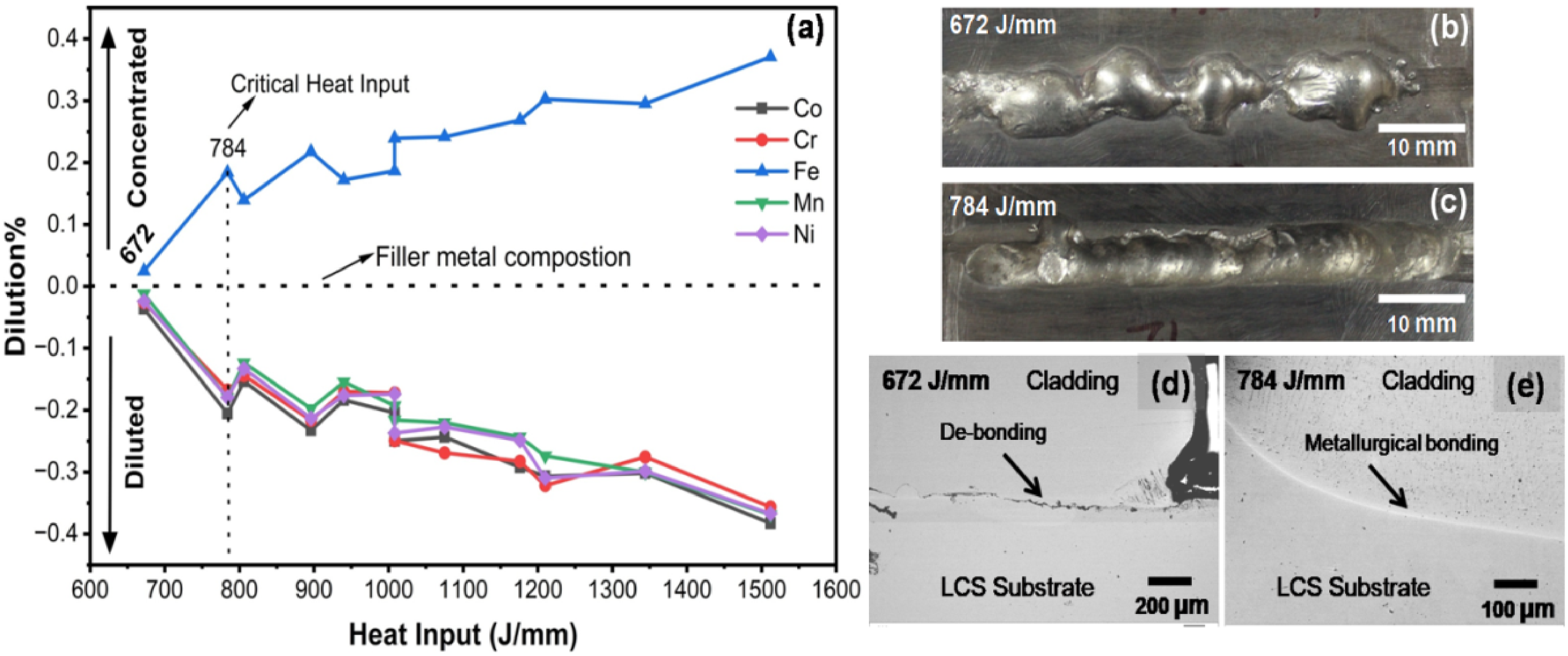
(a) Variation of the element specific dilution / concentration with heat input. (b & c) Macro images of the claddings at 672 and 784 J/mm respectively. (d & e) Cross sectional view at the interface of claddings at 672 and 784 J/mm respectively.
Critical dilution (Dc) as bonding threshold
The Fe dilution of 23 at% (Figure 3, Exp.5), representing a minimum substrate contribution for bond integrity. Below this threshold (Exp.9), insufficient substrate melting will prevents the mechanical interlocking and diffusion bonding. Above this threshold metallurgical bonding is maintained but composition deviates from equiatomic target (20 at% Fe), necessitating further refinement. Mechanistically, 23% Fe dilution ensures (1) adequate substrate penetration for interfacial Fe gradient establishment; (2) sufficient melt pool volume ratio (substrate:filler ≈ 1:3) to sustain convective mixing. 11 (3) thermal compatibility between substrate (Fe-dominant BCC) and filler (FCC-stabilizing Co/Cr/Ni) for epitaxial solidification at interface. These results explicitly confirm critical thresholds H.I. (∼784 J/mm) and least possible dilution without suffering the bonding exist as critical dilution (Dc) threshold for good bonding. The H.I and dilution thresholds were calibrated for single pass and 8 mm thick LCS substrate only. This will serve as a reference to multi-pass, multi-layer depositions and multi-thickness LCS substrate cladding studies.
Stage ii: compositional control via energy partitioning
Powder volume effect on dilution
In Stage II, the narrow process window from Stage I (120 A, 100 mm/min) was adopted as baseline, with powder volume fraction (Pv) varied from 20% to 60% in 10% increments. Compositions were analyzed and summarized in Figure 5, wherein the nominal equiatomic composition is depicted at the bottom (X-axis: element at%; Y-axis: Pv). Three claddings were deposited 
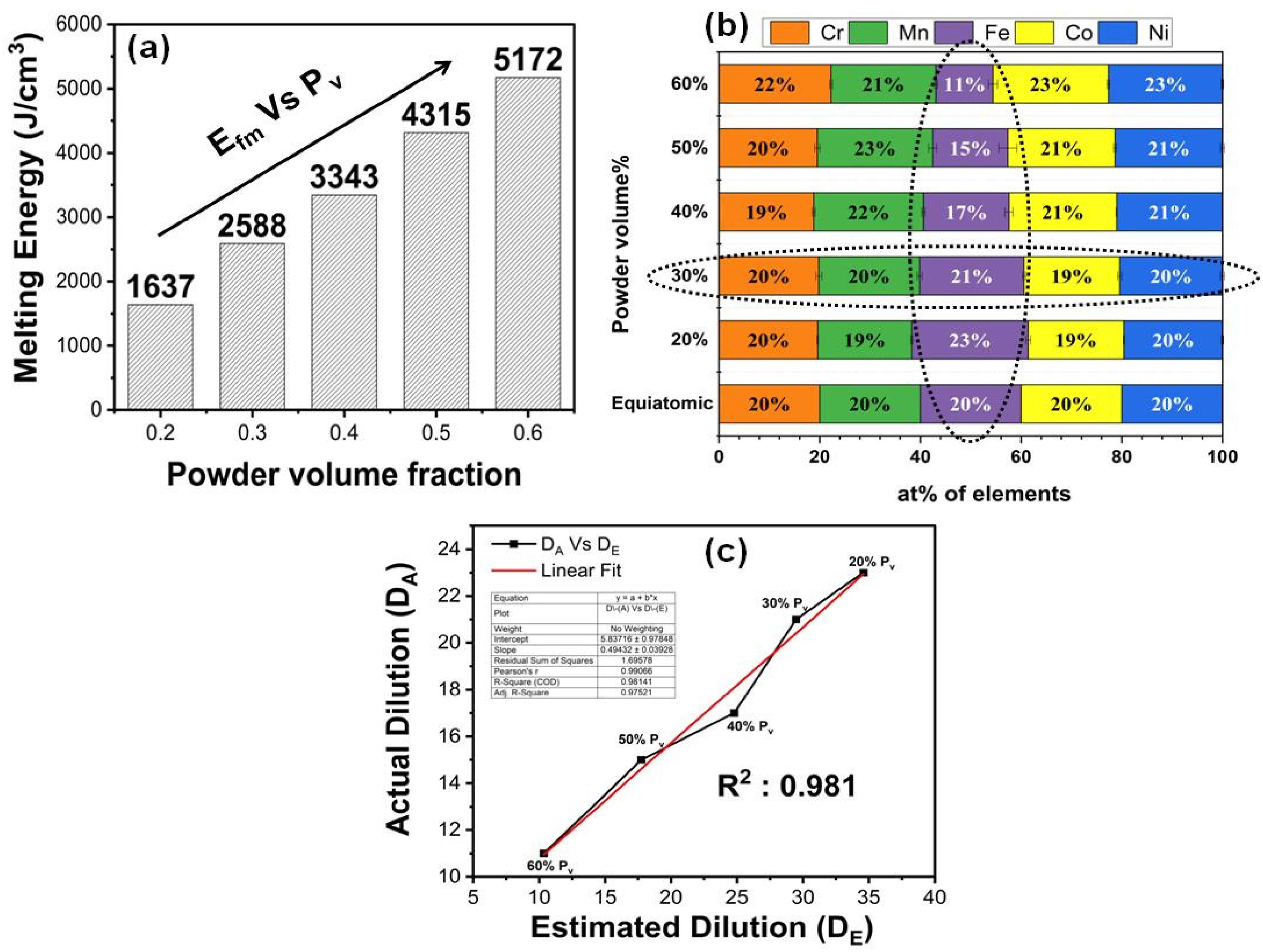
(a) Efm Vs Pv graph (b) Variation of CoCrFeMnNi MPEA cladding composition with respect to Pv (c) DE Vs DA graph.
Thermo-Calc based calculations (Figure 5) illustrate Pv's impact. Efm surges three orders of magnitude from 1637 to 5172 J/cm3 as Pv increases from 0.2 to 0.6 (Figure 5(a)), owing to greater solid mass and elevated heat capacity/latent heat of the Co–Cr–Mn–Ni mixture. Constant Earc thus curtails substrate volume melted, reducing Fe pickup. EDS data (Figure 5(b)) corroborate this fact and Fe falls from ∼23 at% (20% Pv) to ∼11 at% (60% Pv; vertical dotted circle), achieving equiatomic composition at 30% Pv (horizontal dotted circle). Co and Mn rise proportionally with declining Fe, whereas Ni and Cr remain stable, reflecting their higher diffusion activation energies (>300 kJ/mol vs. ∼270 kJ/mol for Co/Mn). 36 To verify dilution predictability over empiricism, estimated dilution (DE) from energy partitioning (modified Banovic model, accommodating no-feed filler and porosity for Pv dependent Efm) was compared to actual dilution (DA) from wide area EDS across Pv levels. Figure 5(c) reveals near-perfect correlation (R2 = 0.981), with 20–60% Pv data aligning tightly on the linear fit. This validates Fe dilution is possible to engineer via energy partitioning, predictable from thermo-physical data rather than trial-and-error. Thus, Stage II establishes Pv as a precise, quantitative lever for dilution control.
Structural characterization of the dilution engineered cladding
Figure 6 summarizes the solidification microstructure of the Pv optimized in-situ GTAW cladding. The macro and cross-sectional views (Figure 6(a)–(c)) show a sound single track bead with the classical sequence controlled by the temperature gradient (G) to growth rate (R) ratio G/R. 37 Near the fusion boundary, high G and low R (typically G > 105 K/m, R ∼10−2 m/s for arc welding) produce planar growth (Figure 6(d)), which evolves into columnar dendrites as G decreases and R increases with radial heat flow (Figure 6(e)). 37 When G/R falls below the critical threshold (∼2.5 × 10⁶ K·s/m2 for FCC alloys), a columnar to equiaxed transition occurs, giving fine equiaxed grains at the surface (Figure 6(f)).38,39 This G/R controlled progression agrees with reported CoCrFeMnNi GTAW welds and laser claddings, where columnar grains are typically 100–250 µm and equiaxed grains 20–80 µm.40,41 Grain size in the present cladding refines from ∼190 ± 50 µm (columnar) to 62.5 ± 19.6 µm (CET) and 30.6 ± 9.1 µm (equiaxed) at the surface (Figure 6(d)′–(f)′), matching ranges for arc welded Cantor alloys.42,43 This refinement reflects GTAW's intermediate cooling rates of 72–109 °C/s, higher than arc melting (∼10 °C/s, >500 µm grains) and lower than laser processing (103–105 °C/s). 44 These results show that dilution engineered GTAW can deliver grain refinement together with weld typical zoning, satisfying the microstructure equivalence component of the central hypothesis. 44 The reported G and R values are literature based contextual parameters used for interpretation, rather than directly measured quantities in the present work. The present study does not independently decouple dilution and cooling rate, because both evolve simultaneously during GTAW cladding. Dilution mainly controls the final chemistry through Fe pickup from the substrate, where as cooling rate governs the solidification morphology and grain refinement therefore, the observed microstructure is best interpreted as the coupled effect of composition and thermal history.
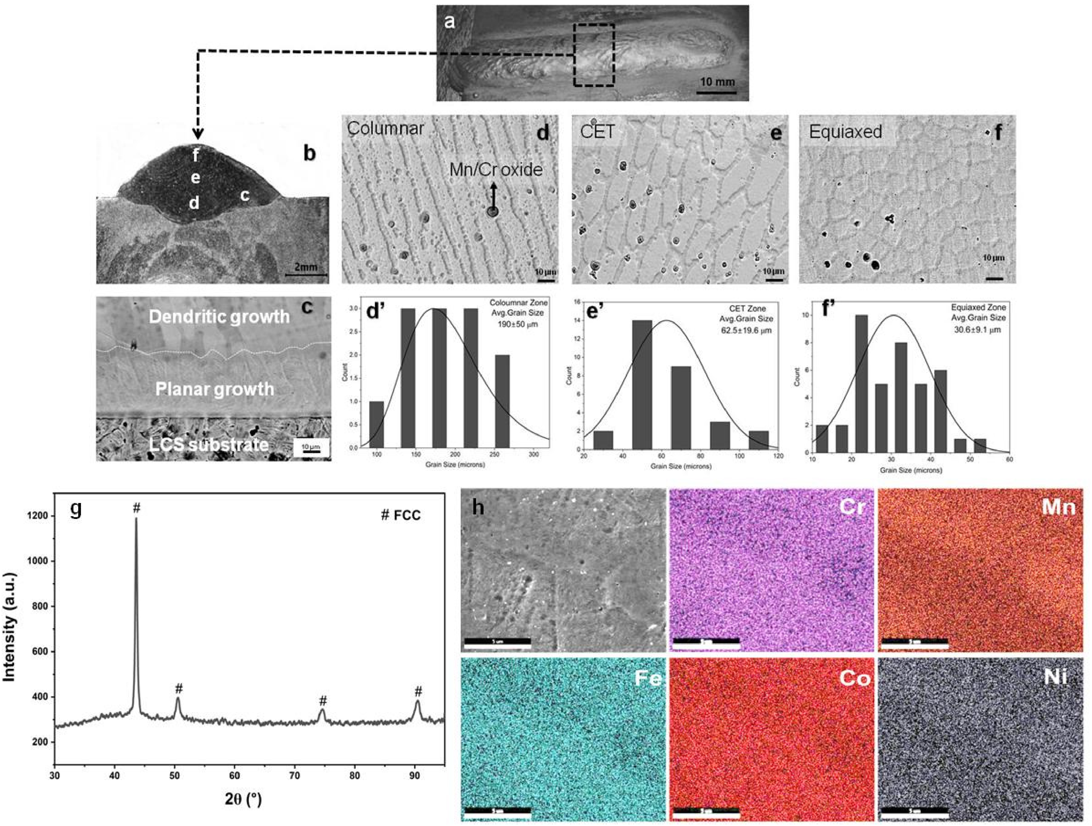
(a) Macro image of the Pv optimized cladding (b) Cross-sectional view (c) Microscopic image at the interface (d-e) Microscopic SEM images of different regions marked in image b (d’-f’) Grain size distribution at d,e and f locations (g) XRD phase analysis (h) Elemental mapping in the cladding.
XRD analysis (Figure 6g) reveals a dominant single FCC phase with peak positions corresponding to (111), (200), (220) and (311) and lattice parameter a ≈ 0.3594 ± 0.0003 nm (Nelson-Riley extrapolation) indistinguishable from equiatomic CoCrFeMnNi produced by vacuum melting or laser processing. This phase selection is fully consistent with established MPEA phase forming rules45,46 the CoCrFeMnNi in-situ cladding exhibits negative mixing enthalpy (ΔHmix = −4.5 kJ/mol), small atomic size mismatch (δ ≈ 1.6%) and valence electron concentration ≈ 8, all favoring FCC solid solution formation over intermetallics across the measured dilution range. The absence of secondary peaks above the XRD detection limit confirms that dilution engineering has retained the alloy within the FCC stability field. However minor phases below the detection limit of XRD cannot be completely excluded and EBSD or TEM would be required to detect nano-scale precipitates or ordering. High-magnification SEM–EDS elemental maps (Figure 6 h) reveal uniform distribution of Co, Cr, Fe, Mn, and Ni across the cladding, with minor micro segregation typical of as welded MPEAs and no macro-scale coring or banding. Sluggish diffusion in high-entropy liquids (η ∼10−3 Pa·s) 47 further suppresses coring during rapid 72–109 °C/s cooling, avoiding defects common in conventional alloys.
Micro-Hardness and bond strength assessment
The microhardness survey (Figure 7(a)) across the cladding substrate interface reveals a continuous hardness gradient without spikes indicative of no intermetallic formation, thereby validating the single-phase FCC integrity central to the dilution-engineering hypothesis. The LCS substrate exhibits a baseline hardness of ∼135 HV0.2. A sharp increase to ∼155 HV0.2 occurs within a ∼200 µm transition zone due to solid-solution strengthening from controlled Fe dilution (23 at%) and the onset of FCC lattice formation, which replaces the ferritic substrate matrix with the higher Peierls stress of the MPEA solid solution. 43 The vacuum-melted (VM) reference records 185–190 HV0.2, while the in-situ cladding surface achieves ∼210 HV0.2 an enhancement attributable to Hall-Petch strengthening from finer equiaxed grains (30.6 µm) developed under GTAW's elevated cooling rates (72–109 °C/s) relative to VM slow cooling (∼10 °C/s, coarse >500 µm grains).43,45 Interfacial bond strength, assessed by three-point bend testing (ASTM E 290) at optimized conditions (120 A, 100 mm/min, 30% Pv), has exceeded LCS yield strength. All specimens were bent >90° without any visible delamination (Figure 7(b); Figure S3). Superior bonding stems from (i) epitaxial nucleation across the coherent FCC–BCC interface facilitated by the shallow dilution profile, (ii) absence of thermal mismatch stresses due to matched CTE (∼17 × 10−6 K−1), and (iii) metallurgical intermixing without brittle phases.11,43 Post bend examination (Optical / SEM) has not been conducted to examine the presence of micro-fissures / cracks in the transition zone, which is crucial for the critical fatigue resistance applications, will be carried in the future studies.
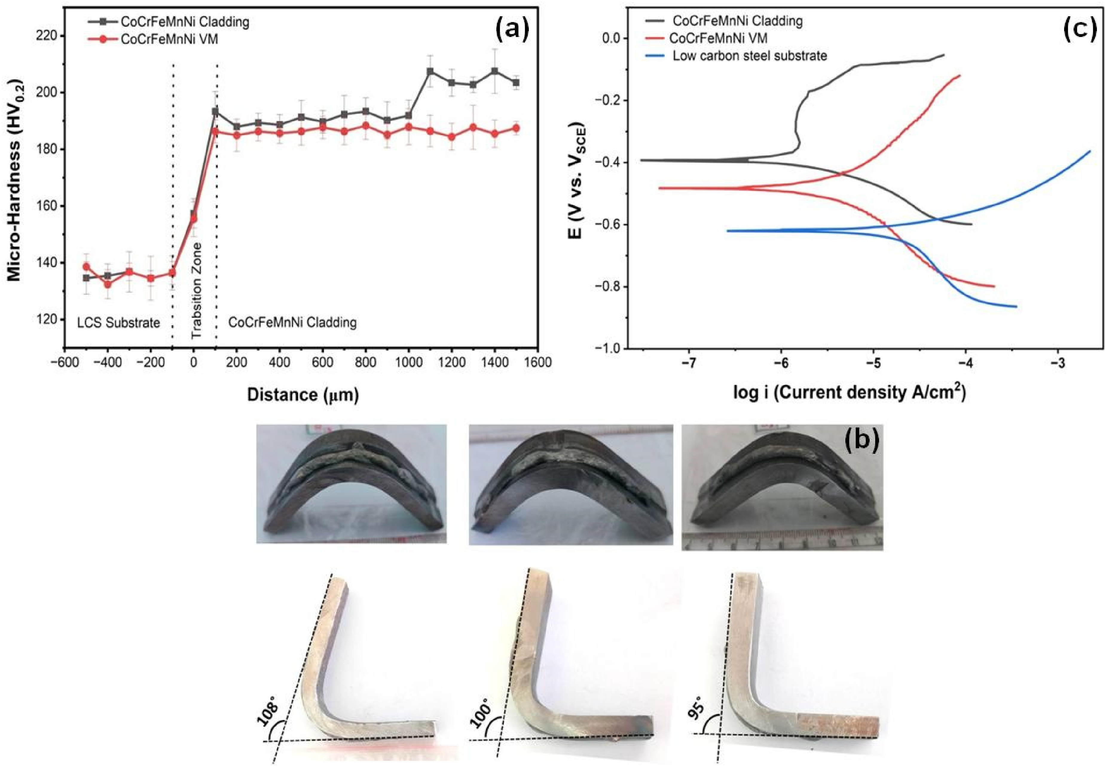
(a) Micro-hardness profile across the interface between LCS Substrate and cladding (b) Potentiodynamic polarization curves of the CoCrFeMnNi VM, Cladding and LCS substrate specimens in 3.5 M NaCl solution.
Corrosion resistance evaluation
Potentiodynamic polarization (PDP) curves (Figure 7(c)) for the in-situ CoCrFeMnNi cladding, VM alloy and LCS substrate show clear difference in the electrochemical parameters (TableS4, eq-5 & 6 supplementary data). 48 Both MPEAs exhibit passivation between −0.38 and −0.1 V (SCE). The in-situ cladding shows a stable passive region (−0.340 to −0.180 V), indicating a robust oxide film, whereas the VM alloy passivates less effectively due to its coarse microstructure. Grain boundaries will promote local galvanic activity, while very coarse grains reduce re-passivation pathways. Optimal corrosion resistance typically occurs at 10–70 µm grain sizes.49,50 The in-situ cladding's top surface grains (30.6 ± 9.1 µm) fall within this window, whereas the VM alloy (>500 µm) lies far outside, contributing to inferior performance. Cr/Mn oxide inclusions cover ∼1.5% area, Figure 6(d) and are isolated, not continuous. Though they are potential sites for localized attack, their limited extent and the stable passive behavior suggest minimal influence under the test conditions (3.5 wt% NaCl, RT, 30 min OCP). Grain refinement, rapid solidification, and minimized segregation enhance the cladding's corrosion resistance. Corrosion rates follow the trend of in-situ cladding (0.93 mpy) < VM alloy (2.17 mpy) << LCS substrate (44.77 mpy). The cladding also shows a nobler Ecorr (93 mV) and 57% lower Icorr than the VM alloy (217 mV). The results show an indication of promising short-term passive behavior, while long term immersion and localized corrosion testing are necessary for service relevant validation.
Conclusions
Equiatomic CoCrFeMnNi MPEA in-situ GTAW cladding was achieved via two-stage optimization using metal-cored fillers on low-carbon steel. Key outcomes encompass, an optimized window (120 A, 100 mm/min, 806 J/mm, 30% Pv) yielding ∼20 at% Fe dilution and robust bonding (>90° bend sans delamination). Critical thresholds (H.I.c ∼784 J/mm, Dc 23 at% Fe) demarcating balling-to-bonding transition, predictable dilution engineering, with modified Banovic predictions matching EDS (<1.5 at% deviation) for uniform equiatomic compositions. Pv control accessed low-Fe (11–21 at%) regimes unattainable by heat input alone, enabling scalable, crack-free MPEAs up to nine elements. Claddings exhibited FCC structure, dendritic morphology, and 185–210 HV0.2 hardness, rivaling vacuum-melted alloys. Superior corrosion resistance (Icorr) = 1.98 × 10⁻⁶ A/cm2 vs. 4.60 × 10⁻⁶ A/cm2) and surface hardness (210 HV0.2) arose from fine grains (30.6 ± 9.1 µm). This dilution-engineered GTAW approach, using commercial feedstocks, provides cost-effective, scalable coatings for power, marine, and chemical applications.
Supplemental Material
sj-docx-1-sen-10.1177_02670844261460164 - Supplemental material for Novel approach for dilution engineered CoCrFeMnNi in-situ weld overlay coating
Supplemental material, sj-docx-1-sen-10.1177_02670844261460164 for Novel approach for dilution engineered CoCrFeMnNi in-situ weld overlay coating by A. V. Sreenu, G. Phanikumar and B. S. Murty in Surface Engineering
Footnotes
Acknowledgements
The authors are gratefully acknowledging the support from RGUKT-A.P for the seed grant and infrastructure support to carry out the research. We also acknowledge DrT.Gopi and DrY.Palguna for participating in the technical discussions and providing valuable inputs.
Author contribution(s)
Funding
The authors received no financial support for the research, authorship, and/or publication of this article.
Declaration of conflicting interests
The authors declared no potential conflicts of interest with respect to the research, authorship, and/or publication of this article.
Supplemental material
Supplemental material for this article is available online.
References
Supplementary Material
Please find the following supplemental material available below.
For Open Access articles published under a Creative Commons License, all supplemental material carries the same license as the article it is associated with.
For non-Open Access articles published, all supplemental material carries a non-exclusive license, and permission requests for re-use of supplemental material or any part of supplemental material shall be sent directly to the copyright owner as specified in the copyright notice associated with the article.