
Abstract
Introducing coating layers on magnesium substrates for added corrosion protection has been one of the most popular methods to improve the relatively poor corrosion resistance of Mg biomaterials. Investigations on coating systems for Mg biomaterials to date have predominantly focused on smooth, polished surface topographies. Given that the corrosion resistance of biodegradable Mg increases with increasing surface roughness, the potential effectiveness of currently adopted coating methods could also be affected by changes in Mg surface topography. In this study, a biomimetic calcium phosphate (CaP) coating technique was employed to study the corrosion resistance of cast, pure Mg samples with high surface roughness of R a = 9·12 μm. The effectiveness of the coating technique on rough samples was tested in vitro and compared with that of the raw polished pure Mg samples. It was found that while the biomimetic coating technique provided excellent corrosion protection to the smooth polished samples, the improvement in corrosion behaviour of rough cast samples was not as significant. With the findings in this study, it is suggested that future studies on Mg coatings should be performed on rough as well as smooth surfaces for a complete evaluation on the effectiveness of the coating system.
Introduction
Magnesium (Mg) is the fourth most abundant cation in the body.1 Approximately 50-60% of physiological Mg is located in bone tissue, where it is one of the important constituents that make up the bulk of bone mineral.2 In addition to being an essential element for the human body, Mg is considered to be biocompatible and non-toxic and can be safely removed from the body via the kidney.2 – 4 Moreover, Mg and its alloys may offer advantages over current orthopaedic implant materials such as degradable polymers and bioceramics, or non-degradable cobalt-chrome, titanium or Ti alloys.5,6 These advantages include the more favourable mechanical properties, which are closer to that of native bone6 – 8 compared with non-degradable biometals, degradable ceramic hydroxyapatite and polymers, such as polycaprolactone and poly(ether–ether–ketone).9 Magnesium and its alloys offer a stiffness (E = 40-45 GPa) similar to cortical bone and appear to safely degrade in vivo.6,10 Despite the potential advantages, Mg has not yet been adopted clinically as bone interfacing medical device due to its excessive corrosion rate in the physiological environment due to the pH levels (7·4-7·6) and the high chloride conditions present in vivo.6,10 – 15 This leads to the risk that the implant may degrade too rapidly before the new host tissue can infiltrate and mature in order to support physiological loads in the affected site.
There has been significant interest in the development of surface coatings for Mg that is non-toxic and reduces the corrosion rate to acceptable levels for adoption in orthopaedic applications.6 Biomimetic precipitation of calcium phosphate (CaP) on the implant surface has been shown to be a simple yet effective coating method and attracted significant attention.16 Naturally, as various calcium phosphate phases are fairly insoluble in physiological conditions,16,17 they can be used to increase the material's corrosion resistance.18 – 20 CaP, being one of the main constituents in natural bone, has been used widely in coating strategies for orthopaedic implants, especially in Ti.16,17,21 – 24 Furthermore, CaP coatings can initiate a rapid biological response and therefore improve osteoconduction and integration between newly forming bone and the implant.16,17,21 – 23,25 Taking advantage of the properties of CaP and its popular usage in biomedical fields, many studies have applied biomimetic coating methods on Mg substrates and achieved positive results.19,26 – 29 For example, we have previously demonstrated that biomimetic CaP coatings improved the corrosion resistance of raw (i.e. as sourced non-cast) pure Mg.27 However, these studies were performed on samples with smooth surface finishes (1000-1200 grit)27,30,31 and do not necessarily reflect the range of surface topographies present on samples prepared by methods other than polishing or grinding, such as porous scaffolds or implants prepared via casting. For example, previous studies on topologically ordered Mg scaffolds manufactured using solid freeform fabrication and casting methods introduced a surface roughness of up to 11·15 μm.32 As far as the authors are aware, few studies have investigated the performance of coating techniques on Mg substrates with rough surface topographies.
Furthermore, the corrosion behaviour of degradable biometals may be adversely influenced by the topologically rough surfaces. For example, an in vivo study on Mg0·8Ca showed that the structural loss of smooth machined samples was less than that of the sand blasted samples.33 In a more recent study, we investigated the influence of surface roughness on the in vitro corrosion behaviour of pure Mg samples with a wide range of roughness values (R a = 0·59-9·12 μm) and reported an accelerated corrosion rate with increasing surface roughness.34 In addition, Walter and Kannan confirmed that the increasing surface roughness showed an adverse effect on the pitting potential of AZ91D.35 Given that the samples with rough surface texture are more susceptible to corrosion, the coating media potentially introduce corrosion to the sample during the coating process. Moreover, due to the different surface topologies, the adhesion of the coating layer formed on the rough surfaces may be different from that on the smooth surfaces. Therefore, it is likely that Mg samples with different surface topologies will behave in a significantly different manner during the coating process.
In this study, the widely adopted biomimetic CaP coating technique was employed to increase the corrosion resistance of cast pure Mg substrates with rough topographies (R a = 9·12 μm). The in vitro corrosion behaviours of CaP coated and uncoated rough Mg samples were assessed via a range of corrosion testing techniques, including hydrogen evolution, electrochemical impedance spectroscopy (EIS) and potentiodynamic polarisation (PDP). The findings were compared with the corrosion properties of the as sourced polished Mg samples to evaluate the performance of the coating technique on the rough Mg substrates.
Materials and methods
Material
Commercially pure Mg 99·98% (Timminco Ltd, Canada) was utilised for this study in order to limit any influence of impurities on the corrosion behaviour. Impurities as detected by inductively coupled plasma atomic emission spectrophotometry (Spectrometer Services, Coburg, Victoria, Australia) were <0·002 wt-%Ca, <0·005 wt-%Al, <0·005 wt-%Zn, <0·002 wt-%Zr, <0·001 wt-%Fe and <0·002 wt-%Cu. Mg samples with rough surface finish were manufactured using a previously described indirect solid freeform fabrication and casting route.32,36 Briefly, the main steps of the manufacturing process were: (i) using computer aided design to create a three-dimensional model with the desired architecture; (ii) rapid prototyping printing of a positive polymeric template of the computer aided design model; (iii) infiltration of the polymeric template with a NaCl paste; (iv) burn out of polymeric materials and sintering of NaCl; and (v) infiltration of the negative NaCl template with liquid Mg and removal of the NaCl template. Results from inductively coupled plasma atomic emission spectroscopy and energy dispersive X-ray spectroscopy indicated negligible concentrations of residual NaCl (<0·03 wt-%) were present on the final samples.
In this study, the cylindrical rapid prototyping mould design consisted of 0·5 mm thick vertical plates separated by thick channels, as described previously.34 This process resulted in a NaCl template that introduced a surface roughness of R a = 9·12±0·44 μm to the cast Mg product. Each plate in the final Mg part was cut into 10×10×4 mm square block using a TechCut 5 precision sectioning machine (Allied High Tech Products Inc., USA) and diamond blade (thickness of 0·02 in) at low speed of 1800 rev min−1 and low feedrate of 1·25 mm min−1. The surface roughness (R a) of all the samples was measured using a surface profilometer (Dektak 150, Veeco). A similar cutting process was employed to prepare smooth polished samples. Pure as sourced Mg material was cut into 10×10×4 mm square block and polished to 1000 grit using SiC paper. All samples were rinsed in ethanol for 10 min, air dried and stored in desiccator before coating.
Biomimetic calcium phosphate coating
The biomimetic CaP coating process was performed as described previously by Waterman et al.27 The coating process involved two separate stages in which different modified simulated body fluids designed with reduced chloride ion (Cl−) concentration were prepared with chemical composition, as described previously.27 Solution 1 had a higher concentration of carbonate ions ( ) to promote the formation of amorphous CaP, while solution 2 was designed to have a low Mg2+ ion concentration to promote crystalline apatite formation.17,37 Each solution was heated to 37°C before carbon dioxide gas [CO2(g)] was bubbled through to reduce the pH to 6 for the solution. When the desired pH was reached, CO2(g) was removed from the solution, and air was bubbled through. In the first stage, Mg samples were immersed in solution 1 for 24 h. During this process, a magnetic stirrer was employed to mix the solution and consequently generate a uniform ionic concentration. After 24 h, the samples were removed and rinsed in distilled water before being put into solution 2 for another 24 h. The pH of solution 2 was also controlled by the same application of CO2 and air.27
To study the morphology of the coating layer, coated samples were analysed under scanning electron microscopy (SEM; JEOL 7000F FE-SEM). One smooth coated sample analysed by X-ray diffraction spectroscopy (PANalytical X'Pert-Pro MPD PW3040/60) was used to determine the surface chemical composition.
Corrosion testing methods
The in vitro corrosion behaviour was evaluated using a range of techniques, including hydrogen evolution, EIS and PDP. To mimic the in vivo human body environment, Hank's balanced salt solution (HBSS, H6136, Sigma-Aldrich NZ Ltd), which contained ions commonly found in the human blood, such as Ca2+ and  , was used in all in vitro corrosion experiments. The HBSS was buffered with 5·96 g L−1 of 2-[4-(2-hydroxyethyl)-1-piperazinyl] ethanesulfonic acid (H3375, Sigma-Aldrich NZ Ltd). Temperature was maintained at 37±0·5°C, and the pH was buffered at 7·4±0·05 throughout the experiments with aid from a SevenEasy S20 pH/Temperature meter and LabX pH meter (Mettler-Toledo Inc., Columbus, OH, USA).
Hydrogen evolution analysis of Mg corrosion has been widely reported and has become a reliable method in Mg corrosion testing.38 – 41 In this study, hydrogen evolution testing was performed as described previously.34,41 The tests were performed on samples (n = 4) with 1 cm2 of coated or uncoated surface exposed to 400 mL of HBSS. Marine grade silicone (Selleys, Australia) was used to prevent corrosion on other surfaces of the sample. The testing solution was maintained at 37°C via a heated water bath. H2(g) generated by the corrosion reaction was collected using a funnel (Ø = 5 cm) placed directly on top of the sample, with H2(g) accumulated in a 50 mL burette placed vertically over the funnel. At the beginning of the experiment, the burette was filled with testing solution. Since the evolved H2(g) displaces the solution inside the burette, this provides a direct correlation with the volume of H2(g) produced. The liquid level was recorded every 30 min with a precision of ±0·1 mL. The solution was also manually stirred at each reading to reduce the likelihood of a localised increase in pH at the sample surface.
The EIS and PDP experiments were performed on a BioLogic SP-150 potentiostat, controlled by EC-Lab 10·02 software (BioLogic Inc., Knoxville, TN, USA). In both tests, a three-electrode flat cell (K0235, Princeton Applied Research, Oak Ridge, TN, USA) containing 300 mL HBSS was used. The sample had an exposed surface area of 1 cm2. The working voltage ranged from −3 to 0 V for EIS tests to cover the full range of potentials encountered while maximising the resolution of the tests (50 μV). A frequency range of 10 kHz to 30 mHz was used for the EIS scans. The first two scans were performed after the samples were exposed to HBSS for 15 and 30 min. The 15 min time point was chosen since it was sufficient time for the surface to stabilise the solution. Subsequent scans were carried out after every 30 min. The Nyquist plots achieved from EIS experiments were analysed by fitting to the equivalent circuit model consisting of a parallel resistor and capacitor in series with a resistor. A scan rate of 1 mV s−1 was used for PDP, and each test was carried out in the range of −150 mV below the open circuit potential to 500 mV above. Similar to EIS, the first PDP scan was performed after the sample was immersed in HBSS for 15 min, and subsequent scans were at 30 min intervals. Tafel type analysis was performed at points ±50 mV outside of the corrosion potential. After corrosion testing, the surface morphology and composition of pure Mg samples were analysed using SEM and energy dispersive X-ray spectroscopy respectively.
Since the total surface area and roughness of the test region increased as corrosion proceeded, the testing period was limited to 6 h for uncoated samples to provide adequate data while minimising the change in surface area during the test. Meanwhile, the test period was increased to 24 h for the rough coated samples, smooth coated and uncoated samples since with the extra corrosion protection from the coating layer the sample was expected to withstand a longer corrosion testing period.
Results and discussion
Coating formation and surface examination
The surface roughness (R a) values of the rough cast and raw smooth samples, as determined by surface profilometry, were 9·12±0·44 and 0·59±0·04 μm respectively. The surface of the rough Mg substrate was of uniform topology with distinctly different surface roughness (Fig. 1a and b). The surface morphology of the coating on the rough samples was examined and compared with that on the smooth sample (Fig. 1). At macroscopic level, the coating layer on the polished Mg sample appeared to be consistent and smooth (Fig. 1g). Meanwhile, varying surface morphologies were observed on the rough coated samples with thick CaP flakes in some regions and thin layers elsewhere (Fig. 1d). At the microscopic level, cracks and defects (as shown by the arrows) were observed in both rough and smooth coated samples (Fig. 1e and h).27 Following corrosion tests, these cracks and defects became more apparent (Fig. 1f and i).
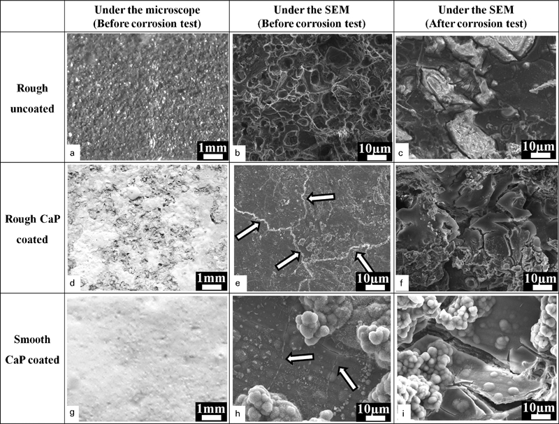
Surfaces of a–c rough uncoated, d–i rough coated and g–i smooth coated samples under light microscopy and SEM before and after corrosion testing: arrows indicate cracks and defects in coating layer
X-ray diffraction analysis of the polished coated samples demonstrated that the crystal structure of the coatings was most similar to dicalcium phosphate dihydrate or brushite (Fig. 2). The coatings were not completely crystalline, as evident from the broad peaks.

X-ray diffraction profile of smooth coated sample
The corrosion of substrates during the biomimetic coating process was problematic on rough cast samples and caused significant damage to a number of these substrates, which were identified as failed coatings. The success rate in coating rough as cast pure Mg samples was 80%, whereas it was 100% for smooth polished Mg substrates.
Hydrogen evolution
Hydrogen evolution data showed a reduction in the volume of H2(g) evolved from the coated compared with the uncoated samples, irrespective of their surface finish (Fig. 3). The rough uncoated samples rapidly corroded, producing an average of 48·87±0·5 mL cm−2 of H2(g) after 6 h, which was equivalent to ∼195·48 mL/cm2/day. The biomimetic CaP coating decreased that figure down by >×7 to 25·63±4 mL/cm2/day. Meanwhile, for the smooth polished samples, the coating technique reduced the H2(g) volume by nearly ×4, i.e. from 1·54±0·2 mL/cm2/day for the smooth uncoated samples to 0·41±0·3 mL/cm2/day for the smooth coated versions. Without the coating layer, the rough sample evolved ×130 the volume of H2(g) as the smooth polished Mg. With the CaP coating layer, this difference was reduced by half, while the corrosion rate of the rough coated sample was ˜×63 higher than that of the smooth polished version.
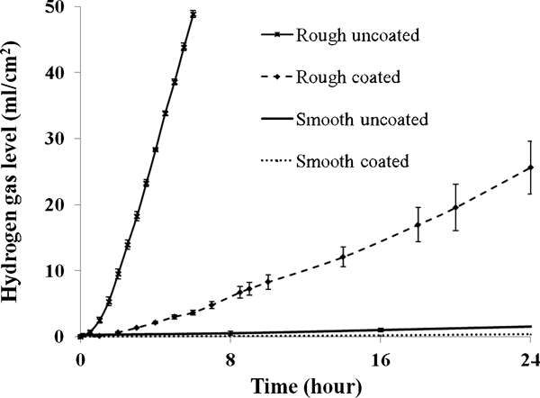
Hydrogen gas evolution for all samples
Impedance tests
In the first hour, the rough coated samples showed a slightly higher corrosion resistance than the uncoated rough version (Fig. 4a). However, the difference became insignificant after 1 h, with corrosion resistance at 6 h time point of 40·94 and 33·05 Ω for the rough CaP coated and rough uncoated samples respectively. Both uncoated and coated rough samples shared a similar trend in changing the corrosion resistance values over time. The initial corrosion resistance was high at the start of the test but decreased after 2 h and maintained at this level for the remainder of the test. This trend of changing corrosion resistance was relatively different from that of the polished samples. While a steady increase was observed on the polished uncoated sample over 24 h testing, there was a quick drop in the first 6 h for the smooth coated sample, followed by a stable increase (Fig. 4b). At the start of the corrosion test, the rough coated samples showed a similar corrosion resistance to the smooth uncoated sample. However, after 24 h, the corrosion resistance of the rough coated samples was ×32 and ×70 lower than that of the smooth uncoated and coated samples respectively. In contrast with the rough sample, in which the coating technique slightly improved its corrosion resistance, the smooth polished sample showed a significant increase in corrosion resistance before and after the coating process. The second time constant, which represents the resistance of the coating layer, was not observed for the coated rough samples (Fig. 4c) but was shown in the smooth polished versions (Fig. 4d).
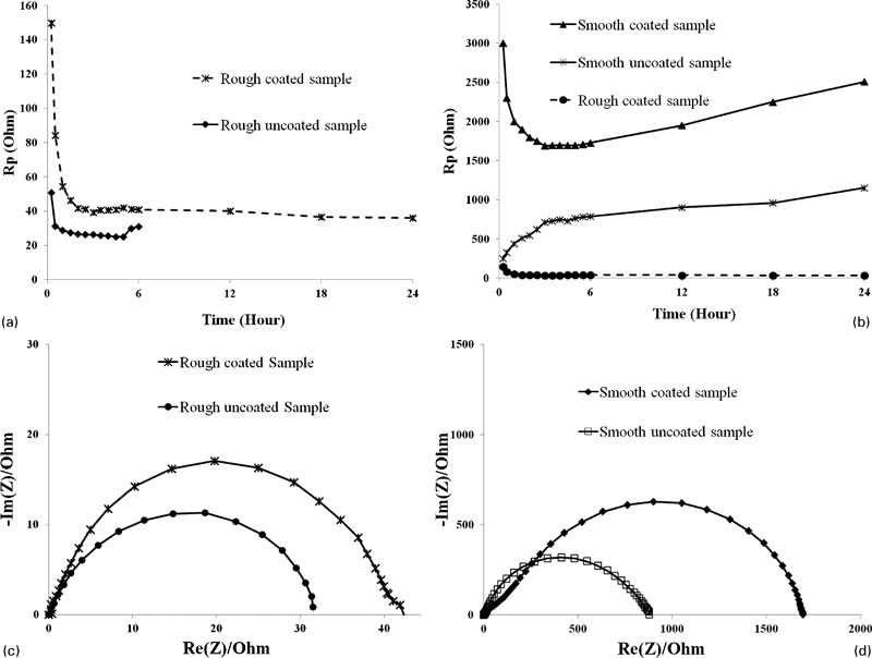
Change in corrosion resistance a over 6 h for rough uncoated and over 24 h for rough coated samples, b over 24 h for rough coated, smooth coated and uncoated samples, and Nyquist plots of corrosion resistance at 6 h for c rough cast samples and d smooth polished samples adapted (note difference in resistance magnitude between smooth and rough samples)
Polarisation behaviour
Both uncoated and coated rough samples showed a trend of increasing corrosion current density (i corr value) over time. The rough uncoated samples showed a significant increase in i corr value within the first 2 h, i.e. from 368·4 to 511·9 μA cm−2, and then subsequently increased at a slightly slower rate. Similarly, the resulting i corr value measured on the rough coated sample was 256 μA cm−2 initially and then gradually increased to 343 μA cm−2 after 6 h, which was approximately half that of the rough uncoated samples. The current density of the coated rough samples remained relatively constant beyond 6 h. From the polarisation curves, the smooth coated sample showed the lowest i corr value, which was followed by the smooth uncoated samples, rough coated samples and finally the rough uncoated samples (Fig. 5). While both rough samples, coated and uncoated, showed dominant behaviour of anodic polarisation, both smooth samples presented a shift in the cathodic branches of the polarisation curves.
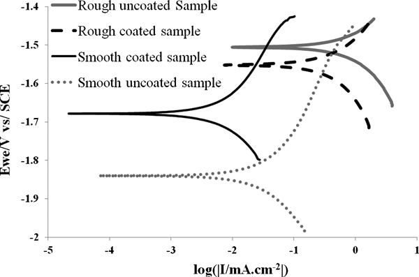
Tafel plots of all samples at 6 h time point
Discussion
As previously reported, the corrosion of the Mg substrate during the biomimetic coating process assists the deposition of the coating on smooth polished samples.42 However, given the low success rate in coating rough Mg samples, this phenomenon appeared to be detrimental to rough cast samples, which was reported to have low corrosion resistance compared with the smooth substrate.33,35 Although this study used a low Cl− ion concentration in the biomimetic coating media, immersing rough Mg substrates that were highly susceptible to corrosion for a total of 48 h still introduced significant corrosion to the samples.
The biomimetic coating process creates brushite coatings (Fig. 2). Coatings of this type are not completely crystalline, which is important to the stability of the coatings.16 This effect was likely due to substitutions by magnesium and carbonate ions during the biomimetic coating process,25 which affect the growth of the CaP crystal structure and decrease the overall crystallinity.43,44
On the rough Mg substrates, cracks and defects in the CaP coating layer could be observed in the macroscopic level and suggested an inconsistent and unstable coating layer. The defects potentially allowed continuing corrosion to occur and was likely the primary failure mechanism of the coating.27 This was demonstrated by the linear increase in H2(g) evolution over time. Owing to the rapid change in the surface conditions after corrosion of CaP coated samples, it was suspected that continuing the test for over 24 h, the surface area and roughness of the sample would also change significantly to produce meaningful data. Hence, the test was stopped at 24 h.
Results from hydrogen evolution tests suggested that the biomimetic CaP coating layer provided only limited corrosion protection, corresponding to a slight reduction in the corrosion rate of Mg with rough surface topography. However, the rate of evolved H2(g) in the rough coated sample was still considerably high in comparison with that of both smooth uncoated and coated samples. Considering the theoretical H2 gas absorption limit in human body of 2·25 mL/cm2/day,45 while both smooth samples were within the limit, the rough version with coating layer still produced a volume of H2(g) that was ×11 higher than the suggested limit, and this potentially leads to accumulation of H2(g) in vivo. Therefore, the improvement in corrosion protection introduced by the CaP coating on Mg samples with rough surface finish could be considered insufficient for applications such as load bearing orthopaedic devices where mechanical properties and slower degradation rates/H2(g) accumulation is preferable.
Results from EIS tests supported the observation in the hydrogen evolution tests, with the biomimetic coating increasing the corrosion resistance of both polished and rough cast samples. As explained previously, the corrosion occurring beneath the coating as a result of cracks may undercut the coating layer and decrease its adhesion to the sample. In other words, the Mg substrate in some regions may be left exposed to the solution due to the failure of the coating layer.27 Given the coating topologies on the rough samples displaying more defects than the smooth coated samples, the integrity of the coating on the rough substrate was considerable poorer. As a result, compared with the considerable increase in corrosion resistance of smooth samples before and after coating, the insignificant improvement in resistance of the rough coated sample indicated that the coating was much less protective on the rough substrate. As reported in previous studies, additional precipitation of CaP on the surface may result due to the existing elements in the HBSS and local pH rise, especially at defects in the coating layer where corrosion proceeded.5,27,46 However, since the corrosion resistance of the CaP coated sample was observed to decrease and remained unchanged over time, this repassivation phenomenon did not appear to occur or did not occur rapidly enough on Mg samples coated with CaP techniques in this study. The lack of obvious secondary time constants that represent the impedance due to the coating in the rough coated samples provides evidence that biomimetic coatings did not possess sufficient integrity to significantly slow corrosion rates.
The PDP test results further confirmed the findings in both hydrogen evolution and EIS experiments. With lower i corr values, the rough coated samples were less vulnerable to corrosion than the uncoated version. However, with the current density values remaining relatively the same after 24 h testing, the formation of any repassivation layer was confirmed to be not effective enough to improve the corrosion properties of rough Mg samples over time. Moreover, the Tafel plot (Fig. 5) of the rough samples with strong anodic shift indicated that the CaP coating layer did not sufficiently improve the corrosion protection of Mg with rough topologies. The Tafel plot of the smooth coated sample showed a large decrease in anodic reaction rate due to the applied coating, which helped lower the current density.
Considering the disadvantageous corrosion properties of Mg substrates with rough surface texture on the coating performance, results from this study suggest that techniques to further reduce the surface roughness of Mg samples will be beneficial. This can be achieved via modifying the related casting parameters, to employ Mg alloys instead of pure Mg or decrease the roughness of the NaCl template that the molten Mg conforms to. Viscosity of a material is one of the main factors that influence the ability of a molten metal to flow through and to fill a mould cavity before solidification occurs,47 and it is known that the viscosity of pure metal is often better than that of its alloys.48,49 Therefore, is it likely that casting porous Mg implants using Mg alloys will likely result in an implant surface that is significantly less rough than with pure Mg. For example, using the current casting technique, we observed a ×5 reduction in R a on cast AZ91 substrates compared with pure Mg (unpublished data). Furthermore, due to the observed poor adhesion and inconsistency of the coating layer in this study, especially on rough samples, there is a need for the further development of alternatives to biomimetic coating methods that can provide continuous corrosion protection to smooth and rough Mg substrates.
Conclusions
In general, the biomimetic CaP coating method was shown to provide limited corrosion protection for the as cast pure Mg samples with rough surface topographies (R a = 9·12 μm). However, the level of protection observed on the rough samples was significantly lower compared with that on smooth, polished pure Mg. For the rough Mg substrate, there was a slight change in volume of evolved H2(g), corrosion resistance and current density before and after applying the coating. Moreover, the biomimetic CaP coating was shown to be a less suitable method for Mg samples with rough surface finish due to the fact that corrosion occurred on samples during the actual coating process. More importantly, the resulting coating layer was inconsistent, with cracks and defects observed on the surface, allowing corrosion to occur at these sites. Therefore, while the biomimetic coating technique was shown to provide effective corrosion protection on the smooth polished samples, it may not be suitable for rough cast samples.
To improve the corrosion resistance of the as cast Mg samples, which inherently exhibit rougher surface topographies than commonly adopted Mg implants with machined or polished surfaces, future work should evaluate coatings on cast Mg alloys as well as raw material to further assess their ability to enhance corrosion resistance.