
Abstract
The iron and steel industry is one of the main sources of global carbon emissions, and the development of new technologies for CO2 resource utilisation is crucial for achieving the ‘double carbon’ goal. In this article, the decarbonisation of CO2 in steel refining and its thermodynamic mechanism is investigated, and the effects of initial carbon content, smelting temperature and CO2 blowing flow rate on the decarbonisation effect are analysed by combining with Factsage calculations and high-temperature experiments. The reaction involved in the CO2 can mildly control the molten pool temperature, and decarbonisation is a three-phase coupled process of gas-slag-metal with the elemental mass transfer of carbon as a rate-controlling link. It was found that the decarburisation rate was accelerated with the increase of carbon content when the initial carbon content was more than 0.11%; the larger the CO2 blowing flow rate, the faster the decarburisation rate; the temperature has less influence on decarburisation, but the temperature rise in low carbon steel liquid can improve the decarburisation rate. CO2 can be used as an effective decarburising agent, and optimisation of the parameters can increase the decarburisation efficiency, and help reduce the emission of the iron and steel industry.
Introduction
The CO2 emissions from the steel industry account for 7% of the total global carbon emissions, and the steel industry, as a pillar industry, radiates all walks of life and the demand is increasing year by year, so it is imperative to reduce CO2 emissions and develop new technologies to utilise CO2 resources.1–3 In recent decades, the application of CO2 in the steelmaking process has been widely explored, mainly focusing on its role as an oxidising agent, protective gas or stirring medium.4–6 Early studies by Lu et al. 7 showed that the injection of CO2 from the top and bottom in a 30t converter could reduce furnace dust and improve the dephosphorisation efficiency. Subsequently, Yu et al. 8 further improved the bath agitation and dephosphorisation rate by optimising the CO2 injection time. These studies emphasised the potential of CO2 in reducing iron losses and improving the slag–metal equilibrium. Chen et al. 9 experimentally verified that CO2 can replace argon as a protective gas and achieve comparable inclusion removal efficiency while reducing costs. Similarly, Anderson et al. 10 utilised CO2 as a shielding gas in an electric arc furnace and significantly reduced nitrogen uptake in molten steel. These findings emphasise the dual function of CO2 in protection and environmental control. Han et al.11–14 pioneered the use of CO2 as a lifting gas in vacuum refining and demonstrated its ability to reduce equilibrium carbon content under vacuum conditions. Their study showed that the injection of CO2 altered the selective oxidation behaviour of carbon and aluminium, providing a new avenue for the production of low-carbon steel. Despite these advances, two key gaps remain: most studies have focused on macroscopic process optimisation (e.g. dust reduction, enhanced stirring), but mechanistic studies of the thermodynamic interactions between CO2 and steel are lacking. The equilibrium conditions and rate-limiting steps of CO2-driven decarbonisation reactions at refining temperatures (1500–1700°C) are still not fully quantified.
In order to fill these gaps, this study systematically investigates the thermodynamic mechanism of CO2 participation in the decarbonisation of Fe–C alloys by means of thermodynamic calculations (Factsage) and experimental methods. By analysing the effects of initial carbon content, temperature and gas flow rate, we aim to lay a theoretical foundation for the industrial utilisation of CO2 in low-carbon steelmaking.
Research methodology
Thermal state experiments
Test materials
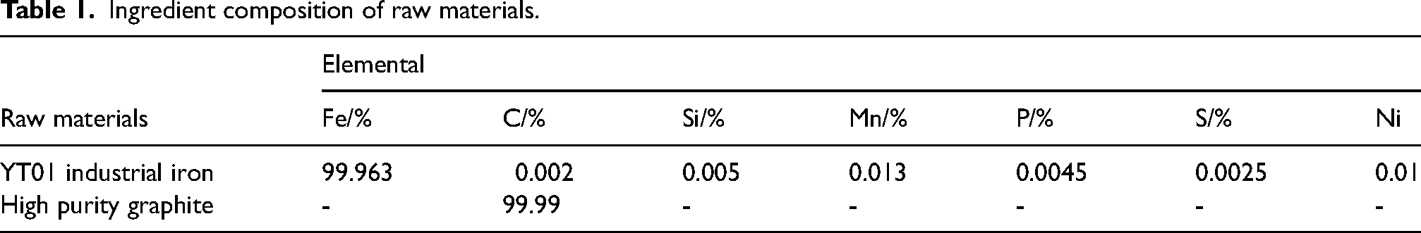
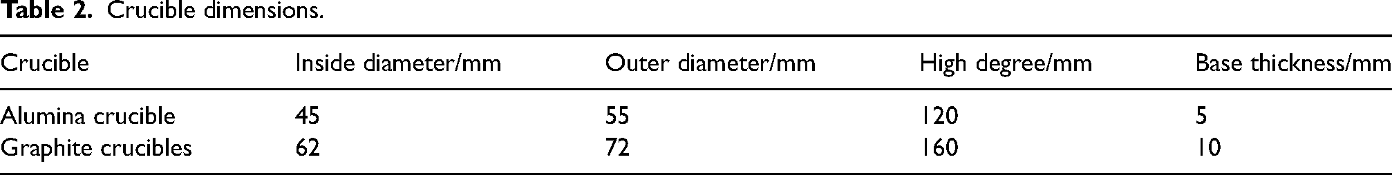
Experiments were conducted to prepare Fe–C alloy using YT01 industrial pure iron and high-purity graphite powder. The compositions of the alloys are shown in Table 1. An alumina crucible was used as the reaction vessel in the experiment, and measures were taken to prevent the spattering of iron liquid during the reaction. The specific operation was to place the configured alloy material inside the alumina crucible and then wrap the graphite crucible on the outside to further prevent the liquid iron from spattering and protect the furnace body. The schematic diagram and dimensions are shown in Figure 1 and Table 2, respectively.
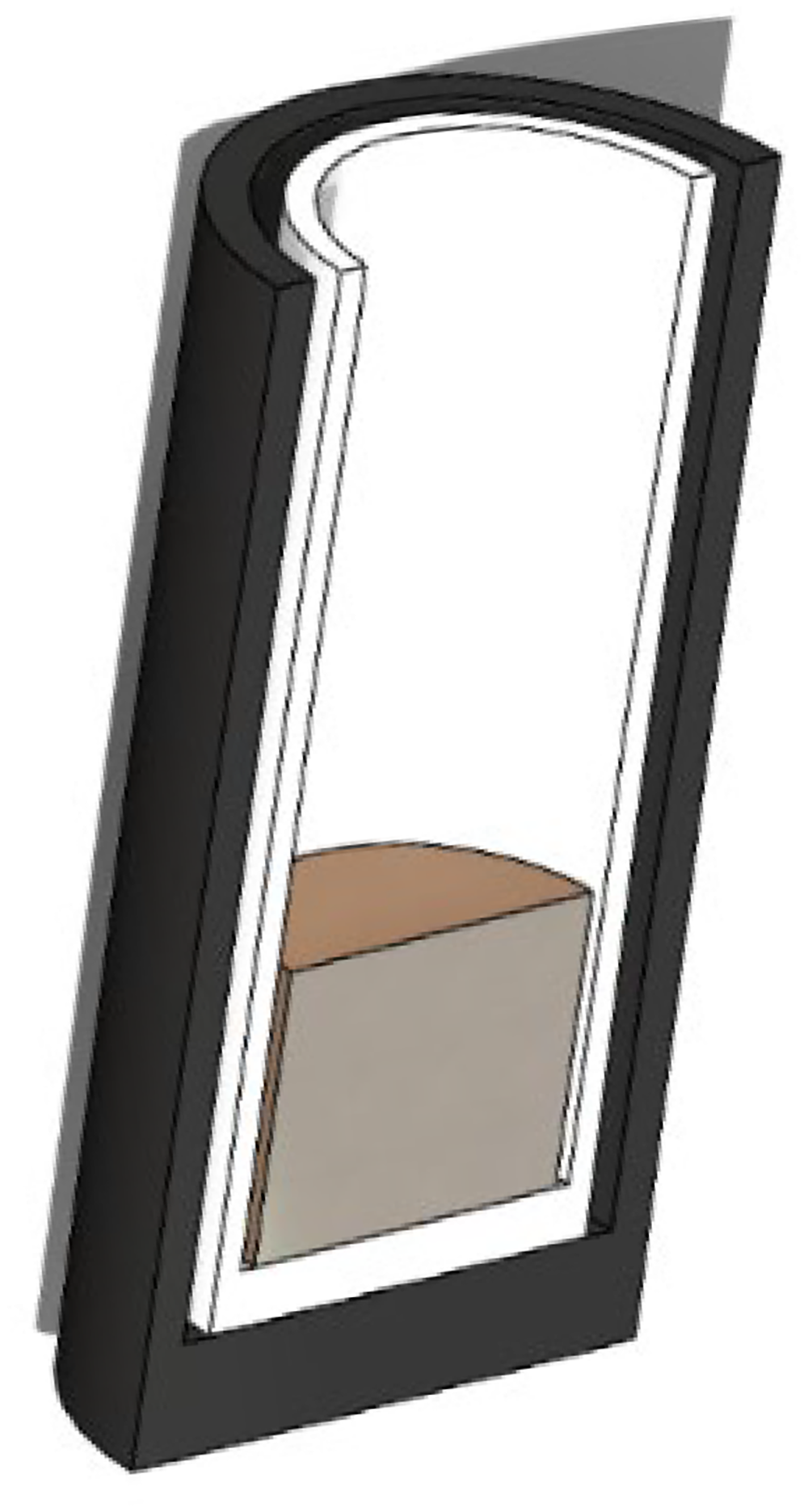
Schematic diagram of loading.
Ingredient composition of raw materials.
Crucible dimensions.
The heating size of the tube furnace used in the experiment is 90–400 mm, and the constant temperature zone is 200 mm. In order to ensure the experimental effect, the amount of experimental ingredients is generally loaded in 1/3 of the crucible height, and the ingredients used in the experiment are about 300 g. The calculation of the ingredients is as follows.
A total of 300 g of experimental melt of Fe–C system can be calculated from the following formula by dividing the total mass, i.e. elemental carbon content, by the carbon content in pure iron plus the carbon content in graphite powder:

Eq:
Research equipment
The furnace is equipped with a 50-segment programmable temperature control system, capable of ±1°C temperature control above 300°C, and is designed for heating materials under vacuum and specific atmospheric conditions (e.g. inert gas, argon, etc.). The 3D model of the equipment is shown in Figure 2. The protective gas used in the experiment is high-purity argon, which is injected from the bottom of the furnace to isolate the impurity gas, and the top is equipped with a sealing device to ensure the purity of the furnace atmosphere. The furnace body uses lightweight alumina fibre as the refractory material, which possesses excellent resistance to high temperature, acid and alkali, and oxidation.
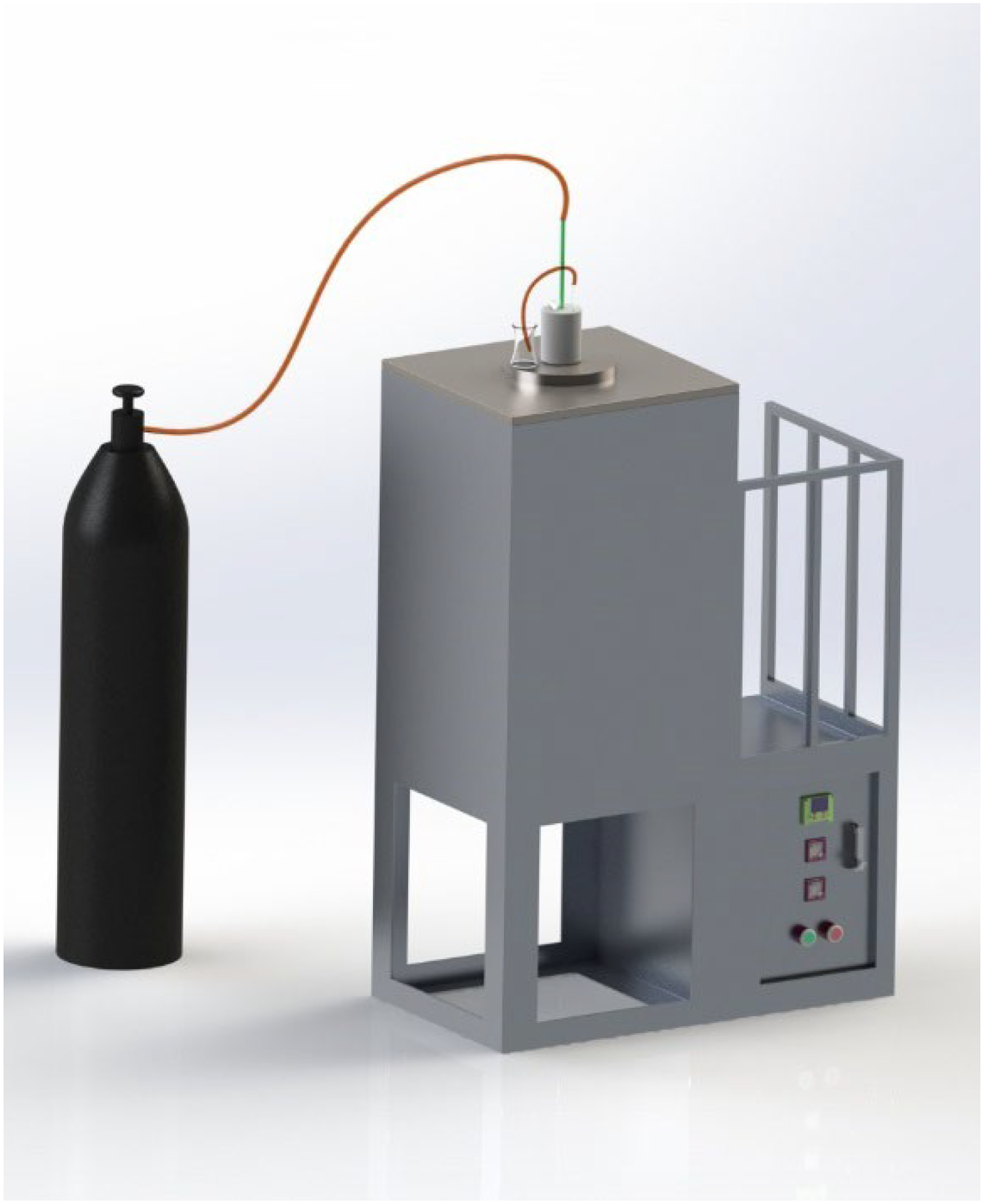
3D view of high-temperature atmosphere furnace.
The experiments used a corundum nozzle to inject CO2 gas, and its high-temperature resistance can ensure the stability of the blowing process. The blowing process may suffer from uneven bubble distribution, which leads to local differences in reaction rates. Future studies may optimise the nozzle layout or introduce dynamic adjustment techniques to improve the uniformity of gas distribution.
The sampling device consists of two main parts: one is a quartz glass tube with an outer diameter of 9 mm and an inner diameter of 5 mm; the other is a syringe with a capacity of 10 mL. These two are interconnected by a section of rubber tubing. To take a sample of molten iron, the air is first expelled from the syringe, after which the open end of the quartz glass tube is immersed in the molten iron and the desired sample is drawn up by pushing the syringe. The rubber hose connection ensures accurate sampling and safe operation. After the sampling operation is completed, the sample of ferro-water in the syringe can be cooled naturally at room temperature. In order to reduce the influence of oxygen in the air on the carbon content of the sample, the skin of the sample taken out is polished, and the sample is taken out from the centre position for subsequent analysis and processing. The following is the sample after sampling (Figure 3(a)) and the sampler's physical (Figure 3(b)).
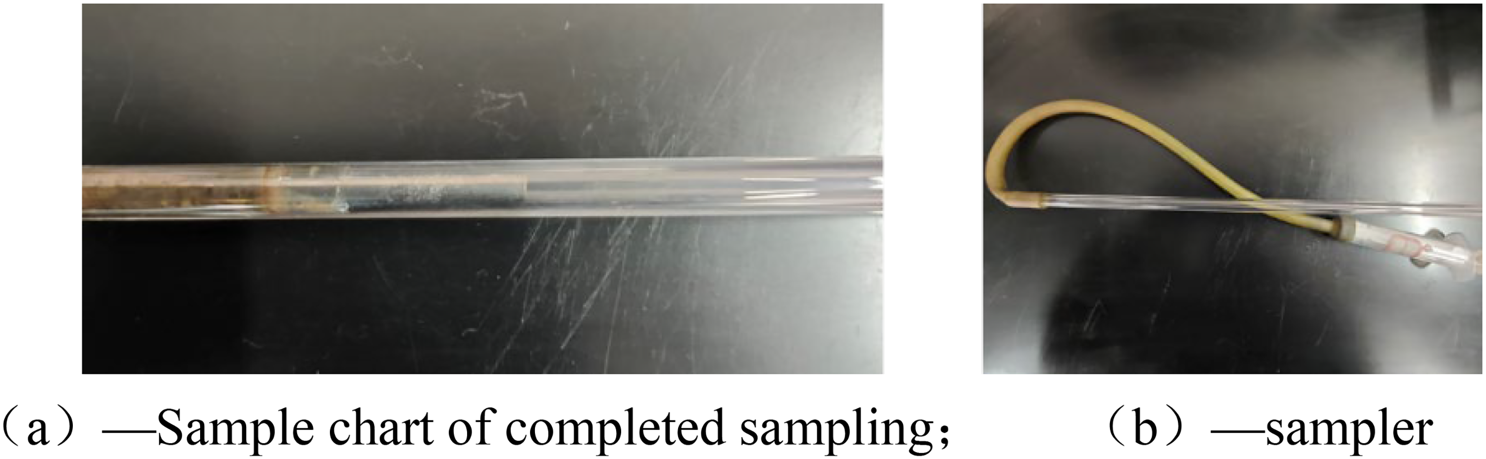
Physical drawing of sampler. (a) Sample chart of completed sampling; (b) sampler.
The carbon content was determined using a CS800 High-Frequency Infrared Carbon and Sulfur Analyzer. First, about 0.2 g of the sample was placed into a crucible. Next, pure tungsten grains were added as a flux, and then the crucible with the sample was placed on a pallet and fed into a high-frequency induction furnace for combustion. The carbon and sulphur analyser used for the test is shown in Figure 4.
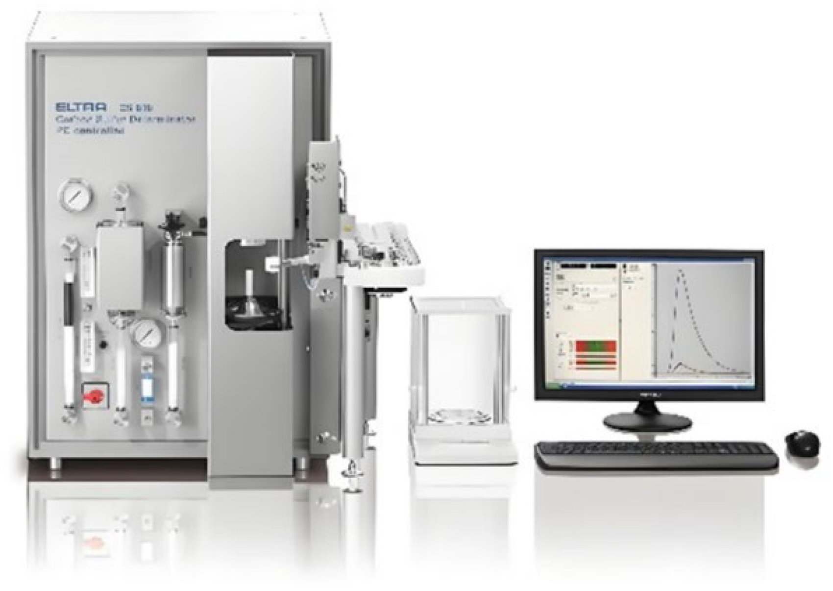
Schematic diagram of the carbon and sulphur analyser.
Experimental steps
Based on the result of dosage calculation, the mass of the required sample is accurately weighed by a high-precision balance, and the sample is placed in an alumina crucible. The alumina crucible is then embedded in a graphite crucible and placed together in a designated position at the bottom of the constant temperature zone of the tube furnace.
A gas-tight system was installed at the top of the tube furnace to prevent the intrusion of external impurity gases into the furnace. Before the experiment was started, the pressure-reducing valve of the high-purity argon cylinder was opened, and argon was injected into the furnace at a flow rate of 400 mL·min−1 and continuously exhausted for 10 min to ensure that the furnace was filled with argon atmosphere, and a gas-tightness test was carried out to verify the system's hermeticity.
Next, set the heating program of the tube furnace to raise its temperature to the melting point of the alloy and maintain the temperature for 30 min to ensure that the alloy material is fully melted.
After the alloy is fully melted, the initial sample is extracted using a sampler and stored after natural cooling at room temperature.
Adjust the tube furnace temperature to the experimental preset value, adjust the protective gas flow rate to 800 mL·min−1, and position the corundum tube below the liquid level of the crucible. Subsequently, open the pressure-reducing valve of the CO2 cylinder and adjust the blowing flow rate according to the experimental design requirements.
During the blowing process, a homemade sampler was utilised to take samples at predetermined positions every 5 min, for a total of five sampling operations, and the sampling was stopped after the blowing process lasted for 30 min.
At the end of the experiment, wait for the tube furnace to cool down to room temperature according to the preset cooling procedure, and then turn off the power to end the experimental operation of the current furnace.
Factsage thermodynamic calculations
The Equilib module in the Factsage 8.2 database was used to calculate the equilibrium state of the reaction between Fe–C solution and CO2 gas, so as to obtain the trend of carbon content during the smelting process. Because the main study of the reaction of carbon in the steel liquid, the steel liquid is simply considered as Fe–C molten steel. The total amount of Fe–C solution is 300 g, respectively, in different gas flow rates, different temperatures, and different initial carbon content to calculate the final equilibrium of the C content in the steel liquid. First, enter the Equilib module, select FactPS, FToxid and FSstel from the database, input the initial steel content and gas flow, select Compound Species and Solution Species, and then input the temperature T. Finally, perform the calculation to get the elemental content of C in the steel solution after the equilibrium of the reaction. Calculate the content of element C in the liquid steel every 5 min sequentially.
Results and discussion
Theoretical analysis
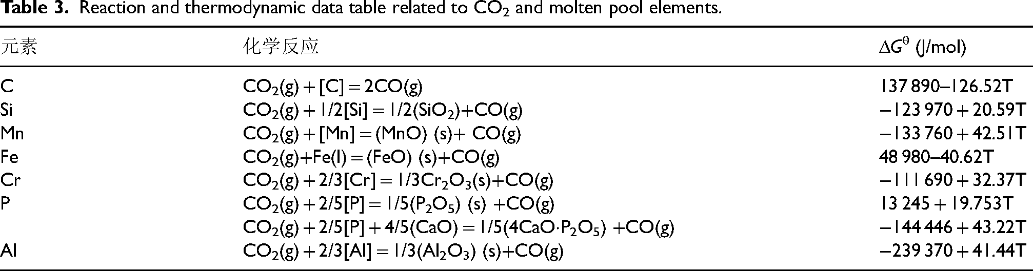
CO2 as a weakly oxidising gas, is relatively stable in general. However, at high temperatures, CO2 can react oxidatively with elements such as [C][Fe][Si][Mn] in molten steel. The standard Gibbs free energies of oxides produced by the reaction of CO2 with the elements in molten steel are shown in Table 3. Then, the variation of ΔGθ of simple oxides obtained by the reaction of CO2 with the elements in molten iron as a function of the temperature, T, was obtained computationally between 1500 and 2000 K, as as shown in Figure 3.
Reaction and thermodynamic data table related to CO2 and molten pool elements.
As shown in Figure 5, the standard Gibbs free energy for the reaction of each element with CO2 at 1500–2000 K is negative, so CO2 can be used as an oxidising agent in the refining process. The slope of the Gibbs free energy curve for the reaction of CO2 with [C] is negative. The slope of the Gibbs free energy curve for CO2 reacting with [C] is negative, and when 1 mol of CO2 reacts with the carbon in the iron water, the yield produces 2 mol of CO and the volume of the gas doubles. The CO gas produced leads to an increase in the volume of gas inside the molten pool, resulting in an increase in the number of bubbles in the molten pool, and eventually, a cluster of bubbles will float up to the surface of the molten pool. This upwelling and movement of the bubbles causes a stirring effect that enhances the stirring capacity of the melt pool. Through stirring, the temperature and composition in the bath are better mixed and uniformly distributed. The formation and upwelling of gas bubbles also promote the transfer of matter and heat, which helps to accelerate the reaction rate and equilibrium in the smelting process.
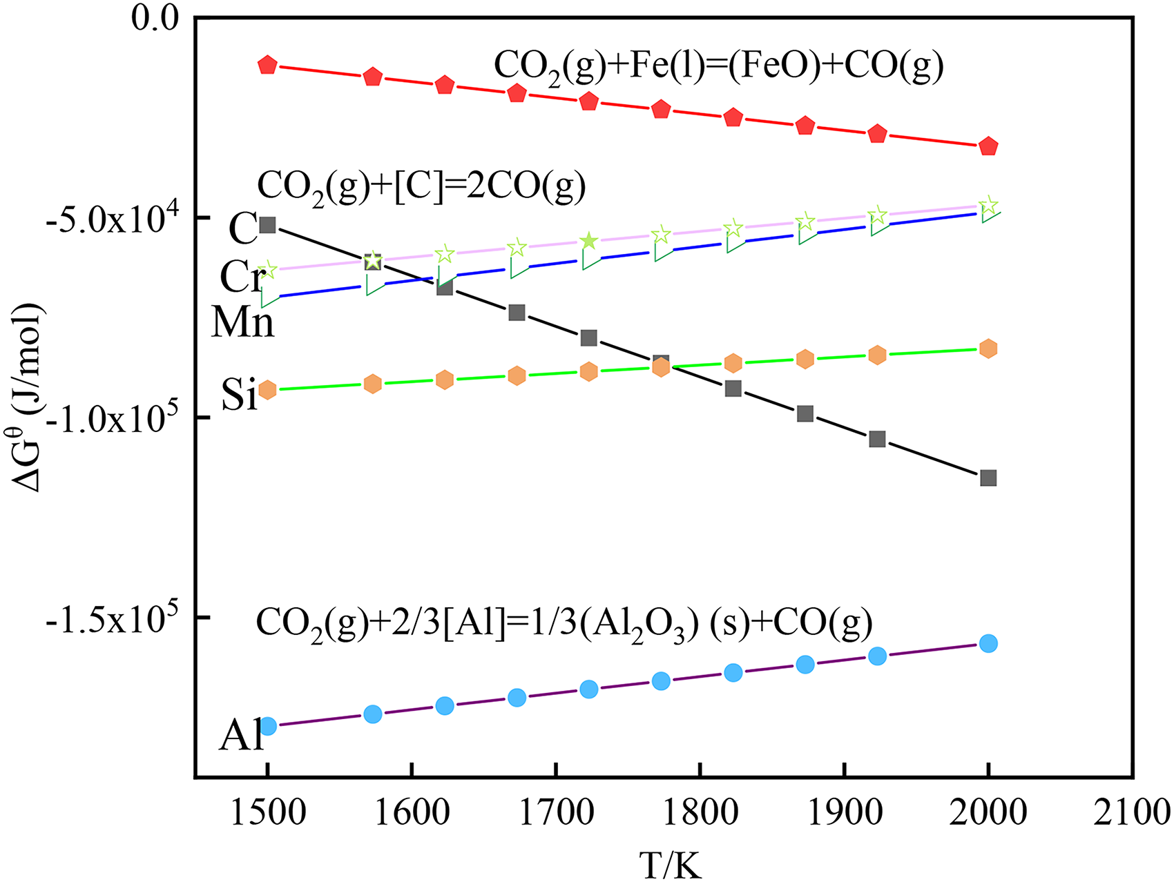
ΔGθ vs. temperature T for the reaction of CO2 with each element.
The chemical reaction process between CO2 gas and Fe–C melt at the refining temperature belongs to the gas–slag–metal three-phase coupling reaction, which mainly includes the following decomposition reaction between CO2 and gas (equation (1)), the equilibrium reaction between CO gas and the carbon and oxygen elements in the melt (equation (2)), the equilibrium reaction between O2 and oxygen elements in the melt (equation (3)), and the equilibrium reaction between oxygenised iron elements in the melt and FeO in the slag phase (equation (4)). The gas-phase members of the system include O2, CO2, and CO, liquid-phase members include [C], [O], and Fe, and slag-phase members are FeO. Bottom blowing process of the blowing gas in the form of individual bubbles or clusters of bubbles in the form of a group of segmented successive entries into the system, the CO2 gas reacts with the members of the system, the meteorological reaction products from the slag–steel interface to escape, and the next CO2 bubbles with the liquid steel successively reacted, the formation of a new equilibrium state, the reaction process is shown in Figure 6.


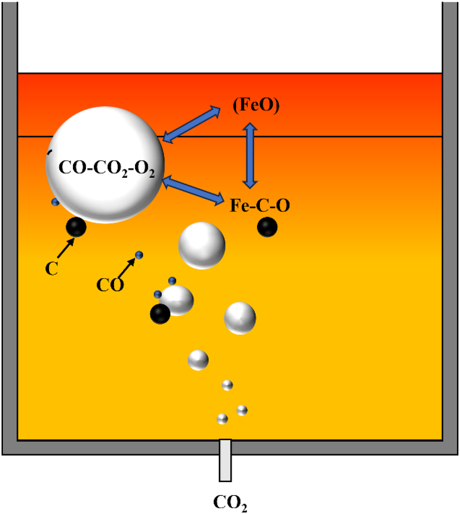
Schematic diagram of the reaction process between CO2 and Fe–C melt.
The influence of reaction time on the decarburisation law of Fe–C alloys
In order to investigate the effect of CO2 on the carbon balance of the melt pool, a 120-min blowing experiment was conducted. The smelting temperature of 1600 °C was selected, and the CO2 blowing flow rate of 40 mL·min−1 was set. As shown in Figure 7, by observing the experimental data, it was found that during such a long blowing process, the carbon content in the molten pool was decarburised as a whole, and finally maintained at a stable level of about 0.11%. This phenomenon suggests that the reaction between CO2 and carbon in the molten steel may have reached an equilibrium state under the condition of prolonged blowing.
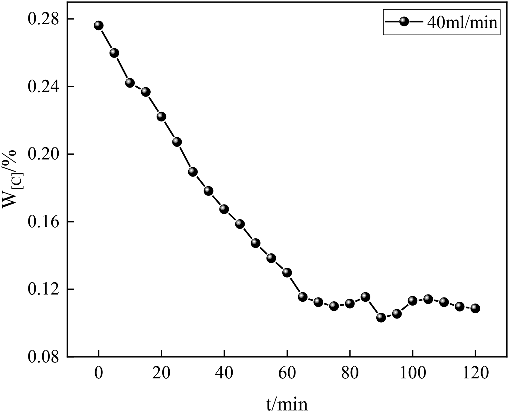
Variation of carbon content in long time blowing.
Influence law of blowing flow rate on decarburisation of Fe–C alloys
During the process of blowing different blowing flow rates of CO2 gas into the Fe–C alloy melt with an initial carbon content of 0.3%, the trend of carbon mass fraction with time is shown in Figure 6. Through the Factsage calculation as shown in Figure 8(a), it can be seen that the carbon content shows an overall decarburisation trend, and the decarburisation rate becomes faster with the increase of the blowing flow rate, although there is a difference in equilibrium carbon content with different blowing flow rates when the final carbon equilibrium is reached, the effect is relatively small in the early stage of the decarburisation reaction. As verified by the thermal state experimental study in Figure 8(b), the carbon content shows a decarbonisation trend, and the gas flow rate has a significant effect on the decarbonisation kinetic process, and the decarbonisation rate is obviously enhanced with the increase of the blowing flow rate.
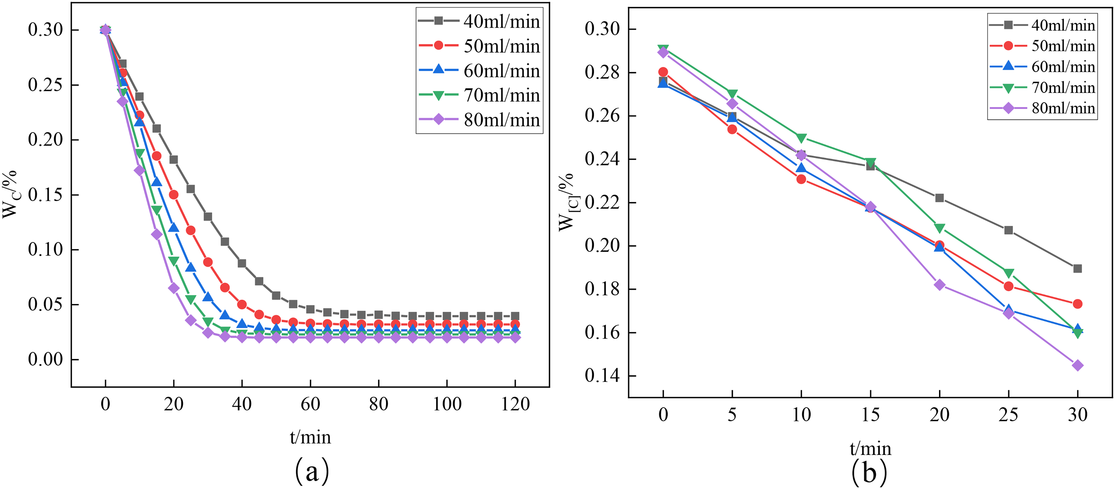
Variation of carbon content at different blowing flow rates.
Under the experimental conditions shown in Figure 9(a), it was observed that the decarbonisation rate was low when the CO2 injection flow rate was maintained at a low level of 40 mL·min−1. However, when the flow rate was elevated to 80 mL·min−1, the decarbonisation rate increased from 0.00275%·min−1 to 0.00491%·min−1, which is a reaction rate enhancement of about 1.78-fold, suggesting that the increase in the injection flow rate is beneficial for promoting the reaction. This phenomenon can be attributed to the lower gas flow rate leading to the inefficient carbon mass transfer in the carbon mass transfer control link. With the increase of CO2 blowing flow rate, the stirring effect of CO2 on the molten pool was enhanced under the high flow rate condition, and the mobility of the molten pool was elevated, which led to a more complete reaction and thus significantly improved the decarburisation effect.
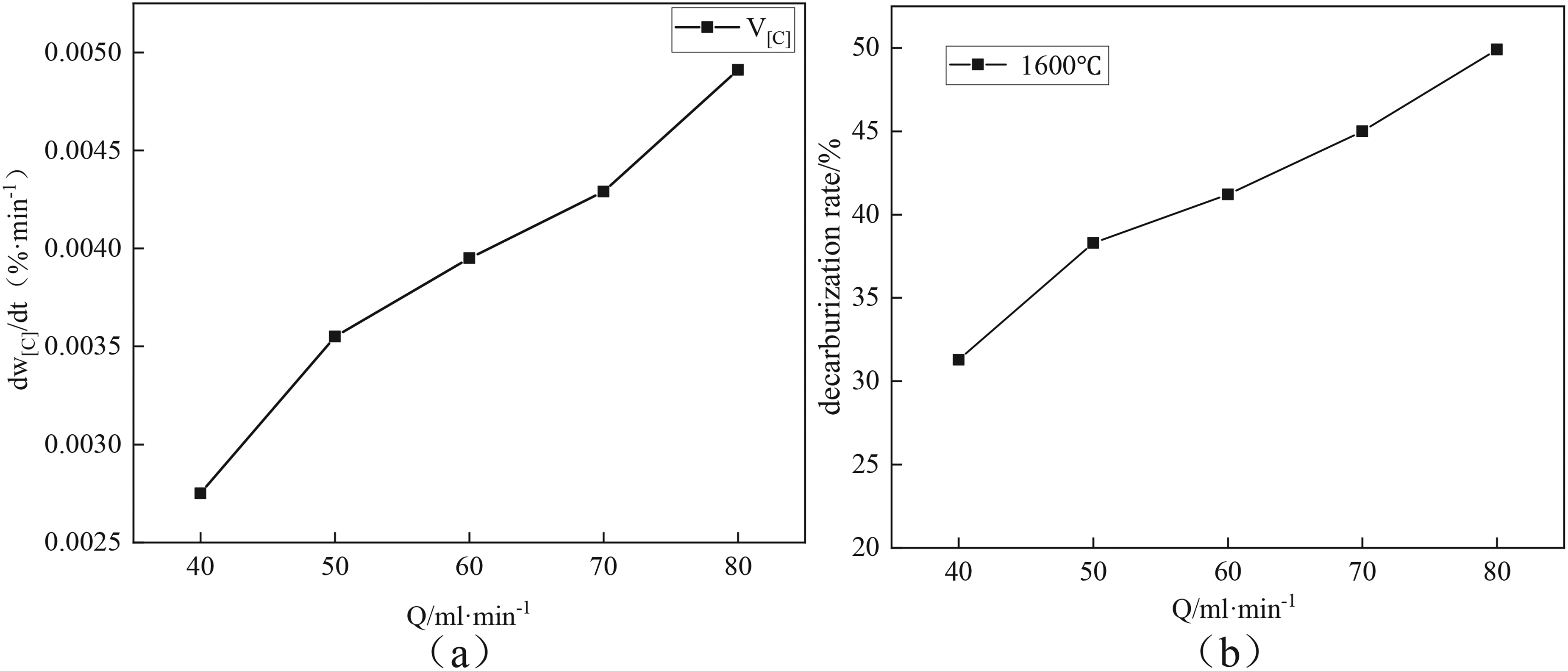
Decarburisation rate and decarburisation rate at different blowing flow rates.
As shown in Figure 9(b), when the blowing flow rate was 40 mL·min−1, the decarburisation rate was only 31.3%, while when the flow rate was increased to 50 –80 mL·min−1, the decarburisation rates reached 38.3%, 41.2%, 45%, and 49.9%, respectively, which confirms that the increase of blowing flow rate effectively enhances the ability of CO2 to oxidise the carbon elements in the molten pool, and thus improves the decarburisation rate.
Temperature effect law on decarburisation of Fe–C alloys
During the CO2 gas injection experiments carried out for the Fe–C alloy melt, a decreasing trend in the mass fraction of carbon with time was observed for an initial carbon content set at 0.3%, as shown in Figure 10. The analysis revealed that the effect of temperature on the reaction rate of elemental carbon removal was relatively small, as shown in Figure 10(a). At the same time interval, although the carbon content remaining after the reaction was slightly lower under higher temperature conditions, this difference was not significant and only showed a slight difference when equilibrium was reached. Further as shown in Figure 10(b), the decarbonisation trend in the hot state experiments coincides with the predicted trend from Factsage software, and the experimental data indicate that the effect of temperature on the decarbonisation rate is not significant.
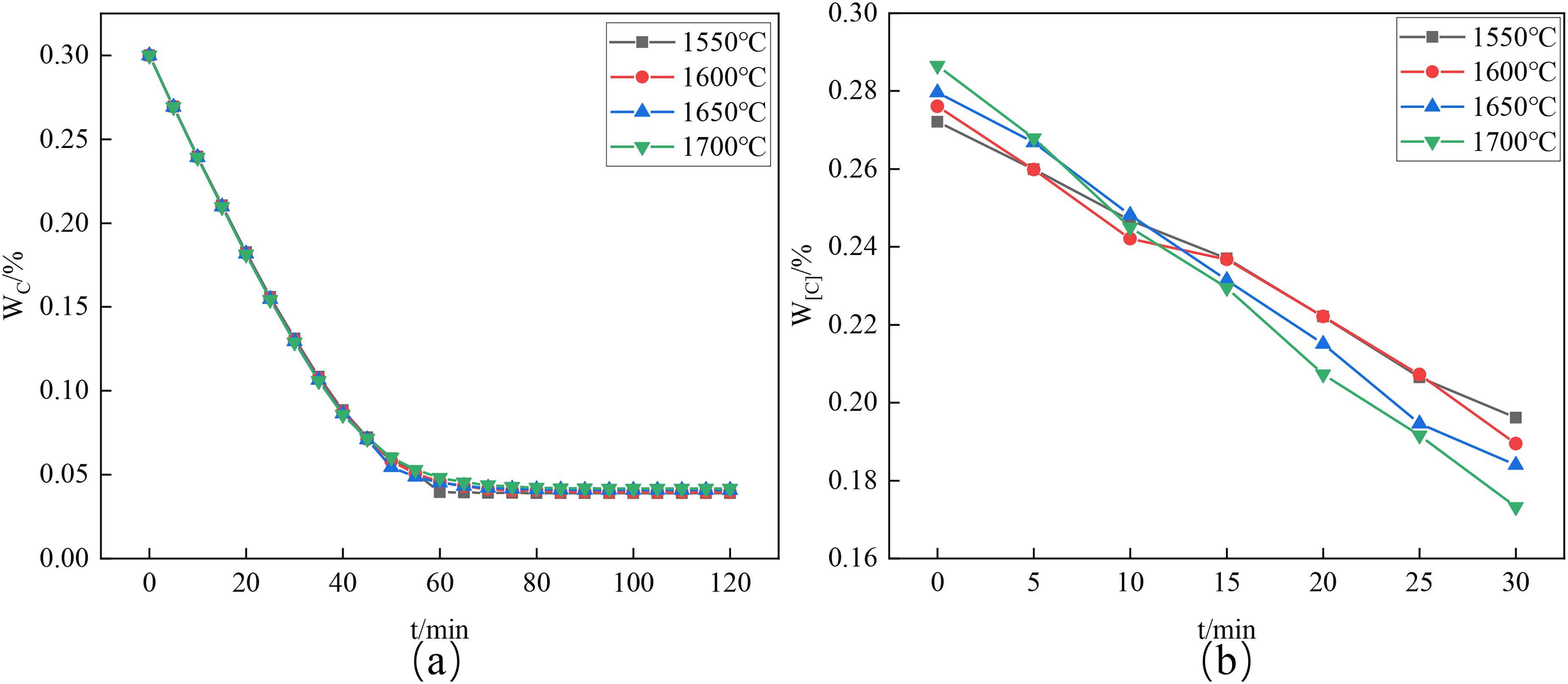
Variation of carbon content with time at different temperatures.
At different steelmaking temperatures, the carbon content in the melt pool decreases as the reaction time increases. As shown in Figure 11(a), the rate of CO2 decarburisation in the melt pool was 0.00257%·min−1 at 1550°C. The rate increased to 0.00275%·min−1 at 1600°C, and then to 0.00332%·min−1 at 1650°C. The rate increased significantly to 0.00375%·min−1 at 1700°C. The rate of CO2 decarburisation in the melt pool decreased with the increase of the reaction temperature to 0.00375%·min−1, and the rate of CO2 decarburisation in the melt pool increased with the increase of reaction temperature.
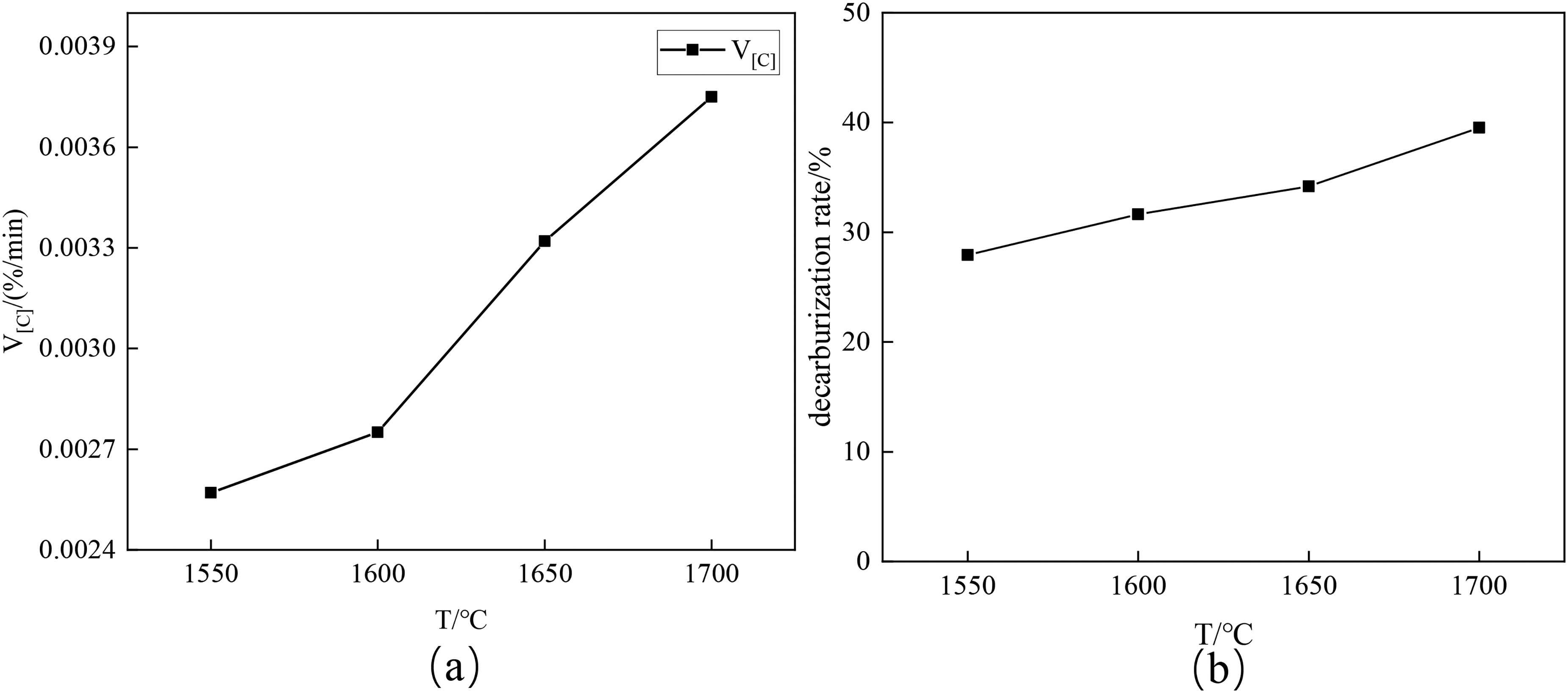
Decarbonisation rate and reaction rate at different temperatures.
As shown in Figure 11(b) at 1550°C, the decarburisation rate was 27.93%, reflecting the low reactivity. The decarbonisation rate increased to 31.36%, 34.19%, and 39.54% when the temperature was increased to 1600°C, 1650°C, and 1700°C, respectively, which was an increase of 11.61% compared to that at 1550°C. As the temperature increases, the occurrence of decarburisation reaction becomes easier, and the tendency of CO2 to react with [C] elements in the melt pool increases.
The involvement of CO2 in the elemental reactions in the melt pool was explored in the theoretical analysis, and the expression for the Gibbs free energy change (ΔG) of the oxidation reaction of elemental carbon ([C]) by CO2 was derived as ΔG = 137 890–126.52 T. The value of ΔG is less than zero in the temperature range of 1550–1700°C (i.e. 1823–1973 K), which suggests that the reaction is a heat-absorbing reaction. In this temperature range, the ΔG value decreased from −92 755.96 to −111 733.96 J, indicating that the increase in the melt pool temperature shifted the reaction equilibrium in the direction of decarburisation, which was favourable for the decarburisation reaction, thus accelerating the decarburisation reaction rate.
Influence law of initial carbon content on decarburisation of Fe–C alloys
As demonstrated in Figure 12(a), by analysing the thermodynamic calculations of the CO2 gas injection process for Fe–C alloy melts with different initial carbon contents, the results show that a decarburisation trend is presented under the condition of maintaining a constant injection flow rate and temperature, however, the difference between the equilibrium carbon contents finally reached is not significant. In the experimental trend of the thermal state presented in Figure 12(b), it can be observed that the overall decarbonisation phenomenon is clearly exhibited when the initial carbon content is in the range of 0.2%–0.5%.
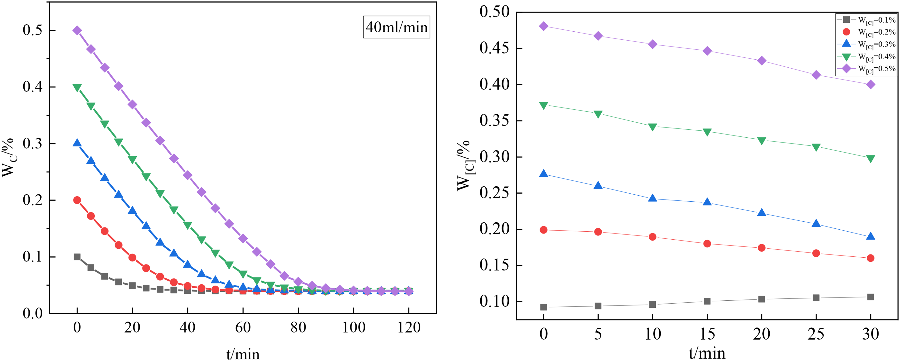
Variation of different initial carbon contents with time.
From Figure 13, it is observed that in the study of the kinetics of CO2 decarburisation reaction in low carbon Fe–C alloy melt, it is observed that the reaction rate is about 0.00136%·min−1 for an initial carbon content of W[C] of 0.2%, whereas the reaction rate is significantly increased to 0.0275%·min−1 when the initial carbon content is increased to W[C] of 0.3%. The corresponding reaction rates are 0.00236%·min−1 and 0.0266%·min−1 with the increase in initial carbon content to W[C] of 0.4% and 0.5%, respectively. It can be seen that with the increase in the initial carbon content, the corresponding reaction rates are 0.00236%·min−1 and 0.0266%·min−1, respectively. W[C] to 0.4% and 0.5%, the corresponding reaction rates were 0.00236%·min−1 and 0.0266%·min−1, respectively, which showed that the overall decarburisation reaction rate showed a slow increase with the increase of the initial carbon content, indicating that the increase or decrease of the initial carbon content had a certain effect on the decarburisation rate of CO2 in the melting pool. This phenomenon can be attributed to the fact that in low carbon steels, the mass transfer capacity of carbon in the decarburisation reaction CO2 + [C] = 2CO decreases significantly due to the low carbon content, resulting in CO2 not being able to react with carbon completely, and thus the lower the carbon content, the lower the reaction rate. This experimental result is consistent with the prediction of the Factsage simulation.
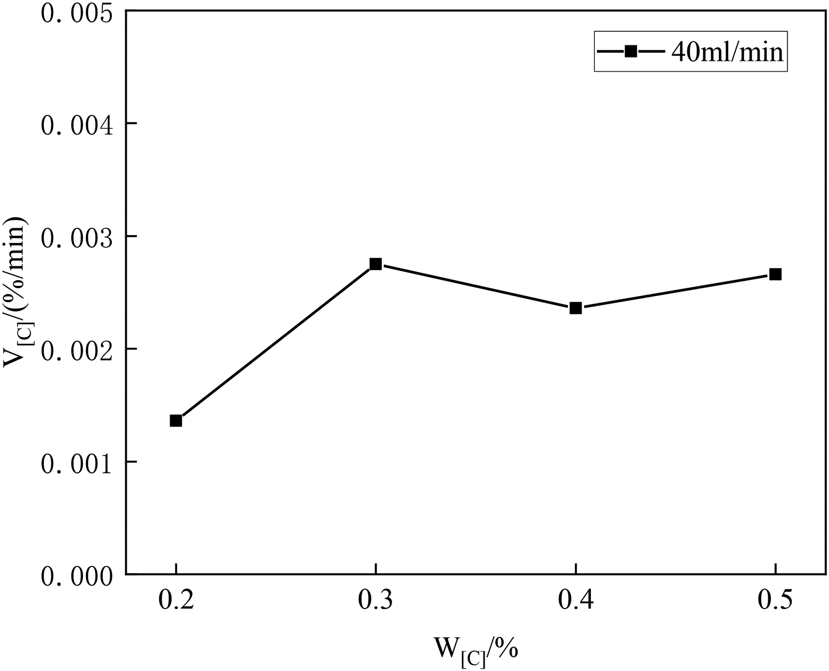
Decarbonisation rate at different carbon contents.
Analysis of CO2 decarbonisation and rate control links
The decarbonisation chemistry of blown CO2 is shown in the following equation.
The process mechanism of CO2 bubbles interacting with [C] in the steel liquid is as follows, as shown in Figure 6:
Mass transfer of elemental C from the interior of the liquid steel to the bubbles. Interfacial reaction occurs at the bubble generation surface. The CO produced diffuses into the bubble and floats up with the bubble.
Since the interfacial chemical reaction rate is very fast at high temperatures, it will not be the rate-controlling link, therefore, the rate-controlling link of CO2 blowing in the low carbon stage is carbon mass transfer or carbon monoxide mass transfer.15–17
In the low carbon stage, if the elemental carbon mass transfer is the reaction rate-controlling link, according to the mass transfer theory, the rate of carbon mass transfer is.
where kdC is the mass transfer coefficient of carbon in steel, m·s−1; A is the surface area of the bubble, m2;
By Higbie's dissolution osmosis theory can be obtained as follows:
16
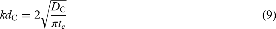


where
From equations (9)–(11), it can be obtained that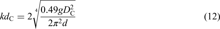
where d is the radius of the bubble, m.
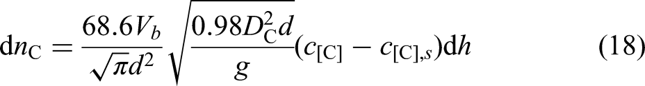
where h is the depth of the melt pool, m.
From equations (8) and (13), we can get
The volume of the bubble Vb (m3) is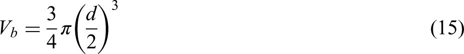
Obtainable
Bringing equations (11)–(13) into equation (10), we get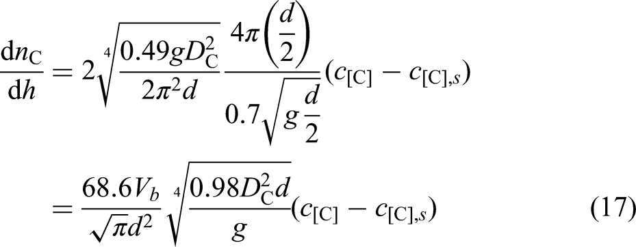
When blowing CO2, if 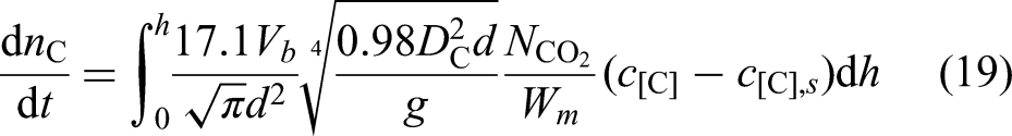
where Wm is the mass of the liquid steel, kg.
Since
where 
Bringing equation (21) into equation (19), we get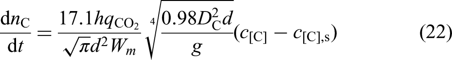
Equation (22) can be transformed into
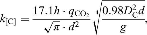
When reaction (7) reaches equilibrium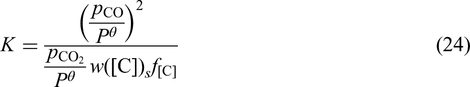
When the carbon content in the melt pool is low, 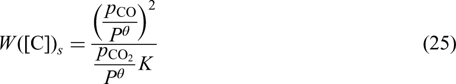
The conversion between molar concentration and mass fraction is given below:
Bringing equations (23) and (24) into equation (21) yields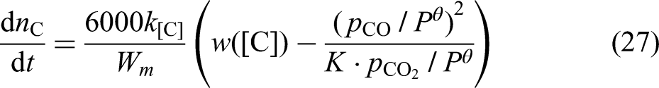
CO gas is produced at twice the rate of elemental carbon through the boundary layer.
Bringing equation (28) into equation (27) and integrating the separated variables yields the following equation: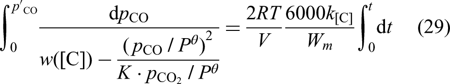
If the elemental carbon mass transfer is a rate-controlled link, the partial pressure of carbon monoxide is calculated as follows as a function of reaction time: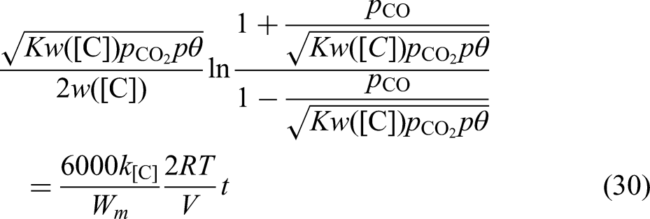
Diffusion coefficient and viscosity are both transport properties of fluids, and there is a similarity in their mechanisms, so the diffusion activation energy is almost of the same order of magnitude as the activation energy of viscous flow, and it can be assumed that there is a certain relationship between the self-diffusion coefficient of the molten metal and the viscosity, which is obtained by Stokes and Einstein based on the theory of fluid dynamics:
The viscosity of the melt is assumed to be 0.002 Pa·s at 1600°C in an iron–carbon alloy with a carbon content of 0.1%–0.5%.
For reaction (7),
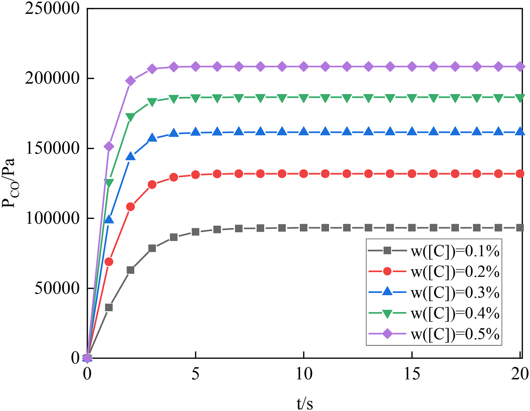
Partial pressure of carbon monoxide vs. reaction time at controlled rates of carbon transfer.
(2) Carbon monoxide mass transfer as a rate-controlled part of the reaction.
If carbon monoxide mass transfer is a rate-controlled part of the reaction, the rate of carbon monoxide transfer is, according to mass transfer theory:
Using the isobaric equation to transform the above equation as follows:
From equation (24), it follows that

After integration, the partial pressure of carbon monoxide is obtained as a function of the residence time of the bubbles in the molten steel as follows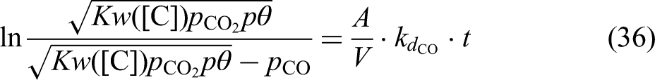
The mass transfer coefficients of the gases are obtained from the permeation theory as follows: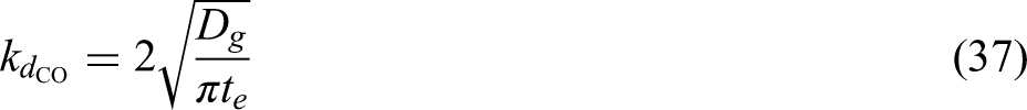
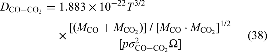
where 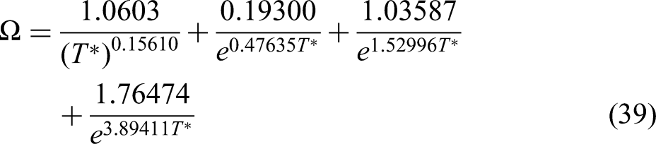
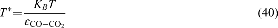


Looking up the table, we can get
Calculate, bring into equation (38), the calculation can be obtained as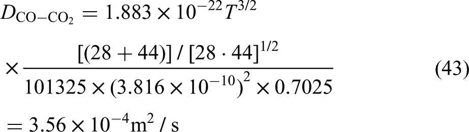
From equations (10) and (11), we have
where
When r = 0.005 m, 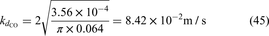
For reaction (7), K = 580 at T = 1873 K. The partial pressure of carbon dioxide is 1.5 × 10⁵ Pa and the radius of the bubble r = 0.01 m,
Analysis of the data in Figures 14 and 15 suggests that if the mass transfer of carbon monoxide is the limiting step in the decarbonisation reaction, the partial pressure of carbon monoxide within the bubble should remain non-equilibrium for a long time. However, calculations show that the decarbonisation reaction rapidly leads to a maximum partial pressure of carbon monoxide within the bubble, indicating that the reaction reaches equilibrium rapidly, thus ruling out the possibility of mass transfer of carbon monoxide as the limiting link. In contrast, if the mass transfer process of elemental carbon is the controlling step, the time required for the partial pressure of carbon monoxide within the bubble to reach its maximum value is much longer than in the case of controlled carbon monoxide mass transfer. It is inferred that the mass transfer of elemental carbon is a key component in determining the rate of reaction during low-carbon decarbonisation. In order to promote the mass transfer of carbon, measures can be taken to increase the CO2 flow rate, in order to improve the molten pool stirring energy density and stirring capacity, thereby accelerating the flow of liquid steel and promoting the decarburisation reaction.
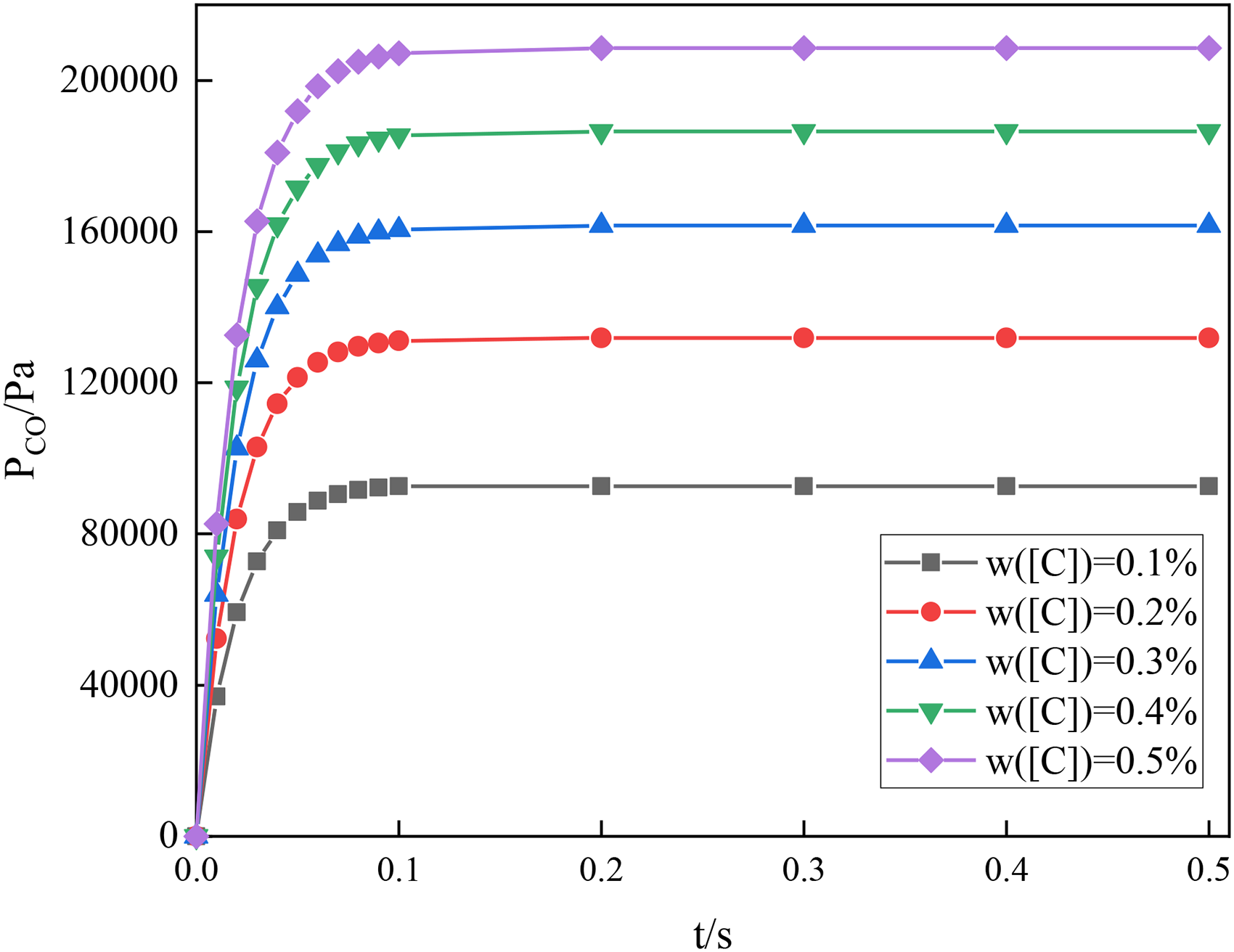
Partial pressure of carbon monoxide vs. reaction time at controlled rate of carbon monoxide.
Conclusions
After CO2 is sprayed into the molten pool under high pressure, CO2 will react with the elements in the molten pool, but the thermodynamic mechanism is not clear. In this paper, the effects of different initial carbon contents, different smelting temperatures, and different CO2 spray flow rates on the oxidation behaviour of the elements in the molten pool in the Fe–C dichotomous system were investigated by Factsage software, theoretical calculations, and high-temperature thermal state experimental system, and the conclusions are as follows:
The oxidation of carbon and iron using CO2 in the melt pool is a heat-absorbing reaction, and the temperature change in the melt pool during the reaction is relatively mild, which helps to avoid drastic temperature fluctuations. CO2 decarburisation is a three-phase gas–slag–gold coupling reaction, and the mass transfer of elemental carbon is a rate-controlling link, especially in low-carbon decarburisation processes. When the initial carbon content of the melt pool exceeds 0.11%, the decarburisation rate accelerates with the increase of initial carbon content. When the initial carbon content is 0.2%, the decarburisation rate is 0.00136%·min−1; when the initial carbon content increases to 0.5%, the decarburisation rate increases to 0.0266%·min−1. When the CO2 blowing flow rate was increased from 40 to 80 mL·min−1, the decarburisation rate increased from 0.00275%·min−1 to 0.00491%·min−1, which is a 1.78-fold increase in the reaction rate. The decarburisation rate increased from 31.3% to 49.9%, indicating that the increase in blowing flow rate significantly enhanced the ability of CO2 to oxidise carbon elements in the melt pool. As the temperature increased from 1550°C to 1700°C, the decarburisation rate increased from 0.00257%·min−1 to 0.00375%·min−1, and the decarburisation rate increased from 27.93% to 39.54%, which was an increase of 11.61%. The increase in temperature promoted the heat-absorption reaction between CO2 and carbon and pushed the reaction toward decarbonisation. By calculating the evolution of CO partial pressure at different initial carbon contents, it was found that the time required for CO partial pressure to reach equilibrium was significantly longer when carbon transfer was the controlling step than in the case of CO transfer control, suggesting that carbon transfer is the rate-limiting aspect of the decarbonisation reaction in the low carbon phase.
Footnotes
Acknowledgements
The presented research was supported by the National Natural Science Foundation of China (52274334).
Declaration of conflicting interests
The authors declared no potential conflicts of interest with respect to the research, authorship, and/or publication of this article.
Funding
The authors disclosed receipt of the following financial support for the research, authorship, and/or publication of this article: This work was supported by the National Natural Science Foundation of China (grant number 52274334).