
Abstract
Hydrogen-based shaft furnaces use hydrogen instead of coke and are regarded as a key route for low-carbon steel production. However, under high-temperature direct reduction conditions, sticking of direct reduced iron may occur, which deteriorates bed permeability and affects production stability. In this study, reduction-under-load tests were conducted to simulate the atmosphere of a hydrogen-based shaft furnace and to investigate the effects of total reduction time, temperature, and coating materials (CaO, MgO, TiO2) on the sticking behavior of vanadium–titanium pellets. The results show that sticking was strongly affected by reduction time at 1100 °C. When the total reduction time reached 2.5 h, the sticking index and sticking strength reached their maximum values of 97.11% and 16.23 N, respectively, and then decreased with further extension of time, while the metallization rate gradually declined. Increasing temperature markedly intensified sticking behavior, whereas the metallization rate changed little. Among the coating materials, TiO2 exhibited the strongest inhibitory effect by forming a dense barrier layer and Fe–Ti–O interfacial products that reduced direct particle contact and suppressed the development of sticking phases.
Keywords
Introduction
Vanadium–titanium magnetite (VTM) is a complex ore rich in strategic metals such as iron, vanadium, and titanium, and possesses extremely high comprehensive utilization value. It is also an important specialty mineral resource in China.1–4 To date, VTM has mainly been processed by blast furnace smelting, which is associated with high carbon emissions and low titanium utilization efficiency.5–9 In order to realize the efficient and environmentally friendly utilization of VTM, researchers have developed a novel smelting route based on gas-based shaft furnace direct reduction. 10 This technology is characterized by low energy consumption, low environmental impact, and high product quality, providing a new pathway for the efficient and low-carbon utilization of VTM resources.11–12 In this process, the smooth descending movement of VTM pellets in the shaft furnace is essential for stable operation. However, during reduction, iron whiskers may form on the pellet surface, and under high temperature and load, low-melting-point substances can be generated, leading to severe sticking between pellets. This phenomenon markedly impairs burden movement and gas distribution within the furnace and has become a critical issue in the steel industry. 13 Previous studies have shown that the sticking behavior of vanadium–titanium pellets during reduction is governed by the combined effects of multiple factors, including reduction time, temperature, load pressure, and reducing atmosphere composition.14–15 In addition, the sticking index (SI) is an important parameter for evaluating the tendency and severity of sticking. Among these factors, temperature exerts a particularly significant influence, and higher temperatures generally correspond to larger SI values, indicating a stronger tendency toward sticking.15–17 Abdel-Halim et al. 18 reported that under an atmosphere of 55% H2 and 36% CO, low load had only a weak influence on sticking behavior, whereas high temperature and high load accelerated the close packing of iron particles and significantly aggravated sticking. Sui et al. 14 investigated the reduction sticking characteristics of VTM pellets and found that increasing temperature greatly promoted sticking behavior, with the SI reaching as high as 99.8% at 1323 K. Microscopic analysis showed that this phenomenon mainly resulted from the excessive accumulation and interweaving of metallic iron on the pellet surface. Di et al. 15 found that when the temperature increased from 750 to 950 °C, the SI of pellets rose sharply from 6.7% to 90.43%, indicating that high temperature promoted iron atom diffusion. Hydrogen was found to significantly inhibit sticking: at 850 °C, increasing the hydrogen concentration from 23% to 43% decreased the agglomeration index from 30.72% to 15.99%. Mechanistic analysis further revealed that hydrogen accelerated reduction and promoted uniform iron deposition, thereby suppressing iron whiskers formation, whereas the dendritic growth of iron whiskers in a carbon-containing atmosphere aggravated sticking. In addition to atmosphere regulation, coating technology has also been demonstrated to be an effective method for inhibiting sticking. Feng et al. 16 reported that the addition of TiO2 significantly reduced the SI from 59.91% to 35.56%. The inhibition mechanism was attributed to the formation of FeTiO3, which hindered the close connection of iron particles and exhibited a more pronounced inhibitory effect at high temperature. Sui et al. 14 systematically compared several coating materials and found that titanium tailings powder showed the best performance, reducing the SI from 99.6% to 12.1% while maintaining a high metallization rate. The inhibition mechanism was related to the formation of the Fe2TiO4 spinel phase in the titanium tailings, which acted as an isolation layer between metallic iron particles and effectively prevented the interconnection of iron whiskers. Guo et al. 19 developed an MgO coating technology and demonstrated experimentally that a 0.1% MgO coating could effectively suppress sticking. This effect was attributed to the formation of a high-melting-point magnesium–aluminum spinel phase, which increased the metallization rate from 58% to above 90%.
Although previous studies have reported the effects of temperature, atmosphere, and coating materials on sticking behavior, the combined evolution of sticking in vanadium–titanium pellets under a hydrogen-rich shaft-furnace atmosphere containing H2, CO, CH4, H2O, CO2, and N2, especially under load-bearing conditions, remains insufficiently clarified. In particular, the respective roles of total reduction time, load-bearing time, and coating chemistry in controlling interface evolution, carburization behavior, and the formation of Fe–Ti–O reaction products still require further investigation. Therefore, this study systematically examines the sticking behavior of vanadium–titanium pellets by reduction-under-load tests under a gas composition representative of a hydrogen-based shaft furnace. Within this framework, the present work focuses on the coupled effects of a complex hydrogen-rich gas atmosphere, controlled loading during reduction, and comparative coating analysis with CaO, MgO, and TiO2, together with SI, sticking strength, metallization rate, X-ray diffraction (XRD), and scanning electron microscope and energy-dispersive spectrometer (SEM-EDS) characterization. On this basis, the evolution of sticking behavior and the inhibition mechanisms of different coating materials are discussed from both macroscopic performance and interfacial microstructure.
Experiment
Experimental materials
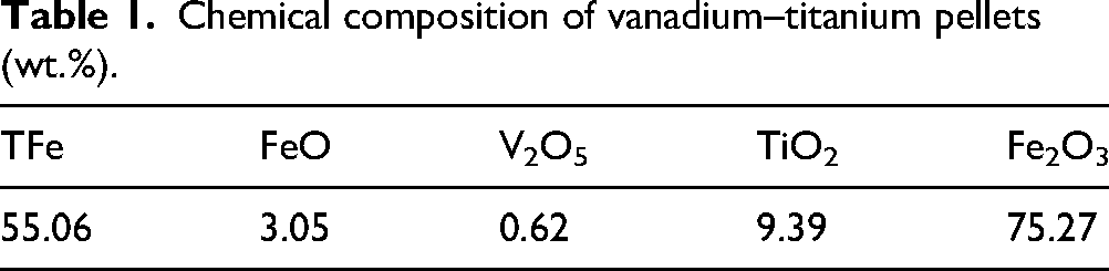
Vanadium–titanium pellets supplied by a Chinese steel enterprise were used in this study. The chemical composition of the pellets was determined, and their phase composition was characterized by XRD. The results are presented in Table 1 and Figure 1. The main phases in the vanadium–titanium pellets were identified as FeTiO3 (ilmenite), MgTiO3 (magnesium titanate), and Fe2O3 (iron oxide).
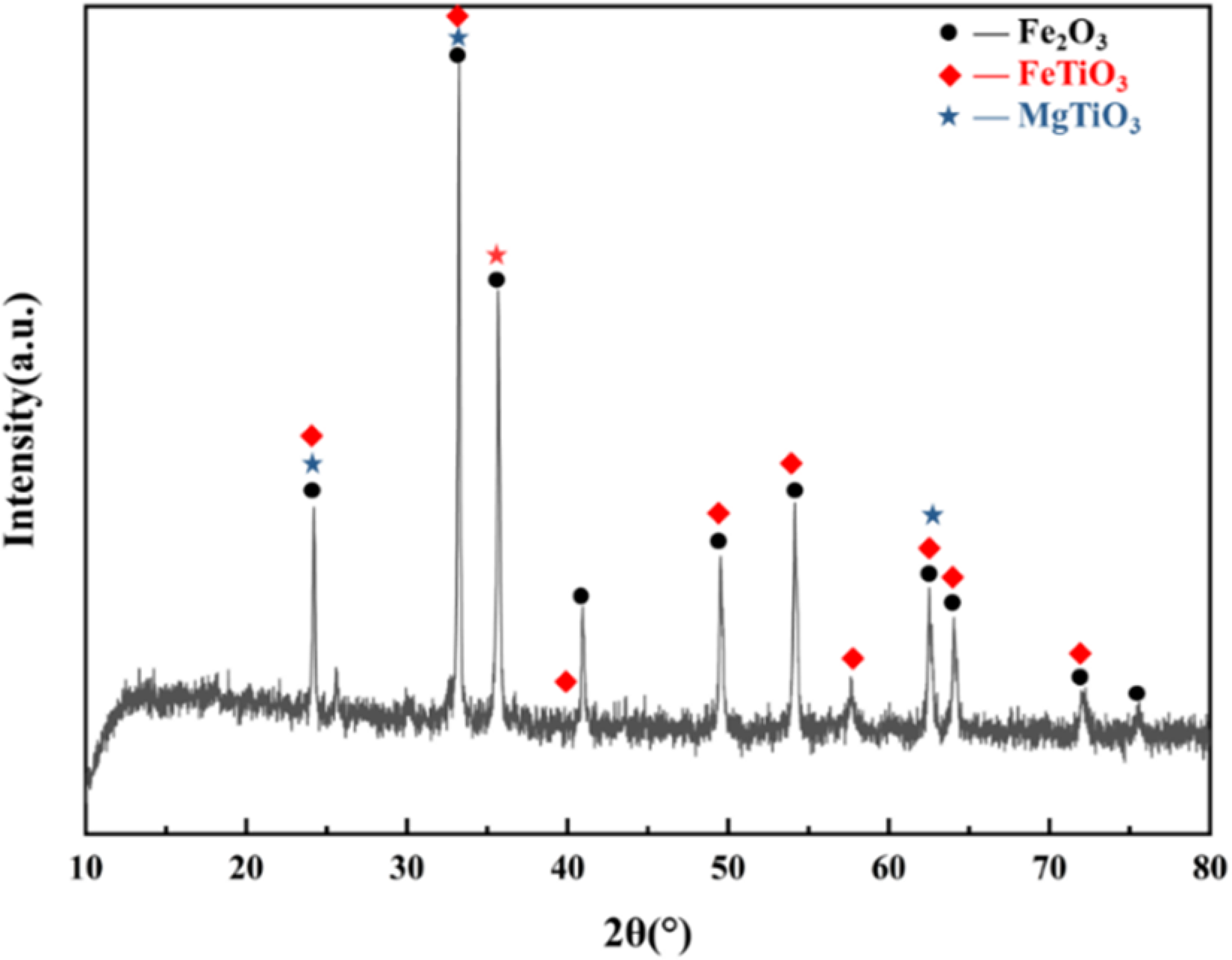
X-ray diffraction (XRD) pattern of vanadium–titanium pellet raw materials.
Chemical composition of vanadium–titanium pellets (wt.%).
Experimental design and methods
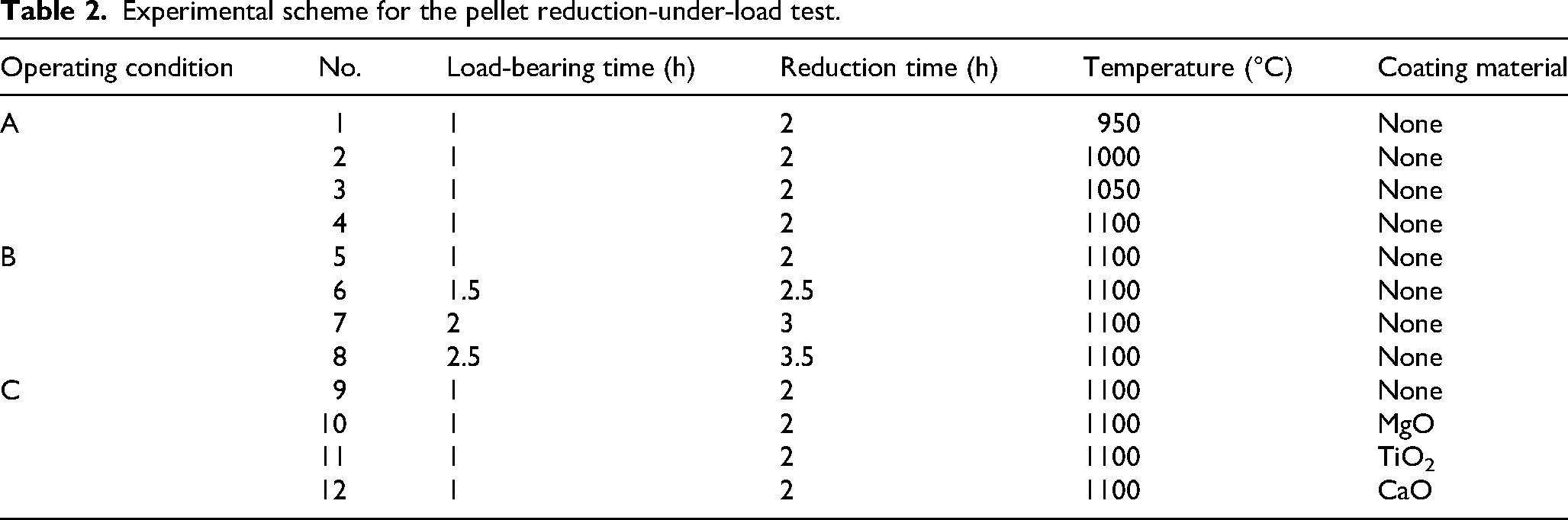
To investigate the sticking behavior of vanadium–titanium pellets under the complex atmosphere of a hydrogen-based shaft furnace, the effects of reduction temperature (950, 1000, 1050, 1100 °C), load-bearing time (1, 1.5, 2, 2.5 h), and coating materials (MgO, TiO2, CaO, none) on the sticking behavior and inhibition performance of vanadium–titanium pellets were systematically studied. Pressurization was initiated 1.0 h after the start of reduction. The specific experimental conditions are listed in Table 2. The total reducing gas flow rate was fixed at 6 L/min, and the gas composition is shown in Table 3.
Experimental scheme for the pellet reduction-under-load test.
Composition of the reducing gas.
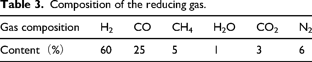
The selected gas composition was designed to approximate the gas environment in the hydrogen-rich reduction zone of a shaft furnace. H2 was used as the dominant reducing gas, whereas CO and CO2 were introduced to reflect the influence of recycled top gas and the coexistence of hydrogen and carbon-bearing species in practical operation. CH4 was included to represent the possible presence of residual methane in reformed gas and to evaluate its influence on carburization under high-temperature conditions. H2O was added to simulate the water vapor generated during reduction, and N2 was used as the balance gas.
The experimental samples consisted of pellets with a particle size of 10–12.5 mm. Prior to testing, the pellets were dried at 105 ± 5 °C for 4 h, and the mass of each sample was controlled at 300 ± 0.30 g. Under operating condition C, the pellets were further treated with a 0.5% coating material by spraying, as shown in Figure 2. The specific process involves mixing the coating powder with deionized water and spraying it onto the particle surface during continuous rolling to achieve the most uniform surface coverage possible. The coating dosage of 0.5 wt.% was selected to ensure effective surface coverage while minimizing changes in bed structure and pellet geometry. Because the coating was deposited by spraying, some local variation in coating thickness was unavoidable; therefore, the inhibition behavior discussed below reflects the combined effect of coating chemistry and practical coating coverage. During the experiment, the samples were heated under a nitrogen atmosphere at a flow rate of 6 L/min, with a heating rate of 10 °C/min to the target temperature, followed by a holding period of 30 min. Subsequently, the reducing gas was introduced for a reaction time of 120 min. A load pressure of 1.4 kg/cm2 was applied after 60 min to simulate the static pressure exerted on pellets within the burden bed. The charging structure adopted an alumina ball-pellet-alumina ball arrangement, with alumina balls of 10–12.5 mm in diameter, as shown in Figure 3. After completion of the reaction, the system was purged with nitrogen. The samples were removed and weighed after cooling to below 100 °C.
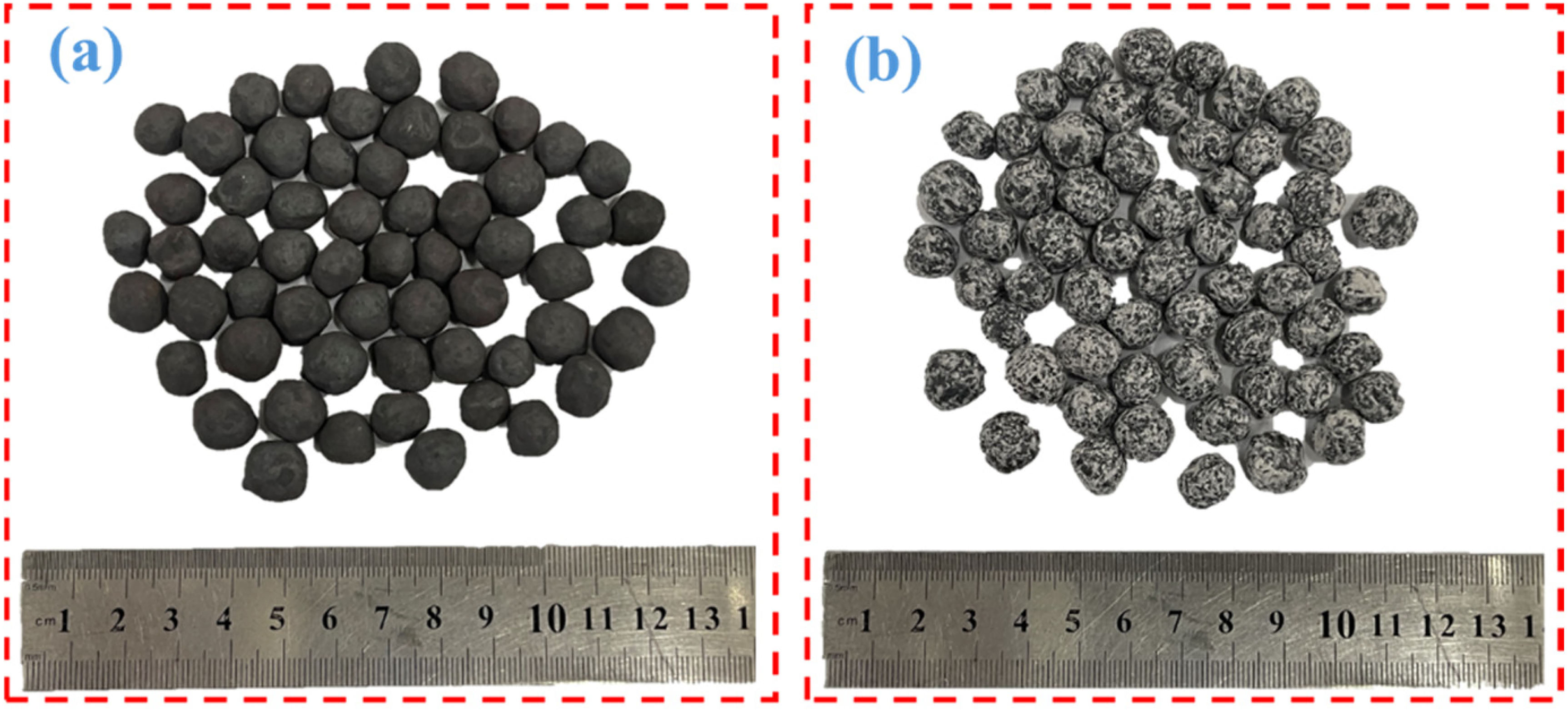
Macroscopic morphology of pellets before and after coating (a)uncoated pellets, (b) TiO2-coated pellets.
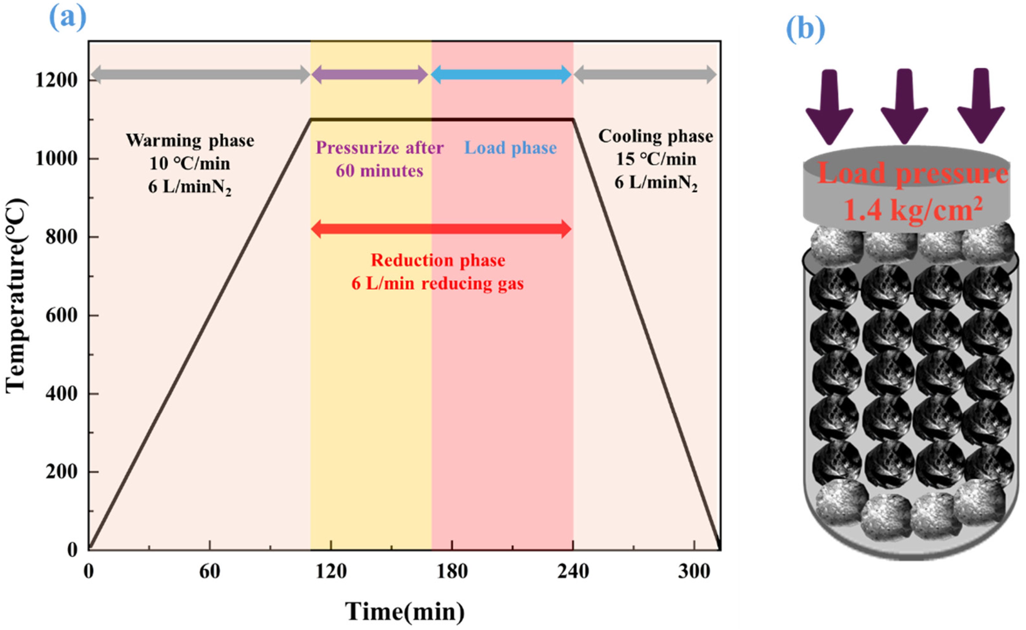
Schematic diagram of the temperature curve and load of the pellet reduction-under-load test (a) heating system, (b) load diagram.
The experimental apparatus is shown in Figure 4. This integrated system combines steam generation, gas mixing, pressurization, and off-gas treatment into a complete reduction reaction platform. The heating system consists of a high-temperature electric furnace equipped with silicon molybdenum rods as heating elements, with a maximum operating temperature of 1600 °C. The steam generation system uses a peristaltic pump to regulate the flow of deionized water. After evaporation, the steam is transported by the other reducing gases acting as carrier gases. The steam is continuously heated and delivered through stainless steel piping to the storage tank to prevent condensation. The pressure control system employs an air compressor to provide a stable pressure of 1.4 kg/cm2, thereby accurately simulating the static pressure environment experienced by the burden layer in an actual shaft furnace.
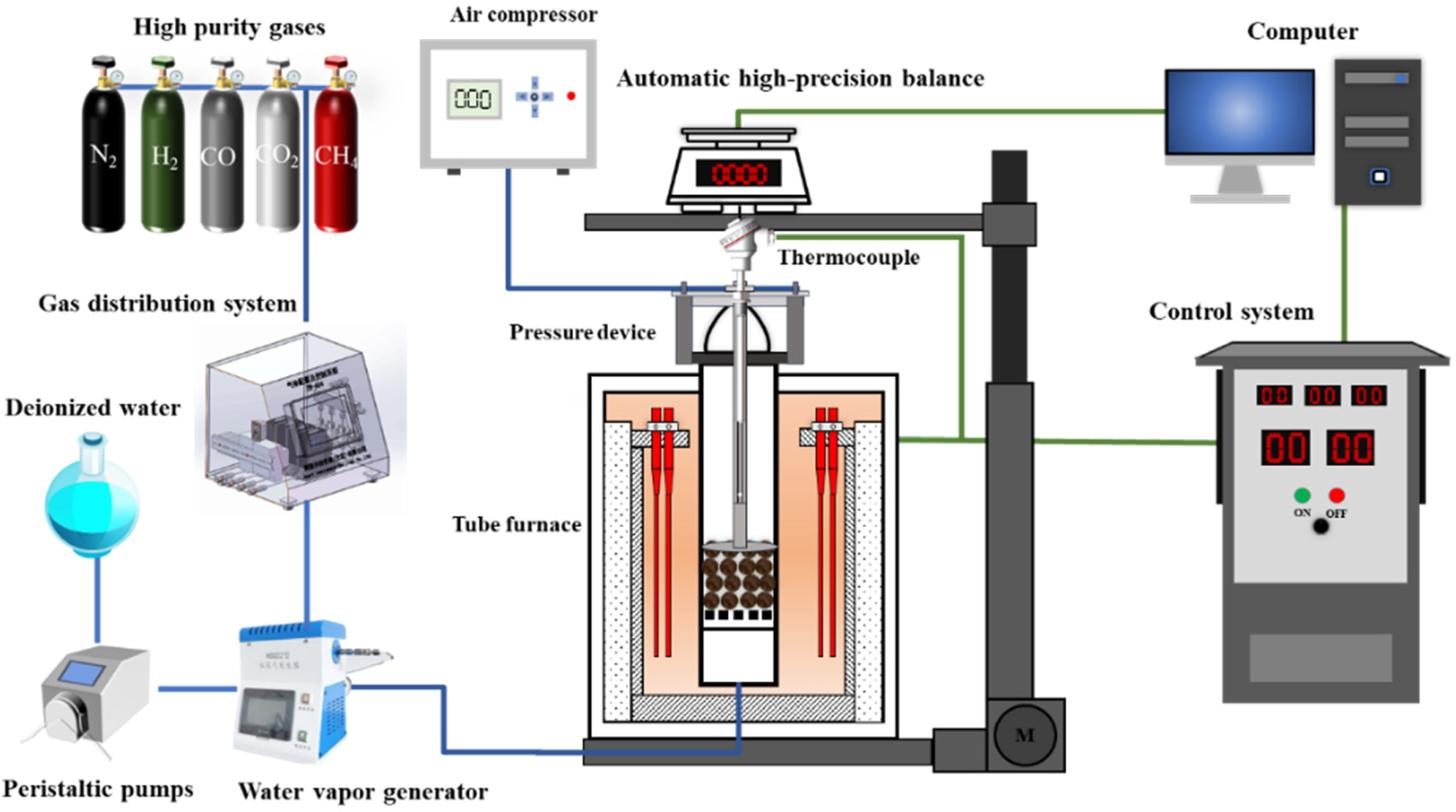
Schematic diagram of experimental device for pellet reduction-under-load test.
Analysis and characterization
The phase composition and morphology of the vanadium–titanium pellets and their reduction products were characterized using an X-ray diffractometer (XRD, X’Pert Pro MPD), a scanning electron microscope (SEM, Nova400 NanoSEM), and an energy-dispersive spectrometer (EDS, IE350 pentaFET X-3).
The metallization rate was determined in accordance with the Chinese national standard “Determination of Reduction Index, Final Reduction Degree, and Metallization Rate of Iron Ore for Direct Reduction Furnaces” (GB/T 24236-2009). The formula for calculating the pellet metallization rate (1) is as follows.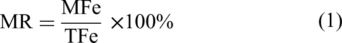
In the formula, TFe is the total iron content in the sample, and MFe is the metallic iron content in the sample.
Since the carbide content in the pellets cannot be measured directly, the total carbon content and free carbon content in the sample are determined through component testing. The carbide content (ωFe3C) after sample reduction and carburization is calculated using the following formula (2)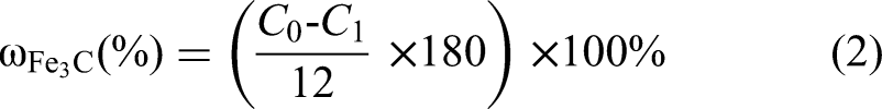
In the equation, C0 represents the total carbon content in the sample, and C1 represents the free carbon content in the sample.
The SI is an important indicator for evaluating the sticking behavior during the reduction process of pelletized ore. A clump of particles containing two or more particles is placed inside a drum (diameter 130 mm, length 200 mm, 30 rpm). Five rotations of the drum are counted as one drum cycle, with a total of three drum cycles performed. The percentage of remaining clusters after each drum rotation is calculated, and the drum rotation count is plotted against the percentage of clusters. The SI is calculated using formula (3).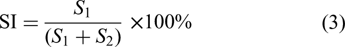
In the formula, S1 is the sum of the masses of the agglomerated pellets, and S2 is the sum of the masses of the dispersed pellets.
The sticking strength was tested using an SH-II-500 digital push-pull tester. Two adhered particles (five sets) were selected and placed on the tensile platform, which moved at a constant speed until the bonded particles completely separated, at which point the test was stopped. This process was repeated five times. The sticking strength was calculated using formula (4).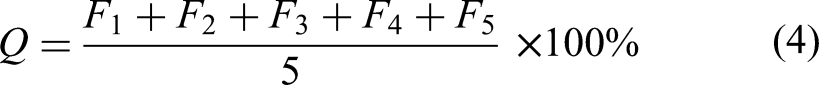
In the formula, F1, F2, F3, F4, and F5 are the tensile forces required to stretch the pellets into a cluster until they disperse.
For sticking strength, five adhered pellet pairs were measured under each condition and the average value was reported. The SI, metallization rate, and phase/microstructural characterization were evaluated under the same experimental procedure for all operating conditions, and the conclusions were drawn from the consistency between the macroscopic indices and the corresponding characterization results. Because the differences between some coating conditions were small, the ranking of coating performance was interpreted together with the microstructural evidence rather than on the basis of a single index alone.
Results and discussion
Effect of reduction temperature on sticking behavior
Under a reducing gas atmosphere consisting of 60% H2, 25% CO, 5% CH4, 1% H2O, 3% CO2, and 6% N2, the effect of reduction temperature on the sticking behavior of pellets after load reduction was systematically investigated in the range of 950–1100 °C at intervals of 50 °C. The experimental parameters were fixed such that a load was applied after 1.0 h of gas reduction, and the reaction was terminated after the load had been maintained for 1.0 h.
As shown in Figure 5(a), reveals the regulatory mechanism of temperature on the SI. As the reduction temperature increased from 950 to 1100 °C, the SI showed a significant positive correlation. No obvious sticking was observed at 950 °C. The SI then increased to 9.49% at 1000 °C, further rose to 11.14% at 1050 °C, and finally exhibited a sharp increase to 32.11% at 1100 °C. The sticking strength showed a similar upward trend with increasing temperature. When the temperature increased from 1000 to 1050 °C, the sticking strength increased by 0.44 N, and at 1100 °C it reached 13.63 N. This behavior can be attributed mainly to the enhancement of interfacial diffusion and solid-state sintering of metallic iron at elevated temperatures. In addition, the sharp increase in the SI at 1100 °C suggests that localized low-melting compounds may also contribute under the present gas atmosphere, although no direct in situ evidence of liquid-phase formation was obtained in this work. Therefore, the effect of possible liquid phases is discussed here as a thermodynamically reasonable contribution rather than as a directly verified dominant mechanism. From the viewpoint of phase equilibrium, the multicomponent FeO–TiO2–SiO2–CaO–MgO-containing system may form locally softened phases in an iron-rich reducing environment, which would facilitate interparticle bonding once severe surface contact has already been established. By contrast, Figure 5(b) shows that the metallization rate remained highly stable over the temperature range of 950–1100 °C, varying only between 95.34% and 95.64%.
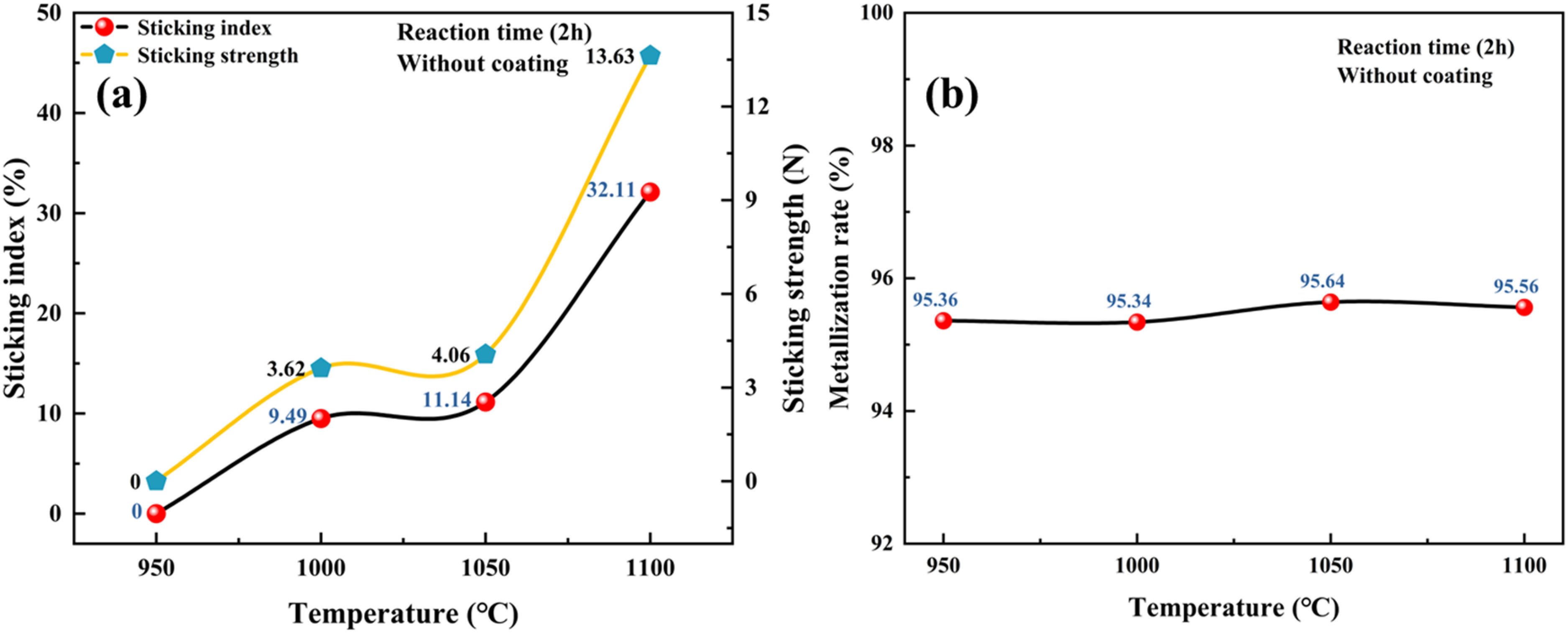
Experimental results of the reduction-under-load test at different temperatures for 2 h: (a) sticking index and sticking strength, (b) metallization rate.
XRD analysis of the sticking interfaces revealed the dynamic evolution of phase composition at different reduction temperatures, as shown in Figure 6. In the lower temperature range of 950–1050 °C, the sticking interface was dominated by metallic iron (Fe), and the characteristic diffraction peak of the Fe (110) crystal plane consistently appeared at 44.674° (2θ, Fe, PDF#06-0696). The gradual narrowing of the diffraction peak with increasing temperature indicates progressive growth in metallic iron grain size. Through surface diffusion and solid-state sintering, metallic iron formed a continuous metallurgical bonding interface at the contact points between pellets. Its oriented crystallization promoted grain growth along preferred directions into fibrous or layered structures, thereby significantly enhancing both the mechanical interlocking and chemical bonding strength between particles. Meanwhile, slag-phase components such as SiO2 and Al2O3 retained their solid bridging effect because of their high melting points. Their synergistic interaction with metallic iron resulted in a steady increase in sticking strength with increasing temperature. When the temperature reached 1100 °C, however, the phase composition changed markedly. A distinct carbide peak corresponding to Fe3C, (PDF#89-2722) appeared for the first time at 43.752° in the XRD pattern. This result indicates activation of the carburization reaction under high-temperature conditions. As the temperature increased, the cracking of CH4 was significantly intensified, resulting in localized enrichment of carbon atoms at grain boundaries. At the same time, the activation energy for carbon diffusion was reduced, thereby promoting rapid migration of carbon along iron grain boundaries and its reaction with metallic iron to form carbides.
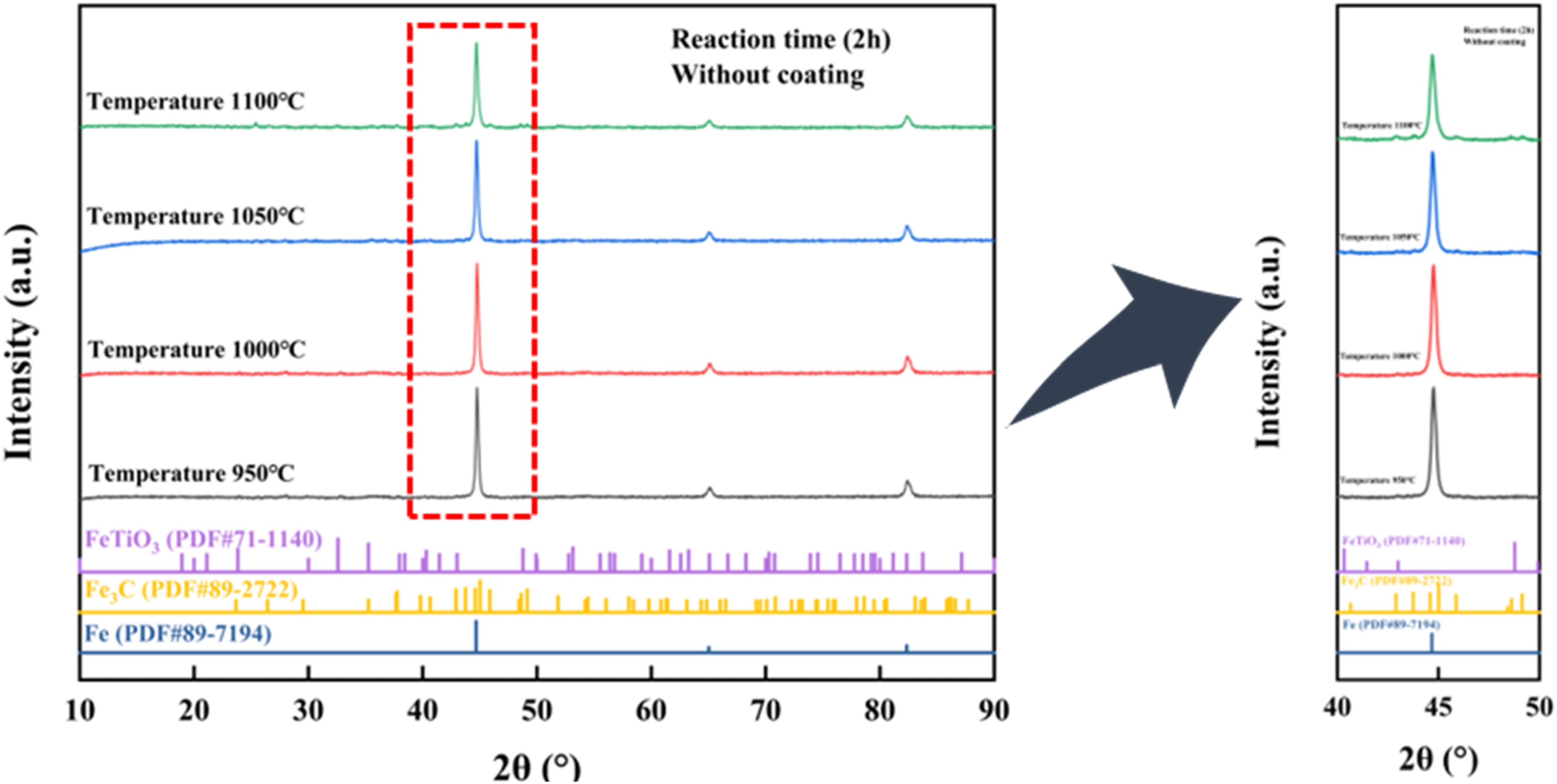
Pellet sticking interfaces at different reduction temperatures: (a) 10°–90° of 2θ, (b) 40° to 50°of 2θ.
Effect of total reduction time and load-bearing time on sticking behavior
Under a reducing atmosphere of 60% H2, 25% CO, 5% CH4, 1% H2O, 3% CO2, and 6% N2 at 1100 °C, the combined effect of total reduction time and load-bearing time on the sticking behavior of pellets during reduction under load was investigated over the range of 2.0–3.5 h at intervals of 0.5 h. In this set of experiments, a load was applied after 1 h of gas reduction, corresponding to total reduction times of 2.0–3.5 h and load-bearing times of 1.0–2.5 h.
Figure 7(a) shows the evolution of the SI and sticking strength with reduction time during the reduction-under-load test. Both parameters exhibited a pronounced trend of first increasing and then decreasing. At a reduction time of 2.0 h, the SI was 32.11%. It then increased sharply and reached a maximum of 97.11% at 2.5 h, after which it dropped abruptly to 16.83% at 3.0 h and further declined to 13.06% at 3.5 h. The sticking strength varied synchronously, reaching a maximum value of 16.23 N at 2.5 h and decreasing to a minimum of 4.47 N at 3.5 h. Figure 7(b) further shows the relationship between reduction time and metallization rate. As the reduction time increased from 2.0 to 3.5 h, the metallization rate exhibited a continuous downward trend, decreasing from 95.56% at 2.0 h to 92.85% at 2.5 h, 91.73% at 3.0 h, and finally 90.08% at 3.5 h. The decrease in metallization rate with increasing total reduction time cannot be attributed to Fe3C formation alone. XRD results show that prolonged reduction also promoted the formation of FeTiO3, which consumed part of the metallic iron. Meanwhile, as sticking became severe, the contact area between pellets increased, and the pore structure at the interface became denser, which could hinder local gas transport. Under such conditions, the coexistence of H2O and CO2 in the reducing gas may promote partial reoxidation of freshly reduced iron in local regions. Therefore, the decline in metallization rate should be understood as the result of the combined effects of carburization, Fe–Ti–O phase formation, and possible local mass-transfer/reoxidation phenomena.
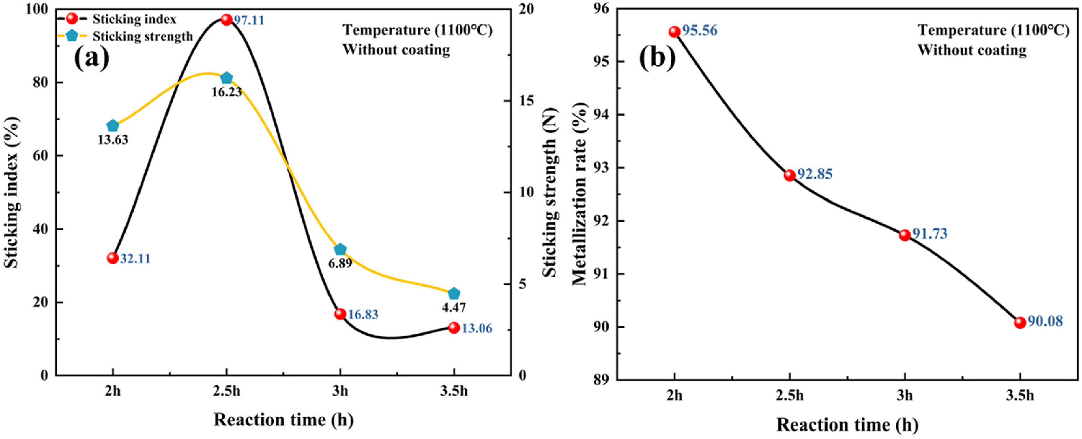
Experimental results of the reduction-under-load test at different total reduction times under the present loading schedule at 1100 °C: (a) sticking index and sticking strength, (b) metallization rate.
To further clarify the changes in metallization rate, the phase composition of the reduction products obtained at different reduction times was analyzed. As shown in Figure 8(a), when the reduction time was 2.0 h, the main phase at the sticking interface was metallic iron (Fe), with its characteristic diffraction peak located at 44.674° (2θ, Fe, PDF#06-0696). When the reduction time was extended to 2.5 h, a characteristic peak of Fe3C (Fe3C, PDF#89-2722) appeared at 43.752°, indicating that the free carbon generated by CH4 cracking reacted with metallic iron to form carbides. When the reduction time increased to 3.0 h, the characteristic peak of FeTiO3 (FeTiO3, PDF#01-075-1212) was detected at 32.588°. With further extension of the reduction time to 3.5 h, the intensities of the Fe3C and FeTiO3 peaks increased significantly, whereas the intensity of the metallic iron peak decreased systematically. These co-evolution characteristics indicate that prolonged reduction promotes the formation of Fe3C and FeTiO3. Both phases consumed part of the metallic iron and thereby contributed to the continuous decline in metallization rate. Specifically, Fe3C formation was associated with the sustained cracking-carburization of CH4 cracking-carburization reaction, while the appearance of FeTiO3 is related to secondary vanadium–titanium in iron–vanadium–titanium compounds during prolonged reduction. This dynamic evolution of phase composition is mutually corroborated with the trend of decreasing metallization rate (Figure 8(b)) at the mechanistic level, revealing the fundamental mechanism by which reduction time influences pellet sticking performance by regulating the balance between the carbonization reaction and the secondary vanadium–titanium process.
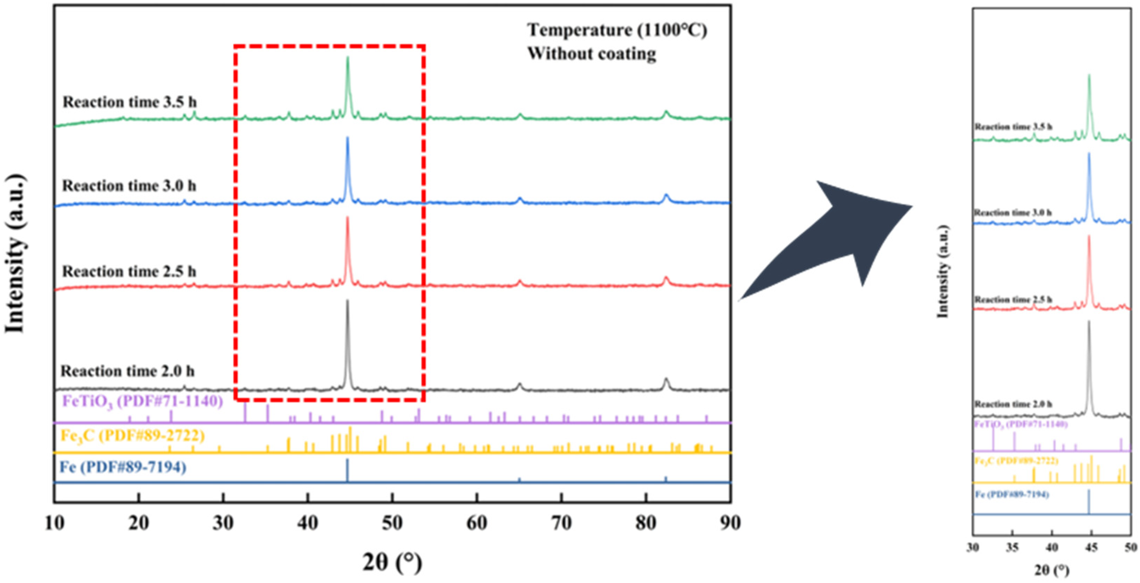
X-ray diffraction (XRD) results of pellet sticking surfaces at different reaction times: (a) 10°–90° of 2θ, (b) 30° to 50°of 2θ.
To further elucidate the microstructural evolution of the bonded interface at different reduction times, SEM-EDS analysis was performed on the reduction products obtained at 1100 °C without coating. The results are shown in Figure 9, where the bond strength exhibits a trend of first increasing and then decreasing with reduction time. During the initial reaction phase (2 h), the pellet porosity was low, and adjacent pellets formed “point-to-point” contacts via metallic iron clusters (Figure 9(a) and (b)). Gas-phase iron atoms diffuse on the surface to form fibrous iron whiskers, while FeO reacts with SiO2 and Al2O3 to form Fe2SiO4 (melting point 1170 °C) and a low-melting-point slag phase of FeO-SiO2-Al2O3 (<1000 °C). The liquid slag phase fills the pores via capillary action, and upon cooling, forms solid silicate bridges (Figure 9(c) and (d)), synergistically enhancing sticking strength. At this stage, metallic iron deposits in a layered, dense structure, with the contact mode transitioning from “point-to-point” to “face-to-face,” significantly increasing connection density. When the reaction is extended to 3.5 h (Figures 9(e) and (f)), over-reduction leads to the formation of FeTiO3 and Fe3C (confirmed by XRD in Figure 8). FeTiO3 occupies the iron sticking points, inhibiting iron atom aggregation, causing the contact surface to contract and the interconnection distance to increase; simultaneously, silicate bridging decreases, resulting in a significant increase in the void volume between pellets. The formation of Fe3C further weakens the continuity of metallic iron, leading to a reduction in the number of contact points and their dispersion. These mechanisms collectively weaken the synergistic sticking effect between iron whiskers and the slag phase, ultimately resulting in a decrease in the SI. These observations indicate that sticking behavior is governed by the dynamic balance between the morphological evolution of metallic iron and the formation of secondary phases.

Scanning electron microscope and energy-dispersive spectrometer (SEM-EDS) analyses of the sticking interface between adjacent pellets with different reduction time: (a, c, e) morphologies of sticking interface between adjacent pellets, (a) 2 h, (c) 2.5 h, (e) 3.5 h, (b, d, f) energy spectra of sticking interface (b) 2 h, (d) 2.5 h, (f) 3.5 h.
Effect of coating materials on adhesion behavior
Under a reducing atmosphere of 60% H2, 25% CO, 5% CH4, 1% H2O, 3% CO2, and 6% N2, the system investigated the regulatory mechanism of coating material types (uncoated, MgO, TiO2, CaO) on the SI of pellets after load reduction. The experiment employed fixed process parameters: after 1 h of gas reduction at 1100 °C, a load was applied, and the reaction was terminated after maintaining the load for 1 h.
As shown in Figure 10(a), all coating materials exerted a significant inhibitory effect on pellet sticking. The SI of the uncoated pellets was 32.11%, whereas those of the MgO, TiO2, and CaO-coated pellets decreased to 2.18%, 2.11%, and 16.69%, respectively. Similarly, the sticking strength of the uncoated pellets was 13.63 N, while those of the MgO, TiO2, and CaO-coated pellets decreased to 3.04, 2.84, and 8.82 N, respectively. These results demonstrate that the coating materials markedly weakened the adhesive interaction between pellets by acting as physical barrier layers. Among the three coatings, TiO2 exhibited the most pronounced inhibition effect, reducing the SI by 93.4% relative to the uncoated sample. By contrast, the inhibition efficiency of the CaO coating was substantially lower than that of MgO and TiO2. Figure 10(b) shows the effect of coating materials on metallization rate. The metallization rate of the uncoated pellets was 95.56%, whereas those of the MgO-, TiO2-, and CaO-coated pellets were 93.61%, 94.42%, and 94.51%, respectively. This decrease can be attributed to the dense isolation layer formed by the coatings, which hindered the inward diffusion and mass transfer of the reducing gases, thereby lowering the local reducing potential and suppressing the deep reduction of iron-bearing vanadium–titanium phases. Notably, while achieving the lowest adhesion index (2.11%), the TiO2 coating exhibited a smaller decrease in metallization rate compared to MgO, demonstrating a selective influence on the reduction process. Therefore, under the present laboratory conditions, TiO2 exhibited the best anti-sticking performance among the examined coatings.
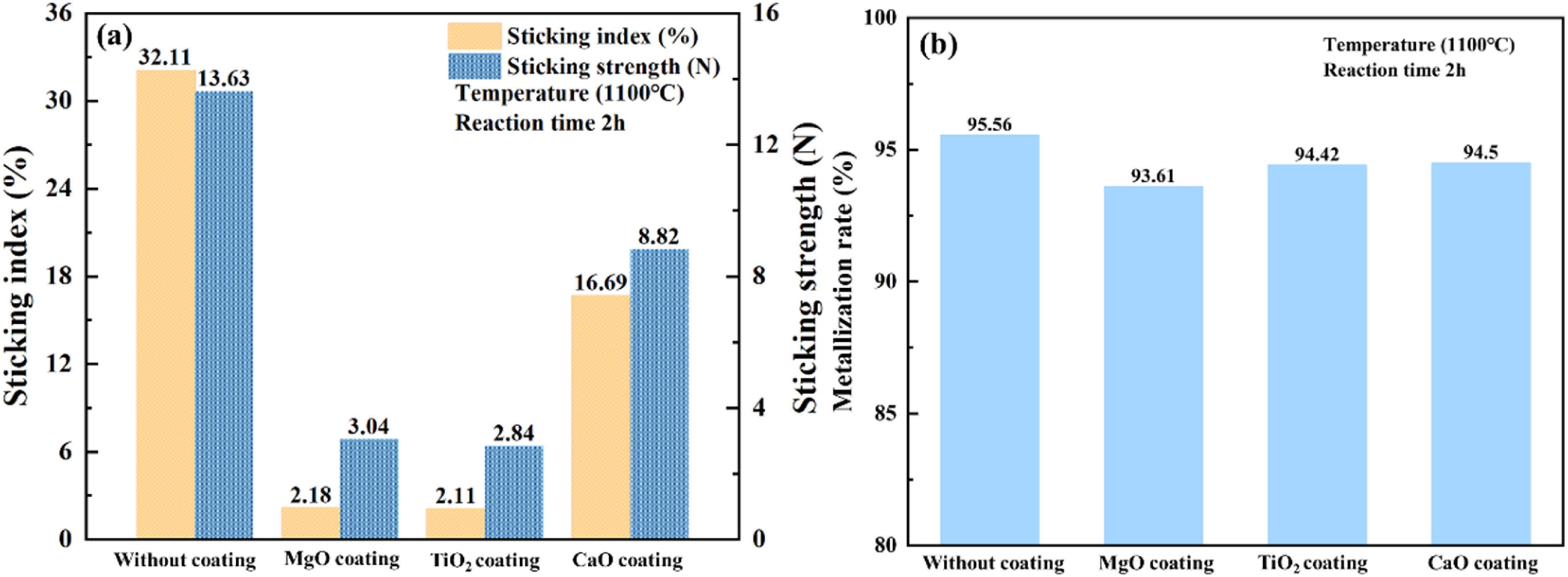
Experimental results of pellet load reduction with different coating materials at 1100 °C: (a) sticking index and sticking strength, (b) metallization rate.
The XRD results shown in Figure 11 further reveal the effect of coating materials on the phase composition of the sticking interface. At a constant temperature of 1100 °C, the sticking interface of the uncoated samples was dominated by metallic iron (Fe, PDF#06-0696), with a characteristic Fe (110) diffraction peak at 44.674° (2θ), and the peak intensity was significantly higher than that of the coated samples. This phenomenon indicates that, in the uncoated system, reducing gases can freely diffuse into the interior of the pellets, promoting the complete reduction of iron–vanadium–titanium compounds and driving the migration of iron atoms toward the particle surface. Under high-temperature thermal activation, iron atoms on the surface diffuse along grain boundaries to form a continuous metallurgical bonding interface. Meanwhile, the grains grow along preferred orientations, forming a dense layered structure that significantly enhances sticking strength through metallic bonding. In addition, slag-phase components (such as SiO2 and Al2O3), which are not effectively inhibited by the coating, still contribute to the formation of low-melting-point liquid phases. This further strengthens the mechanical interlocking effect and leads to an increase in the SI. The introduction of coating materials significantly modifies the interfacial phase composition and sticking behavior through the combined effects of physical barrier formation and chemical regulation. In the CaO- and MgO-coated systems, the XRD patterns, in addition to the peaks corresponding to metallic iron, exhibit characteristic peaks of carbide phases (Fe3C, PDF#89-2722) at 43.752° (2θ). This observation suggests that the coating materials exert a catalytic effect on the carburization reaction. However, the specific mechanism of this catalytic effect requires further research and verification. In contrast, the TiO2-coated system exhibits a distinctly different phase composition. The XRD pattern does not show the theoretically predicted FeTiO3 phase, whose characteristic peak is located at 32.588° (2θ) (PDF#01-075-1212). Although TiO2 showed the best inhibitory effect among the examined coatings, the XRD pattern of the TiO2-coated sample did not always display a distinct FeTiO3 peak. This does not necessarily exclude the formation of FeTiO3 or other Fe–Ti–O reaction products, because such phases may be confined to the local interfacial region, present in low content, or partially overlapped by stronger diffraction peaks from the main phases. Therefore, in this study the formation of FeTiO3 is interpreted mainly on the basis of local interfacial evidence from SEM-EDS together with reaction plausibility. Combined with the microstructural observations, these results indicate that the TiO2 coating achieves the most effective suppression of sticking through several mechanisms. First, its dense structure effectively impedes the penetration of reducing gases into the pellet interior; Second, the relatively low CH4 adsorption capacity of the TiO2 surface suppresses the generation of free carbon, thereby preventing the formation of brittle phases such as Fe3C. According to the sticking mechanism proposed in the work of Qie et al. 20 : in uncoated pellets, iron atoms migrate toward the surface during reduction and form metallic bonding at elevated temperatures, which constitutes the fundamental reason for the increase in the SI. The introduction of coating materials suppresses this process through two main mechanisms. On the one hand, the dense coating hinders the diffusion of reducing gases, thereby reducing the formation of metallic iron. On the other hand, the free carbon generated by CH4 cracking blocks pores within the pellet, further enhancing the inhibitory effect on reduction.
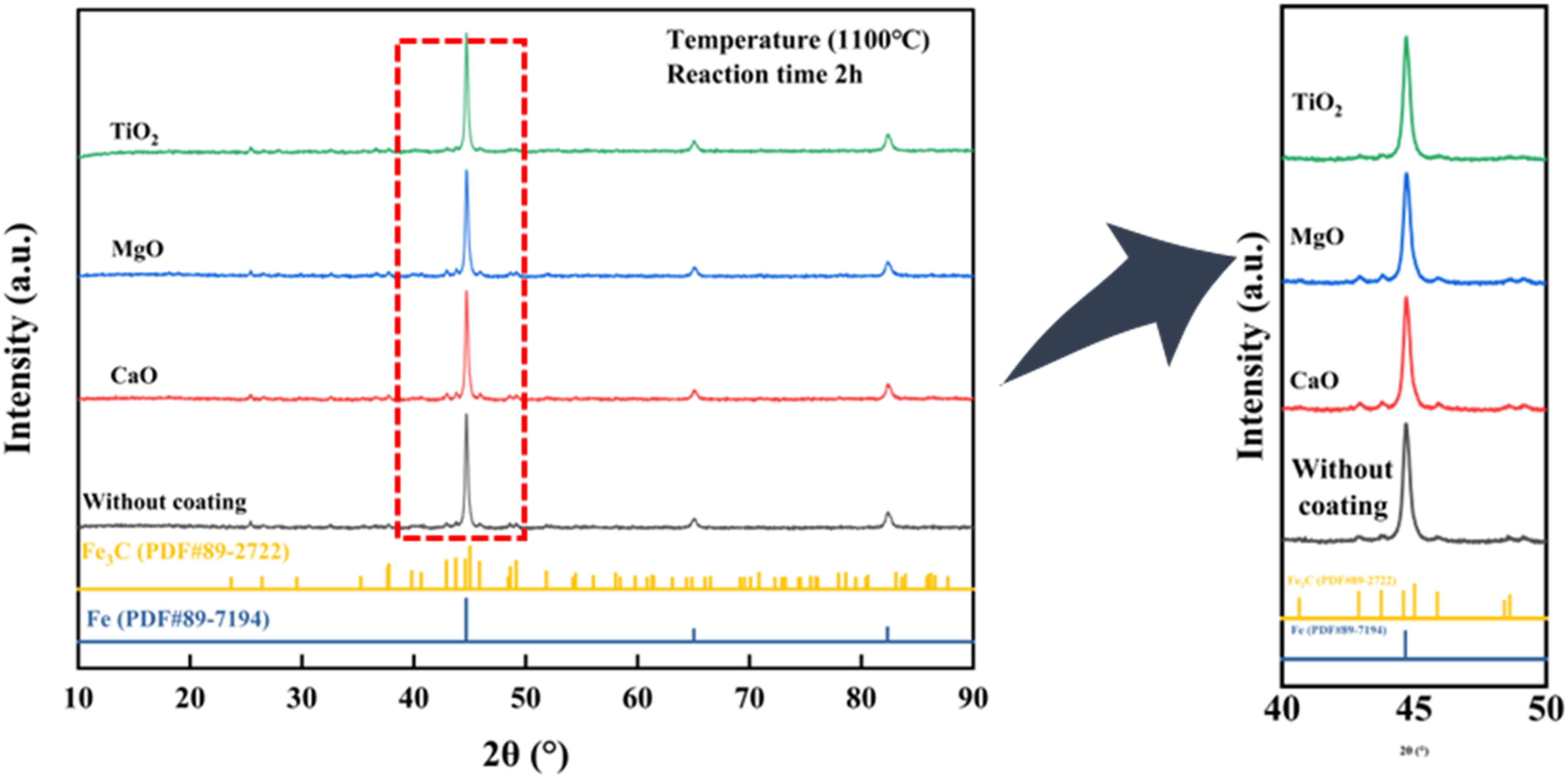
X-ray diffraction (XRD) results of pellet sticking surfaces at different coating (a) 2θ: 10°–90°, (b) 2θ: 40°–50°.
SEM-EDS analysis was employed to investigate the microstructural evolution of the bonded interfaces in the reduced products under different coating materials after reduction at 1100 °C for 2 h, thereby elucidating the intrinsic interfacial morphological evolution and reduction mechanisms during the direct reduction process. The results are presented in Figure 12.

Scanning electron microscope and energy-dispersive spectrometer (SEM-EDS) analyses of the sticking interface between adjacent pellets with different reduction time: (a, c, e) morphologies of sticking interface between adjacent pellets (a) MgO, (c) TiO2, (e) without coating (b, d, f) energy spectra of sticking interface (b) MgO, (d) TiO2, (f) without coating.
After application of the MgO coating, the MgO reagent formed a continuous grid-like layer on the pellet surface (Figure 12(a)), effectively preventing direct contact between metallic iron and the underlying matrix. EDS analysis (Figure 12(b)) shows that Mg is uniformly distributed throughout the interfacial region, indicating that the MgO coating suppresses the surface migration of iron atoms and the growth of iron whiskers through physical separation. In addition, the grid-like structure restricts the penetration of reducing gases, thereby decreasing the extent of reduction and the amount of metallic iron formed. Notably, MgO does not completely suppress carburization, as small amounts of the Fe3C phase are still detected. As an alkaline vanadium–titanium compound, MgO can react with acidic gangue components such as SiO2 and Al2O3 within the pellet to form high-melting-point phases, such as calcium magnesium silicate (CaMgSiO4, melting point approximately 1450 °C) and magnesium aluminate spinel (MgAl2O4, melting point 2135 °C). These high-melting-point slag phases remain solid at 1100 °C and thus effectively inhibit the formation of low-melting-point liquid phases in the FeO–SiO2–Al2O3 system (below 1000 °C), thereby reducing the formation of silicate bridges through capillary action, as evidenced by the markedly decreased Si and Al signal intensities in Figure 12(b). Moreover, the combined effect of the solid slag phase and the MgO coating further suppresses surface roughening of the pellets and weakens mechanical interlocking.
The microstructural characteristics of the sticking interface in TiO2-coated pellets are shown in Figures 12(c) and 12(d). The SEM images reveal that the interfacial region exhibits a typical porous structure, in which the originally continuous and dense distribution of metallic iron particles is disrupted and replaced by discrete, isolated island-like morphologies (Figure 12(c)). EDS elemental mapping (Figure 12(d)) reveals titanium enrichment in the interfacial fracture region, which is consistent with the presence of FeTiO3, indicating that titanium is primarily retained in the iron–vanadium–titanium phase and contributes only minimally to slag-phase formation. The metallic iron particles are tightly encapsulated by FeTiO3. This feature hinders the aggregation of metallic iron and the formation of interconnecting bridges at the sticking interface, thereby reducing both the number and size of contact points between metallic iron particles. Consequently, the SI of the pellets decreases.
In contrast, the microstructure of the uncoated pellets (Figure 12(e)) undergoes pronounced changes, and the sticking interface exhibits a typical point-to-point contact pattern. Fibrous iron whiskers are densely distributed in the contact regions between adjacent pellets. EDS elemental mapping shows the coexistence of metallic iron (Fe) and silicate phases containing Si, Al, and O. Under high-temperature reduction conditions, iron–vanadium–titanium compounds are fully reduced, and iron atoms diffuse via surface diffusion to form epitaxial whisker-like structures. Meanwhile, FeO reacts with SiO2 and Al2O3 to form Fe2SiO4 and low-melting-point FeO-SiO2-Al2O3 slag phases. The liquid slag phase fills pores through capillary action and subsequently forms solid bridges. These two processes act synergistically, leading to a significant increase in the SI.
Based on the experimental results concerning the effects of reduction time, reduction temperature, and coating materials on the sticking behavior of vanadium–titanium pellets in a hydrogen-based shaft furnace, Figure 13 was constructed to illustrate how these factors influence and inhibit pellet sticking during the reduction process.
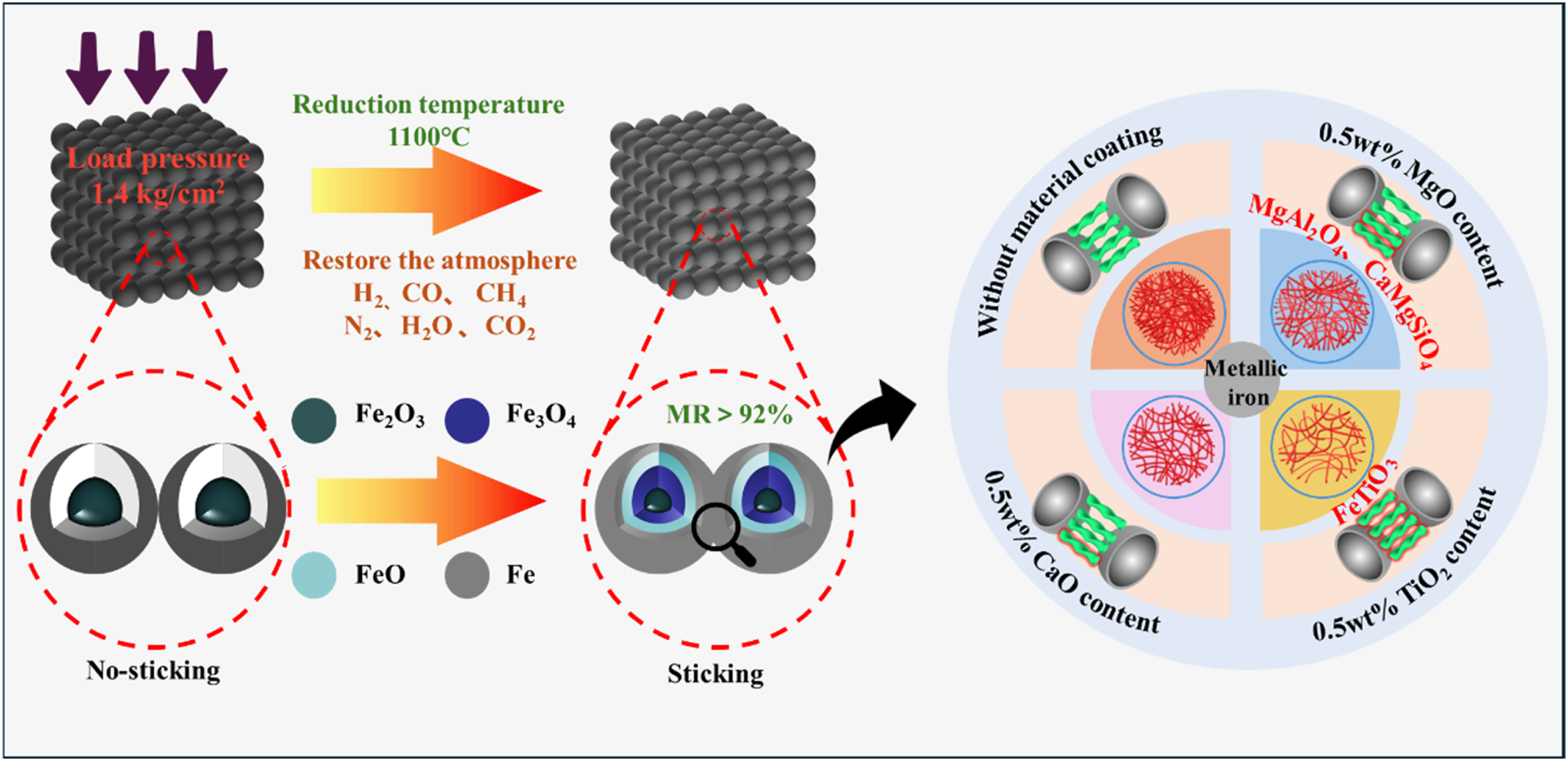
Mechanism of hydrogen-based reduction sticking and inhibition in vanadium–titanium pellet vertical furnaces.
Conclusions
Increasing temperature from 950 to 1100 °C markedly intensified sticking, whereas the metallization rate changed only slightly. The increase in sticking is mainly related to stronger iron diffusion and interfacial sintering; possible localized low-melting phases may also contribute at 1100 °C, but this was not directly verified in the present work.
Under the present loading schedule, the combined effect of total reduction time and load-bearing time strongly influenced sticking behavior. The SI and sticking strength reached maxima at a total reduction time of 2.5 h and then decreased with further extension, while the metallization rate continuously declined because of the combined effects of Fe3C formation, Fe–Ti–O phase generation, and possible gas-transport/reoxidation effects at the sticking interface.
Among CaO, MgO, and TiO2, TiO2 showed the best inhibition effect. Its action is attributed to the formation of a relatively dense barrier layer and local Ti-containing reaction products, probably including FeTiO3, which hindered direct iron-to-iron contact and suppressed the formation and propagation of sticking bridges.
The ranking of coating performance should be interpreted together with the microstructural evidence, because the difference between some macroscopic indices is limited. Further work should quantify coating thickness distribution, experimental variability, and the thermodynamic conditions for local liquid/softened phase formation.
Footnotes
Acknowledgments
The authors gratefully acknowledge the financial support from the National Natural Science Foundation of China, the Natural Science Foundation of Chongqing, and the Chongqing Municipal Education Commission. The authors also thank the Low-Carbon and Intelligent Metallurgy Research Team of the School of Metallurgy and Power Engineering, Chongqing University of Science and Technology, for providing experimental facilities and technical support.
Funding
The authors disclosed receipt of the following financial support for the research, authorship, and/or publication of this article: This work was supported by the Chongqing Natural Science Foundation Innovation Development Joint Fund (CSTB2024NSCQ-LZX0052), Chongqing Municipal Education Commission Science and Technology Research Project (KJZD-M202501503), Science and Technology Innovation Key R&D Program of Chongqing, China (Grant No.CSTB2024TLAD-STX0009), and the State Key Laboratory of Advanced Metallurgy, University of Science and Technology Beijing (USTB) (Grant No. KF24-02).
Declaration of conflicting interests
The authors declared no potential conflicts of interest with respect to the research, authorship, and/or publication of this article.