
Abstract
This work deals with an analytical linear coupled model describing the integrated aero-hydrodynamics of floating offshore wind turbines. Three degrees of freedom (platform surge, platform pitch and rotor azimuth) were considered with the goal of building a reduced-order model suitable for being integrated in control design algorithms as well as to be used for a straightforward evaluation and comprehension of the global system dynamics.
Introduction
Within last years, offshore wind power has been recognized as a high potential source of renewable energy, with different research projects currently being developed to make possible and cost-effective the deployment of multi-megawatt wind turbines in deep waters. However, several technical and scientific challenges arise when designing a floating wind turbine. Platform motion causes the rotor to operate under unsteady flow regimes (Bayati et al., 2017b) which result in variable aerodynamic loads. Moreover, the interaction between the platform rigid-body motion-modes and the wind turbine controller makes the traditional control strategies, commonly used to regulate power in high winds, not directly applicable.
Recently, dedicated numerical tools were developed to support the design of floating wind turbines. These codes are usually capable of replicating the complex aero-hydrodynamic loads experienced by the floating structure and are used for high-fidelity time-domain simulations. Nevertheless, reduced-order models are needed: by describing only the most significant wind turbine degrees-of-freedom (DOFs) in a control design perspective, it is possible, even in the early design stages, to relate more clearly the effect of the wind turbine controller action onto the floating offshore wind turbines (FOWT) dynamics and optimize the overall system design. Finally, reduced-order models are helpful for scale model testing activities, where they can be used to clarify the effects of a scaled environment on the global closed-loop response of the floating wind turbine.
Linear coupled model
A reduced-order linear coupled model was primarily designed by the authors for solving control design issues related with the implementation of a power control algorithm on a 1/75 scale model (Bayati et al., 2016, 2017, 2017) of the DTU 10 MW reference wind turbine (RWT; Bak et al., 2013) to be used for hybdrid hardware-in-the-loop (HIL) wind tunnel tests (Bayati et al., 2017). The model describes the floating wind turbine dynamics focusing on the interaction between rotor and the along-wind platform rigid-body motion-modes, surge
where vector

where

Reduced-order model scheme and conventions.
Linearized platform loads
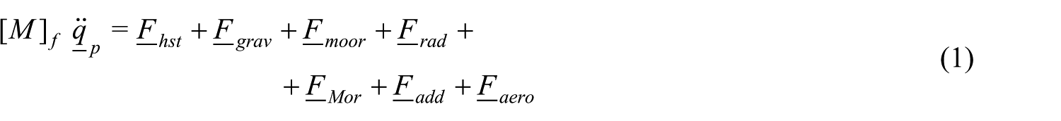
It is possible to get a linearized representation of the floating wind turbine from Taylor expansion of equations (1) and (2) in the neighborhood of any steady-state operating conditions defined for the nonlinear system. The first three terms on the right-hand side of equation (1) represent the restoring loads due to buoyancy, gravity, and the mooring system of the floating platform. The corresponding forces can be expressed as


The first term on the right-hand side of equations (3) to (5) represents, respectively, the hydrostatic, gravitational and mooring line loads that define the static equilibrium position
The time-varying pressure field associated with the platform oscillation in the absence of incident waves defines the radiation loads

where

where the
Additional damping terms are introduced in the model by
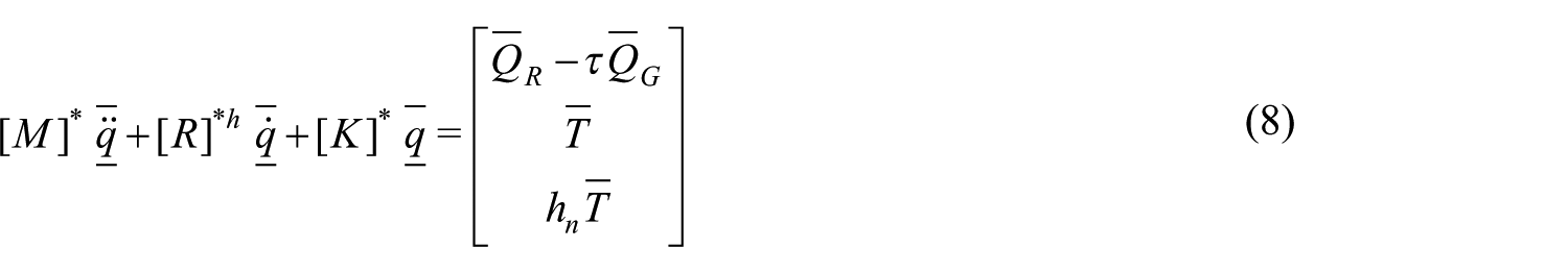
Equivalent mass, damping, and stiffness terms resulting from the linearization of platform loads are summed to the floater and drivetrain structural properties giving the equivalent second-order system of equation (8)
where

defines an infinitesimal variation of the system DOFs (
Linearized aerodynamics
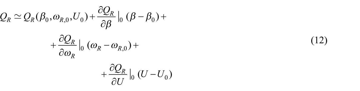
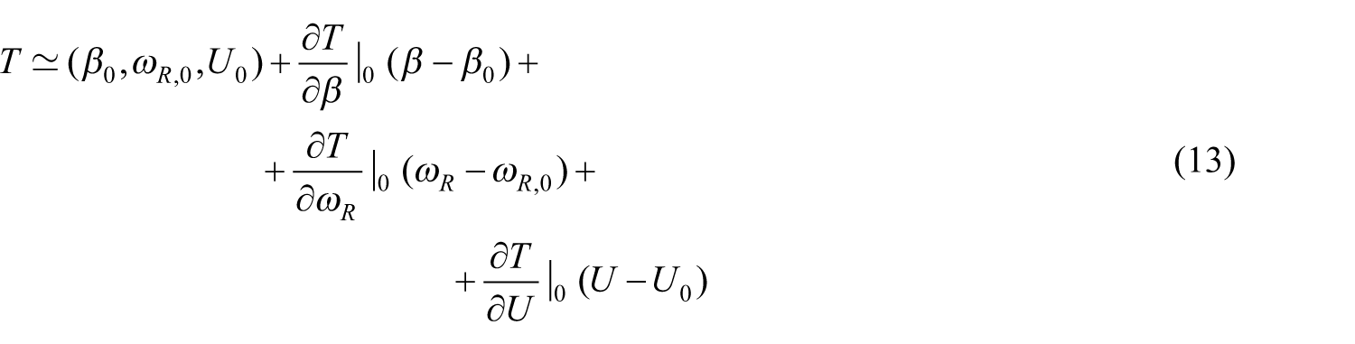
Rotor torque and rotor thrust can be written as a function of non-dimensional coefficients as


where
where
Equations (12) and (13) may be written in a more compact form as


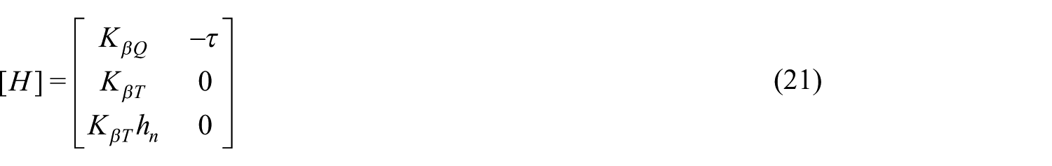
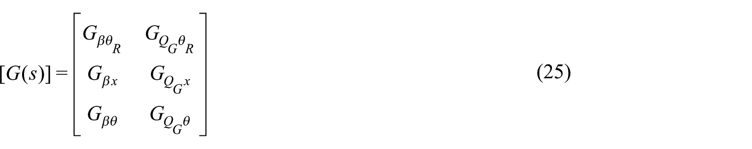
where

By substituting equation (16) into equations (14) and (15)


From equations (17) and (18), it is evident how the unsteady part of the aerodynamic forces depends on the rotor-collective pitch angle, the main control input in the above-rated region, and the system states taken into account by the reduced-order model. In particular, any term depending on the system states acts on the floating wind turbine as an equivalent damping and may be moved on the left-hand side of equation (8) that becomes

The overall FOWT damping is given by the superposition of the constant equivalent hydrodynamic damping matrix

By looking at the equivalent aerodynamic damping matrix, reported in equation (20), it becomes evident how the aerodynamic forcefield is responsible of the coupling between the rotor DOF and the platform DOFs. The aerodynamic coupling is function of the mean wind speed and so of the wind turbine operating point. The input matrix, function of the considered operating point, is
and defines how a variation in the control inputs from their steady-state value
Controlled FOWT response
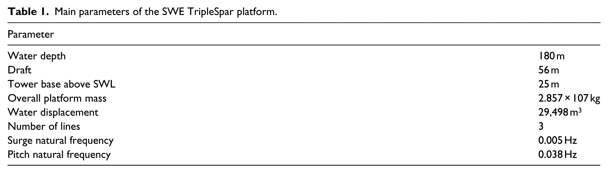
Literature has shown how the interaction between low-frequency platform modes and a pitch control system designed for onshore operations may lead to a low-damped or unstable motion of the floating system. Numerical simulations were performed on the FAST v8 model of the DTU 10 MW (Bak et al., 2013), coupled with the Stuttgart Wind Energy (SWE) TripleSpar floating platform developed by Lemmer et al. (2016a), in order to assess the nonlinear controlled system response and to verify the influence of the power controller on overall stability.
Decay simulations in still water and under a laminar wind field were performed enabling the action of the power controller designed for the onshore version of the RWT. In Figure 2, the FOWT response in terms of rotor speed, platform surge, platform pitch, and rotor-collective pitch angle is shown for two above-rated wind conditions, where the rotor speed is regulated by the pitch controller, while the generator torque is held constant (see Hansen and Henriksen, 2013).
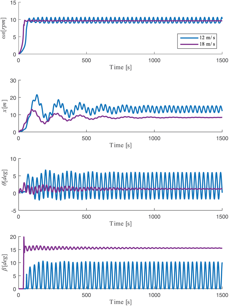
Response of the DTU 10 MW on the SWE TripleSpar platform for above-rated conditions and original pitch controller gains.
When a 12 m/s wind step is applied to the floating wind turbine, this is interested by an unstable response. Platform pitch oscillations are amplified by the pitch controller action and affect the response of the other DOFs, platform surge and rotor azimuth. The same behavior is seen for wind steps up to 17 m/s. When the FOWT undergoes a wind step of 18 m/s or higher, the system response is stable, showing positively damped oscillations.
Linear closed-loop dynamics
The linear model presented in the previous section was used to study the closed-loop dynamics of the DTU 10 MW on top of the SWE TripleSpar platform, so to clarify how the control system action affects the system response at different operating conditions. A Laplace domain representation of the floating wind turbine can be directly obtained from equation (19) as

where

is the equivalent damping matrix due to the hydrodynamic and aerodynamic forcefields at the considered operating point. The analytical transfer function matrix from control inputs

and the three-by-two matrix is
From the analysis of the FOWT transfer function matrix
The transfer function
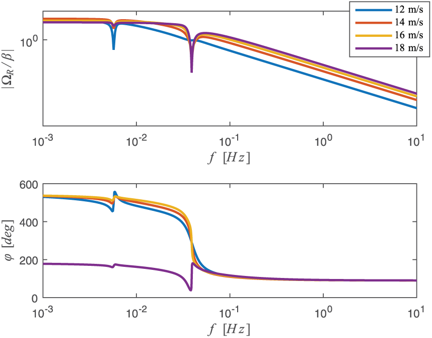
Bode diagram on the FOWT transfer function from rotor-collective pitch angle to rotor speed
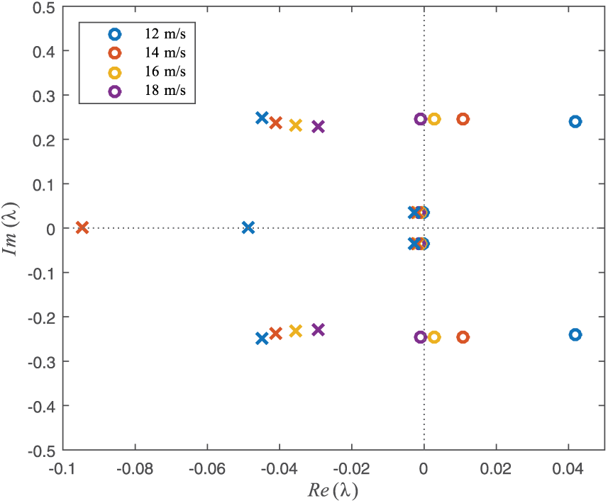
Pole-zero map of the FOWT transfer function from rotor-collective pitch angle to rotor speed
The transfer function shows four complex conjugate poles, corresponding to the platform rigid-body motion-modes, a real pole, associated with the drivetrain mode, and four complex conjugate zeros at frequencies close to those of the platform modes. The surge poles and the corresponding zeros are always close to the imaginary axis at a frequency around 0.005 Hz (see Table 1) and are almost constant for different operating points. The same is not true for pitch poles (the SWE TripleSpar pitch mode natural frequency is 0.038 Hz in still air, see Table 1) and zeros that move significantly in the complex plane considering different mean wind speeds. In particular, above 11.4 m/s (the DTU 10 MW rated wind speed), the pitch zeros are in the right half-plane (RHPZ) and move toward the imaginary axis, crossing it at 17 m/s. For higher wind speeds, the platform pitch zeros have a negative real part. The single drivetrain pole is always in the left half-plane and, for increasing wind speeds, moves far from the RHP.
Main parameters of the SWE TripleSpar platform.
In order to study the FOWT closed-loop response and tune the wind turbine pitch controller gains, the plant transfer function
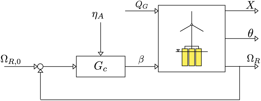
Block diagram of the pitch-controlled offshore DTU 10 MW.
The rotor-collective pitch angle set-point
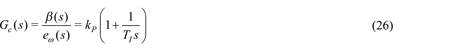
where

The aerodynamic gain scheduling
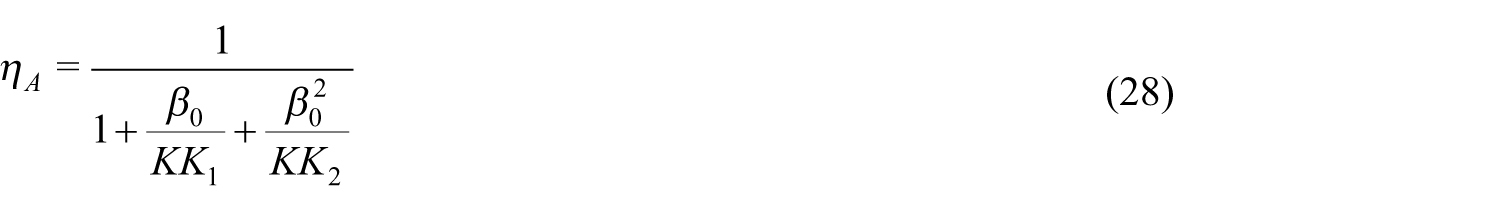
where
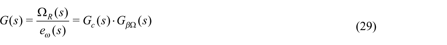
The open-loop transfer function
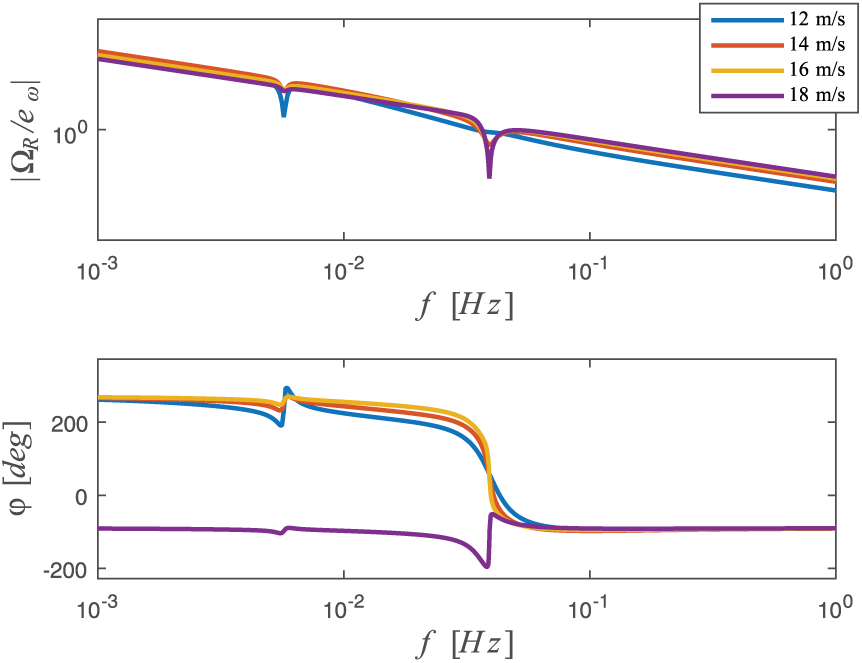
The Bode diagram of
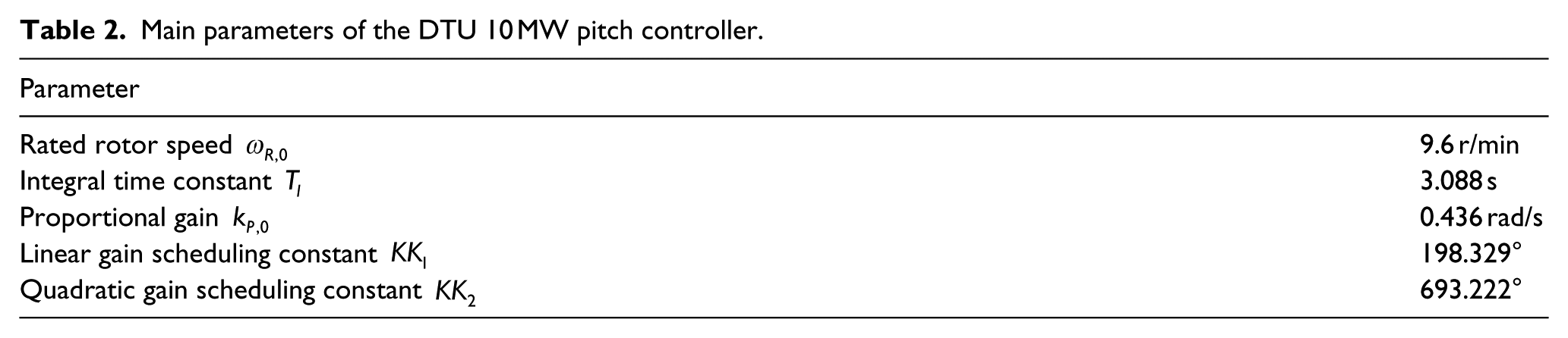
Main parameters of the DTU 10 MW pitch controller.
Bode diagram of the open-loop pitch-controlled drivetrain
The root locus of the pitch-controlled drivetrain is shown in Figure 7 for wind speeds considered in the rest of the analysis. At any operating point, distinguished by a different line color, if the proportional gain
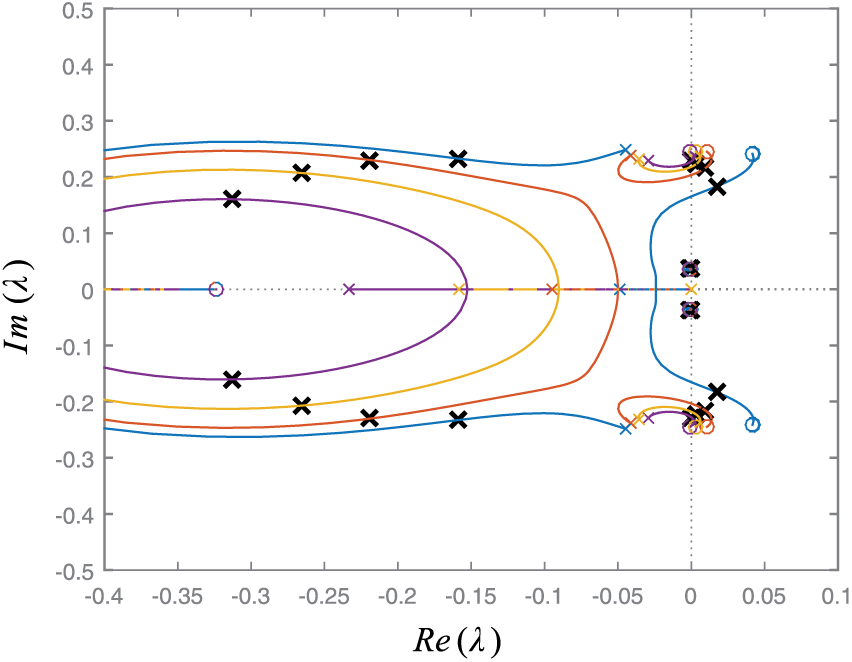
Root locus of the pitch-controlled drivetrain for onshore gains of Table 2. Colored
Onshore controller detuning
The typical approach adopted in literature to solve the pitch controller instability problem is to reduce the controller gains (see, for example, Larsen and Hanson, 2007) limiting the bandwidth to a fraction of the frequency of the platform mode recognized as the most critical for the FOWT response. A reduction of the pitch controller gains results in a lower coupling between the drivetrain and platform dynamics, causing the FOWT to respond more as an open-loop system (Jonkman, 2007). Accordingly, it was decided to tune the DTU 10 WM pitch controller gains, studying the characteristics of the poles of the closed-loop transfer function

In particular, the target of the analysis was to find a combination of gains which maximize the platform damping given and a drivetrain damping around 70%. The damping ratio
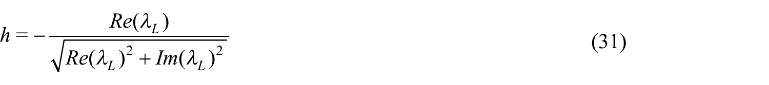
where
Damping ratio of platform pitch mode
Detuned system dynamics
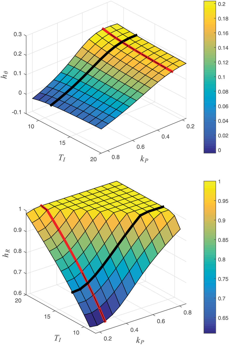
The closed-loop FOWT response with detuned pitch controller gains is assessed from the root locus of the open-loop pitch-controlled drivetrain transfer function
Root locus of the pitch-controlled drivetrain for detuned gains. Colored
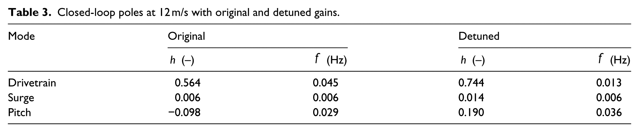
The dynamic characteristics of closed-loop poles at a wind speed of 12 m/s with original and detuned gains are compared in Table 3.
Closed-loop poles at 12 m/s with original and detuned gains.
Numerical simulations were performed on the fully nonlinear FAST v8 model of the floating DTU 10 MW in order to assess the effectiveness of the procedure used to design the turbine pitch controller. In Figure 10, the detuned system response resulting from a 12 m/s wind step is compared with the outputs of the corresponding simulation performed with the original pitch controller tuning (see Figure 2). As visible, the new system response is stable, with pitch oscillations damped after few cycles. Almost no rotor speed oscillations are seen, in agreement with the results of linear analysis, being closed-loop drivetrain poles very close to real axis for wind speed above 12 m/s (see root locus of Figure 9 and damping ratios of Table 3).
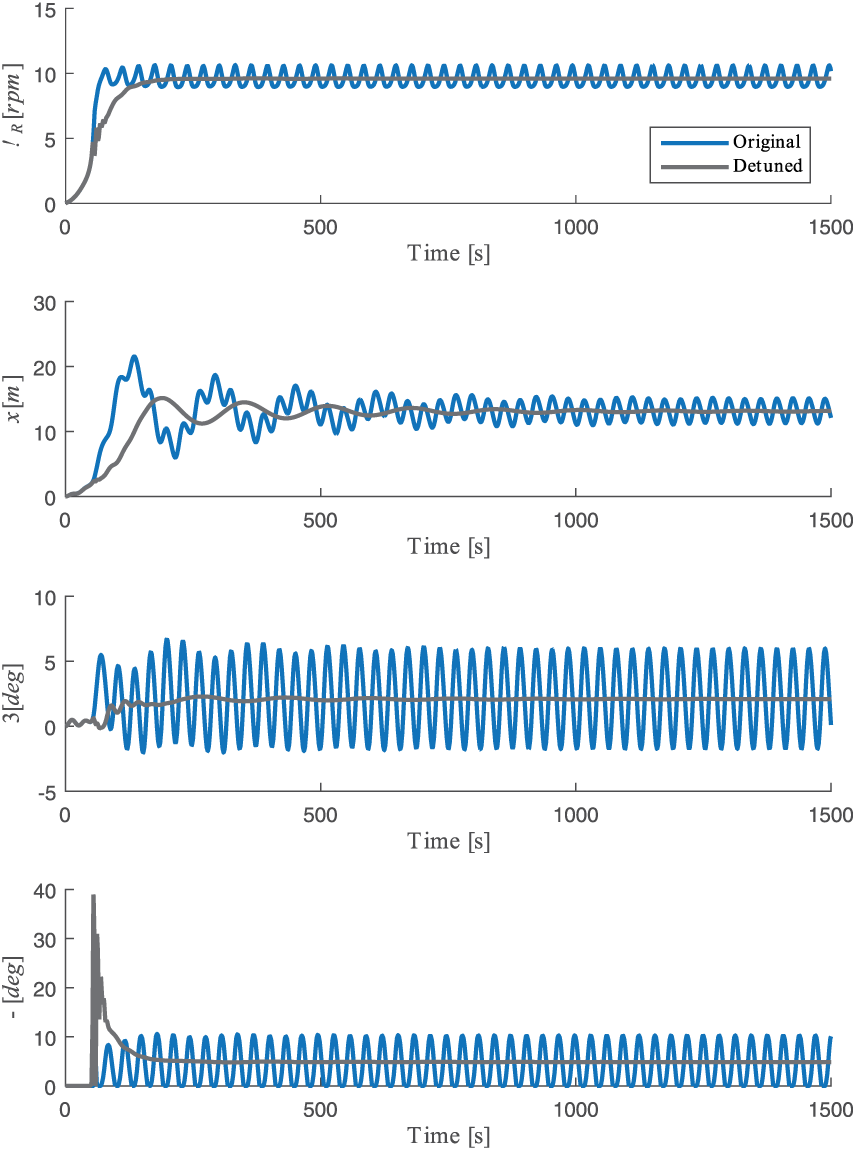
Response of the DTU 10 MW on the SWE TripleSpar platform for a wind speed of 12 m/s (above rated) and detuned pitch controller gains.
Conclusion and future developments
This work presented the analytical formulation of a simple reduced-order linear model useful to describe the dynamics of a generic FOWT. From the model’s coupled matrices, it was possible to directly correlate the platform hydrodynamics to the rotor aerodynamic properties and to extract analytical transfer functions to be used for control design tasks. A systematic procedure for tuning pitch controller gains based on linear analysis was introduced and applied to a floating system composed of the DTU 10 WM RWT and SWE TripleSpar platform. The performance of the detuned pitch controller and the effectiveness of the design procedure were finally assessed through numerical simulations on the fully nonlinear system.
Specific tests were recently performed to characterize the PoliMi wind turbine model aerodynamic performance and the response of the generator and pitch actuators. By introducing experimental data in the linear coupled model presented in this work, it will be possible to clarify the effects of a scaled environment on the FOWT closed-loop response simulated during hybrid HIL tests. A specific tuning procedure will be introduced to work around scaling issues and match the controlled full-scale system response.
Footnotes
Declaration of conflicting interests
The author(s) declared no potential conflicts of interest with respect to the research, authorship, and/or publication of this article.
Funding
This project has partially received funding from the European Union’s Horizon 2020 research and innovation programme under grant agreement No 640741.