
Abstract
Device thrombosis inside ventricular assist devices remains a limitation to their long-term clinical use. Thrombosis potential exists in almost all ventricular assist devices because the device-induced high shear stress and vortices can activate platelets, which then aggregate and adhere to the surfaces inside the ventricular assist device. To decrease the device thrombosis potential of long-term use of ventricular assist devices, a methodology entitled platelet adhesion emulation for predicting the thrombosis potential and thrombosis position inside the ventricular assist devices is developed. The platelet adhesion emulation methodology combines numerical simulations with in vitro experiments by correlating the structure of the flow passage components within the ventricular assist device with the platelet adhesion to estimate the thrombosis potential and location, with the goal of developing ventricular assist devices with optimized antithrombotic performance. Platelet adhesion emulation is aimed at decreasing the device thrombus potential of ventricular assist devices. The platelet adhesion emulation effectiveness is validated by simulating and testing an axial left ventricular assist device. The blood velocity relative to the surfaces of the flow passage components is calculated to estimate the platelet adhesion potential, indicating the probability of thrombus formation on the surfaces. Platelet adhesion emulation experiments conducted in a mock circulation loop with pump prototypes show the distribution of platelet adhesion on the surfaces. This methodology of emulating the device thrombosis distribution indicates the potential for improving the component structure and reducing the device thrombosis of ventricular assist devices.
Keywords
Introduction
In recent years, continuous-flow left ventricular assist devices (LVADs) have been successfully used to rescue severe heart failure patients in many countries.1–6 The most widely implanted LVADs are the HeartMate II, HeartWare HVAD, and HeartMate III. However, adverse events, such as gastrointestinal bleeding, stroke, right heart failure, and thrombosis, have occurred after these VADs were implanted into heart failure patients.7–11 Among these adverse events, pump thrombosis and thromboembolism events exist in most kinds of continuous flow VADs8,12 because the device-induced nonphysiological flow patterns and stresses activate platelets.13,14 The activated platelets aggregate and adhere to the pump surface and form a pump thrombus. It is reported that thrombosis and thromboembolic events can occur in up to 20% of patients with an LVAD. 15 Pump thrombosis may cause pump output reduction and even device malfunction, stroke, and thromboembolic events, which expose patients to the risk of sudden death and can necessitate pump-exchange surgery. Although antithrombotic strategies have been adopted to prevent pump thrombosis, the partial efficacy is limited.16,17 Thus, thrombosis-related events in VADs limit their clinical use.
The progress of thrombosis includes platelet activation, platelet adhesion, and platelet aggregation. Platelets are activated by flow-induced forces, leading to procoagulant substance secretion and thrombin production. Then the platelets adhere to the exogenous surfaces and aggregate. 14 It has been reported that the device-induced nonphysiologically high shear stress in rotary blood pumps is the major mechanical factor for activating platelets and enhancing the aggregation of blood platelets, increasing the potential for pump thrombosis. Therefore, decreasing this potential is an important blood pump design goal.
It is difficult to model the thrombosis process within VADs because of the complexity of the thrombotic process combined with its multi-scale nature; 18 nevertheless, worthwhile research has been conducted to explore the relationship between flow patterns in VADs and pump thrombosis, and a proven effective method for optimizing VAD thromboresistance has been developed. Dumont 19 compared the hemodynamic and thrombogenic performance of two bileaflet mechanical heart valves by computing the platelet damage accumulation along the trajectories. Grigioni 20 proposed an alternative model to describe the blood damage sustained by red cells under unsteady stress conditions. Many in vitro methods have been used to evaluate the thrombogenic potential by measuring the platelet activation state, but these techniques are not sensitive enough for VADs.21,22 Girdhar et al. 23 developed a methodology correlating device hemodynamics with platelet activity by numerical simulation and in vitro measurements to enable device thrombogenicity emulation (DTE) for optimizing the thrombogenic performance of a mechanical circulatory support device. The DTE methodology showed a lower platelet activity rate for the optimized device HeartAssist 5 than for the DeBakey device (Micromed Houston, TX). Wu and Antaki presented a spatiotemporal mathematical model for simulating the three components of thrombus formation, namely, initiation, propagation, and stabilization, and gained an improved understanding of the pump thrombosis in the Thoratec HeartMate II.24,25 Goodman et al. 26 presented a numerical model of thrombosis/thromboembolism that predicts the progression of thrombus growth and thromboembolism in low-shear devices by solving the coupled convection-diffusion-reaction equations to predict velocities, platelet transport, and adhesion to biomaterial surfaces and adherent platelets.
The conventional method of predicting the pump thrombosis potential is numerical simulation. The cost of verifying the simulated pump thrombosis potential and location with a sufficient number of animal experiments or clinical trials is prohibitively high. Therefore, with the aim to optimize VADs with optimized antithrombotic performance, it is necessary to develop a methodology that combines numerical simulations with in vitro experiments to estimate thrombosis potential and location. This study reports a method of emulating platelet adhesion inside VADs with numerical simulation and in vitro particle adhesion experiments. Figure 1 displays a thrombus generated in the bearing/shaft region of the LAP31 prototype in an animal experiment. This method was verified by predicting thrombus deposition that has been observed in animal experiments in continuous-flow LAP31 VADs. This emulation of the device thrombosis distribution indicates the potential of the method for improving the component structure and reducing the device thrombosis of VADs.
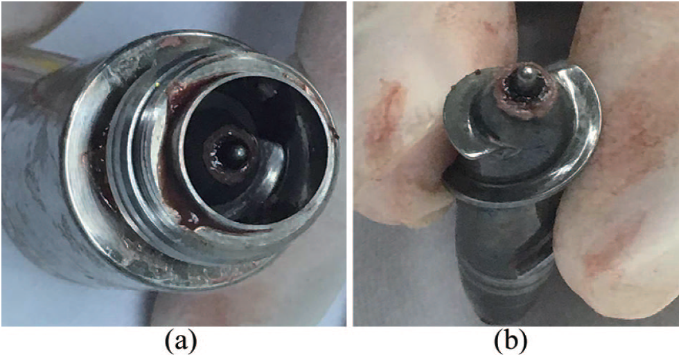
Thrombus generated inside the LAP31 prototype: (a) before disassembly and (b) after disassembly.
Materials and methods
Platelet adhesion emulation experiment
The structure of the LAP31 test blood pump is illustrated in Figure 2(a). The flow components of the LAP31 are composed mainly of three parts: three inlet guide vanes (IGVs), two rotor blades, and six stator blades. The casing of the LAP31 test pump consists of transparent polymethyl methacrylate.
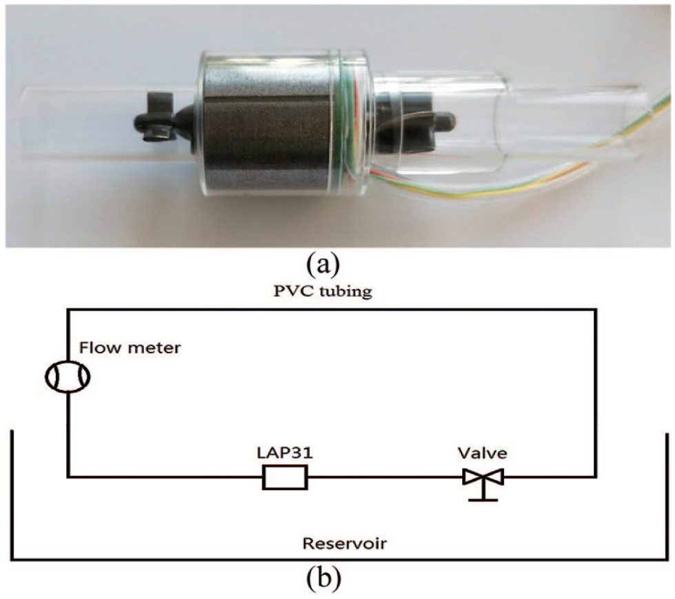
(a) Structure of the LAP31 test pump and (b) scheme of the test loop.
We conducted a particle adhesion and deposition experiment to simulate platelet adhesion on the blood flow surfaces inside the LAP31 axial blood pump. The simple loop consisted of an acrylic reservoir, a flow meter, a flow valve, PVC tubing, and the transparent LAP31, shown as Figure 2(b). The loop was filled with water, glycerin, and fluorescent particles. The dynamic viscosity of the 40% orange red glycerol solution was 3.5 × 10³ Pa s to match the blood viscosity. The diameter of the magnesium arsenate fluorescent particles was 3–5 µm to match the platelet diameter. The density of the fluorescent particles was 1.34 g/cm3. The test axial blood pump was performed at a 3-L/min flow rate and a rotational speed of 9000 ± 50 r/min. The particle adhesion and deposition distribution was observed every hour until the obvious adhesion phenomenon appeared inside the VAD. Then the blood pump was disassembled and photographed.
Computational fluid dynamics simulation model
The flow fields of the LAP31 were analyzed numerically via two-phase continuous flow of solid particles suspended in blood fluid. 13 A highly refined assembly of 16.02 million hexahedral mesh elements without negative cells was generated with a commercial CFD package (Turbo Grid, ANSYS WORKBENCH 17.1, Inc., Canonsburg, PA, USA) for calculation. The boundary layers near the blade zones were meshed with refined O grids to obtain the properties of the boundary layers. More than 90% of the nodes’ skew angles ranged from 16° to 90°. The k–ω model was selected to solve the Reynolds-averaged Navier–Stokes equations describing the LAP31 flow. The convergence cutoff was 1 × 10⁶ and the transient rotor–stator interface was applied. The time step was adjusted to 5.55 × 10⁵ s with respect to the rotational speed to yield a 3° rotation per step.
The CFX solver (ANSYS WORKBENCH 17.1, Inc.; Canonsburg, PA, USA) was used for the simulations. The rotational speed of the impeller of the LAP31 was specified as 9000 r/min. The incompressible blood was modeled as a Newtonian fluid with a density ρ of 1055 kg/m3 and a dynamic viscosity of 3.5 × 10³ Pa s. 27 In order to track the flow, approximately 30,000 platelets that were assumed to be spherical solid particles with a density of 998.2 kg/m3 were seeded on the upstream plane of the LAP31. 28 A mass flow of 3 L/min was applied in the outlet region, and a pressure of 10 mmHg was applied in the inlet region.
Results
Particle adhesion and deposition
The blood pump rotated 2 days and then obvious adhesion phenomenon was observed inside the blood pump. The fluorescent particle adhesion and deposition process emulating the activated platelet deposition inside the blood pump are presented in Figure 3. The fluorescent particles are red. The encircled regions are the adhesion and deposition regions. The particles deposited on the bearing region of the IGV, as shown in Figure 3(a). There are three deposition regions on the rotor impeller: on the shaft–hub interface, on the blade tip surface, and on the rotor hub–outlet guide vane (OGV) blade root interface, as shown in Figure 3(b) and (d). The particles also deposited on the bearing region of the OGV, as shown in Figure 3(c). The most severe deposition exists on the bearing concave end surface, as shown in Figure 3(a)–(c). There is no deposition on the hub or blade surfaces of the IGV, rotor impeller, or OGV.
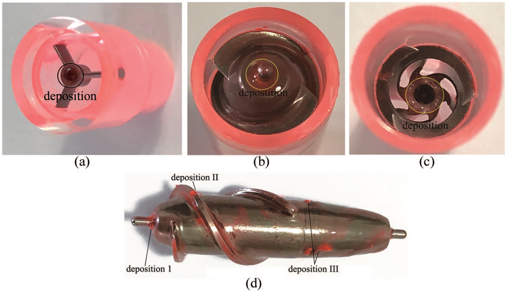
Particle adhesion and deposition inside the blood pump: (a) IGV, (b) rotor inlet, (c): OGV bearing, and (d) rotor surface.
Wall shear stress
The platelet adhesion and deposition potential are numerically estimated based on the wall shear stress (WSS) and local velocity on the rotor impeller surfaces. The simulated WSS on the LAP31 rotor impeller surfaces is presented in Figure 4. The regions of relatively low WSS are the shaft–hub interface, rotor blade root, and OGV flow passage, as shown in Figure 4.
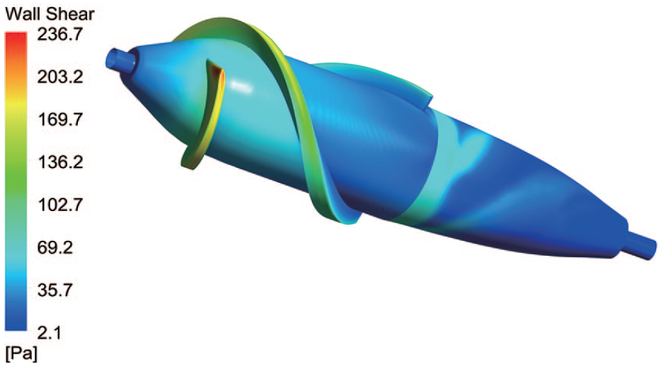
Distribution of the wall shear stress on the rotor surfaces.
Local velocity
The simulated local velocity near the LAP31 rotor impeller surfaces is presented in Figure 5. Regions of relatively low local velocity are located at the shaft–hub interface, rotor blade root, and OGV flow passage, as shown in Figure 5.
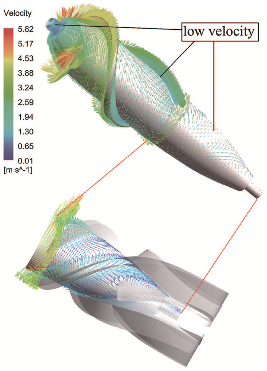
Distribution of the local velocity on the rotor surfaces.
Discussion
The experimental results for fluorescent particle adhesion and deposition show that the particles deposited on the bearing region of the IGV, the shaft–hub interface, the blade tip surface, the rotor hub–OGV blade root interface, and the bearing region of the OGV. Severe deposition appeared on the bearing concave end surface and the path adjacent to the OGV. The deposition on the bearing concave end surface was verified by observed pump thrombosis inside the axial blood pump in animal experiments. For a blood pump, pump thrombosis is most likely generated in the regions of undesirable flow fields, but if or when the pump thrombosis happens is uncertain.
Chiu et al. 28 and Tovar-Lopez et al. 29 proposed that shear stress can “wash” blood-contacting surfaces. The lower WSS is directly related to increased blood platelet adhesion potential. The concave shaft surface is the region of lowest WSS, which explains the phenomenon of a thrombus generated at the shaft surface in the animal experiment. In additional, the local velocity is an important parameter to evaluate the blood platelet deposition for a blood pump. The platelets tend to adhere to the surfaces with lower local velocities. The simulated results show that the shaft surface, the rotor blade root surface, and the OGV flow passage are the regions of relatively low WSS and low local velocity, corresponding to the three regions of severe particle deposition in the particle adhesion experiments. The WSS and local velocity near the OGV blades location are a little higher than that of other region of OGV flow passage. Actually the location of OGV blades changed periodically around the hub of rotor impeller, so both WSS and local velocity in entire OGV flow passage are lower. Both WSS and local velocity in deposition II are higher than those in deposition I and III, but both WSS and local velocity in deposition II are still lower inside the entire VAD. And that these particles perhaps originally deposit on the shroud and are scraped by the blade or the clearance can cause particles deposition even the velocity and shear stress in deposition II are high.
The platelet adhesion and deposition and pump thrombosis potential are generally well predicted by numerical simulation. The process of platelet adhesion and deposition is interrelated with complex biochemical and hemodynamic factors.30,31 Therefore, it is very difficult to synthetically analyze or comprehensively describe platelet adhesion using mathematical models and conventional numerical simulation methods. 24 Aimed at predicting platelet adhesion and optimizing the VAD antithrombotic performance, this simple experimental model can intuitively show the platelet adhesion caused by the pump structure.
This work has limitations. This particle adhesion experiment limits platelet adhesion to an unchanging surface-fluid boundary and does not account for platelet alterations due to biochemical or hemodynamic factors. It also neglects flow-induced platelet activation in the blood pump. This platelet adhesion estimation method can locate potential deposition sites caused by pump components and flow conditions but cannot account for other important mechanisms in the thrombotic process. However, the emulated platelet adhesion agrees very well with numerical simulation and animal experimental observations. Therefore, we believe that this method will provide useful insight into the genesis of platelet adhesion and thrombosis in blood pumps and provide a tool for the design of blood pumps with favorably antithrombogenic performance. In the future, more particle adhesion experiments with more VAD samples should be carried out to verify the effectiveness of this method.
Conclusion
This particle adhesion method is a simple method to emulate the platelet adhesion potential and locate potential platelet adhesion regions in consideration of the pump structure and flow condition. We conclude, based on the particle emulation experiment, activated blood platelets tend to adhere to the bearing region of the IGV, the blade tip surface, the OGV flow passage, and the bearing region of the OGV. The emulated platelet adhesion agrees very well with the numerical simulation results and accurately predicts the occurrence of thrombosis in the bearing/shaft region observed in an animal experiment. Therefore, the platelet adhesion emulation (PAE) method can be applied to analyze and optimize the blood pump antithrombogenic performance.
Footnotes
Declaration of conflicting interests
The author(s) declared no potential conflicts of interest with respect to the research, authorship, and/or publication of this article.
Funding
The author(s) disclosed receipt of the following financial support for the research, authorship, and/or publication of this article: This research was supported by the National Key Research & Development Program of China (2016YFC1300900) and Beijing Science and Technology Plan (Z191100007619053). And Dr Runjie Wei offered support in the experiment.