
Abstract
This article is concerned with the reliable test method for measuring the tensile strength in the longitudinal direction of unidirectional carbon fiber-reinforced plastics. A filament-wound resin-impregnated carbon fiber strand (carbon fiber-reinforced plastics strand) was employed as the specimen. The most important improvement for reliable tests is that the bonding strength of the end tabs with carbon fiber-reinforced plastics strand should be higher than the tensile strength of CFRP strand. We improved the bonding strength by co-curing the carbon fiber-reinforced plastics strand with end tabs. The improved method was applied to two kinds of carbon fiber-reinforced plastics strands and the reliable tensile strengths were obtained.
Introduction
Carbon fiber-reinforced plastics (CFRP), which are lighter, stronger and stiffer than metal, allow integral molding of large members. They have lately been applied especially to primary structure members of aircraft and automobiles that require high reliability under severe service conditions. However, the lack of precise prediction technology for their long-term durability demands the excessive safety factor for structure designing by using CFRP. For that reason, the structure designing to fully exploit the excellent characteristics of CFRP is always prevented.
The mechanical properties of the matrix resin of CFRP, the so-called viscoelastic behavior, vary considerably with time and temperature. Accordingly, the mechanical properties of CFRP using resin as a matrix also vary with time and temperature.1–6 It is necessary to evaluate precisely the time- and temperature-dependent strength of CFRP for the application of CFRP to high-reliable structure to be used for long period under actual temperature environment.
A rectangular specimen is generally used for the tension test measuring the longitudinal tensile strength of unidirectional CFRP, which is the most basic property of CFRP. However, the accurate time- and temperature-dependent tensile strength as well as the static tensile strength at room temperature cannot be measured by this method because of the stress concentration at the grips of specimen and the insufficient strength of adhesive bonding at the grips with tabs. Consequently, it is necessary to establish the reliable longitudinal tension test of unidirectional CFRP for getting the precise tensile properties.
The authors have investigated techniques of precise evaluation of tensile properties of CFRP under a constant temperature environment particularly addressing a resin-impregnated carbon fiber strand (CFRP strand) tensile testing method as a longitudinal tensile testing of unidirectional CFRP.7–9 In this method, CFRP strand is molding by filament winding technique, and then the end tabs are bonded to the CFRP strand (post-bonded CFRP strand). Recently, high-strength carbon fiber strands with numerous filaments have become commercially available. Such strands with a great rupture load present the important shortcoming that a CFRP strand slips in the end tabs before failure. As a result, it can be presumed that the measured tensile strengths were lower and scattered.
In this article, we developed co-cured CFRP strand specimen with end tabs to improve the bonding strength of the end grips with CFRP strand. The performance of co-cured CFRP strand specimen was demonstrated for two kinds of carbon fiber strands.
Evaluation of tensile strength using post-bonded CFRP strand specimen
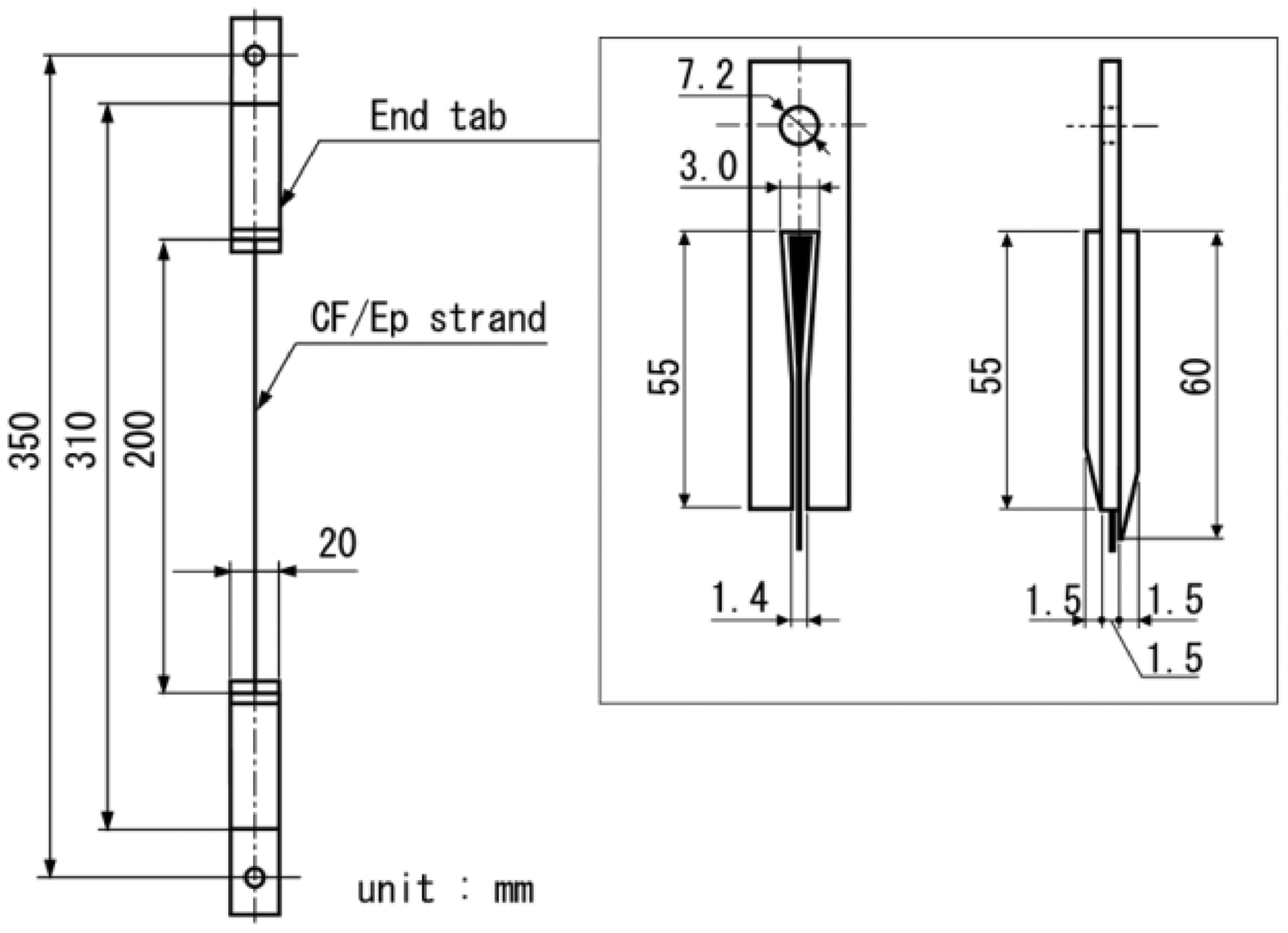
Two kinds of CFRP strands which consist of high-strength type carbon fiber and a general purpose epoxy resin were molded using filament winding machine shown in Figure 1. Two kinds of carbon fiber strands, T300-3000 and T800-12000 (Toray Industries Inc.) were employed. The composition of epoxy resin (Mitsubishi Chemical Corp.) and cure condition of CFRP strand are shown in Table 1. The glass transition temperature Tg of the epoxy resin is approximately 160℃. The fiber volume fraction of CFRP strand is approximately 50%. The diameter and length of CFRP strands are approximately 1 mm and 310 mm, respectively. The end tabs were bonded to the CFRP strand as shown in Figure 2 by using epoxy resin adhesion.
Configuration of winding machine for resin-impregnated carbon fiber strand (CFRP strand). Configuration of post-bonded CFRP strand specimen. Carbon fiber strands and resin system.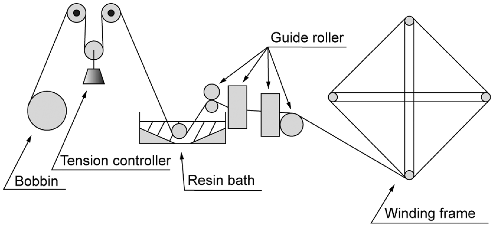
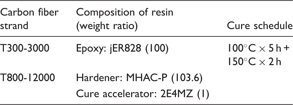
The tensile tests for post-bonded CFRP strand were conducted at room temperature by using the specially designed universal testing machine shown in Figure 3. The cross-head speed was 2 mm/min.
Universal tensile testing machine for CFRP strand specimen.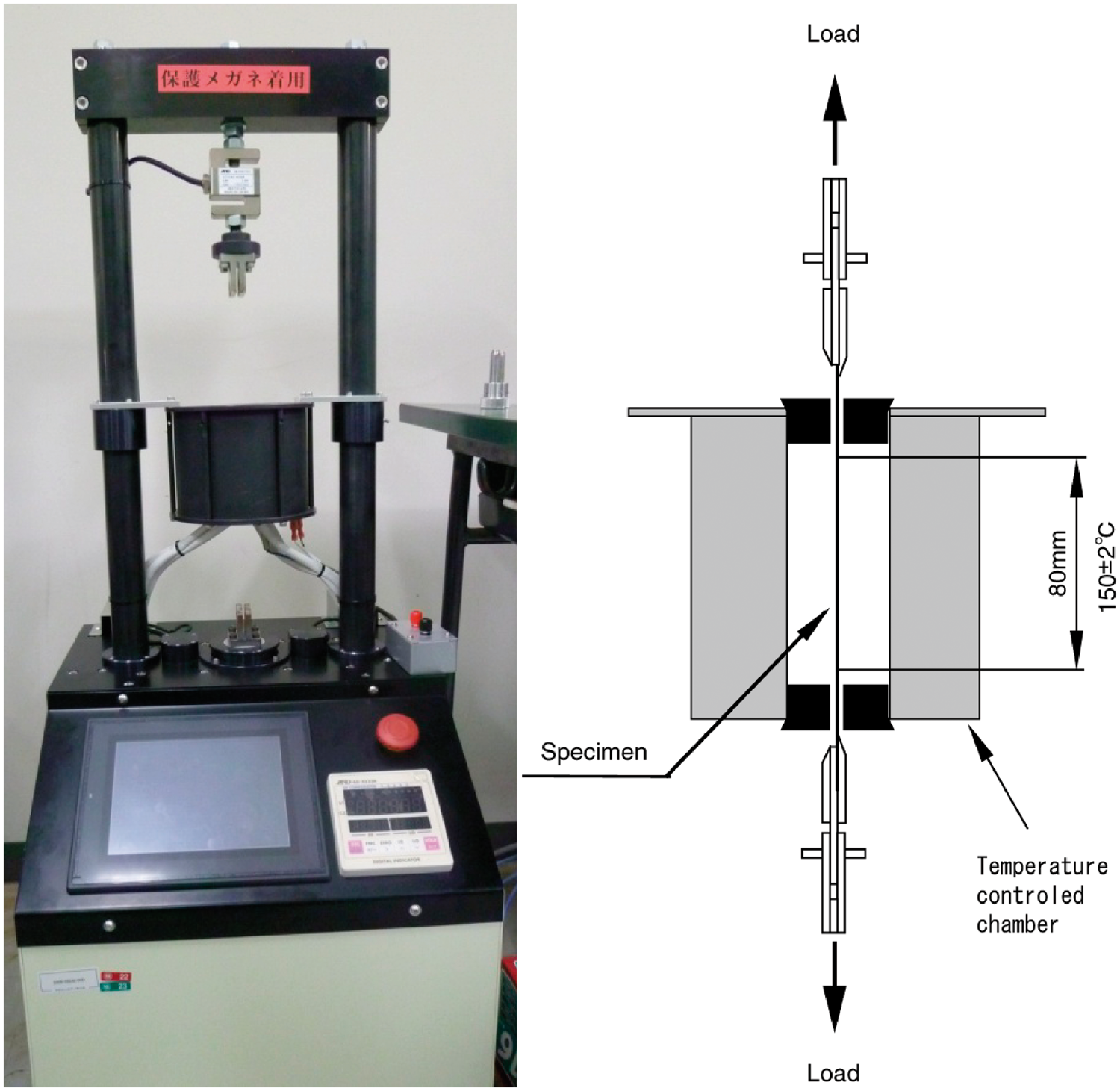
The tensile strength of CFRP strand σs is defined by

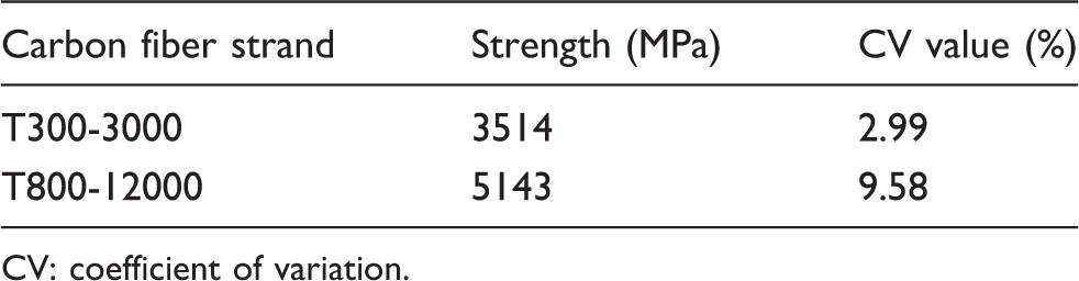
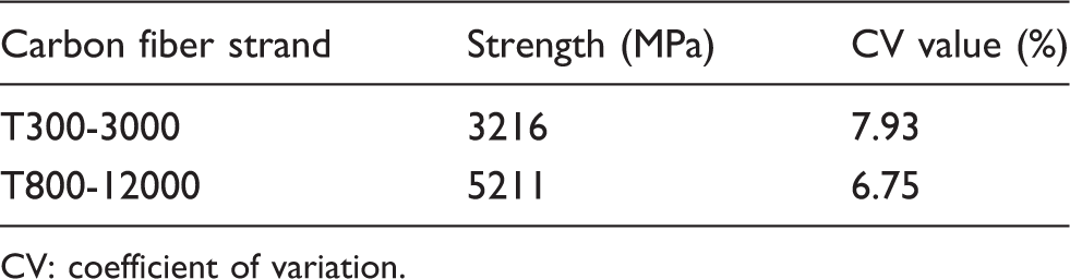
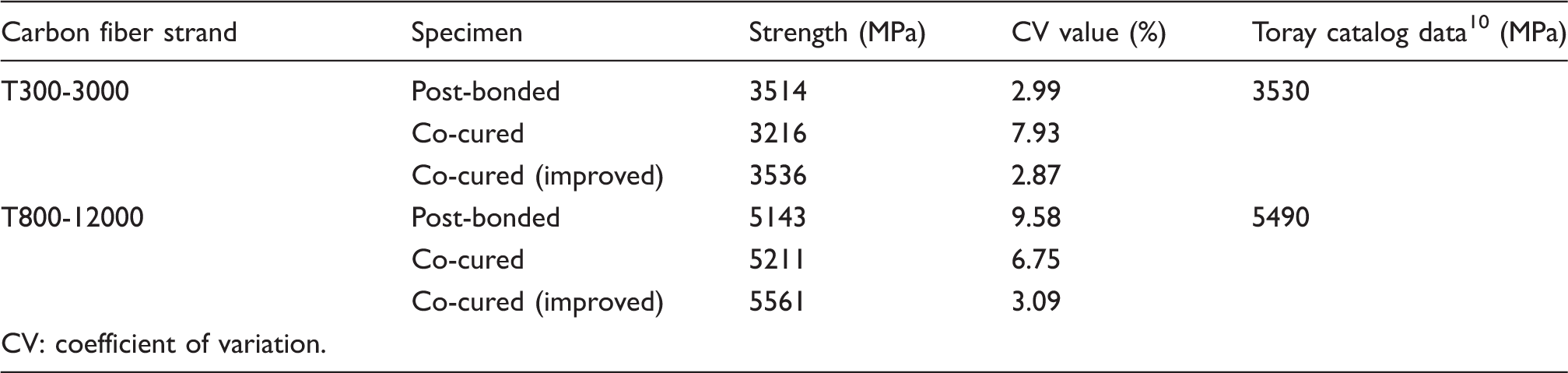
Figure 4 shows the load-elongation diagrams of two kinds of post-bonded CFRP strands. In this figure, the load-elongation diagrams for each specimen are depicted by shifting the origin along the horizontal axis to show all the load-elongation diagrams. The average value and coefficient of variation for tensile strength are shown in Table 2. Stable strength with small variation is obtained for the post-bonded CFRP strand specimen using T300-3000, whereas remarkable slip occurred in the end tabs and the scatter of strength is large for T800-12000.
Load-elongation diagrams for post-bonded CFRP strand specimen: (a) T300-3000 and (b) T800-12000. Static test results for post-bonded specimen. CV: coefficient of variation.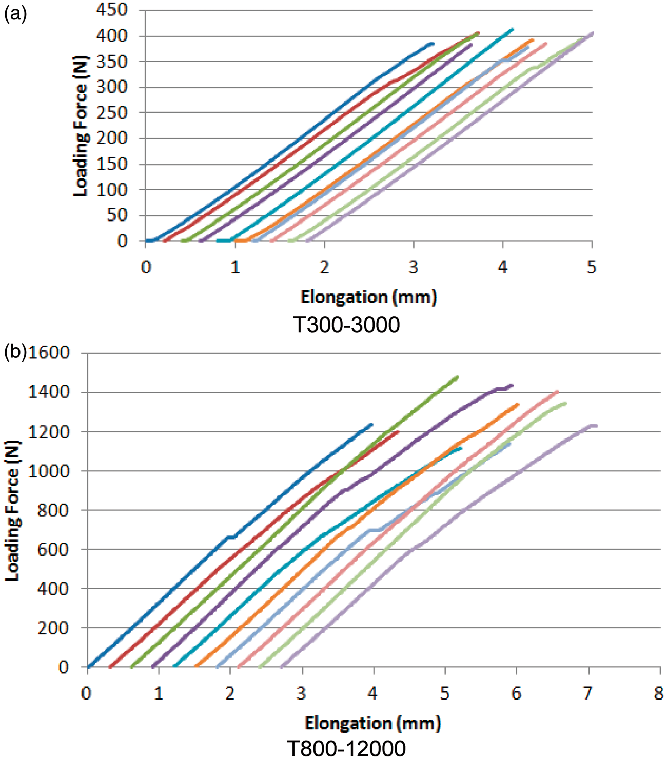
Development of co-cured CFRP strand specimen
Molding of co-cured CFRP strand specimen
The co-cured CFRP strand specimens were molded by using Tabs (1) and (2) as shown in Figure 5. Tabs (1) were mounted onto a winding frame as shown in Figure 6, and resin-impregnated strands were wound around the grooved portion of Tab (1) as portrayed in Figure 7. Then Tabs (2) were mounted as presented in Figure 8, and the winding frame was put into a constant temperature chamber for curing the resin. The co-cured CFRP strand specimens with Tabs (1) and (2) were removed from the winding frame after curing. Tabs (1) and (2) were then fastened with bolts to enhance the bonding strength between the CFRP strand and tabs as shown in Figure 9.
Configuration of co-cured CFRP strand specimen. Winding frame with Tab (1). Hand-winding of strand to winding frame. Assembling Tab (2) to winding frame before curing. Bolt fastening between Tabs (1) and (2) after curing.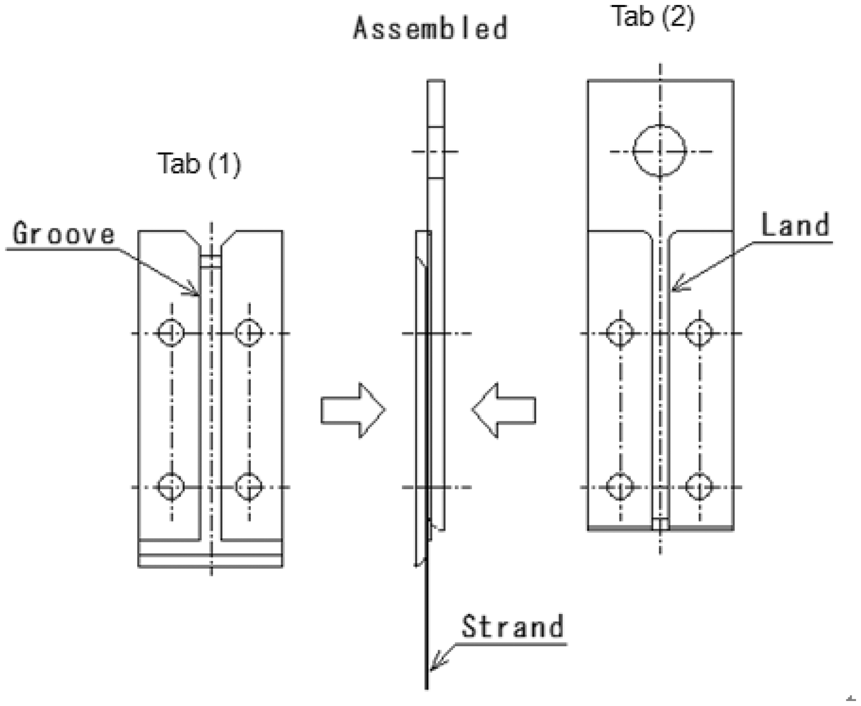

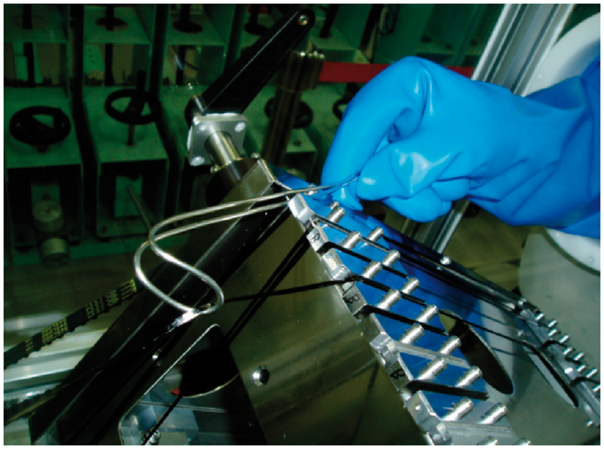
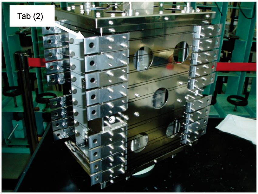
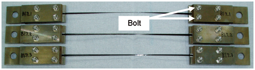
Figure 10 shows the load-elongation diagrams of two kinds of co-cured CFRP strand specimens. The average value and coefficient of variation for tensile strength are shown in Table 3. It was verified that this configuration would prevent slip in the end tabs of T800-12000. However, scatter of strength is still large. For co-cured CFRP strand specimen using T300-3000, the tensile strength is lower and the scatter of tensile strength is large compared with those for post-bonded CFRP strand specimen.
Load-elongation diagrams for co-cured CFRP strand specimen: (a) T300-3000 and (b) T800-12000. Static test results for co-cured specimen. CV: coefficient of variation.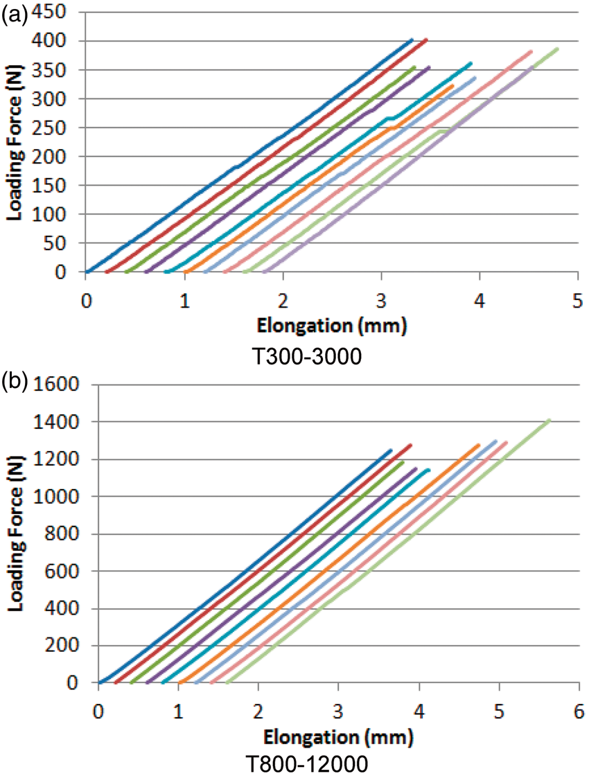
Improvement of co-cured CFRP strand specimen
The causes of strength reduction in the co-cured CFRP strand specimen were investigated and measures were taken. The assumed dominant causes of strength reduction in a co-cured CFRP strand specimen include the damage of carbon fiber during hand-winding shown in Figure 7, stress concentration in the CFRP strand near the end tabs, the damage of carbon fiber by the thermal expansion of winding frame during curing process and the damage of CFRP strand by handling after curing.
We improved co-cured CFRP strand specimen based on the assumptions mentioned above. The causes of damage and measures for preventing the damage are listed in Table 4. To prevent the damage during wining the strand, we modified the winding machine employing traverse as shown in Figure 11(a). By using the traverse, the strand can be wounded to winding frame without hand-winding. To prevent the stress concentration in the CFRP strand near the end tabs, we modified the end tabs having tapers and added the epoxy resin adhesion at the end of tabs as well as in the tapered portions in the tabs as shown in Figure 11(b). To prevent the damage of CFRP strand by thermal expansion of winding frame, we cut strand between specimens before curing as shown in Figure 11(c). To prevent the damage of CFRP strand by handling, we used the holding plates as shown in Figure 11(d). By using the holding plates, the CFRP strand specimen is not bent while removing the CFRP strand specimen from the winding frame.
Improvements on co-cured CFRP strand specimen: (a) without hand-winding of strand by using traverse, (b) add epoxy resin adhesion at the end of tabs, (c) cutting strands between specimens before curing and (d) holding plates for co-cured CFRP strand specimen. Improvement work on co-cured specimen. CFRP: carbon fiber-reinforced plastics.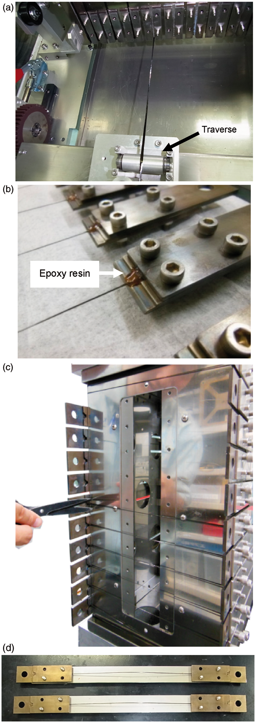
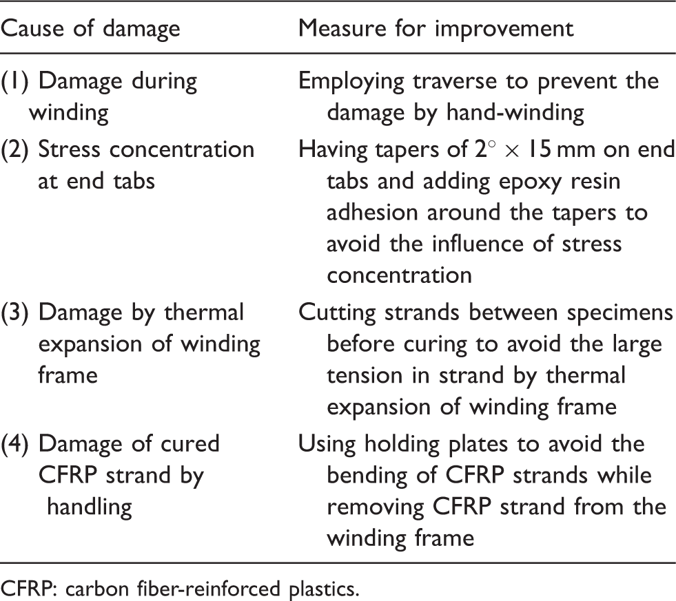
Figure 12 shows the load-elongation diagrams of improved co-cured CFRP strand specimen. The average value and coefficient of variation for tensile strength are shown in Table 5. The catalog data for tensile strength of carbon fiber are also shown in this table. The higher tensile strength compared with the catalog data and the small variation of tensile strength can be obtained by using improved co-cured CFRP strand specimen.
Load-elongation diagrams for improved co-cured CFRP strand specimen: (a) T300-3000 and (b) T800-12000. Static test results for improved co-cured specimen.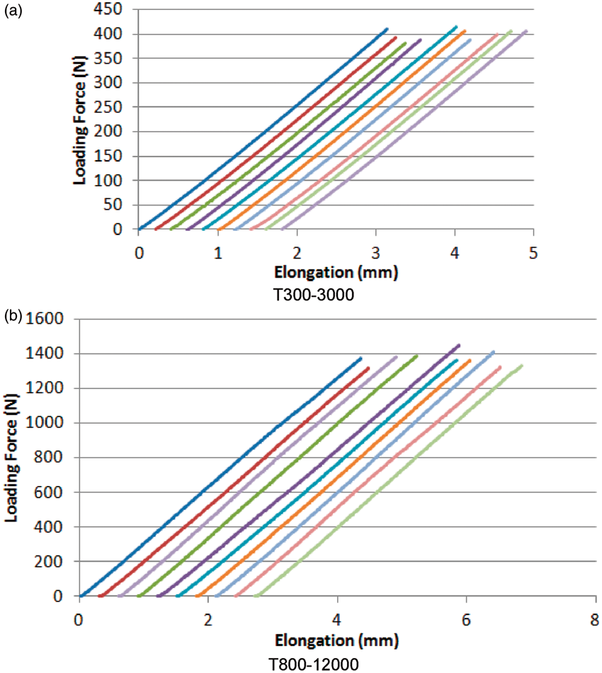
Conclusion
The following improvements were performed for resin-impregnated strand specimen to obtain reliable tensile strength for a CFRP strand with a high rupture load.
A co-cured end tab was adopted as a measure for insufficient bonding strength between resin-impregnated strand specimen and end tabs. Measures were taken for the dominant cause of strength reduction in a specimen with a co-cured tab, so that stable tensile strength was implemented with small variation.
We intend to conduct static strength testing under various temperatures and loading speeds and dynamic strength testing with repeated loading using the improved co-cured CFRP strand specimen, and to promote establishment of a testing method in the longitudinal direction of unidirectional CFRP in the future.
Footnotes
Funding
This research received no specific grant from any funding agency in the public, commercial or not-for-profit sectors.
Conflict of interests
None declared.