
Abstract
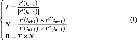
Automated fiber placement shows great potential for fabricating complex aircraft structures. During AFP process, the process-induced defects and placement trajectory have important effect on the processing quality. These defects and trajectory are influenced by many factors, where the attitude of compaction roller is an important factor. By the attitude fine-adjustment of compaction roller, the placement defects and trajectory can be improved. It is necessary to study the effect of the attitude fine-adjustment of compaction roller on placement defects and trajectory. The attitude includes yaw and roll of compaction roller, and the placement defects mainly refer to the fitness degree and fiber pull-up. Firstly, the placement ability of compaction roller is defined by making full use of the allowable distance. Then, the yaw angle and position of compaction roller are calculated by differential geometry. Meanwhile, the yaw distance and placement width are given. Secondly, the fiber pull-up is defined and described as planar sinusoidal based on the fiber waviness theory. Then the roll angle and position of compaction roller are given. Finally, a series of experiments and simulations had been conducted to verify the feasibility of the developed method. Results demonstrate that the method can improve the placement defects and trajectory.
Keywords
Introduction
Advanced composite materials have been used increasingly in some complex aircraft structures such as S-shaped inlet, aircraft fairings, due to their attractive strength-to-weight and stiffness-to-weight ratios. The manufacture technologies of composite material parts involve hand lay-up, filament winding (FW), automated tape laying (ATL), and automated fiber placement (AFP). Traditional hand lay-up is labor intensive, less efficient and involves high level of scrap material. AFP as an extension of FW and ATL has been paid more and more attention with high precision and high efficiency. However, there still exist some known process-induced defects such as gaps, overlaps, wrinkling, disband, and fiber pull-up during AFP process. These defects are usually influenced by processing parameters, mandrel geometric properties, and so on. The attitude of the compaction roller is an important influencing factor which is rarely considered. By fine adjusting the attitude of the compaction roller, the placement defect and trajectory can be improved. Hence, it is necessary to study the effect of the attitude fine-adjustment of compaction roller on automated fiber placement defects and trajectory. This study will contribute to obtain good processing quality and efficiency.
Firstly, the attitude of the compaction roller can improve the placement defect. Currently, some online defect monitoring techniques such as thermographic,1–3 fibre Bragg grating sensors,4,5 machine vision,6,7 simulation software 8 have been proposed. However, we pay more attention to what factors affect the defects at the manufacturing stage and how to improve and decrease the defects. Previously, many researchers had done some works. Qi et al. 9 found that temperature increase, pressure increase, and the lay-up velocity decrease could decrease the tape gap by the experiment. Kim et al. 10 developed a novel fiber placement technique named continuous tow shearing (CTS) using the shear deformation characteristic of dry tow. Then through the prototype tests, it was found that CTS could significantly reduce the fibre wrinkling, resin-rich areas and fiber discontinuity. Based on the CTS technique, Dodwell et al. 11 optimized the buckling and manufacturability by minimizing fiber steering radius. Bottenea et al. 12 presented the influence of feed rate, tow temperature, tow tension, and compaction pressure on gaps and overlaps in the laminate. Results revealed that gaps and overlaps were possible to be minimized or avoided by controlling above manufacturing parameters. Similarly, Arian et al. 13 investigated the effect of design and manufacturing parameters on the gap and overlap area percentages within variable stiffness laminates. It was found that the largest number of tows with the smallest width could yield the minimum gap and overlap area percentages within the laminate. Han et al.14,15 developed the relationship between internal defects and stress wave propagation characteristics during AFP process experimentally. They held that the manufacturing defects could be identified by detecting the characteristics of stress waves. Results showed that the reduction of the peak and the increase of the stability of stress waves could reduce the possibility of the formation of manufacturing defects. However, there are a few studies on the effect of the attitude fine-adjustment of compaction roller on the placement defect. Some scholars had done many researches. Stokes-Griffin et al. 16 studied the influence of roller geometry and roller temperature on thermal contact resistance. Lichtinger et al. 17 analyzed the deformation behavior of the compaction roller numerically and experimentally. Results showed that a non-uniform deformation behavior on flat and curved surfaces had an important effect on gaps, bridging, and steering. Duan et al. 18 studied the pressure uniformity of the compaction rollers with different elasticity modulus. Results revealed that compaction rollers with high elasticity modulus material exhibited good pressure uniformity and reduced the void content. Zhao et al.19,20 investigated the effect of compaction roller on the bonding strength. Results showed the compaction force affects not only the current interface but also affected the interfaces at layers underneath the currently processed layer.
In addition, the attitude of the compaction roller can optimize the placement trajectory. Previously, many researchers paid more attention to other influence factors of placement trajectories. Brampton et al. 21 used a level set method to optimize the continuously varying fiber paths for AFP. The method ensured the continuity of the fiber angles and had greater flexibility in fiber path definition by using the typical Hamilton-Jacobi equation based on sensitivities. Lichtinger et al. 22 investigated the influence of the radiation distribution of the IR lamp on adjacent portions of the tools surface during the complete layup experimentally and numerically. However, abovementioned literature had no direct research on the effect of attitude of the compaction roller on the placement trajectory. Yan et al.23,24 constructed the initial path based on the surface-plane intersection strategy with the determined roller location and orientation. The generated paths had a good performance in that not only were the tows placed on the mold completely but also the tow-number information was included. Chu et al. 25 studied the effect of a roller’s deformation behavior on the laying surface’s placeability by defining an incomplete contact between a laying roller and mold during AFP process. The present study is to analyze the effect of attitude fine-adjustment of the compaction roller on the placement defects and trajectory when the surface geometric properties are given. The attitude of the compaction roller usually includes the yaw, the roll, and the pitching. Here, the roll and yaw of the compaction roller are considered. In addition, the placement defects mainly refer to the fitness degree and fiber pull-up. Then the effect of attitude fine-adjustment of compaction roller on the fiber pull-up and trajectory is analyzed. In the end, some experiments and simulations had been conducted to verify the feasibility of the developed method.
AFP
AFP provides a significant cost reduction in fabricating larger and complex aircraft structures. AFP system has a self-contained fiber placement head with multiple degrees of freedom which is mounted on the robotic end-effector, as shown in Figure 1(a). The placement head is capable of delivering up to 32 narrow tows side by side simultaneously. A stationary or rotational mandrel is used as an inner mold for composite parts to guide the final shape. Then, a band of fibers called a course are fed to the placement head by a series of guide rollers and are deposited on the mandrel course after course under the compaction roller. The compaction roller has high deformation and flexibility and can apply direct contact to make sure that the fibers are bonded to the surface and remove trapped air or spatial gaps, whose motion shown in Figure 1(b). Meanwhile, the incoming prepreg is tacked to the previously deposited material by heating the nip-point region where the fiber/tape and laminate meet.26,27
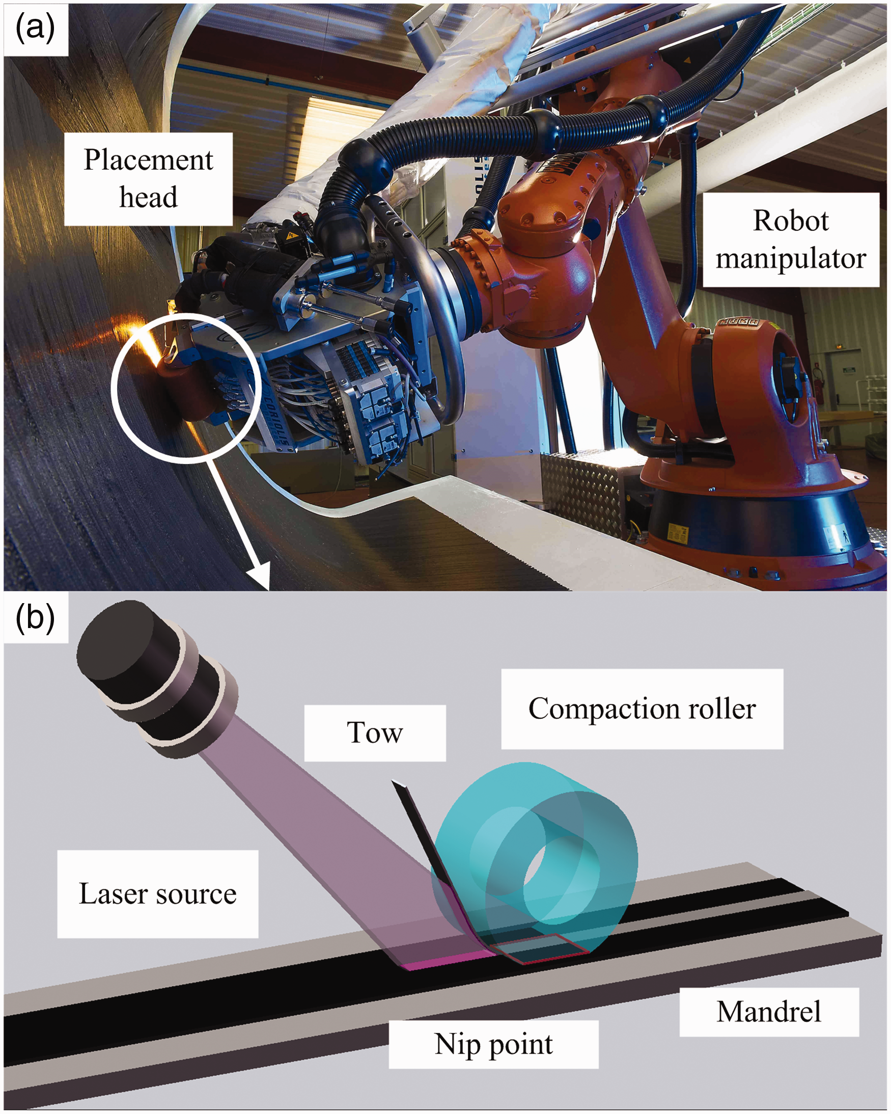
(a). Automated placement equipment. 28 (b) A schematic diagram of the compaction roller motion.
The impact analysis of the compaction roller attitude
There are different types of defects while using AFP (especially during fiber steering) such as tow buckling, wrinkling, and pull up during the fiber placement process. The most primitive result of these defects has two representations: (1) mismatch between the compaction roller and a mold and (2) length discrepancies between the inside and outside edges of a steered tow. At present, there are many methods to resist against the formation of these defects. The adjustment of the roller position and orientations is an important factor. The attitude of the compaction roller usually includes the yaw, the roll, and the pitching. Here the roll and yaw of the compaction roller are considered. How the roller position and orientations can have impact on the defects formation is analyzed based on the above two defect representations. Firstly, the placement criterion is defined by making full use of the allowable distance between the compaction roller and mold. Based on the placement criterion, the yaw angle of the compaction roller is adjusted to improve the fitness between the tow and mold. In addition, the arc lengths on the tow edges can be changed by the roll of the compaction roller. Then some control points are generated that the robot system will aim to follow. Finally, the joint variables are solved by the kinematics equations of the AFP robotic manipulator, and they are input to the controller to adjust the attitude of the compaction roller. The defects are improved by locating the roller in a specific place.
Effect of the yaw of the compaction roller on the placement ability and trajectory
The yaw of the compaction roller is an important attitude and it can improve the placement ability and trajectory. Firstly, the placement ability is defined by making full use of the allowable distance. After that, the placement fitness is improved and the placement trajectory is optimized by differential geometry.
The placement ability of the compaction roller
The placement ability of the compaction roller is defined as how to obtain the maximum fitness degree along the roller axis with an allowable distance. The allowable distance represents the maximal height between the compaction roller and mandrel surface. The definition of the placement ability needs to consider the bending distance of the compaction roller and the fiber deformation at the same time. The placement schematic of the compaction roller is given in Figure 2.In Figure 2, Q is a point in
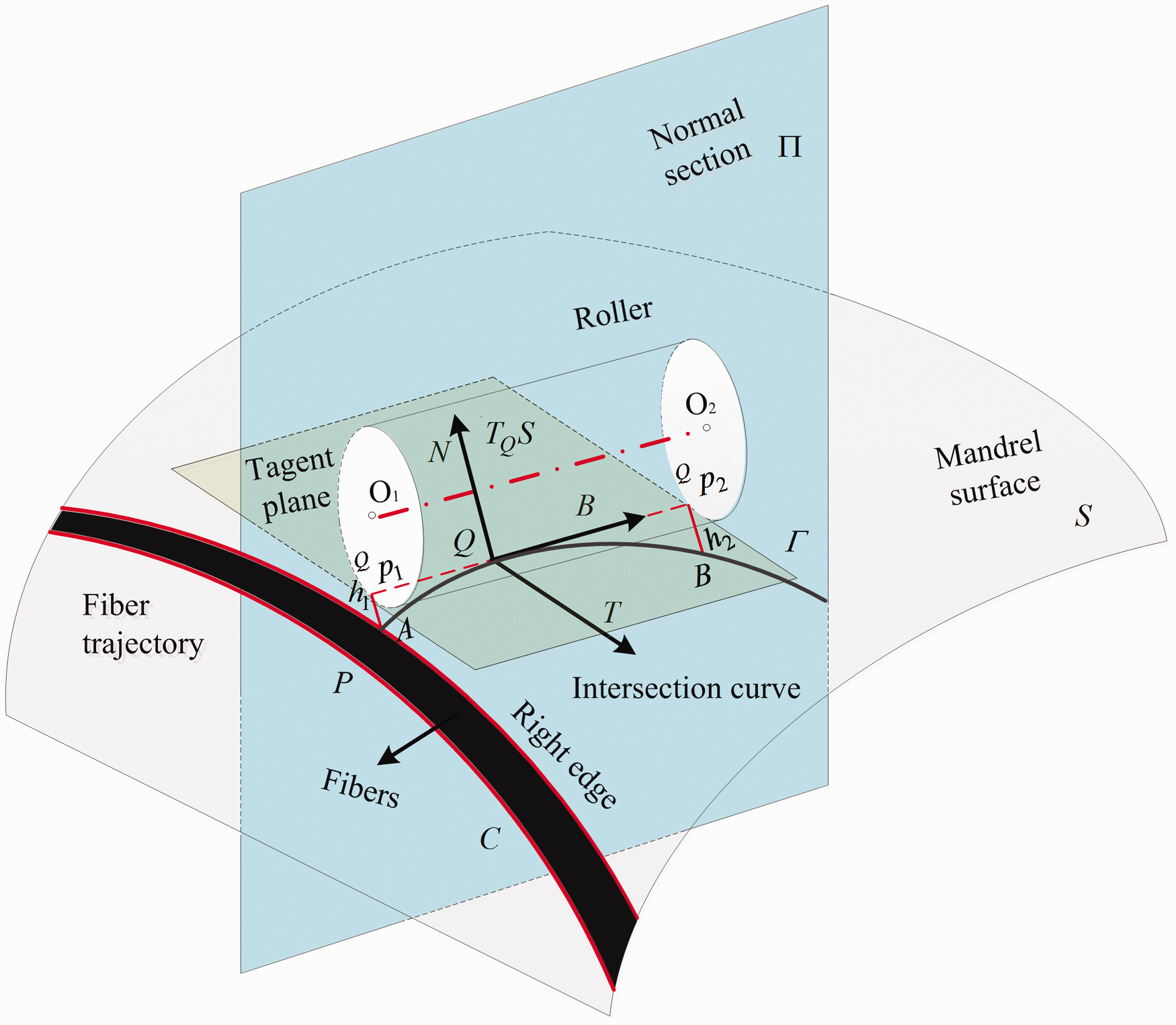
A placement schematic diagram of the compaction roller.
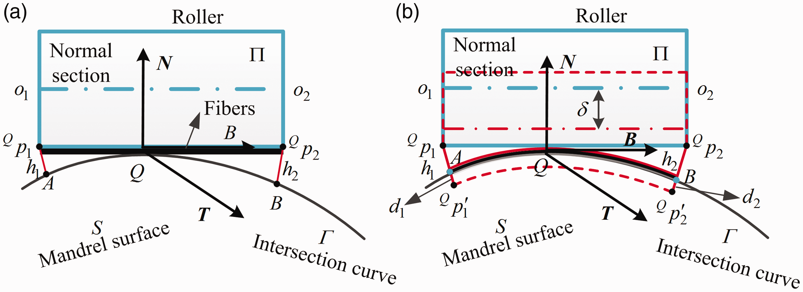
(a) A cross-sectional view of the placement ability before exerting pressure. (b) A cross-sectional view of the placement ability after exerting pressure.
The yaw angle and position of the compaction roller
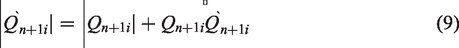
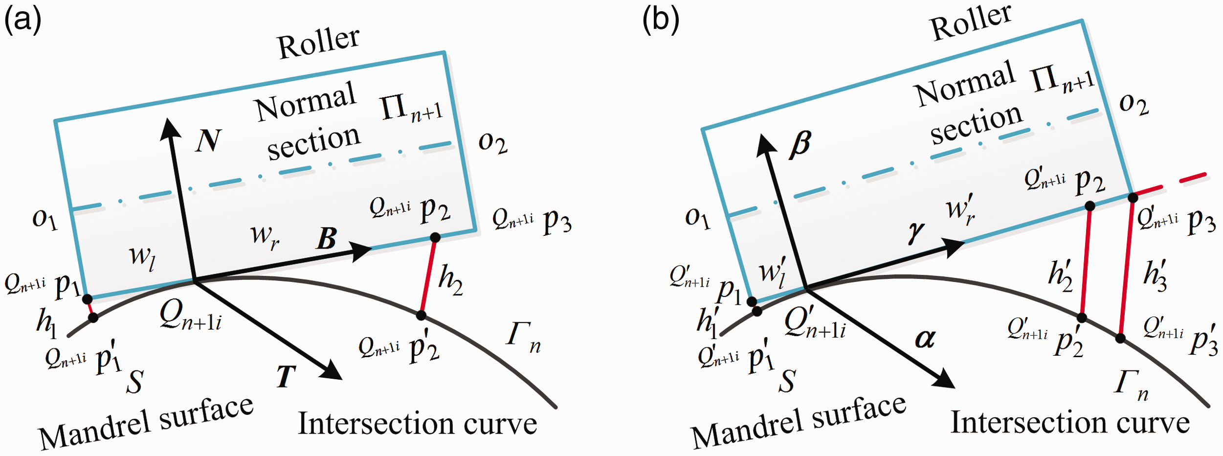
The yaw angle and position can be obtained by the algebraic geometry and differential geometry. The cross-sectional view of the yaw is shown in Figure 4. Assume Qn+1
i
is an arbitrary point at
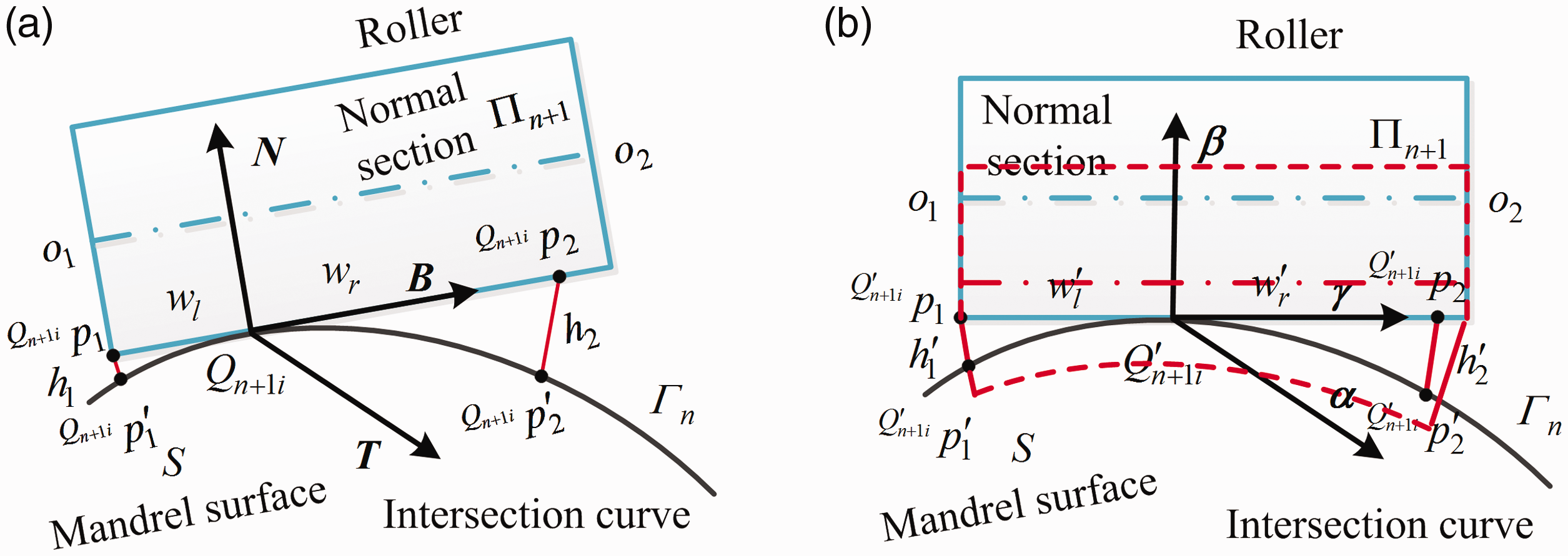
(a) A schematic diagram before the yaw. (b) A schematic diagram after the yaw.
Now a coordinate at point Qn+1
i
is established.

We can obtain the intersection curve
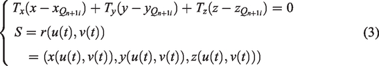
To solve the equations, we assume that u or v is changed with a constant step in its domain. The equations can be solved by Newton iteration method. A number of points on the intersection curve are recorded. By fitting a curve to these points, the intersection curve

Note that, the above intersection curve
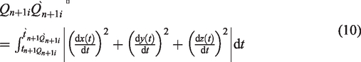
At the moment, the coordinates of the point
Similarly, the length of
If there exists the yaw of the compaction roller, the contact point will be transferred from
Here,
As seen in Figure 4(b),
At last,
The yaw distance and placement width of the compaction roller
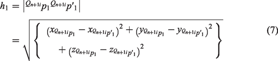
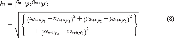
The yaw of the compaction roller makes the contact point shifts from
The several typical situations for the yaw.
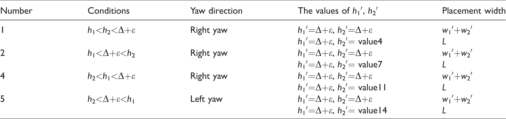
For condition 1, h1 is less than h2 and they are all less than Δ + ε. To improve the placement width and the fitness degree, the compaction roller can yaw from left to right or vice versa. When it yaws towards the left, h1 is reduced to
(a) A schematic diagram before left yaw when h1< h2<Δ + ε. (b) A schematic diagram after left yaw when h1<h2<Δ + ε.
Let
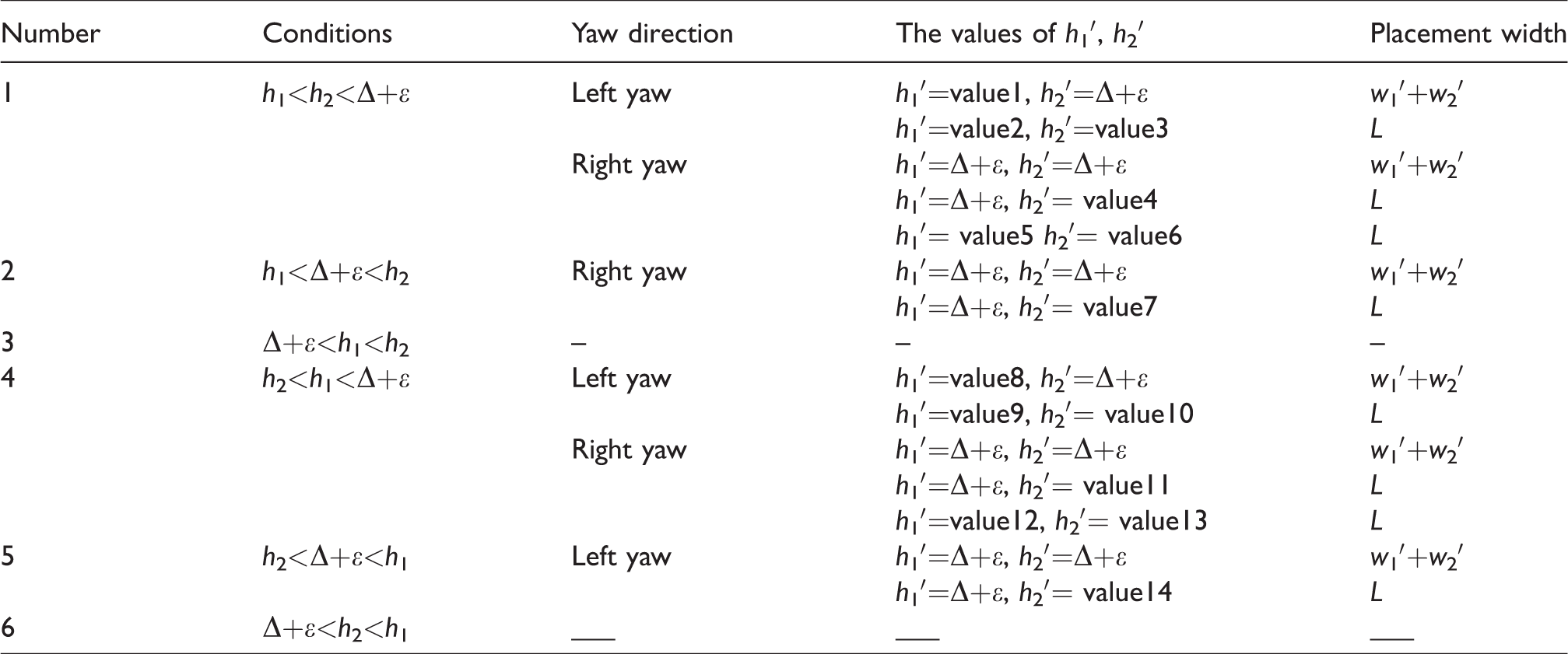
According to the above discussion, one can draw a conclusion as follows. For condition 1, left yaw makes pressure distribution, becomes inhomogeneous and the deformation of the compaction roller becomes larger. Condition 4 corresponds with condition 1; the discussion method is consistent with the above method. Conditions 2 and 5 are a typical case with the focus of our discussion. For conditions 3 and 6, this case is not discussed because it does not accord to the actual project. Finally, the different situations of the yaw can be simplified as follows.
As seen in Table 2,
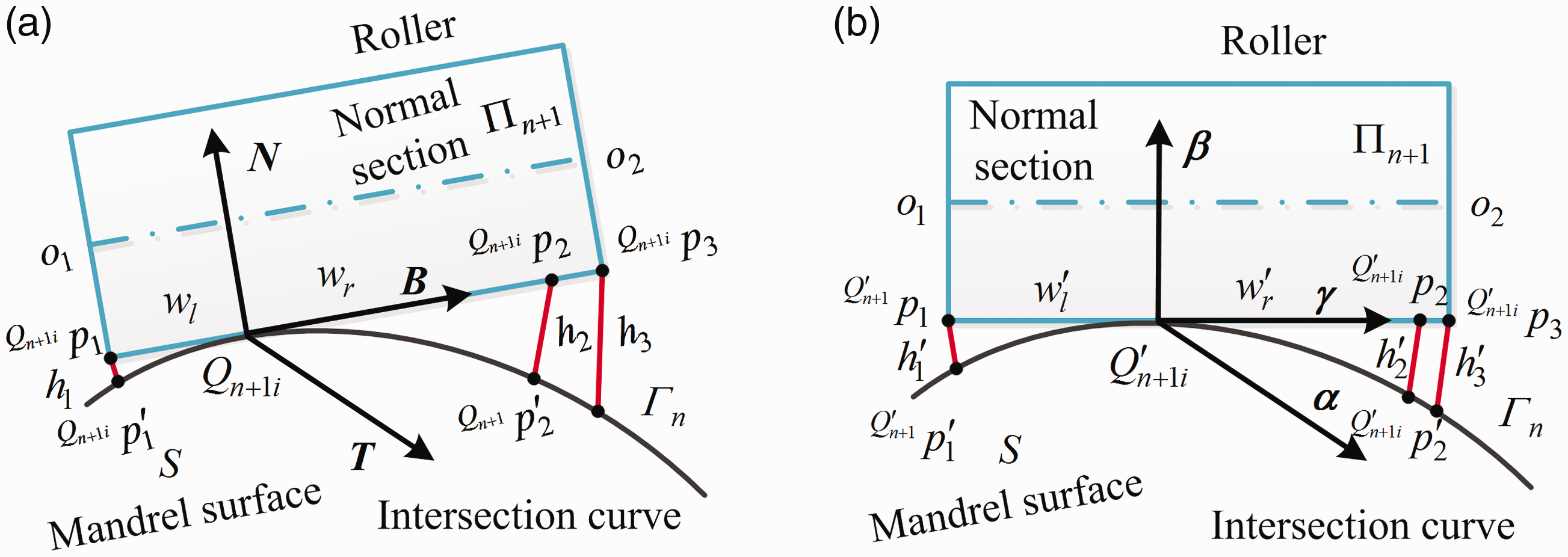
(a) A schematic diagram before the yaw. (b) A schematic diagram after the yaw.
The simplified situations for the yaw.
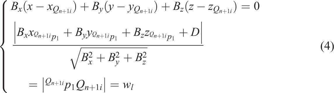
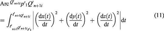
The yaw distance can be determined by the arc length 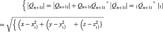
Then, the yaw distance 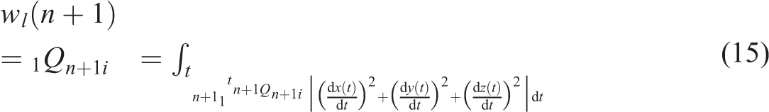
In addition, let 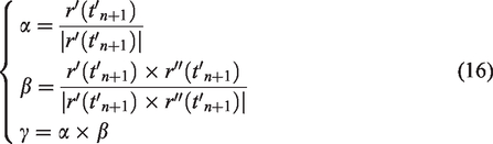
As far as we know, 
Moreover, the coordinate of the point 
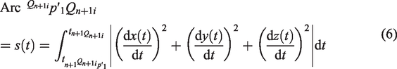
Then, the length of the 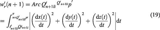
The total placement width is expressed as 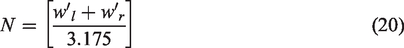
where [ ] are rounded down. The maximum placement width 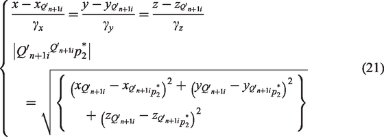
Then the coordinate of the point 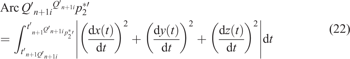
The above discussion is based on the condition that 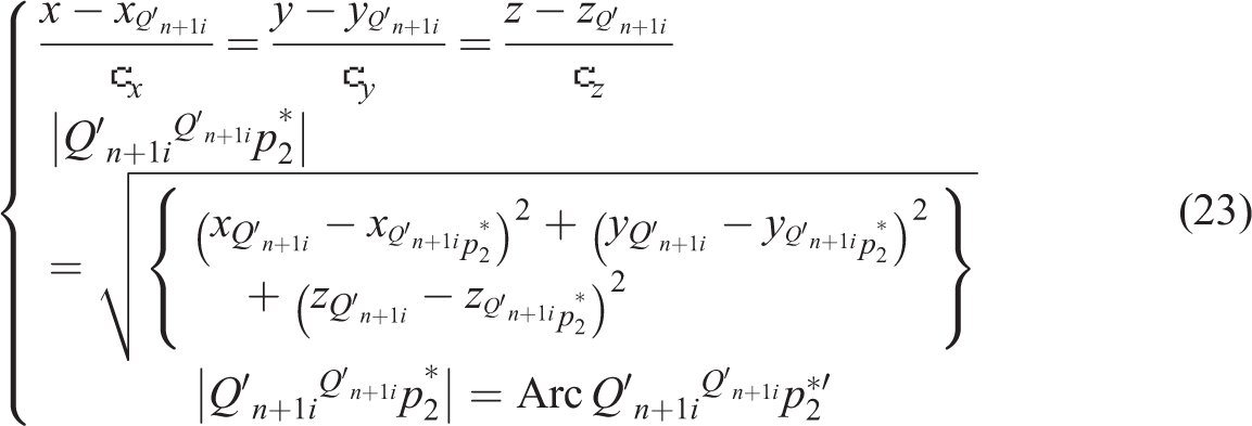
Effect of the roll of the compaction roller on the fiber pull-up
Complex aviation parts such as S-shaped inlet have some points with big curvature. Generally, these points lie at the transition areas. When fibers are deposited on these areas, the fiber pull-up may be produced which affects the final processing quality. The roll of the compaction roller can improve the fiber pull-up by changing the arc lengths on both course edges and the local trajectory is optimized.
The description of the fiber pull-up
The fiber pull-up arises from the inconsistency of the arc lengths on both course edges. It is the result of mismatching fiber length and steering direction. The fiber pull-up is similar to the wrinkling (buckling) and has important influence on composites mechanical performance.29–33 When the fiber is deposited on a curved path, it will result in compressive forces and tensile forces applied through the width of the fiber. If tensile forces are too high, fiber will be lifted beyond the mandrel surface on the outside the steered tow.34,35 The phenomenon is called fiber pull-up. The dimension of the fiber pull-up is different from that of the fiber waviness, which is slightly larger than the fiber waviness. A schematic diagram of fiber pull-up is show in Figure 7.
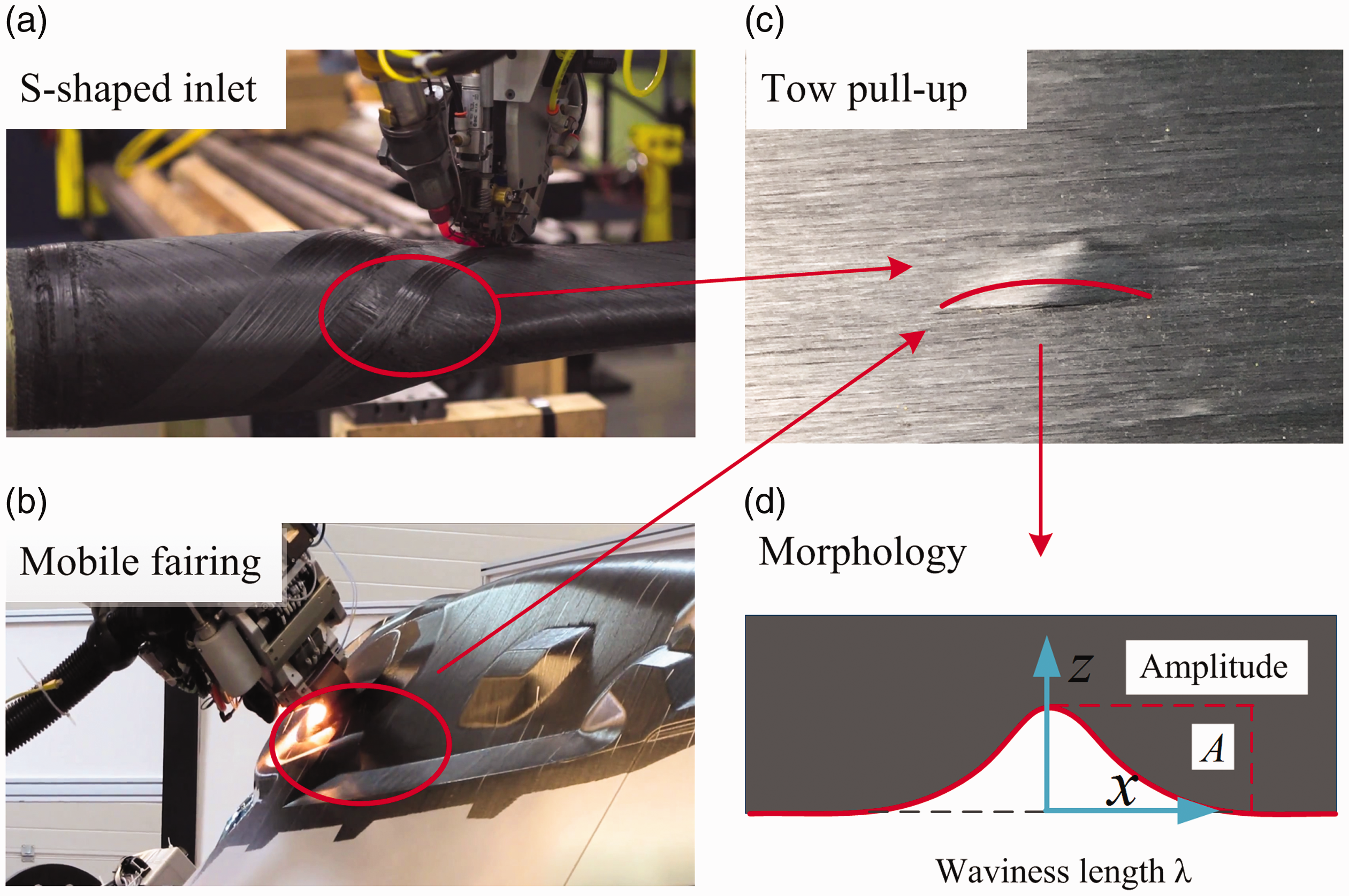
A schematic diagram of the fiber pull-up. (a) S-shaped inlet, (b) mobile fairing (c) tow pull-up and (d) morphology.
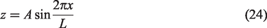
In order to describe the fiber pull-up, it is generally assumed that the fiber pull-up is characterized by a planar sinusoidal according to the fiber waviness theory,36–38 as shown in Figure 7(d).
The roll angle and position of the compaction roller
The roll of the compaction roller can change the arc lengths on both course edges at a fixed point
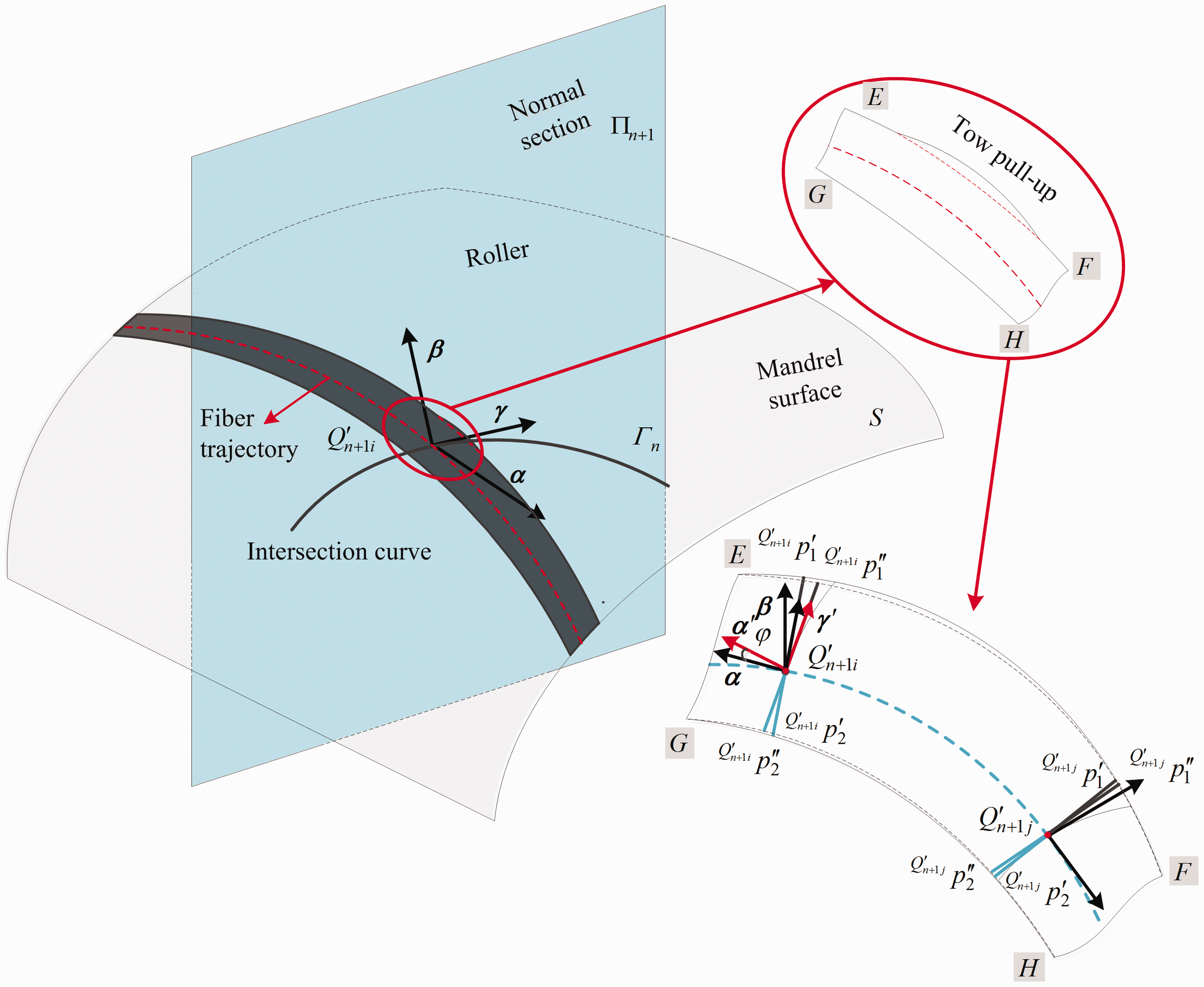
A schematic diagram of the roll for the compaction roller.
As seen in Figure 8, the points E, F, G, H are the points of both course edges corresponding to the original fiber trajectory. The contact point 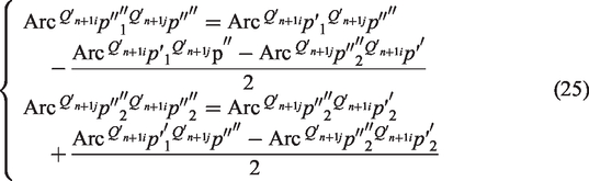

The points 
Then, the three vectors 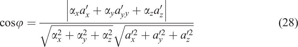
In addition, there has the equation 
We can obtain the intersection curve 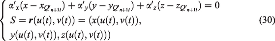
To solve the equations, we still assume that u or v is changed with a constant step in its domain. These equations can be solved by Newton iteration method. A number of points on the intersection curve are recorded. By fitting a curve to these points, the intersection curve 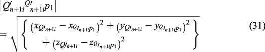
Because the new tangent vector 
Meanwhile, there exists a new fiber trajectory between the point 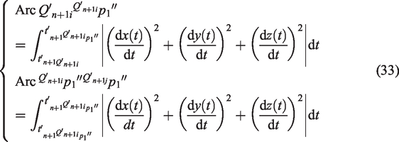
According to equations (29) and (31), the point
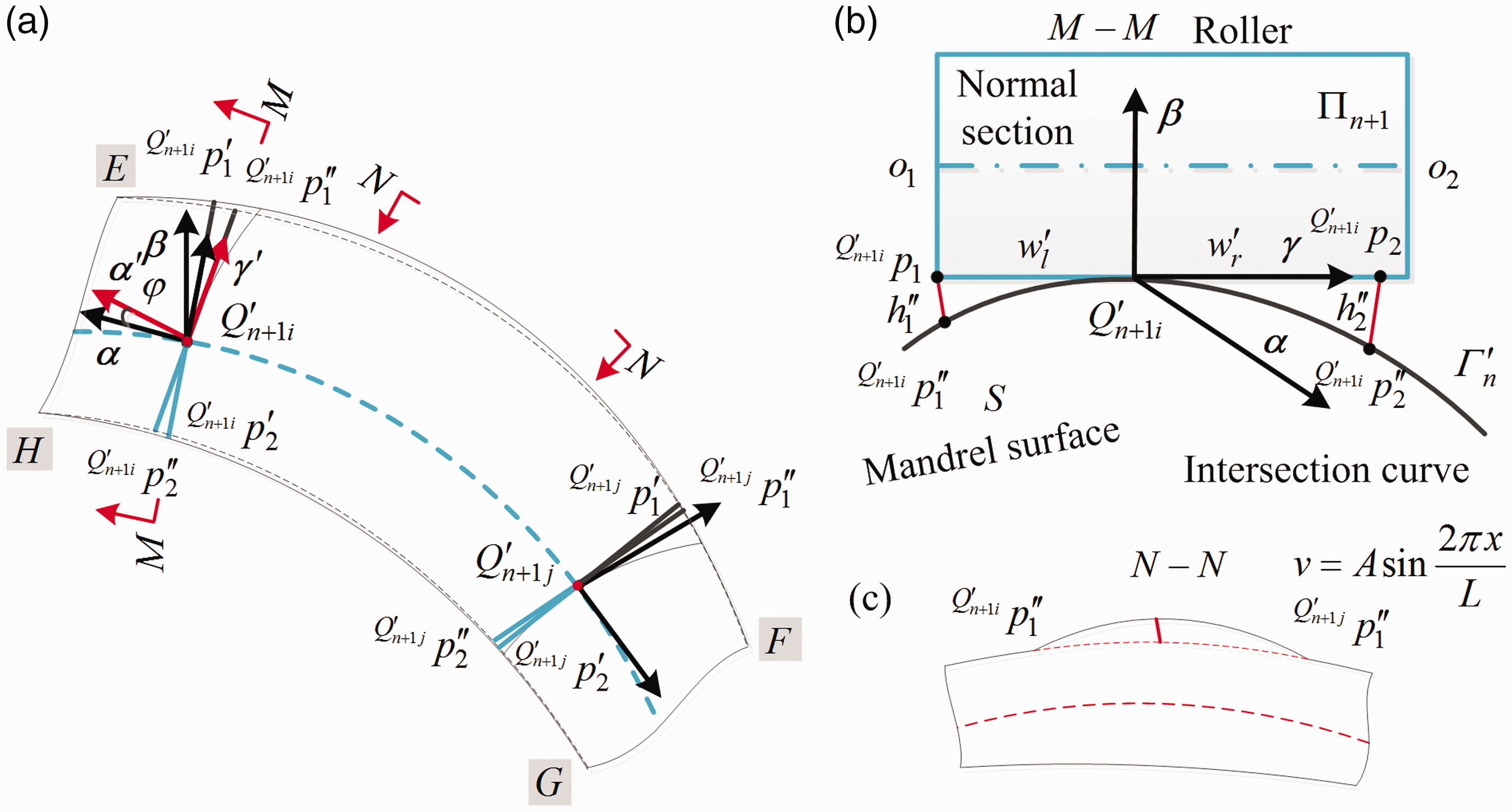
A cross-sectional view of the roll of the compaction roller.
The fiber pull-up is characterized by a planar sinusoidal. It is worth noting that the planar sinusoidal is the outline of the fiber pull-up after the roll. There exist some interpolating points between the point 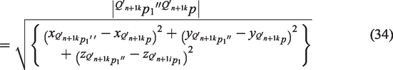
Assume that the maximum value of
Experimental methods
Many experiments had been carried out to analyze the effect of attitude of the compaction roller on the placement defects and trajectory when the surface geometric properties are given. A robotic fiber placement machine developed independently by Nanjing University of Aeronautics and Astronautics was used for this study.
Materials
The thermoplastic prepreg fiber used in this study is T800 epoxy resin carbon fiber prepreg with a width of 3.175 mm and thickness of 0.125 mm, available from Hengshen Co., Ltd, Jiangsu. The fiber volume content is 64%.
The maximum bending distance measurements
The purpose of this experiment was to observe the maximum bending distance of the compaction roller. The deformable roller is widely used as a standard element for AFP. The maximum bending distance of the compaction roller is defined as the maximum geometrical deformation under a given processing pressure. The compaction roller has a shape of a perfect cylinder and is composed of two bearings, a shaft sleeve, and an axis and silicone rubber. The silicone rubber material used in this test is the R-10301 silicone rubber provided by China Bluestar Chengrand Research Institute of Chemical Industry. The compaction force increased from 20 to 100 N and the heat temperature ranged from 20 to 100°C by Bosch hot air generator named GHG630DCE. The line velocity ranged from 1 to 100 mm/s. The tension was controlled by tensioner and kept 4 N. The displacement of compaction roller was obtained by a laser rangefinder LK-G32 produced by Keyence Ltd. 39 In addition, the environmental conditions were kept at ambient temperature of 25 ± 1°C with a relative humidity of 28 ± 3%.
The fiber thickness measurements
The purpose of this experiment was to observe the fiber thickness change of the compaction roller for measuring the fiber deformation in the z direction. The experimental platform mainly consisted of a speed control unit, pressure control system, and temperature controller. Speed control unit could provide a various line velocity ranged from 1 to 25 m/min, and the compaction force ranged from 20 to 100 N. Heat temperature was controlled by Bosch hot air generator with a range of 50 to 100°C. At the same time, the air conditioners and dehumidifiers were available to keep temperature and humidity 25 ± 1°C and 28 ± 3%, respectively. Each layer could be obtained by a peeling machine named UTM6102 provided by Sansi Company. Then, the thickness of each layer was measured by a magnetic thickness gage named Magna-Mike 8600 by OLYMPUS with a range of 0.001 to 25.4 mm. The device was first calibrated and referenced to zero with respect to tool. Data were then stored through RS-232 into the computer for further analysis.
The pull-up waviness measurements
Experiments to detect the fiber pull-up waviness in the specimen were carried out using eddy current testing as shown in Figure 10. A probe was placed above the CFRP specimen, and the pickup coil loop was perpendicular to the fiber direction. A 2 V sinusoidal voltage supplied by Picoscope 5244B was connected two driver coils. The output voltage of the pickup coil was amplified 100 times by a differential amplification circuit, and then measured using an oscilloscope (Pico Technology, Picoscope 5244B, 14 bit, 125 MS/s). The amplitude and phase of the measured voltage were calculated. A Cartesian coordinate system was defined with its origin at the edge of the specimen as shown in Figure 10. The probe was scanned in the x-direction, and data were obtained at 5 mm intervals.
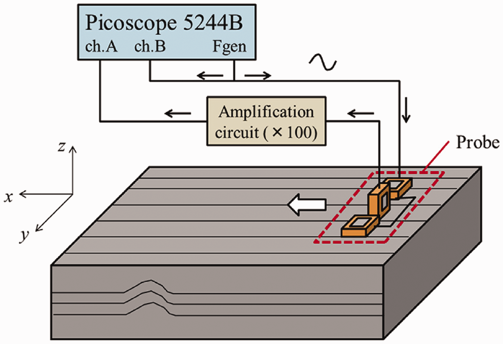
Experimental setup for eddy current testing the fiber pull-up. 40
Results and discussion
To verify the feasibility of the developed method, a simulation and experiment were conducted. In general, most aviation components are free-form and convex mandrel surfaces which are defined as Bézier, B-spline and NURBS surfaces. Here consider a the mandrel surface as Bézier surface to demonstrate the effectiveness of the developed method, whose control points are given by these following points P00(0,0,0), P01(500,0,300), P02(1000,200,200), P10(0,500,100), P11(600,600,100), P12(900,400,0), P20(0,1000,0), P21(400,1000,200), and P22(800,1200,100). The mandrel surface is shown as in Figure 11. The fixed mandrel orientation f of the reference plane is set to be parallel to the x axis. The coordinate of the given point M is (500,600,400), and the projection vector
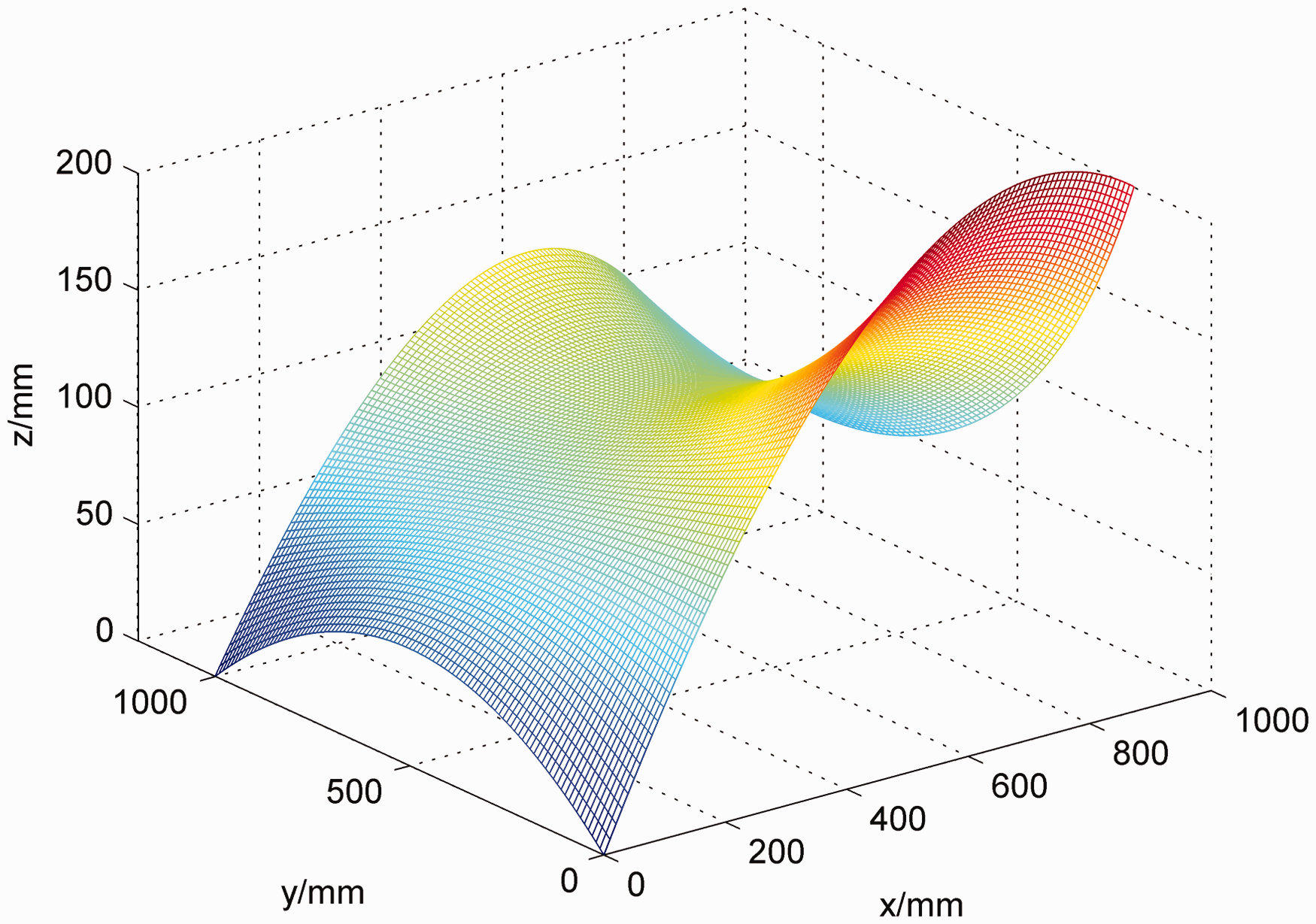
The mandrel surface for simulation.
The abovementioned mandrel surface can be placed with a successive stacking sequence [0°, 45°, −45°, and 90°]. Here we take the 45° layer as an example to verify the feasibility of the developed method. By considering the fine-adjustment of attitude of the compaction roller, a final placement trajectory is given as in Figure 12. Where the heavy line is the reference path, the next path is obtained by perpendicularly offsetting the reference path with the given distance. That is to say, the next path is approximated by interpolating points from the offsetting points. It is found that the placement trajectory can cover the whole surface based on the developed method. Meanwhile, the detailed placement information including the fiber number, yaw angle and roll angle is shown in Table 3.
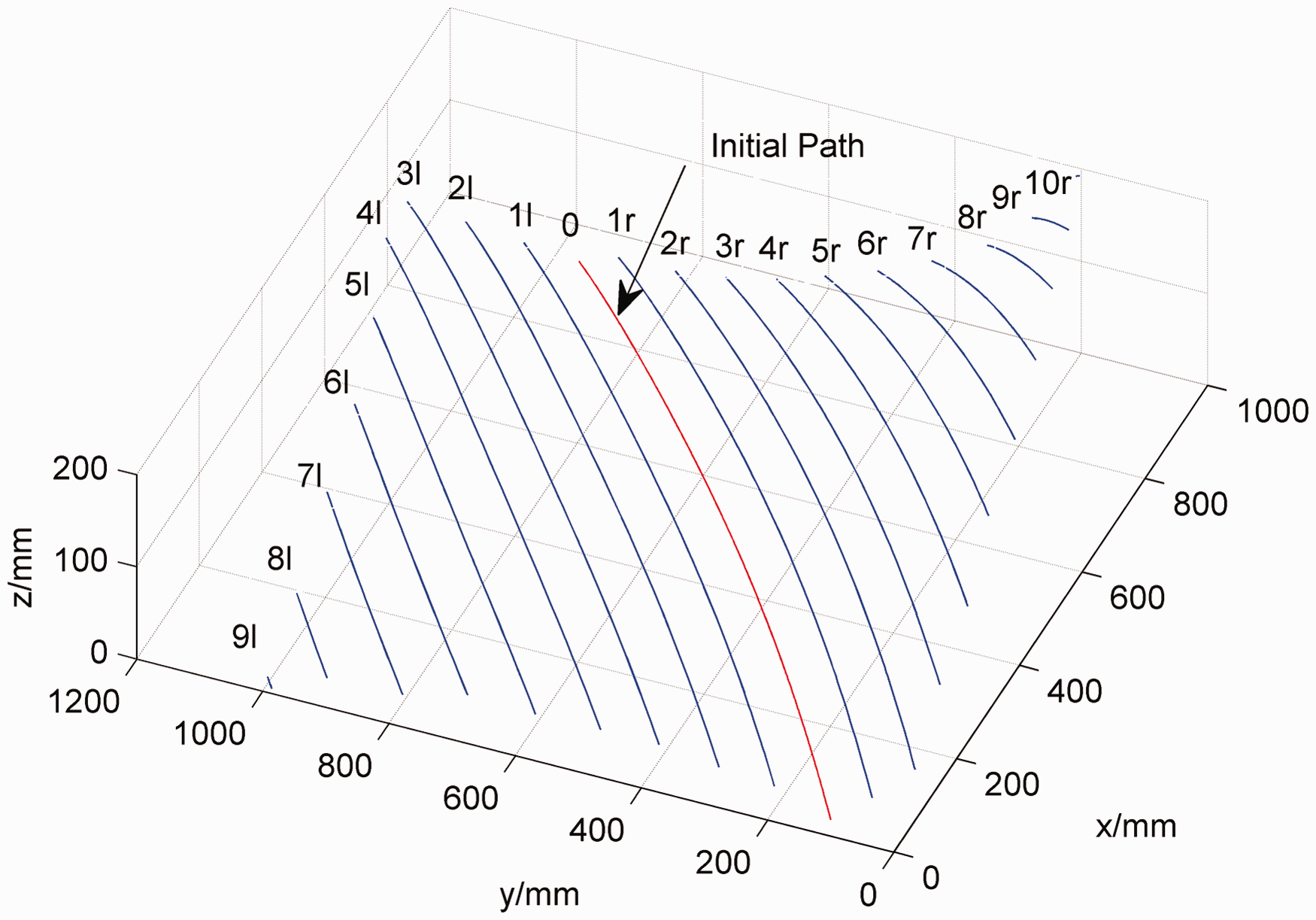
The placement trajectory of the 45° layer with the developed method.
The detailed placement information for the 45° layer with the developed method.
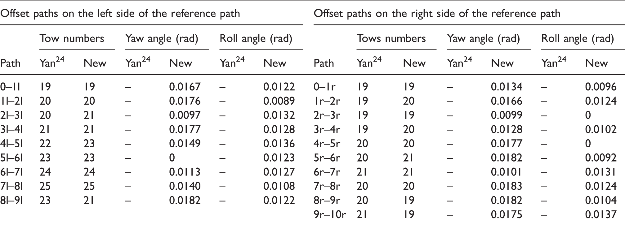
As shown in Table 3, it is found that the tow numbers of the path 2l-3l and 4l-5l increase compared to Yan. Similarly, that of the path 1r-2r, 3r-4r and so on also increases. The corresponding yaw angles change little. It means the placement width can be improved by fine adjusting the yaw angle. However, the tow numbers of not all paths have changed. There are two major reasons: (1) the compaction roller does not need to yaw at the current point. That is to say, the yaw angle is equal to zero; (2) The actual placement width is increased. The final placement width should be an integral multiple of the tow width, the round operator is conducted. After that, the final placement width may still be equal to the placement width. Although the final placement width has no change, the yaw still contributes to improve the fitness degree between the fibers and mandrel due to the change of h1 and h2. The curve diagram of h1 and h2 for the compaction roller is shown in Figure 13. Results show that h1 and h2 make a fluctuation at the critical distance. The whole process is divided into seven stages. Stages 2, 3 and stages 1, 7 have the same state, which belong to condition 1 and condition 2, respectively. Stage 4 is consistent with condition 5. According to the Table 2, the h1 and h2 after yaw named as
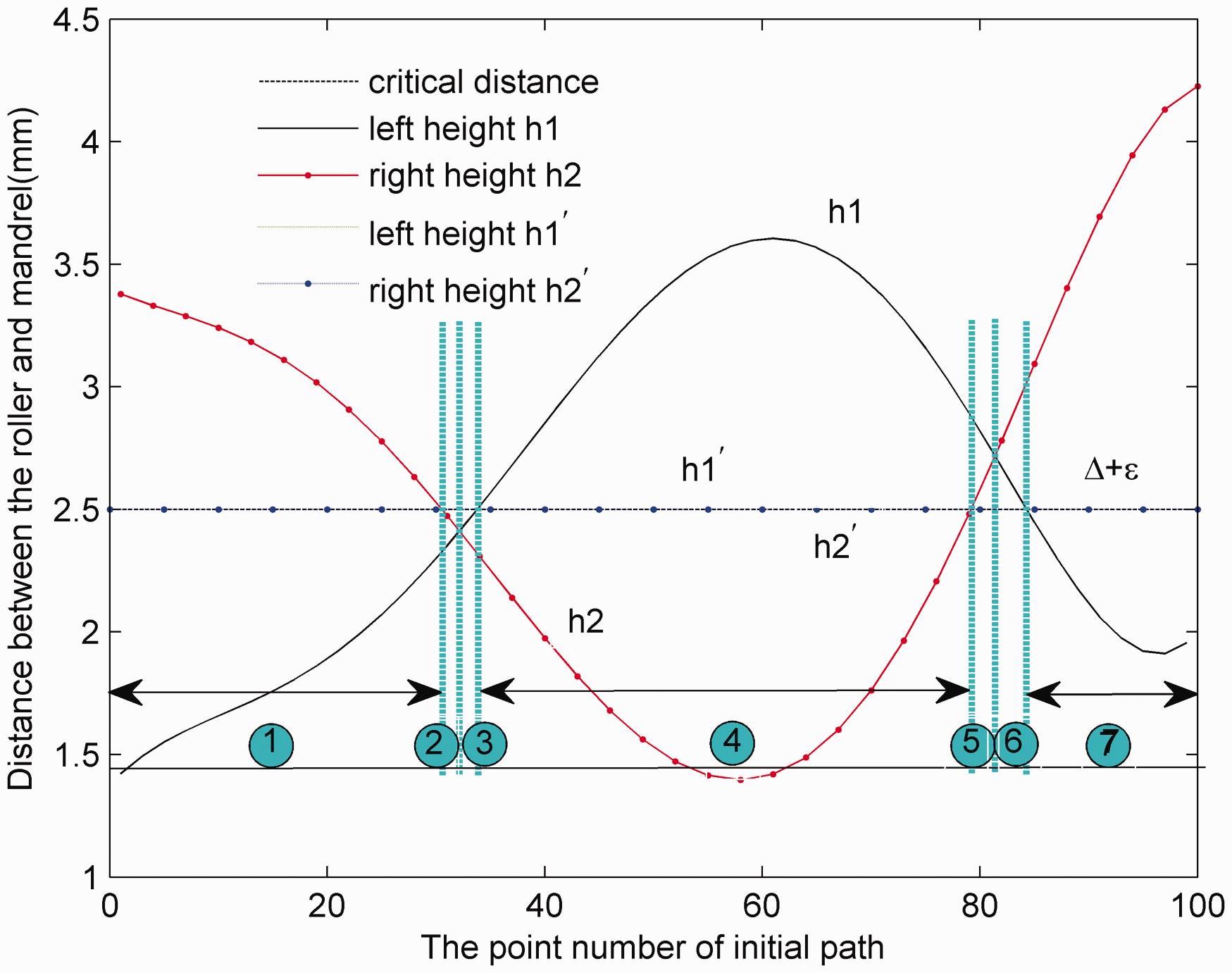
The curve diagram of h1 and h2.
Meanwhile, the compaction roller has a roll angle fine-adjustment for improving the defect fibers’ pull-up. From Table 3, the roll angles of the path 5a-6a, 2b-3b and 4b-5b are equal to zero. It means the fitness degree between the tows and mandrel can meet the placement requirements, and the fiber pull-up is decreased. However, the roll angles of other paths range from 0.0089 rad to 0.0137 rad. It means that there has a micro rotational angle and contributes to improve the fiber pull-up defect. The amplitude of the fiber pull-up is changed, shown in Figure 14(a). The plane with value 2.5 mm is a reference plane. When the amplitude of the fiber pull-up is greater than 2.5 mm, we think that the amplitude is unacceptable for the present composite part. Figure 14(a) shows the pull-up amplitudes from Yan are located over the reference plane. By the roll of the compaction roller, most of the pull-up amplitudes are located under the reference plane. The root mean square errors are 1.4073 and 0.9767, respectively. It means that the attitude motion of the compaction roller can dramatically improve the fiber pull-up. In addition, it is found that some pull-up amplitudes are equal to zero, which reveals that the fibers pull-up is tapered. However, the pull-up amplitudes cannot be considered as the only indicator to measure whether the fiber pull-up is good or not. The severity of the fiber pull-up will be taken into account. It is defined as the aspect ratio named as A/L, where A is the height of the waviness and L is the wavelength, as shown in Figure 7(d). Low aspect ratio means the waviness is flat and high aspect ratio would be tall and sharp. Figure 14 (b) shows the aspect ratios of the developed method are focused on the interval 0.05 to 0.11 and that of Yan range from 0.08 to 0.13. They have different distributions with the mean 0.0675 and 0.0513. Compared with Yan, the aspect ratios of the developed method are significantly smaller. It means that the fiber pull-up can be dramatically improved by the developed method. In addition, some aspect ratios are close after the roll. It reveals that the non-dimensional form of aspect ratio creates the possibility of two different marcels with the same aspect ratio. This is because the wavelength L usually keeps a sliding interval. Therefore, lower aspect ratio is generally not very detrimental to the structure.
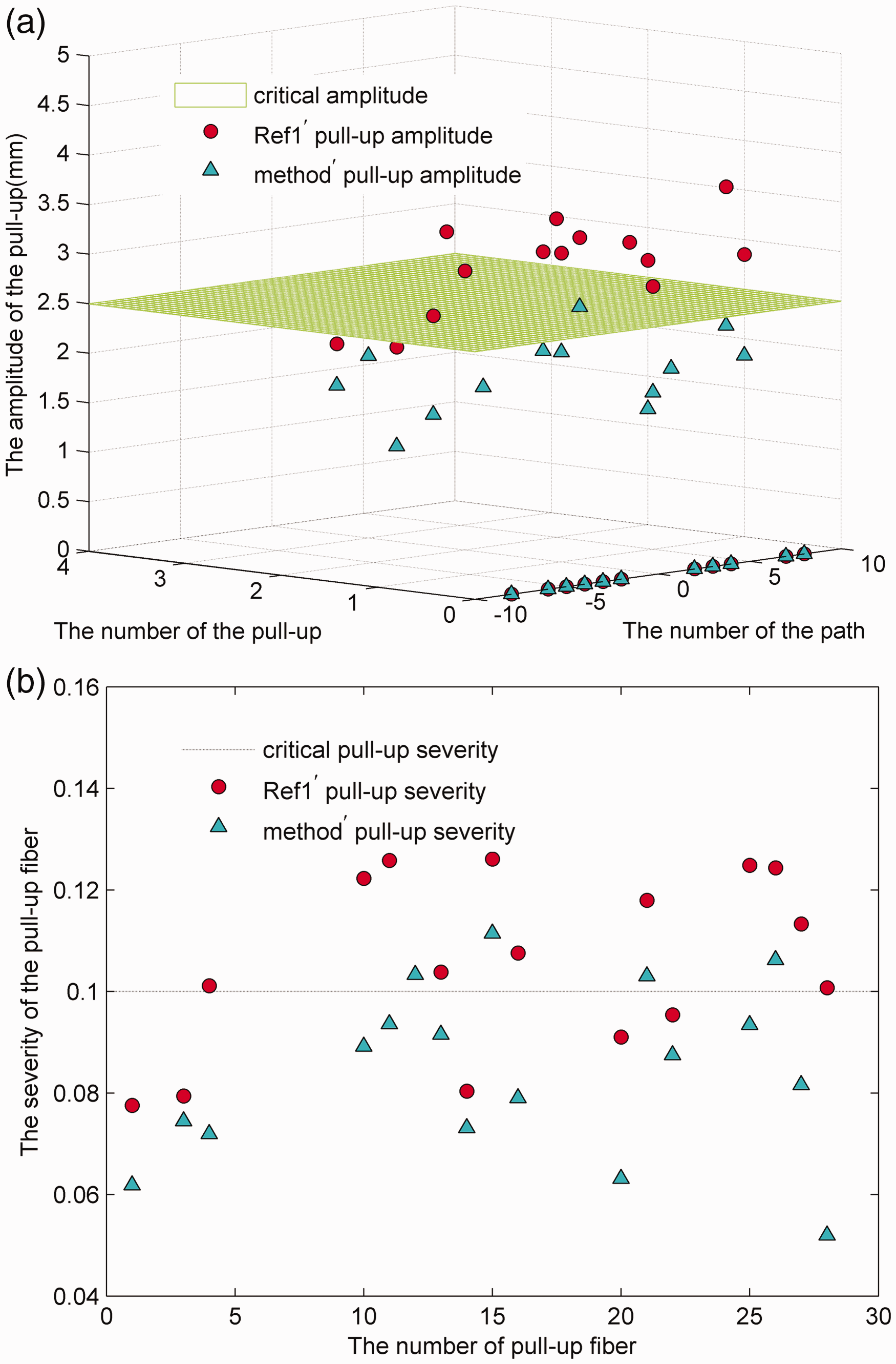
(a) The amplitude of the fiber pull-up. (b) The severity of the fiber pull-up.
To further verify the feasibility of the developed method, an aircraft part is fabricated with a successive stacking sequence [0°, 45°, −45°, and 90°], as shown Figure 15(a). Two methods are used to generate the placement paths. During the placement process, it is found that the fiber pull-up of the Yan is more than that of the developed method, as shown Figure 15(b) and (c). The fitness degree is improved. Results show that the developed method can be good to optimize the placement quality.
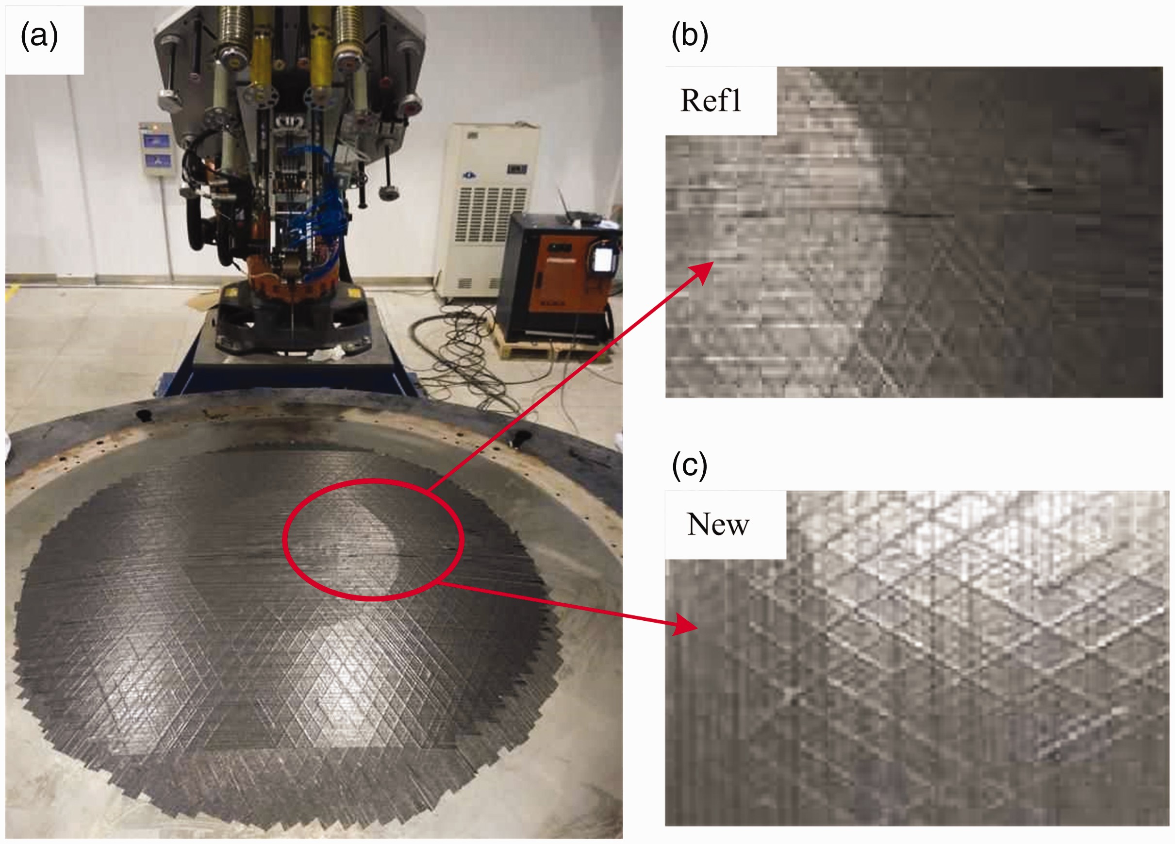
The placement result for an aircraft part.
Conclusions
The attitude in collaboration with the deformation of the compaction roller is an important factor. By fine adjusting the attitude of the compaction roller, the placement defects and trajectory can be improved. The yaw of the compaction roller can improve the placement ability and trajectory. The placement ability of the compaction roller is defined. After that, the yaw angle and position of the compaction roller are calculated by differential geometry. Meanwhile, the yaw distance and placement width of the compaction roller are given after the yaw. The roll of the compaction roller can reduce the fiber pull-up. It ensures that the arc lengths on both course edges are equal as far as possible. The fiber pull-up is described as planar sinusoidal. After that, the roll angle and position of the compaction roller are given. The developed method not only can provide a theoretical foundation for AFP designer but also can give the compensation and optimization after given design to improve the process-induced defects and trajectory.
Footnotes
Declaration of conflicting interests
The author(s) declared no potential conflicts of interest with respect to the research, authorship, and/or publication of this article.
Funding
The author(s) disclosed receipt of the following financial support for the research, authorship, and/or publication of this article: This work was financially supported by the National Natural Science Foundation of China (grant No. 51175261), the Natural Science Foundation of Jiangsu Province of China (grant no. BK20171416), the National Key Basic Research Program of China (973 Program) (grant no. 2014CB046501); and the Specialized Research Fund for the Doctoral Program of Higher Education of China (grant no. 20123218110020).