
Abstract
The development of hull material with ideal properties to meet all the operation requirements has posed the greatest challenge to flying the airship at high altitude for extended periods. Materials developed in our previous study with a laminated structure achieved high strength-to-weight ratio and excellent gas barrier property at a relatively low total weight. To optimize this novel design and obtain a more comprehensive understanding of the laminate properties, a parametric study involving lamination process parameters (temperature and time), and laminate structural parameter (reinforcement fabric construction), was conducted. The effects of lamination parameters on tensile, peel, tear and helium permeability tests were carried out to assess the laminates. It was found that the tensile strength of the laminate is predominantly determined by the fabric reinforcement material properties. The peel and tear strength results showed that increasing the lamination temperature from 185°C to 200°C improved respective strength values. Additionally, the analysis of failure modes and tear propagation suggested that laminate samples with progressive failure have better tear resistant property over those with brutal failure. Extremely low helium permeability was achieved, yet the gas barrier property was not affected by the lamination process parameters and fabric type.
Keywords
Introduction
With their ability to hover in stationary position at altitudes of 20 km for extended periods of time, High Altitude Airships (HAAs) are extremely useful for a wide range of applications. Real-time border surveillance, reinforcement of GPS in heavy traffic areas and analysis of coastal erosion can be achieved effortlessly at such high altitude. Moreover, HAAs can be a cheaper alternative to satellites for meteorological analysis and natural disaster management. In this information era, another promising application of HAAs is to enhance access to mobile internet service and to provide good connections in deserted, difficult-to-access areas, and facilitating globalization of internet connectedness 1 . However, despite tremendous interest in the development of these airships, the past attempts have failed. To date, no HHA has flown at stratospheric altitudes for more than 8 h 2 . The first stratospheric powered airship flight took place in the late 1960s, reaching 20.4 km (67k ft.) for 2 hours with a five pounds payload 3 . In 2005, Raven Industries announced a record of an eight-hour flight of a powered stratospheric airship, reaching the altitude of 20 km (66k ft.).
Due to strict size and weight requirements of HAAs, the non-rigid airship has greater feasibility and advantages over rigid or semi-rigid airships. For non-rigid airships, the hull material is the major structural elements, which contain the lifting gas and keep the aerodynamic shape (Miller & Mandel 2000). Although great advances in strength and functions have been made in airship fabric technologies over the last decades, an airship flying at high altitude has unique standards that demand further improvements on material properties. Major challenge remains in the development of a lightweight yet strong material which is capable of containing lifting gas and enduring harsh stratospheric conditions (temperature variation, UV, ozone, etc.). As suggested by Korea Aerospace Research Institute (KARI), requirements of the hull materials for a 200 m long, 50 m in maximum diameter, and helium inflated HAA include breaking strength higher than 883 N/cm, area density lower than 180 gsm, and helium permeation rate less than 2000 cc/m 2 .24 h.0.1 MPa at ambient temperature 4 . The strength-to-weight ratio of the hull material limits the feasible size of a non-rigid airship. Besides the aerodynamic stresses, hoop stresses from the gas pressure differential also rise with diameter, and in a non-rigid airship, the diameter must be large to resist hull-bending moments 5 . In addition, a HAA is required to be large in volume to produce enough lifting force in stratosphere where the air is rarefied. A desirable HAA must stay aloft for a period of months to years to provide valuable and consistent services. Stronger yet lighter materials are required to build a HAA to optimal dimensions. The high ozone concentration and intense UV radiation in the stratosphere can deteriorate hull material properties over time. Helium, which is a monatomic gas and has the smallest molecular diameter of all gases, is the preferred choice for the lifting gas to provide buoyancy. However, leakage of helium gas through materials cannot be completely eliminated because helium molecules can permeate as well as diffuse 6 through hull materials over time. Consequently, development of hull materials that prevents the leakage of the lifting gas remains a challenging. The only accessible helium permeability data reported in the literature is 115 cc/m 2 .24 h.0.1 MPa, obtained from a laminated material with Aluminum deposited PET film 7 . The upper limit of the acceptable helium permeability falls at 80 cc/m 2 .24 h.0.1 MPa in order to maintain the high-altitude airship in the stratosphere for sufficiently long duration (1–3 years). However, considering the helium leakage to be exacerbated over time, an ideal target of the initial material helium permeation rate should be as low as possible. High tear resistance is also necessary to maximize damage tolerance and prevent catastrophic tear propagation. Low creep is another important property for the hull, so that that the shape of the hull can be maintained throughout service life of a HAA. All these requirements cannot be fulfilled by one single material, and therefore requires a laminated multi-layer composite design approach. The composite laminate design typically consists of load-bearing/strength component, gas barrier/retention element and environmental/weathering resistant layers, which need to be strongly bonded together with an adhesive that allows for ease of laminate manufacturing and seaming 6 .
High-performance fibers and polymeric films are typically used for HAA hull material development. Most recent examples in the literatures4,7–15 are mainly laminated or coated multi-layer structures with high-performance fibers including Kevlar®, VectranTM and Zylon® as the load-bearing component. Tedlar® films with and without Aluminum coating have been applied as the weathering layer, and Mylar® and ethylene vinyl alcohol (EVOH) films have been integrated as gas retention layers. Uni-axial tensile tests for laminated VectranTM fabric were conducted by Kang et al. 4 to collect experimental data and compared with the results estimated by the geometrically nonlinear finite element analyses. The typical stress-strain curve of this type of material is with significant nonlinearity indicating an increasing modulus with the increase of tensile strain. It was also observed that the steady-state stiffness modulus was significantly higher at cryogenic temperature comparing with that at room temperature, which agrees well with the stiffening of VectranTM fibers at a cryogenic temperature. Nakadate et al. 16 also observed similar behavior of Zylon® reinforced airship laminate materials, suggesting that the high temperature would cause the decrease in tensile strength. With their systematic weathering study, it was concluded that the primary factor causing the decrease of Zylon® laminate tensile strength was high humidity. With Kevlar® fabrics as reinforcement in the hull material, Meng et al. 15 investigated the failure modes of uni-axial tensile testing by observing SEM images of fracture samples. Two distinct failure modes of the airship hull material were identified as interface failure and fiber bundle fracture. The failure mode of debonding between films and fabrics correlated well with the force-displacement curve. In the work of Cao X and Gao G 7 , two types of Zylon® based airship hull materials were evaluated with one of them being laminated with Al-PET films. The Helium permeabilities were tested, and the results showed that this performance would be significantly affected by the Al-membranes. A more recent research 17 using ultra-high molecular weight polyethylene fabrics as the airship material strength element investigated the effects of the pulling rate, the initial crack length, and the initial crack orientation on the materials’ tearing tensile strength. It was observed that the woven textile fabrics have substantial sensitivity to the crack orientation and initial crack length, whereas the tensile pulling rate shows minimal sensitivity to samples under uni-axial tensile condition. In a recent review paper 1 , the mechanical properties of a large number of airship materials published in the literatures were compared and contrasted. Generally, Zylon® fiber is predominantly used to form the load-bearing layer for laminated hull material. Based on the evaluations of tensile strength and weight, a significant increase of strength-to-weight ratio is observed from the Zylon® fabric reinforced hull materials compared with those reinforced by other fibers and fabrics 1 .
In our earlier work 18 , a laminated flexible composite structure which consists of Zylon® (PBO) fiber reinforcement, Mylar® (PET) and Kapton® (PI) films with vacuum deposited aluminum (VDA) coatings, and ethylene vinyl-alcohol copolymer (EVOH) film adhesive, was produced using prototype equipment, achieving high strength-to-weight ratio and excellent gas barrier property at a relatively low total weight. The laminate achieved a strength-to-weight ratio of 633 kN.m/kg with a basis weight of 116.9 gsm, which is the stronger than any hull laminate material in the 100–120 gsm range reported in previous works by other researchers. With this new material combinations and design concept, it is important to understand how the process parameters can affect the lamination quality and overall performance of the laminated products for HAA application. There is no published work on a parametric study of HAA hull material formation process and comprehensive material evaluations. With no published work addressing this subject, the objective of this work is to conduct a parametric study of the lamination process and perform a range of critical tests to investigate the effects of lamination parameters, that is, temperature and time, as well as the fabric structure on the overall properties of the laminate samples. Ultimately, the optimal parameter combination of the lamination process is identified to produce best composite laminate materials for HAA applications.
Experimental
Material and Process
Figure 1 displays the appearance and structure of the new lightweight laminated hull material mentioned earlier, exhibiting metallic look on both sides with good flexibility. The structural design of this hull material is shown in Figure 1b, featuring carefully designed load bearing, gas barrier, weathering and adhesive layers. One of the most important principles of material selection and design is to achieve high strengthen-to-weight ratio at the lowest weight possible. Zylon® (PBO) is known to provide the highest specific strength and modulus among the commercially available high-performance fibers. With excellent creep resistant property validated in our preliminary work
18
, these yarns from Zylon® fibers are selected to form the fabric reinforcement in the laminate structure. In this work, multi-filament Zylon® yarns (99 fil) with a linear density of 150 denier were used to weave high strength and lightweight woven fabrics with low thickness. The finest Zylon® yarns used in the public literature was limited to 250 denier. The polyimide film (Kapton®) is a multi-functional material that is ozone stable, gas tight, and high temperature resistant. The polyimide (PI) film used in this work, 50 DE Plasma MBS Kapton/DB25, is a 50-gauge (13.2 μm, 21 gsm) sample that is aluminized on both surfaces and deposited with corrosion resistant coating (CRC) on one side. It offers excellent physical, thermal, and optical properties with low emittance and solar absorptance values. The polyester (PET) film (Mylar®), is a 25-gauge (6.35 μm, 8 gsm) sample that is aluminized on one surface. The thin layers of vacuum deposited aluminum (VDA) coating applied to the polymeric films prior to lamination enhances the gas barrier property with minimal weight addition and effectively reflect the heat and UV radiations. EVOH has outstanding gas barrier property as well as strong bonding strength to metallic surfaces. The EF-F grade EVOH film used in this work has a thickness of 15 μm, areal density of 18 gsm and melting point of 183°C. The total weight of laminated samples falls in the range of 116.9–117.6 gsm depending on the fiber reinforcement used. (a) Macroscopic image of the new laminated hull material and (b) Schematic of laminate structure.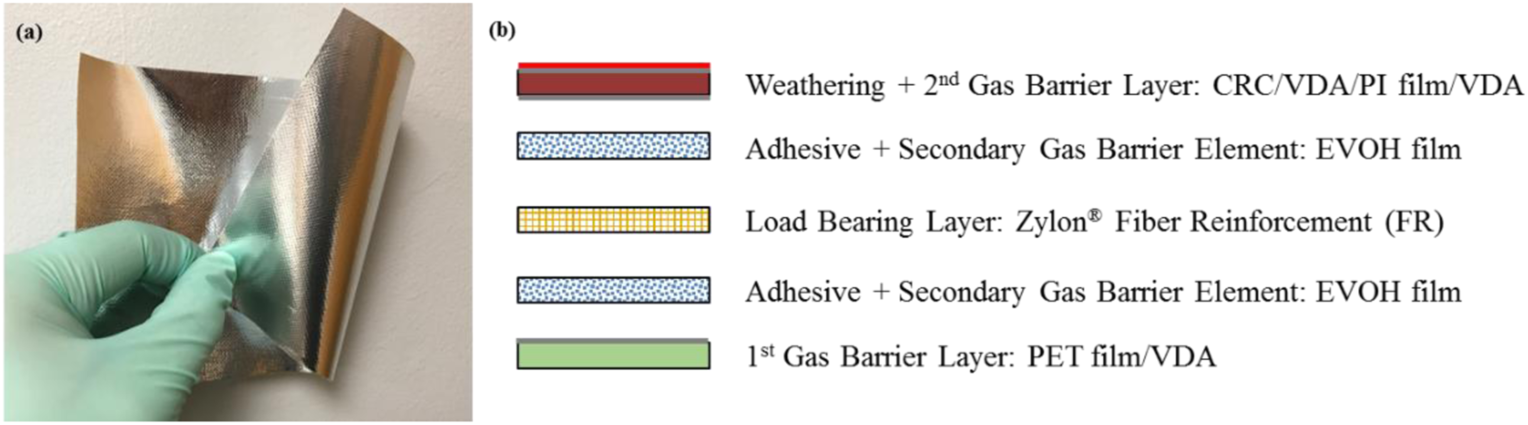
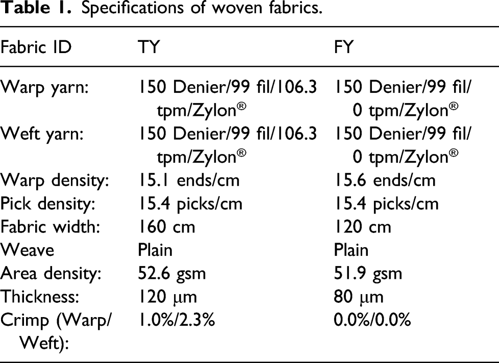
Specifications of woven fabrics.
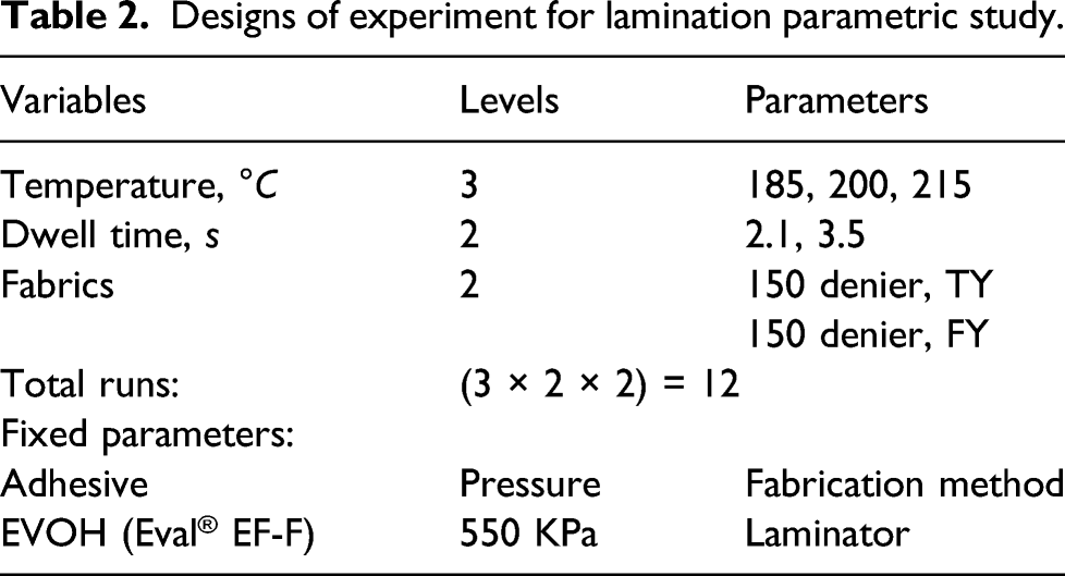
Designs of experiment for lamination parametric study.
The lamination process was conducted on the Pratix OK-12L Seamless Teflon Belt Drum Laminator available at the Textile Technology and Filament Lab., Wilson College of Textiles, North Carolina State University, shown in Figure 2. All components of the laminate were properly laid and secured between two brownish Teflon sheets, and then passed through the laminator. To maximize the tensile strength of produced laminate samples in the weft direction (airship hull hoop direction), the woven fabrics were fed to the laminator with the weft yarns along the machine direction to substantially remove the crimps. With the decrease of weft yarn crimps, the crimp interchange behavior in woven structures would cause the crimps in the warp yarn direction to increase. Pratix OK-12L Seamless Teflon Belt Drum Laminator (close-up: materials being fed into the laminator between two brownish Teflon sheets).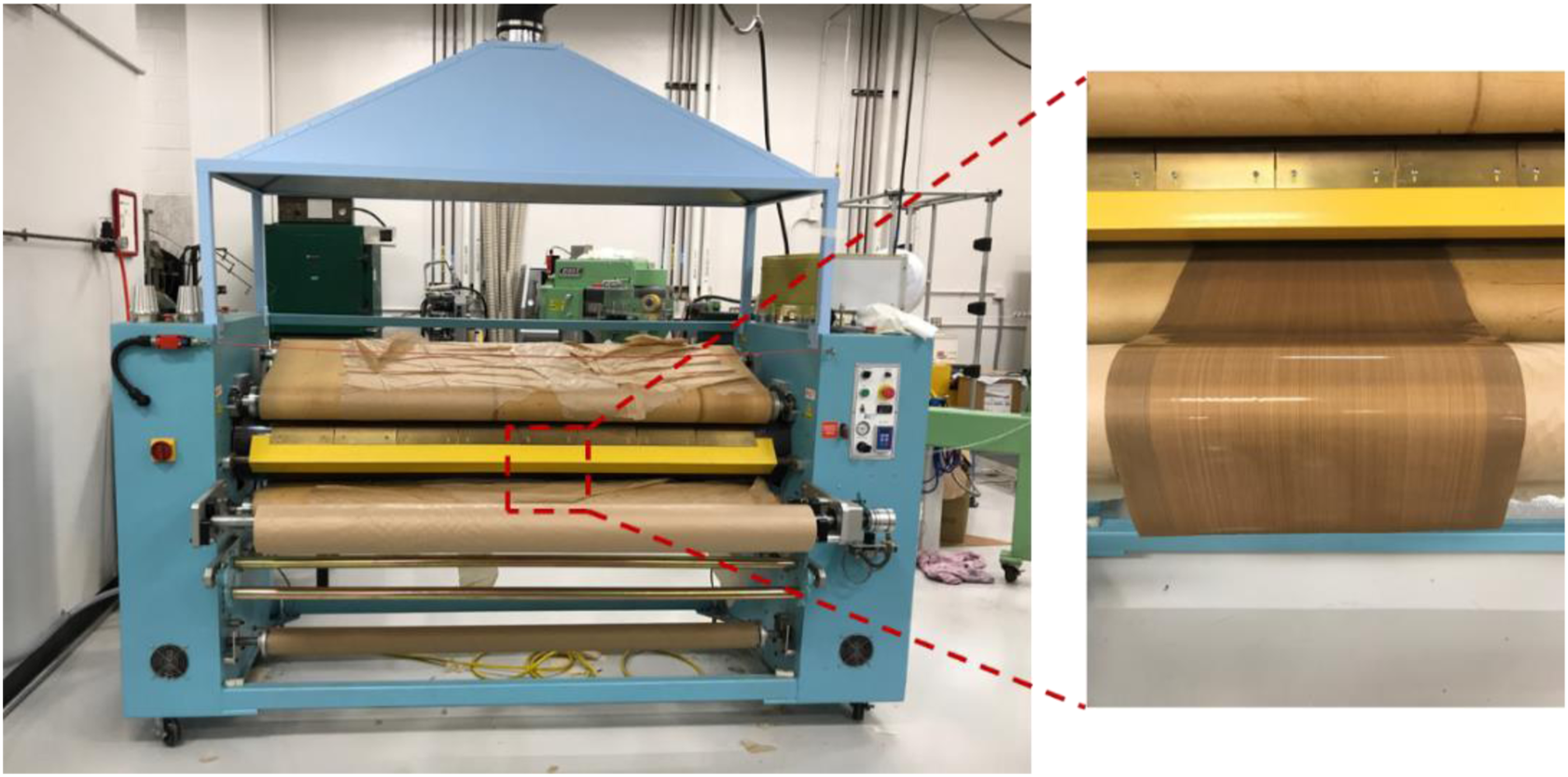
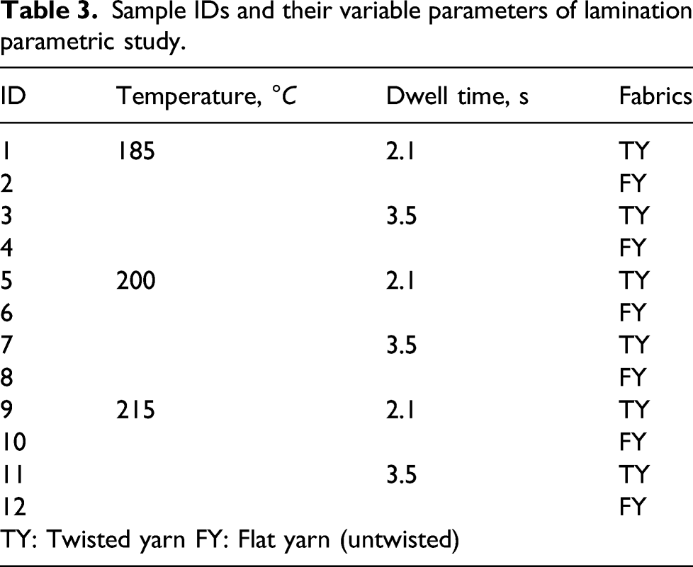
Sample IDs and their variable parameters of lamination parametric study.
Testing
As mechanical and gas barrier properties are the most fundamental standard to qualify a HAA airship material. A range of mechanical tests as well as helium permeation tests were accomplished to thoroughly evaluate the laminate samples.
T-peel test
To characterize adhesion properties of the laminate material, T-peel test was applied following ASTM D1876
20
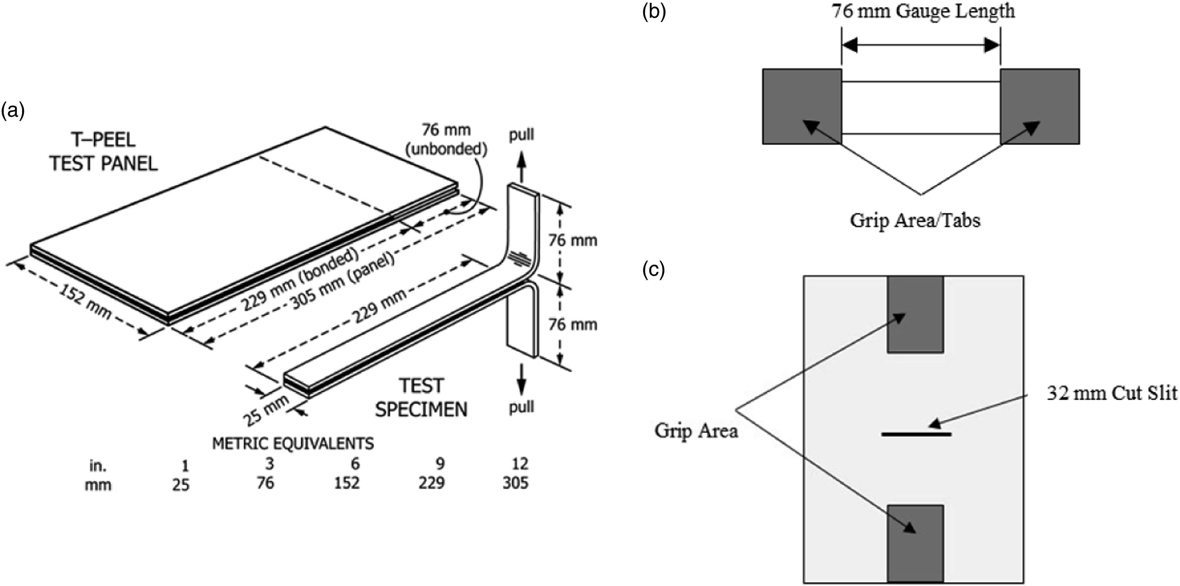
on a MTS Q-Test/5 Universal Testing Machine, shown in Figure 3a. This method is primarily intended for determining the relative peel resistance of adhesive bonds between flexible adherents by means of a T-shape specimen. A schematic of T-peel test specimens is shown in Figure 4a. Per the testing method, the peel strength/resistance of a specimen will be calculated by averaging the load values over at least a 12.7 cm (5 inch) length of the bond line after the initial peak. Mechanical Testing Setups, showing specimens for (a) central slit tear test, (b) tensile test, and (c) T-peel test. Schematic diagram of (a) Test panel and specimen for T-peel test
20
, (b) a tensile specimen, and (c) a central cut-slit tear specimen.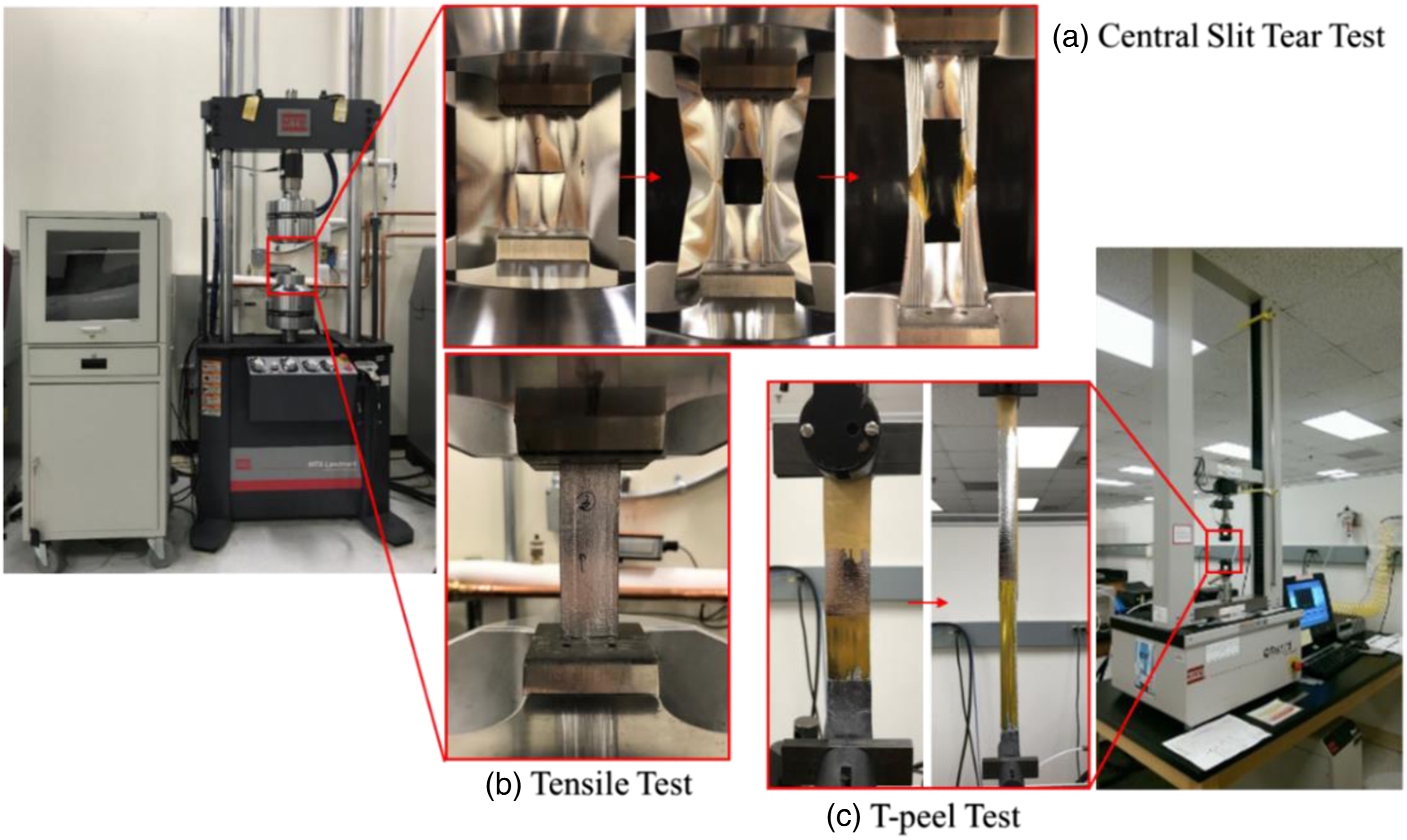
To make the laminate samples for T-peel test, a piece of ultra-thin Teflon sheet was placed at targeted areas to prevent the EVOH film adhesives from bonding the PI and PET films to the fabric. Due to the weak strength of the ultra-thin PET film, proper peeling cannot be initiated because the film ruptures at the borderline between laminated and non-laminated areas. Thus, only the adhesion of EVOH on PI side can be evaluated through T-peel Test. Five specimens from each group of samples were tested with the peel being along the weft direction of the woven fabric.
Tensile test
Tensile strength of the laminate specimen was determined according to ASTM standard D5035 21 . Uni-axial tensile tests were performed on the MTS Landmark servo hydraulic 250 kN testing machine (Figure 3b) at a constant rate of 0.3 m/min (12 inch/min) up to failure of the specimens. The specimens are specified to be 15.24 cm (6 inch) long and 2.54 cm (1 inch) wide, with a gauge length of 7.62 cm (3 inch) as shown in Figure 4b. Paper tabs were glued to the grip area (highlighted in Figure 4b) to prevent specimen slippage and stress concentration. Three specimens from each sample were tested in both fabric warp and weft directions.
Tear test
The tear strength of the laminate material was measured using the central cut-slit tear testing method described in MIL-C-21189 22 on the MTS Landmark servo hydraulic 250 kN testing machine, shown in Figure 3a. A schematic diagram of a tear specimen is shown in Figure 4c. The specimens are required to be 15.24 cm (6 inch) long and 10.16 cm (4 inch) wide. A 3.175 cm (1.25 inch) long slit was made with a razor across the center of the laminate specimen perpendicular to the direction of the load. The testing speed is suggested as 3.048 ± 0.127 m/min (12.0 ± 0.5 inch/min). Three specimens in both warp and weft directions from each group of samples were tested. The tear strength is calculated by averaging the load of the five highest recorded peaks during tear propagation 22 . It is suggested in Ref. 23 that data collected from this test method provides valuable information for comparison between two fabrics as well as for quality control purpose.
Helium permeation test
Helium permeation tests were conducted on the Labthink® PERME® VAC-V2 gas permeability tester (shown in Figure 5), following the M – Manometric method provided in ASTM D1434
24
. During the test, a pressure difference of 0.1 MPa is formed between two sides of the specimen. After the transmitting process has become stable, the barrier property of material can be calculated with the obtained pressure variation of lower chamber. The gas of interest for this work is helium. The test temperature is controlled by water bath at 23°C. Three wrinkle-free specimens were tested for each sample. The Labthink® PERME® VAC-V2 gas permeability tester (close-up: a wrinkle-free laminate specimen mounted on the testing chamber with PET side facing toward gas inlet).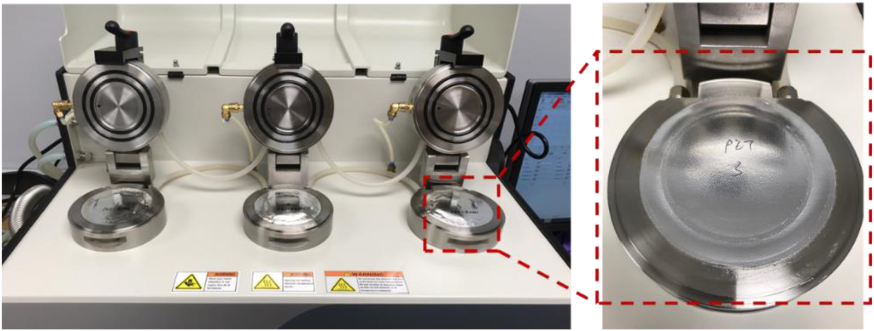
Results and Discussions
Effects of lamination parameters on tensile property
Representative uni-axial stress-strain curves of laminate specimens in the warp and weft directions are shown in Figure 6. The nominal stress of this type of thin laminate composite is calculated as load (N) over specimen width (cm). So, the ultimate stress is obtained at the peak load of the tensile test in N/cm. Typical stress versus strain curves of laminate specimens in warp and weft directions.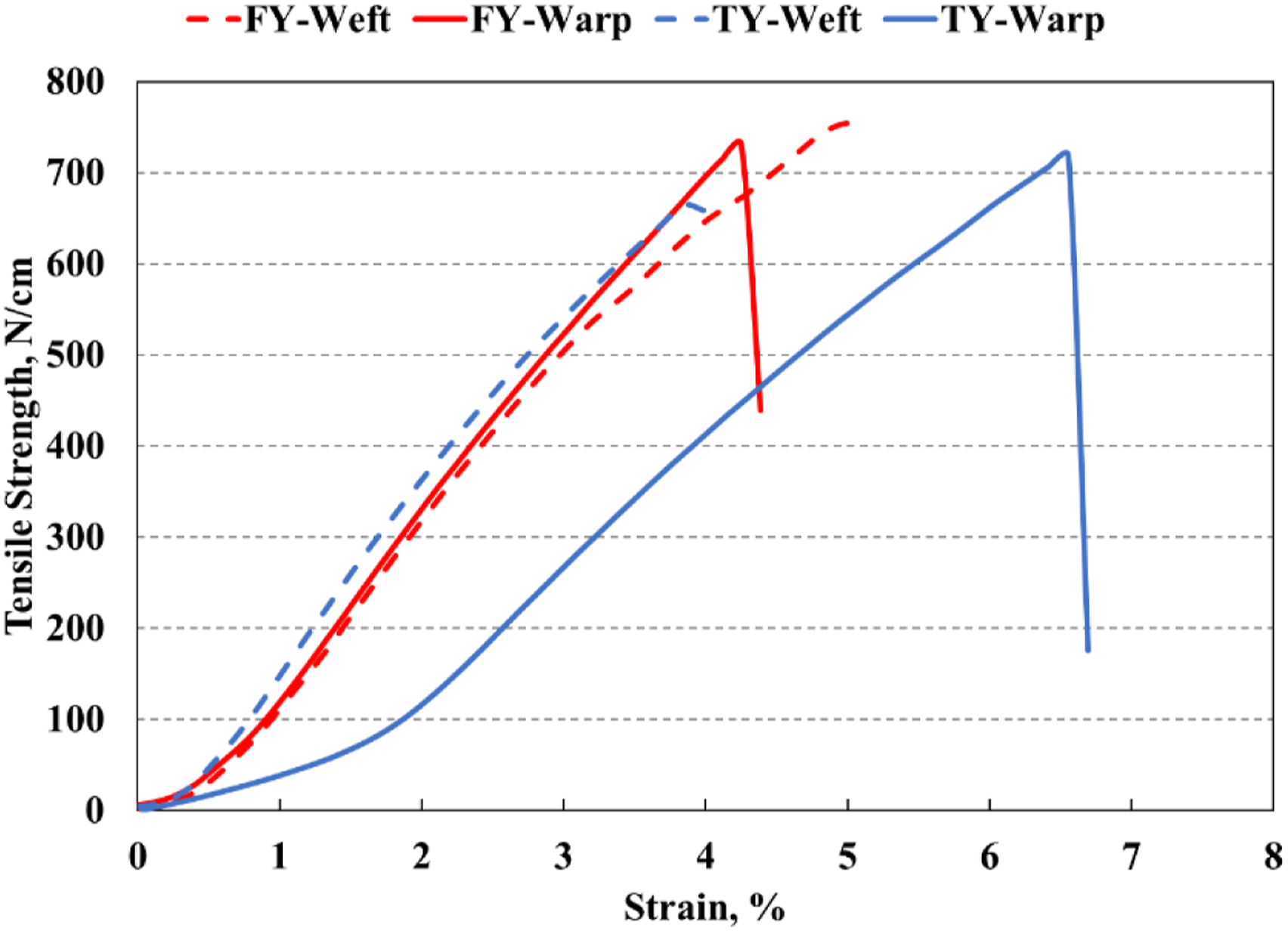
There are three distinct regions in the stress-strain curves of both warp and weft directions: a de-crimping region, a non-linear region, and a linear region with high stiffness. In the de-crimping region, the stress-strain graph shows a relatively small increase in stress with increase in strain. The load required is essentially to straighten the yarns by removing the crimp due to weave interlacing. At the low strain region, the structural woven fabric layer and other functional layers are extended together and the whole laminate exhibits no damage. As the sample is pulled continually, the straightened yarns start to take more load and the yarns are being elongated. So, the stress-strain curve displays an increased slope compared with crimp region to form a non-linear region. Debonding at film-fabric interface may start to take place at this stage for samples with poor interlayer adhesion. Before reaching the maximum tensile strength, the stress-strain curves exhibit linearity in the high stiffness region. The woven fabric layer becomes the major load-bearing structure of the laminate when the films, with poor bonding, may continue to delaminate in varying degrees and locations. As is shown in Figure 6, the stress-strain curves of FY samples (in red) and TY-weft sample (blue dash line) are almost identical, showing minimal crimp regions due to low crimp of yarns in FY fabrics and along weft direction in TY fabrics. With more crimp of the warp yarns in TY fabrics, the stress-strain curve (blue solid line) is observed to have a more extended crimp region, leading to a higher failure strain. Macroscopic damage morphologies of the uni-axial tensile test results with similar mode of failure are shown in Figure 7. In the process of tension, Zylon® yarns bear the major stress. Zylon® yarn fractures were the major failure mode of the specimens due to its low strain at failure compared to the other constituents of the laminate. Fractures tend to occur close to the grip where stress concentration is high. Minor damages of the films were observed for specimens with better adhesion, while more obvious film delamination can be found for specimens with weaker interlayer bonding. Typical modes of failure after tensile test (red arrows showing the fracture area of each specimen).
Laminate tensile test results.
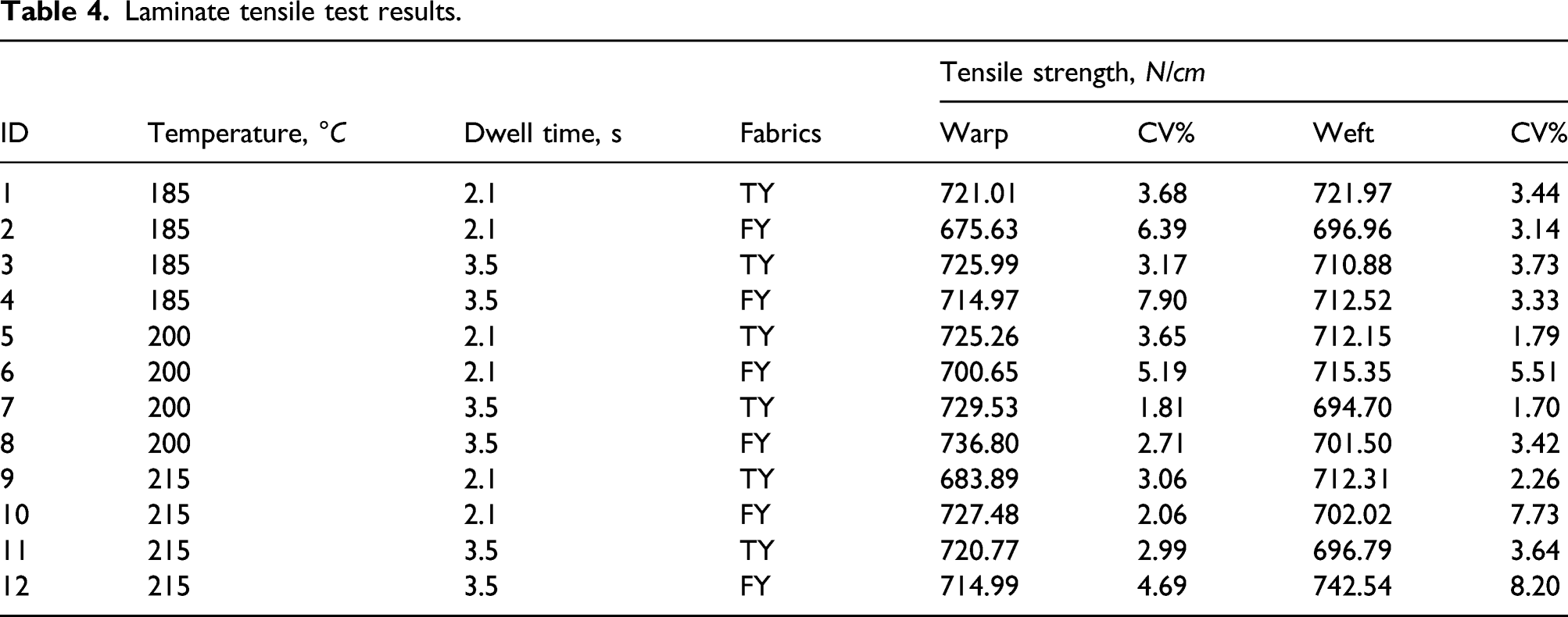
The main effects of the lamination parameters and woven fabric difference are plotted in Figure 8a to c. In Figure 8a to c, the laminate tensile strength, although with certain variations, were very similar regardless of the level of the parameters investigated. The statistical analysis confirmed the observations with all the p-values being higher than α = 0.05, indicating that the tensile strength in both warp and weft directions are not significantly different with the variation of fabric type, lamination temperature, and dwell time. Additionally, the laminates tensile properties are not significantly different from the tensile properties of the control woven fabrics. Details of the statistical analyses are available in Ref. 18. Main effects of (a) Fabric types, (b) Temperature, (c) Dwell time on tensile strength of laminate in warp and weft directions, and (d) Tensile strength of woven fabrics in warp and weft direction.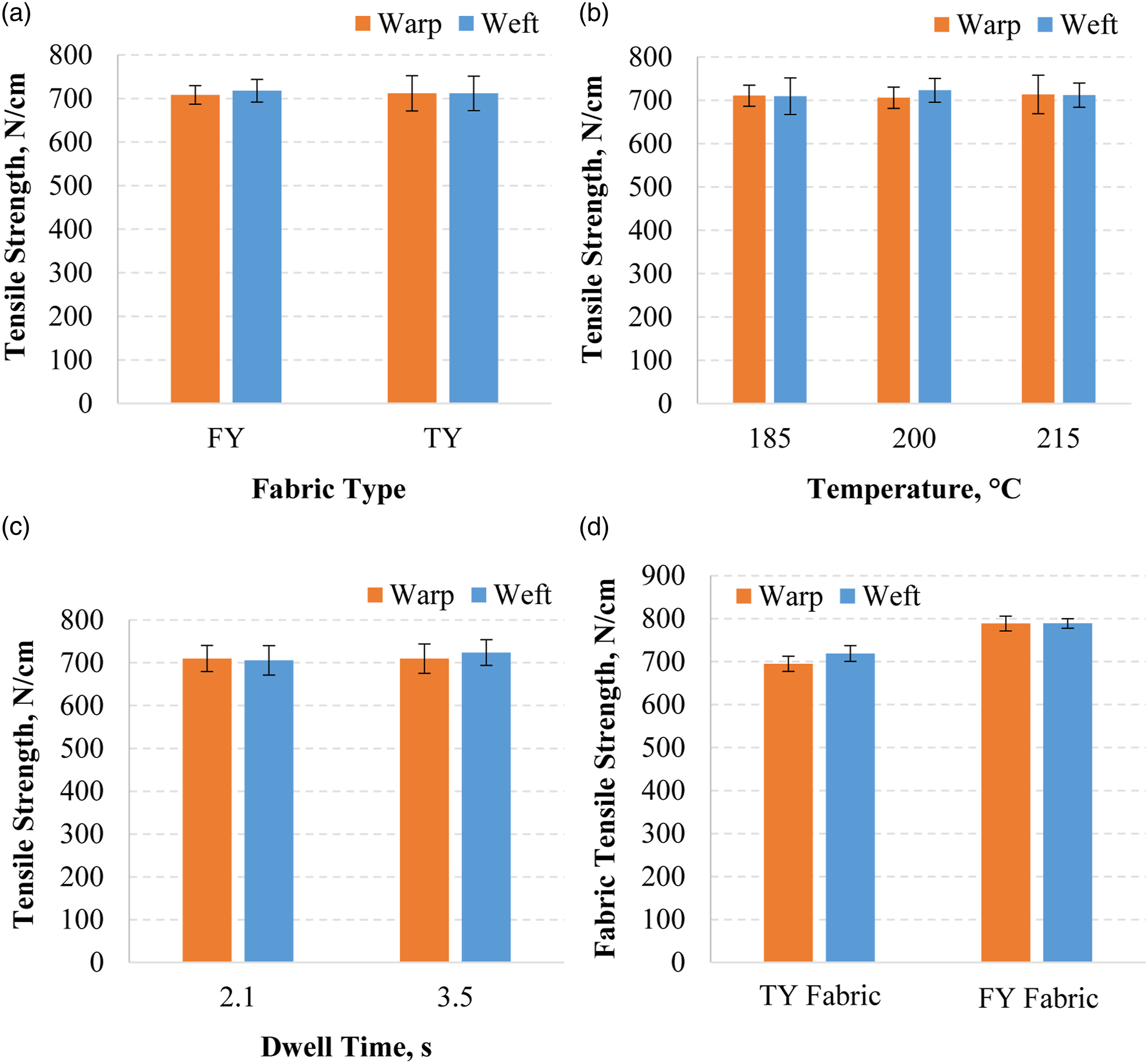
High tenacity fabrics reinforcement is the primary load-bearing component. Therefore, it is reasonable to believe that the tensile properties of laminates are predominantly determined by the inherent properties of the reinforcement fabric. The tensile strength of TY and FY woven fabrics were measured upon the receipt of the fabric rolls. Specimens were taken from wrinkle-free regions which are at least 2 inch away from the selvedges. As is shown in Figure 8d, the tensile strength of both TY and FY woven fabrics are similar in warp and weft direction, which is in agreement with the laminate samples. Therefore, it is safe to conclude that the tensile strength of the laminate is predominantly determined by the intrinsic fabric and yarn properties and is thus not affected by the lamination parameters. The only more obvious difference of the higher crimp on warp yarns in TY fabric tends to cause its laminate to be able to stretch more in the warp direction. As shown in Figure 6, the modulus of FY warp and weft samples are similar to each other, while the initial modulus of TY warp sample is significantly lower than TY weft sample. When balanced properties are required in warp and weft directions, FY fabrics should be preferred over TY fabrics.
Effects of lamination parameters on peel property
In the case of T-peel test of laminate specimens, the force required to peel the PI film off from the Zylon® woven fabric was measured continuously along the peel propagation. As is clarified in the experimental part, the peel resistance is determined over at least a 12.7 cm (5 inch) length of the bond line after the initial peak. However, the failure analysis of the specimens showed that the PI films were torn and fractured randomly before a minimum peel propagation of 12.7 cm (5 inch). In these scenarios, the peel strength was calculated based on the effective length of the peel propagation. Figure 9 illustrates the failed T-peel test specimens with complete peel-off of PI film as well as partially peeled, torn, and then fractured PI film. The propagation length before PI film fracture varies from specimen to specimen. A close-up view of the peel initiation region is also shown. It is clearly observed that the major peel failure is the exfoliation of the thin VDA coating from PI film. Apparently, the thin VDA coating is not completely separated from the original PI film substrate. The non-uniform pattern of the VDA peel interface perhaps indicates that the adhesion is not consistent over the entire laminated area. However, it may also be caused by cracking of the VDA coating due to excessive handling. The specimens (from Sample 9) failed after T-peel test with different modes of failure on PI film (close-up: peel initiation region).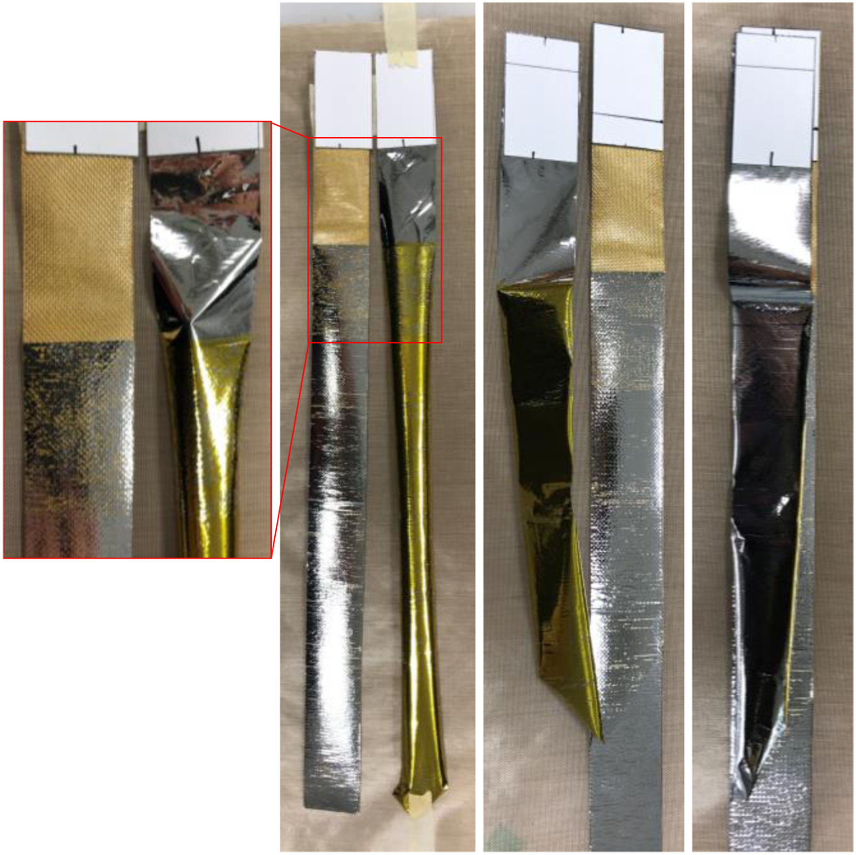
Peel strength of laminate.
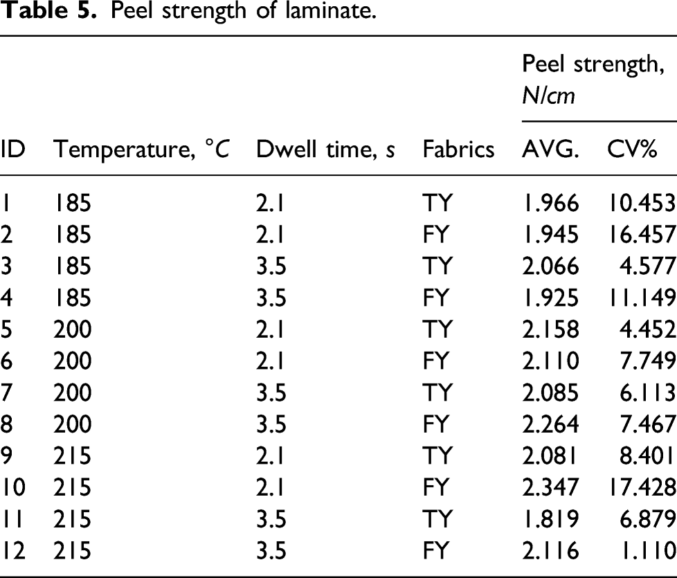
The results of the peel strength of all the specimens were analyzed using univariate analysis of variance to reveal the effect of the lamination parameters (lamination temperature and dwell time) and different woven fabrics on the peel strength of composite laminates. Further, the main effects of all three parameters are plotted in Figure 10a to c. Main effects of (a) Fabric types, (b) Temperature, and (c) Dwell time on peel strength/resistance of laminate.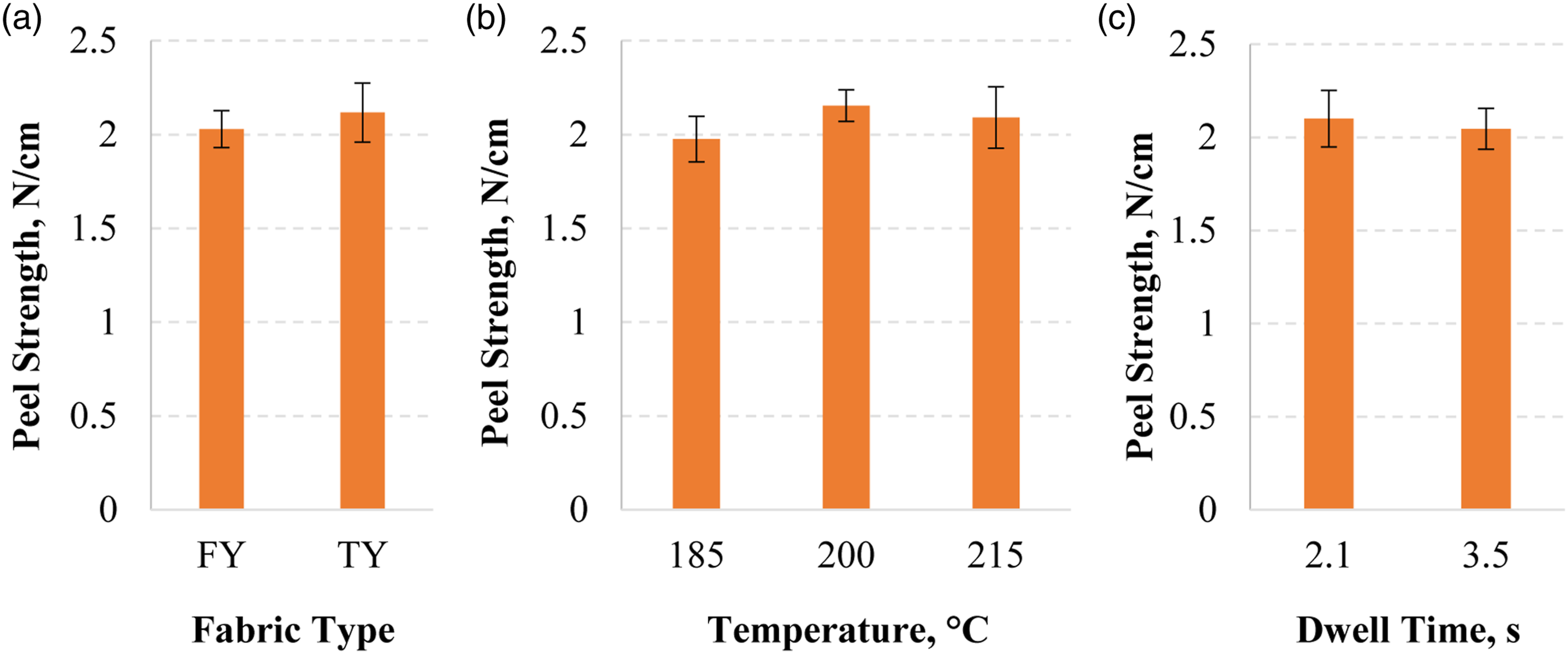
The analysis indicates that there is no significant difference between the peel strength of the laminates made with different woven fabrics in Figure 10a. Whereas the statistical analysis revealed that the peel strength of the laminate sample made at 200°C is significantly higher than the sample processed at 185°C. However, there was no significant change in peel strength when the temperature was further increased to 215°C, as shown in Figure 10b. For the different dwell times during the lamination, there is no statistically significant difference in the peel strength as illustrated in Figure 10c. It is speculated that temperatures at exceedingly high level can negatively affect the adhesion property and cause more energy consumption. Therefore, a proper temperature control at around 200°C for lamination can be beneficial to produce laminate materials with better adhesion and therefore high peel strength/resistance.
Effects of lamination parameters on tear property
Laminate tear test results.
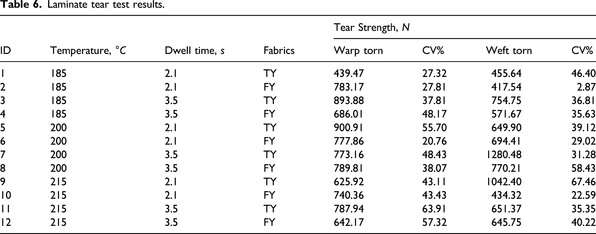
The results of the tear strength of all the specimens were analyzed using univariate analysis of variance, attempting to reveal the effect of the lamination parameters (lamination temperature and dwell time) and different woven fabrics on the tear resistance of composite laminates. The main effects of the lamination parameters and woven fabric type are plotted in Figure 11a to c. The ANOVA results suggest that the tear strength is not affected by the variations of all these three variables, generating a p-value of 0.6014. Figure 11a to c also indicate that there is no statistically significant difference between the tear strength of the laminate samples when comparing all three main effects. However, by performing a Tukey’s multiple mean comparison analysis, it was found that the tear strength of sample laminated at 185°C is significantly lower than that at 200°C. Additionally, it also revealed that the tear strength of sample laminated at 215°C is not statistically different from 200°C. Thus, changing the lamination temperature showed a significant effect on the tear strength as illustrated in Figure 11b. Details of the statistical analyses can be found in Ref. 18. Main effects of (a) Fabric types, (b) Temperature, and (c) Dwell time on tear strength of laminate.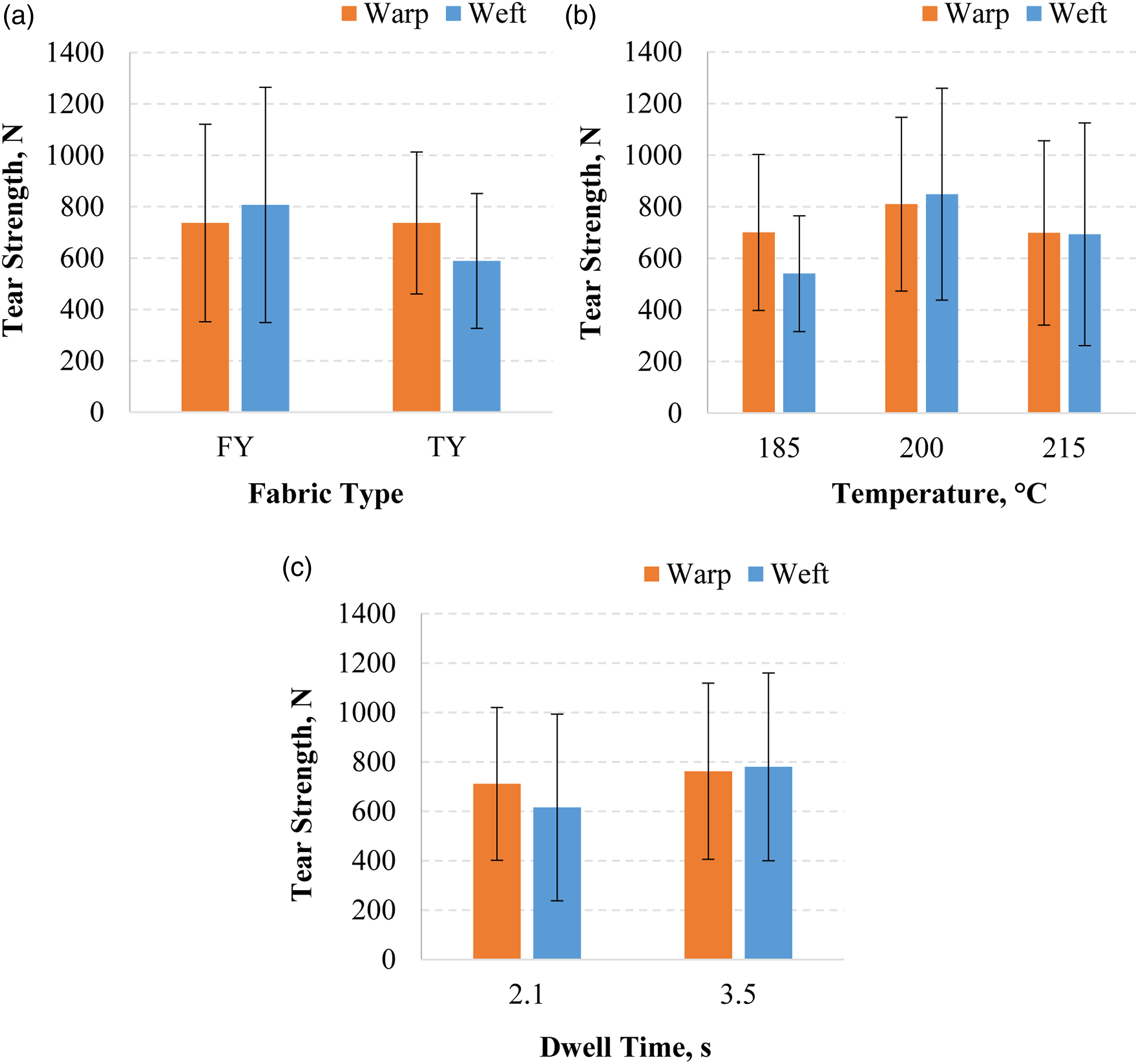
Overall, the statistical analysis of tear strength data unveiled limited information on the tear resistant property of the laminate samples. To further investigate on this matter, the tear failure modes and respective load-displacement tear propagation curves need to be analyzed. Concerning laminated fabrics, two types of failure modes were mostly observed in the literature for tear propagation with central slit method, namely, progressive failure and brutal failure 27 . Brutal failures always occur in a sudden, with a rapid tear propagation across the specimen where the tear is initiated. A sudden drop of the applied load is therefore associated with this process. As the sample failure is catastrophic, the load at the rupture of first bunch of yarns is usually the maximum load. Then, the load quickly plunges to a low level following the peak. In contrast, the progressive failure usually takes place gradually. Yarns perpendicular to the loading direction are pulled by the tensile load and tend to slide over yarns to be torn (along the loading direction). At the tear tips of the central slit, two triangular del-shaped openings, usually referred to as del-zone 28 , are formed simultaneously. As the yarns slip and jam together adjacent to del-zones, the inter-yarn frictional forces increase and hinder further yarn slipping. The del-zones then reach the maximum size. Further increase of the tensile load will cause the yarns to be ruptured in groups, after which the slipping of yarns perpendicular to loading direction resumes to form next del-zones. Once the first group of yarns break, the initial crack continues to propagate steadfastly and the load either fluctuates at roughly the same level or decreases gradually to the low level 29 . Tear test results showed that only laminate specimens with strong inter-layer adhesions are subject to brutal failure. The tear propagates simultaneously in the structural fabric layer and other laminated film layers, and the edges from tear ruptures of the yarns and films almost completely overlap with each other. However, for samples with relatively weaker bonding, the edges from tear ruptures of the yarns and other laminate films do not overlap well, which can be attributed to yarn slipping. In fact, the adhesion properties of the laminate composite materials directly govern the tear resistant performance. Therefore, tear failure mode analysis could be a reliable way to evaluate tear resistant and adhesion properties of the laminate materials. Specimens with very weak bonding showed great shear deformation inducing more significant sliding and jamming of yarns during tear propagation. Severe delamination between films and fabrics were also observed. The failure modes of theses specimens were not qualified as either brutal or progressive failure, and thus are not discussed in this paper.
Figure 12 shows the load-displacement response of a laminate specimen with strong adhesion. The curve exhibit two distinct regions. Region I is the normal slit opening region where the yarns are only straightened with neither yarn slippage nor yarn fracture. Region II is the tear propagation zone showing load decrease throughout the whole region. For this type of laminate specimen, during the tear propagation, multiple yarns broke almost simultaneously and then the load plunged to a low level rapidly after the peak. This also led to lower overall specimen displacement, less peaks and shorter duration of the plateau region because there is minimal to none sliding of yarns perpendicular to the loading direction over yarns to be torn. Load transfer between these two sets of yarns is efficient, indicating strong adhesion between the fabric reinforcement and the films. Representative load-displacement curve and mode of failure of a typical brutal failure of a central slit laminate specimen with strong adhesion (The specimen shown is from Sample 12).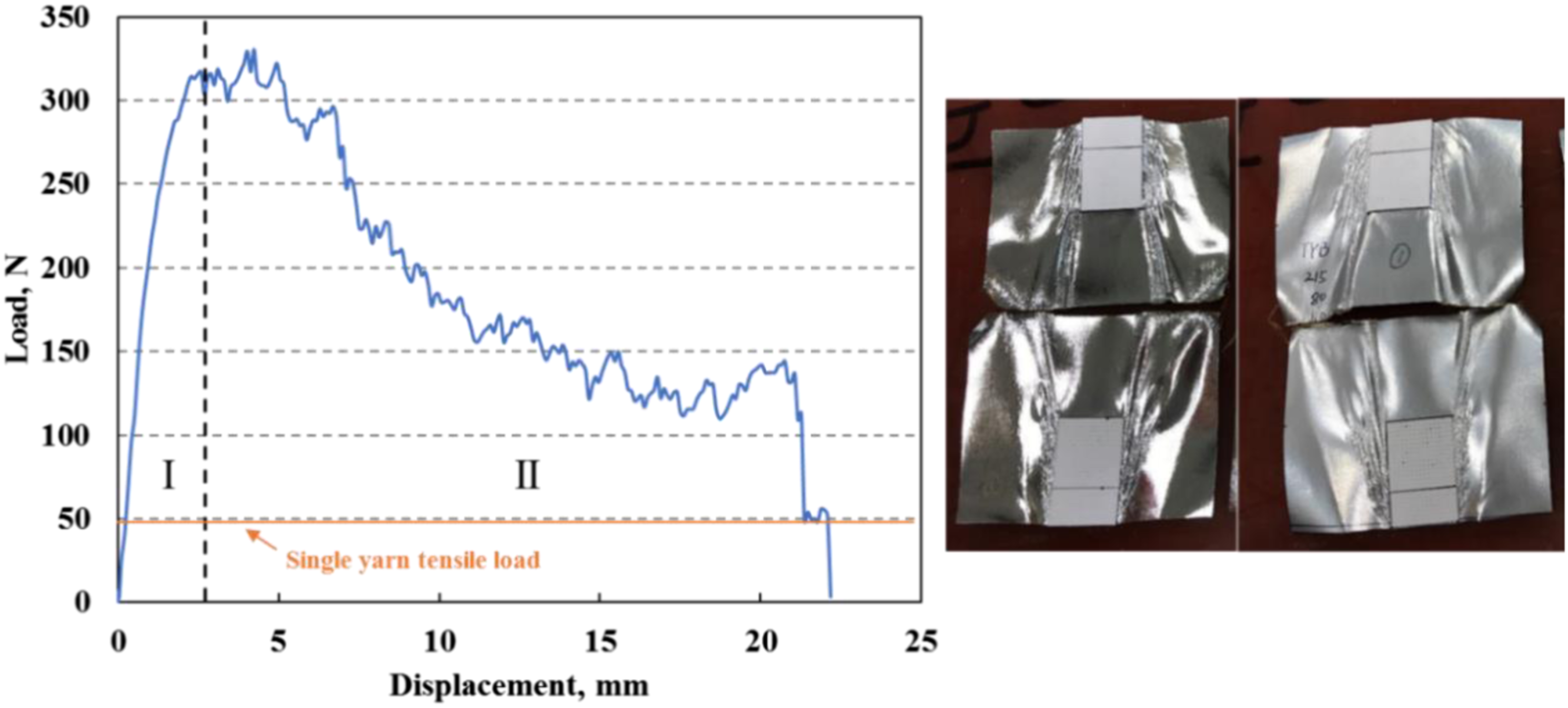
By observing the failed specimen in Figure 12, the yarns in the loading direction break at the tear failure edge and the fracture of the films and yarns coincide very well. The instantaneous nature of failure indicates pure tensile failure of these yarns in the loading direction. This phenomenon is caused by the strong yarn-film adhesion that results in complete locking of yarns when tension was applied. It was also observed that yarns perpendicular to the loading direction did not jam together. This mode of failure is termed as “brutal failure” and is distinct from the progressive tear propagation. The adhesion level of the specimens with “brutal failure” is deemed to be strong.
Another mode of tear behavior is shown in Figure 13. The load-displacement relationship of this type of laminate specimen has three distinct regions. Region I is the normal slit opening region where the yarns in the loading direction are only straightened. Region II is a typical tear propagation zone for progressive failure, showing load fluctuations throughout the whole region, highlighted in a red rectangular. The amplitude of the load fluctuations is larger than single yarn tensile load. Therefore, it is apparent that more than one yarn fractured at the same time during the tear propagation, which is an indication of load sharing of yarns to be torn in the del-zone. At the end, region III is the post-propagation zone exhibiting the failure of the whole specimen. Representative load-displacement curve and mode of failure of a typical immediate tear propagation of a central slit laminate specimen with moderate adhesion (The specimen shown is from Sample 5).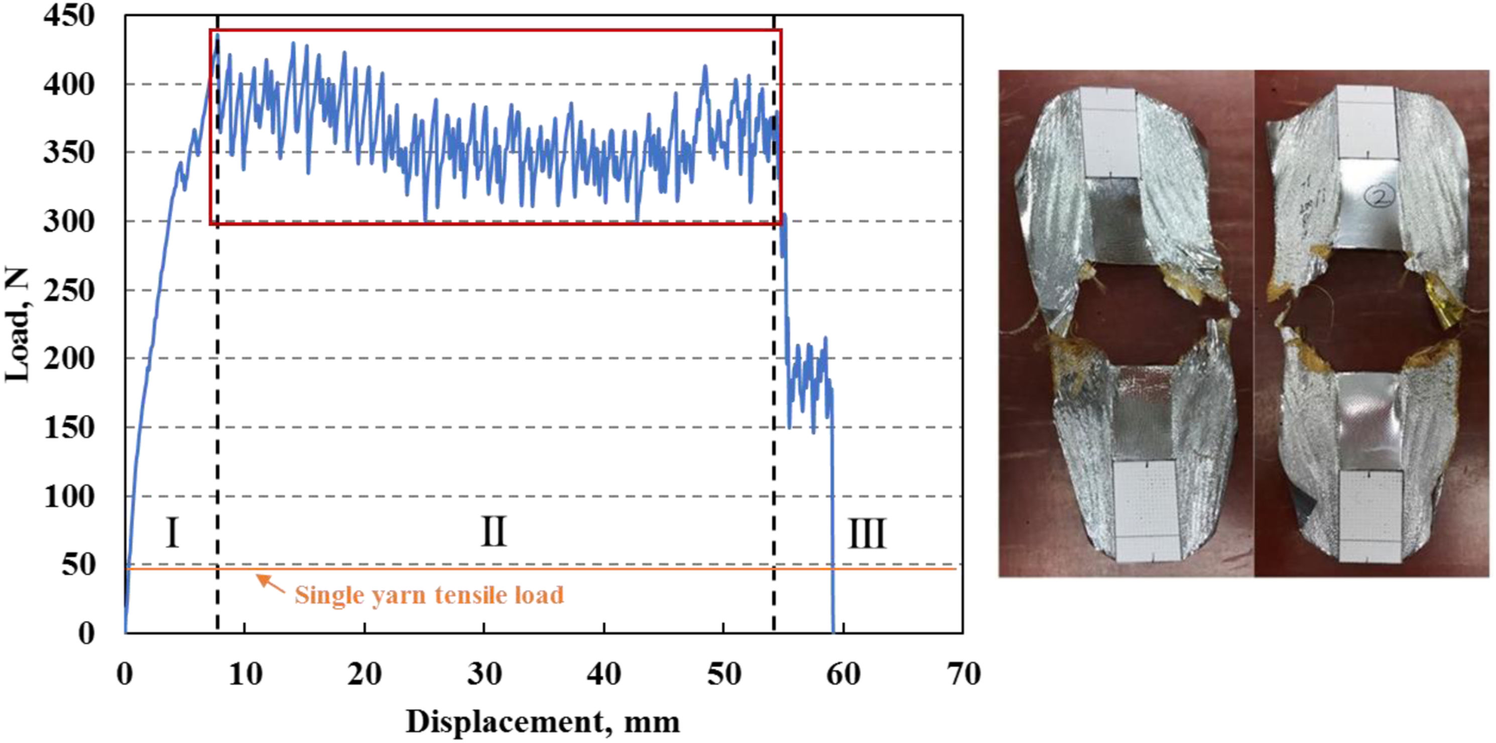
Figure 13 shows the fractured specimen after the test was completed. This type of specimen exhibited a more complicated mode of failure compared with the brutal failure. The failed specimens showed clear sign of yarns jamming together. The yarns in the loading direction break gradually and in groups with some short fringes protruding out. This indicates that the adhesion of the laminate is weaker compared with previous type of samples, and these yarns in the loading direction were broken under tension with minor pull-out. Films were cracked with some delamination observed around the tear failure boundary. This mode of failure is termed as “progressive failure.” Compared with the specimens of “brutal failure”, specimens of “progressive failure” exhibited higher load peaks before the tear propagation initiated. They were also stretched for much longer distance before failure to extend the tear propagation process and eventually slow down the tear failure. In this regard, laminate specimens with progressive failure have better tear resistant property. Nonetheless, specimens with brutal failure are evident to be stronger in laminate fabric-to-film bonding. Based on these findings, correlations between laminate tear behavior (mode and value) and adhesion properties can potentially be used as a new approach to evaluate the effect of lamination parameters on adhesion strength of laminate structures. Further research is required to modify and validate this concept.
Effects of lamination parameters on gas barrier property
GTR results of selective laminate samples.
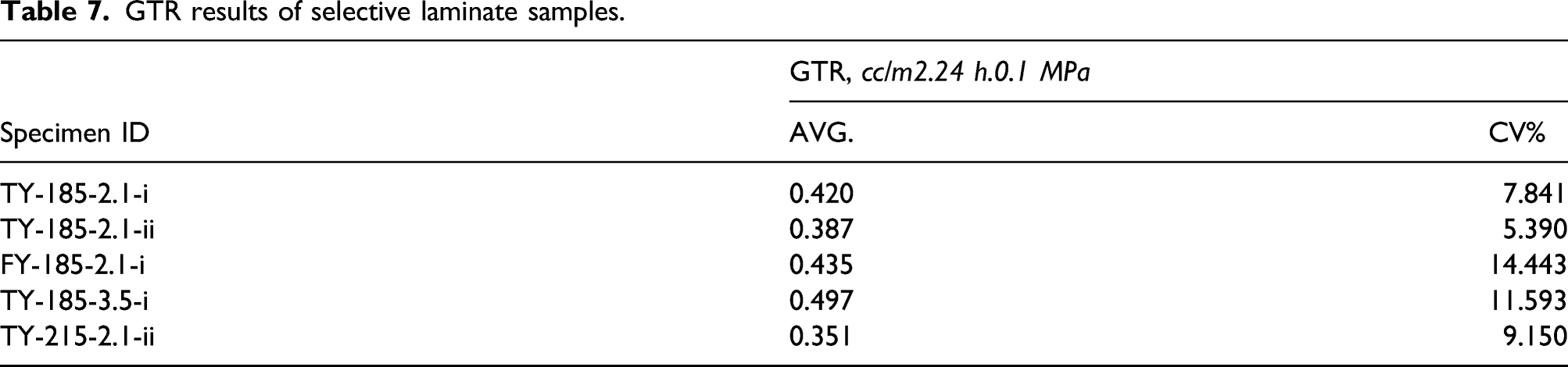
The helium permeation results of the selected laminate sample showed GTR value less than 1 cc/m
2
.24 h.0.1 MPa, which is two orders of magnitude lower than the upper limit of 80 cc/m2.24 h.0.1 MPa. These numbers are also significantly lower than the GTR values of Mylar® and Kapton® films which were already considered good gas barrier materials. The excellent helium barrier performance may be primarily attributed to the VDA coatings, which change the mode of gas permeation through polymer films significantly, because the areas covered with VDA coating become theoretically impermeable to the helium gas molecules. However, VDA coatings usually have defects such as pinholes, which become easy paths for gas molecules to rush through. So, the gas transmission performance will heavily depend on the size and number of these defects. In a laminated structure, the polymer adhesives may flow and fill the pinholes, replacing air in the pinholes with polymer which would improve the diffusion rate by orders of magnitude
30
. In this work, with semi-crystalline EVOH adhesive being used for lamination, its presence in the VDA pinholes further increases the difficulty for the helium molecules to get through. The crystalline region can potentially force tortuous paths of the gas molecules, increasing their chances of colliding into each other and therefore slow down the diffusion process. Additionally, multiple layers of VDA coatings can be even more effective delaying the transmission of the gas molecules by driving lateral diffusion between two VDA coatings, as defects are unlikely to be directly opposite to each other on two different coatings
30
. The main effects of temperature, dwell time, fabric types, and different replicas were plotted and compared in Figure 14. Effects of temperature, dwell time, and fabric type on the helium permeation of laminate.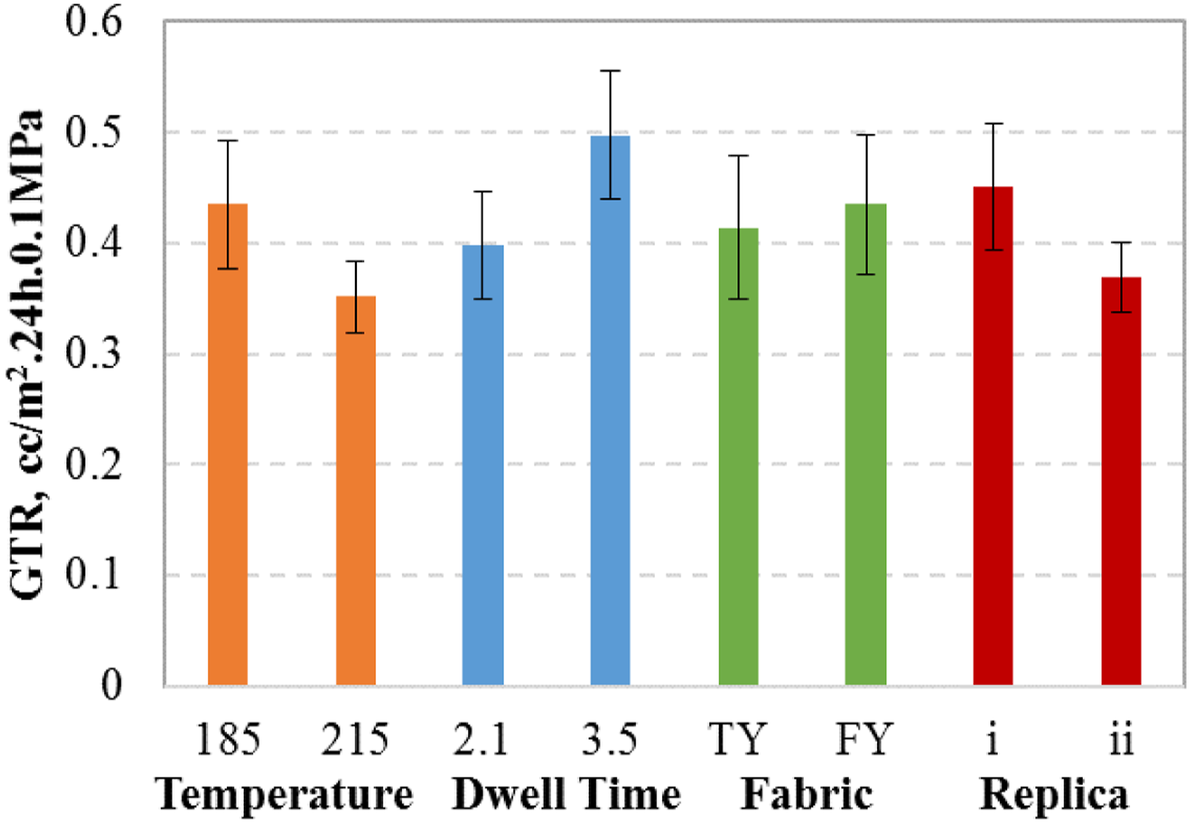
As observed in Figure 14, the difference of GTR value seems significant enough to confirm that dwell time of heating as well as lamination temperature do have an impact on the helium permeation property. However, with the GTR values being the same order of magnitude and extremely low, the results are practically very similar with one another concerning the helium barrier efficacy. Also, GTR values than 0.5 cc/m 2 .24 h.0.1 MPa cannot be distinguished from each other due to the margin of instrumental error and minor specimen variability. Therefore, it can be concluded that the helium permeation or transmission rate of the laminate material is consistently low regardless of the variables of the lamination or inherent variability of the materials.
Conclusions
In conclusion, this type of newly developed airship hull material is deemed to be a promising candidate to materialize the high-altitude airship, exhibiting the highest strength-to-weight ratio (633 kN.m/kg) among the existing lightweight (in the range of 100–150 gsm) laminate prototypes. The mechanical testing results showed that the tensile strength of the laminate is predominantly determined by the reinforcement woven fabric tensile strength. Laminate made with FY fabrics showed more balanced tensile properties (modulus and elongation at break) compared with TY fabrics. The peel test results showed that temperature have significant impact on the peel strength, while fabric types and dwell time do not have any impact. Increasing the lamination temperature from 185°C to 200°C improved the adhesion property, while increasing the temperature to 215°C did not further change peel strength. The statistical analysis of tear strength revealed that increasing the temperature from 185°C to 200°C significantly enhanced the tear strength. In addition, the analysis on failure modes and tear propagation curves suggests that laminate samples with progressive failure have better tear resistant property over those with brutal failure. Lastly, the extremely low helium permeation values of the laminates are mainly attributed to gas barrier polymer films in combination with multiple VDA coatings and semi-crystalline EVOH as adhesive, being two orders of magnitude lower than the upper limit of the acceptable helium permeability (80 cc/m 2 .24 h.0.1 MPa) for long-term fight duration. The lamination parameters and fabric types did not affect the gas barrier property. As long as the GTR value is below 1 cc/m2.24 h.0.1 MPa, the helium gas barrier efficacy is practically the same.
Footnotes
Declaration of conflicting interests
The author(s) declared no potential conflicts of interest with respect to the research, authorship, and/or publication of this article.
Funding
The author(s) received no financial support for the research, authorship, and/or publication of this article.