






Abstract
Fibre architecture of glass fibre (GF) reinforced polymer composites has a major impact on the mechanical properties for structural applications. In this study, a novel continuous glass fibre non-woven GF mat based on Spirograph art pattern is laid using a customized mechanical system. Spirograph-based continuous glass fibre non-woven (SNW) mat of different patterns was prepared and GF laminate epoxy composites were fabricated with the aim of achieving quasi-isotropic mechanical properties. The samples were cut to dimensions of test specimens from various identical locations symmetrically from a circular-shaped SNW composite laminates which were subjected to flexural, impact, shear and modified compression with anti-buckling tests. One particular SNW pattern composite laminate exhibited 40.82% better impact and 49.01% better shear resistance than commercial 0°/90° woven roving mat composite. The developed SNW laminate composite had quasi-isotropic fibre orientation and better mechanical properties without any stitching and interlacing as in case of woven fibre laminate composite.
Introduction
Glass fibre reinforced polymer (GFRP) composites are widely used in aerospace, automobile, marine, sports and construction. The orientation and architecture of glass fibre (GF) critically affect the mechanical properties of GFRP. The composites of 2D fibre mats of type [0°]S, [0°/90°/0°/90°/0°] and [90°]S demonstrated better shear strength due to in-plane isotropic behaviour compared to non-woven mat with random oriented fibre composites.1–3 Interlayer delamination and in-plane shear are two fundamental failure modes that occur in non-woven composites subjected to drop or hit by tools, debris, etc., that drastically reduce the loadbearing capacity. Impact resistance of GFRP is influenced by the stacking sequence of laminates inter-ply and intra-ply. Particularly, the angle ply [±45°]4S possesses better impact resistance in both longitudinal and transverse directions due to better inter-laminar shear strength.4–7 Furthermore, impact resistance of GFRP was reported to be enhanced by a hybrid of carbon/Kevlar/S-glass/E-glass, and evaluation by drop weight impact shown to cause minimal collapse and higher tensile/flexural strain due to the change of plane by wrap and weft undulations. Compared to 2D composites, 3D woven composites not only exhibited better in-plane shear represented by maximum load bearing and energy dissipation upon impact load, but also enhanced the impact resistance due to presence of Z-yarn that served as a superficial layer.3,8–12 Stitched fabric laminates had straight and non-crimped fibres with multiple fibre orientations also reported to improve strength and toughness of GFRP. However, inter-laminar shear strength of stitched laminates decreased with increase in stitch length and spacing due to damages occurred while stitching.13–15
Automated fibre placement and commingled fibre mats were recently developed for fabrication of composites, which allow the optimization of reinforcement lay-up and close control of process parameters such as roving diameter, fibre/matrix bonding, cooling rate, layer thickness, nozzle diameter, air gap, fibre feed rate and orientation. Also, laminate composite fabrication of fibres reinforced thermoplastic composites by fused deposition modelling reported to enhance the impact, shear and bending properties of composites. Yet, there are still some limitations exist such as interfacial bonding, porosity and anisotropic behaviour which would affect the load carrying capacity.16–23 A novel method preparation of electrospun mat based on Spirograph24,25 reported to enhance the mechanical properties due to fibre orientation in quasi-isotropic manner. The objective of this study is to evaluate the effect of Spirograph-based continuous GF non-woven (SNW) mat patterns on the mechanical properties of epoxy composite laminates and compare with 0°/90° woven roving mat (WRM) composites.
Experimental procedure
Materials
Properties of E-glass/epoxy UD composite laminate.

Note: UD: Unidirectional
Spirograph-based mechanical system and composite laminates
Spirograph-based mechanical system for laying non-woven continuous glass fibre mat in different patterns (hypotrochoidal curves) is shown in Figure 1 was designed and developed in house. It consists of meshing internal and external spur gears, pantograph link, DC motors and control panel. There are 105 teeth in inner gear and 72 teeth in external gear. The external gear revolves at 220 r/min through a connecting lever while meshing with inner gear. The fibre feeding system consists of a set of counter rotating rollers to maintain a constant speed and tension while laying the continuous fibre roving in a specific Spirograph pattern. Also, the speed of tow placement was proportionate to speed of external gear of Spirograph machine maintained at 220 r/min. The speed was optimized after initial trials, based on efficacy of Anabond® in binding fibre tows. (a) Spirograph-based mechanical system and (b) P1, P2, P3 and P4 positions.
Four positions, P1, P2, P3 and P4, as shown Figure 1(b) were selected in the external gear, which were offset from its centre by 50, 55, 60 and 65 mm, respectively, for fixing Pantograph linkage. A novel mechanical system for production of SNW mat with different patterns is possible (Figure 2) by selecting different points in the external gear. Laminae of circular shape with diameter 500 ± 10 mm was collected for 20 minutes in order to maintain equal wt. % as shown in Figure 3. The substrate for fibre placement was a coarse spaced wire intermesh to enable dripping of excess Anabond® and drying in ambient condition. The composite laminates produced using positions, P1, P2, P3 and P4, were referred as P1SNW, P2SNW, P3SNW and P4SNW, respectively. Spirograph patterns selected for SNW mat. Images of Spirograph pattern laid (a) intermediate state and (b) end of 20 min.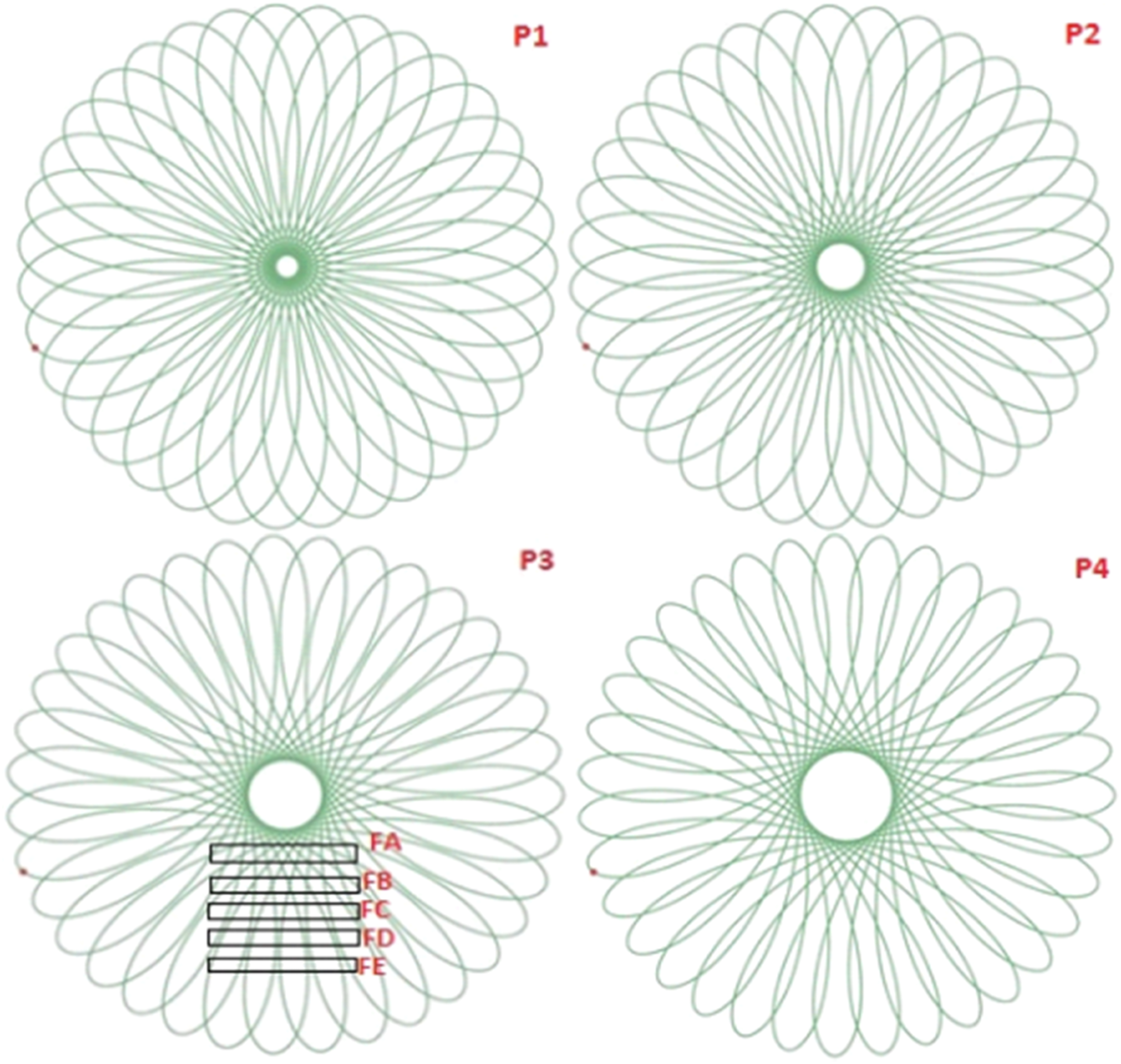

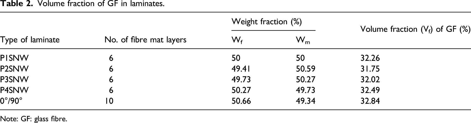
The volume fraction of fibre in SNW and 0°/90° WRM composite laminates was calculated by using rule of mixture equation (1), where Vf represents the volume fraction of fibres, Mf and Mm represent mass of fibres and matrix, respectively.
21
The value of density of glass fibre (ρf) and epoxy resin (ρm) was 2.52 g/cm3 and 1.2 g/cm3, respectively
Volume fraction of GF in laminates.
Note: GF: glass fibre.
Mechanical testing
Mechanical performance of fabricated SNW and WRM laminates was evaluated as per ASTM standards D790, D695 and D5379 such as three-point bending, modified compression with anti-buckling (CWAB) and Iosipescu shear tests1,4 in M/s. Jinan made WDW 50 model universal testing machine (UTM) using 1 kN and 50 kN load cells at cross head speed of 1 mm/min.26–30 The sample size for flexural test was 150 mm × 20 mm with a span length of 100 mm, CWAB test was 79.4 mm × 19 mm and Iosipescu test was 76 mm × 20 mm. In addition, Izod and drop weight impact tests were performed by 25 J capacity digital Izod - Charpy impact tester and M/s. CEAST made Fractovis drop weight impact tester, respectively, under ambient condition. The samples were cut from different locations of SNW mat composites by abrasive water jet machining (AWJM) in order to avoid delamination by conventional machining processes as shown in Figure 4. Images of specimens prepared (a) for flexural (FA, FB, FC, FD and FE) and impact tests (IA, IB, IC, ID and IE) (b) flexural (c) Izod impact test samples.
Samples of 20 numbers were prepared for 3-point bending and Izod impact tests are shown in Figure 4. For CWAB, 12 samples were prepared in dog bone shape and fixed with strain gauge to measure the end-to-end compression strain as shown in Figure 5(a) and (b). Test specimens prepared in SNW laminate for drop weight impact (DWI) and Iosipescu shear tests are shown in Figure 5 (d) and (e), respectively. Images of specimens prepared for (a) CWAB (b) CWAB with strain gauge and (c) CWAB fixture (insert fractured specimens) (d) DWI and (e) Iosipescu shear tests. Note: CWAB: compression with anti-buckling; WRM: woven roving mat.
The fixture and indenter used for Iosipescu shear and DWI tests are shown in Figure 6. M/s. CEAST made Fractovis drop weight impact tester at constant impact velocity of 3.192 m/s, hemispherical steel impactor mass of 3.926 kg and drop height of 519.487 mm were used to impact and investigate the low velocity impact properties of composite specimens.4,21 Images of test set up for (a) Iosipescu shear, (b) DWI test specimen holder and (c) hemispherical impactor. Note: DMI: drop weight impact.
To prevent specimens from multiple impacts, electromagnetic braking system in the impact tower captured the impactor after initial strike which can generate additional damage to the laminates. For both P3SNW and WRM composites, rectangular specimens of dimension 150 mm × 100 mm were clamped on four corners using pneumatic grippers which exhibited simply supported beam boundary condition as shown in Figure 6(b). The impact test parameters such as force, deformation, energy and velocity for SNW and WRM composites were obtained from data acquisition system.
Results and discussion
Flexural properties
The maximum load–displacement obtained from three-point bend test of various locations of P3SNW and 0°/90° WRM composites is shown in Figure 7(a). The flexural property of SNW mat composites shown to decrease with sample far away from the centre as the fibre content decreased in the order of FA>FB>FC>FD>FE as seen in Figures 2 and 4(a). Figure 7(b) shows that the FA sample of P3SNW laminate composite performed better than rest of composite laminates. Quasi-isotropic alignment of fibres (Figure 8) may be attributed to the quasi-isotropic stacking sequence.22,24 The angle between fibre intermeshing in FA location of P1, P2, P3 and P4 Spirograph art (Figure 8) was measured to be 78 ± 6.2°, 61.5 ± 5.7°, 44.8 ± 3° and 50.1 ± 2°, respectively. The performance of P3SNW was best among the four types of SNW laminate composites which was obviously due to close to quasi-isotropic (±45°). (a) Comparison of flexural results of various samples in P3SNW with 0°/90° WRM composites and (b) typical load versus displacement curves of flexural results of FA sample in different SNW laminate and 0°/90° WRM composites. Note: WRM: woven roving mat. Graphical representation of fibre orientation in FA samples for P1SNW, P2SNW, P3SNW and P4SNW single laminae.

It is observed that the maximum bending load of 525 N and 528 N withstood by P2SNW and P3SNW laminates for FA samples is higher than the other SNW laminates as well as 0°/90° WRM composites as shown in Figure 7(a) and (b). This shows that P3SNW composite exhibits better load-bearing property than 0°/90° WRM composites, due to planar isotropic fibre orientation, for equal volume fraction of GF. 17 Graphical representation of FA samples in P1, P2, P3 and P4 SNW laminae is shown in Figure 8 which indicated the fibre alignment angle and interlacing distance in the SNW mat. FA section in P3SNW possesses fibre arrangement angle near to ±45°.
WRM and P3SNW (FA)laminates were subjected to loss of Ignition (LOI) test, typical structure for stacked WRM and SNW fibre mat are shown in Figure 9 and fibre wt.% was found high in the former listed in Table 3. However, with the limitation of the fabrication process, WRM and SNW cannot be compared for the equal volume fraction of glass fibre as higher wt.% fibres concentrated at the centre of SNW laminate. Fibre orientation in (a) WRM and (b) P3SNW (FA) composites after burn out test. Note: WRM: woven roving mat. LOI results of P3SNW (FA) and WRM Composites. Note: WRM: woven roving mat.

Impact properties
Izod impact results of various SNW mat and 0°/90° WRM composite laminates are shown in Figure 10. The energy absorption of P1SNW and P4SNW composite is 2.87 J and 3.87 J, respectively. Compared to 0°/90° WRM, energy absorbed by SNW mat composites was better. Comparison of Izod impact results of various SNW laminates with 0°/90° WRM epoxy composites. Note: WRM: woven roving mat.
Also, P2SNW and P3SNW laminates exhibited better impact resistance than P1SNW and P4SNW composites. The maximum energy absorbed by P3SNW laminate composites is 5.27 J which is around 70.4% better than 0°/90° WRM composites. This indicated optimal concentration fibre and good bonding between fibre and matrix in SNW composites compared to WRM composites.
The energy absorption results obtained from DWI test for P3SNW and 0°/90° WRM composite laminates are shown in Figures 11 and 12, respectively. It is observed that the peak impact force absorbed by SNW composite laminates is high compared to 0°/90° WRM. P3SNW mat laminates restricted the damage propagation and withstood maximum impact load. Quasi-isotropic fibre orientations and spacing between interlacing fibre tows in P3SNW mat laminates were responsible for in-plane elastic behaviour resisting damage propagation and bearing high impact load than WRM mat laminate.20,31 DWI test results of P3SNW mat reinforced composite laminates. Note: DMI: drop weight impact. DWI test results of 0°/90° WRM composites. Note: DMI: drop weight impact: WRM: woven roving mat

It is also observed that a peak force in case of SNW composite was greater than WRM composites, due to in-plane elastic behaviour and also due to higher fibre content. Also, the shape of peak was smooth and symmetric in case of SNW laminate composite, whereas it was asymmetric and force decelerated in staggered manner, due to occurrence of perforation involving fibre breakage along longitudinal and transverse directions in WRM laminate composite and crack progress with least peak energy. 10 With due consideration of the fact that higher fibre content in SNW composite with six laminates and 10 laminates in WRM composites, the results show SNW laminate composites have better DWI performance.
The energy absorbed by the specimens under DWI occurs in three forms such as impact energy, absorbed energy and rebound energy. 32 The impact energy expended in damaging the matrix and intra-plies is represented by extend of displacement. 12 From impact energy versus time graphs of Figures 11 and 12, it is observed that after absorption of the impact energy, the rebound energy of 10.27–13.5 J was observed in case of P3SNW composites. But in case of 0°/90° WRM laminates, catastrophic failure occurred without rebound and least impact resistance 21 as observed by perforation unlike ellipsoidal damage in SNW laminate composite. The fibre structure of SNW with fibre tows with large interlacing distance and quasi-isotropic orientation was responsible for dent formation and display of better impact resistance than WRM mat laminate composite.
Figure 13. Impact force versus Deformation of (a) P3SNW and (b) 0°/90° WRM composites. Impact force versus Deformation of (a) P3SNW and (b) 0°/90° WRM composites.Note: WRM: woven roving mat.
Impact force versus deformation curves of SNW laminates reveal that P3SNW laminate can withstand peak force of 5216 N. From Figure 13(a) it is noticed that, oscillated ascending portion led to impact energy absorption and descending portion represented resistant to impact force which is in closed hysteresis cycle. This indicated that fibre orientations in SNW laminate restrict deformation by ductile fibre architecture. 9 In case of 0°/90° WRM, the maximum force of 2798 N absorbed by equal GF volume fraction composites as shown in Figure 13(b) where descending portion represented fragmentation of specimens with perforation which attributed to brittle behaviour of 0°/90° WRM composites. 33
The parabolic curves in Figure 14(a) indicate that no perforation occurred in any of the samples due to quasi-isotropic orientation in P3SNW composites. But in case of 0°/90° WRM composites, the velocity versus deformation curves revealed that the impactor had pierced without resistance12,34 as shown in Figure 14(b). From impact test results it is noticed that, under same impact velocity, force, drop height and impactor, energy absorption of composites is varied with fibre orientation which attributed to better impact resistance of material behaviour under sudden impact, besides higher fibre content in SNW composite. Velocity versus deformation of (a) P3SNW and (b) 0°/90° WRM composites. Note: WRM: woven roving mat.
Compression properties
Comparison of modified CWAB results of P3SNW and 0°/90° WRM composites.

Note: CWAB: compression with anti-buckling; WRM: woven roving mat.
The maximum compression load for six layers SNW laminate composite was less than 0°/90° WRM composite due to limitation of SNW mat which was decreasing GF content from centre to the periphery of the specimen as seen from Figure 2. The buckling of composites was constrained by anti-buckling plates under compression load as per ASTM D695. The actual load versus deflection plots for compression test of SNW and WRM mat laminate composite are shown in Figure 15, shows staggered slope in case of SNW mat composite due to interfacial fracture between matrix and laminae. The end-to-end compression load increased linearly for both P3SNW and WRM composites; however, WRM composites exhibited sudden drop in load unlike P3SNW composites with peak load lasting for a significant displacement. Also, it is observed that staggered slope in case of SNW mat composite is due to interfacial fracture between matrix and laminae. Though compression modulus of P3SNW composite with six layers of SNW laminate was low compared to 10 layers of 0°/90° WRM composites, resistance to compressive force and crushing was better with minimal deformation. Load versus displacement plots of compression anti-buckling test results of P3SNW and WRM composite specimens.
Shear properties
Iosipescu shear test results of P3SNW and 0°/90° WRM composites.

Note: WRM: woven roving mat.
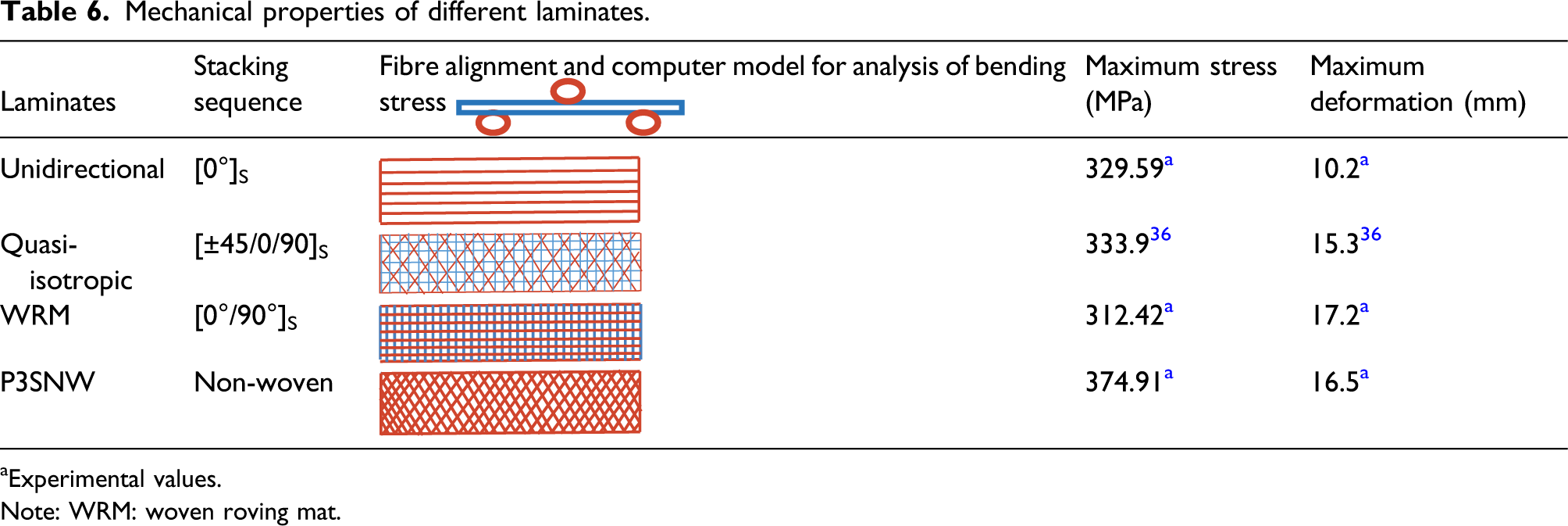
Mechanical properties of different laminates.

aExperimental values.
Note: WRM: woven roving mat.
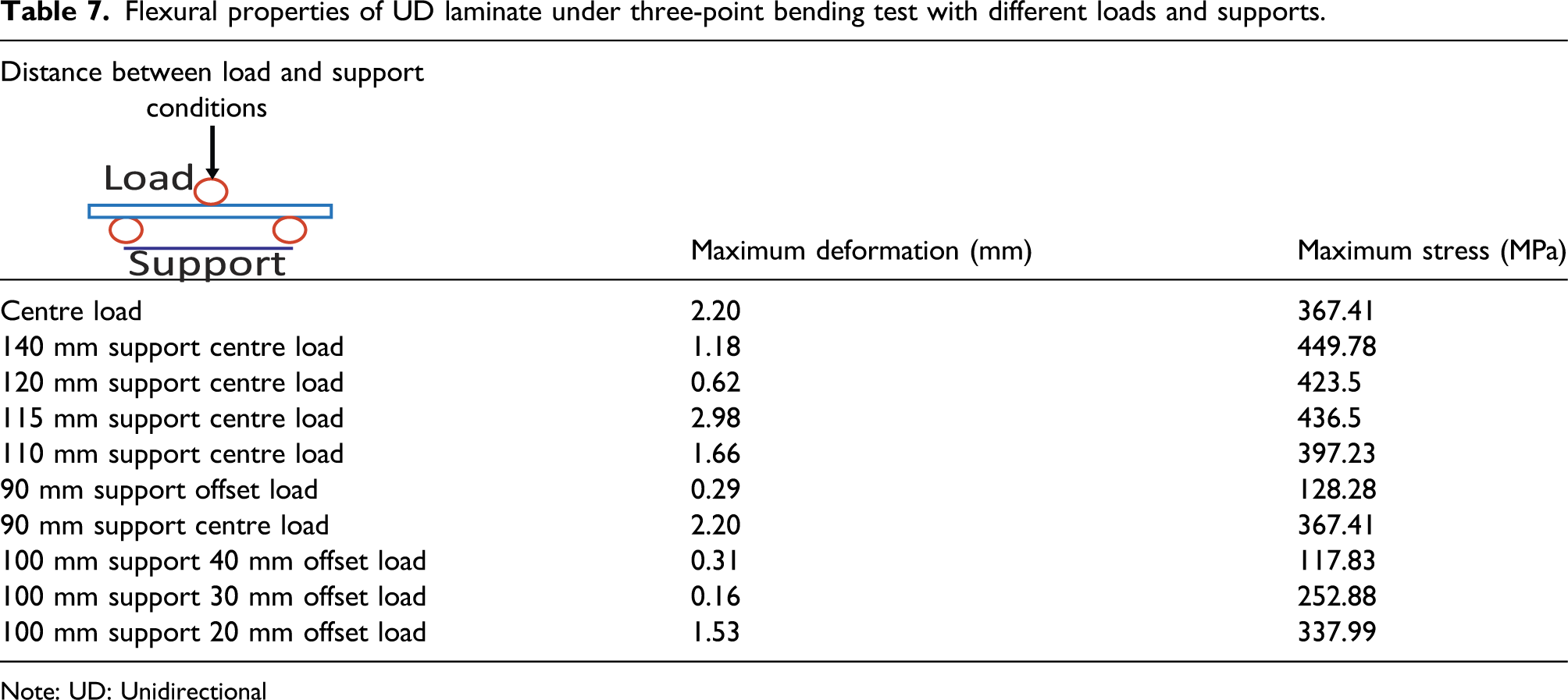
Flexural properties of UD laminate under three-point bending test with different loads and supports.

Note: UD: Unidirectional
The deformation and stress varied with the distance between load and supports. This might be the reason for better shear and impact properties of SNW composites compared to WRM composites, in which distance between inter-plies was low and fixed. The fibre alignments of SNW laminate at FA sample were also found to be around ±45°. Without any fibre–fibre interlacing, weaving, knitting, braiding or stitching, quasi-isotropic mechanical behaviour has been achieved in P3SNW composites.1,22
Fracture analysis of SNW composites
The images of fractured flexural samples (Figure 16(a)) revealed that P3SNW composite laminate FA sample exhibited interlayer delamination which was characteristic of enhanced inter-laminar shear strength14,25 and better load bearing property compared to 0°/90° WRM laminate. Fractured samples of (a) 3-point bending and (b) Izod impact test.
Fractured samples of Izod impact specimens shown in Figure 16(b) indicated that SNW laminate composites exhibited partial breakage compared to complete breakage of WRM sample. The better performance of SNW mat composites stems from in-plane shear and more energy absorption due to quasi-isotropic orientation of fibres and fibre length in the ply. 8 WRM mat with 0°/90° inter-ply fractured in brittle manner. The main parameters of impact energy absorption are fibre pull out, fracture and debonding of fibre from matrix.
The damage of samples after DWI test was revealed by visible impact defacement. The observed formation of dent and fibre pull out in SNW mat was the reason for higher energy absorption when compared to 0°/90° WRM, where delamination and fibre breakage observed in both the top and bottom surfaces as shown in Figure 17. Images of 0°/90° WRM and P3SNW composites fractured in DWI test. Note: DMI: drop weight impact: WRM: woven roving mat.
Interestingly, high energy absorption and less damage were observed in P3SNW composites than 0°/90° WRM which indicated that Spirograph-based fibre plies withstand better impact force. 9 Based on wrap and weft directions of fibres and these undulations did not prevent the impact force unlike Spirograph architecture. In case of P3SNW, partial breakage of outer layer fibre and apportioned the impact damage were due to Spirograph arrangement of GF. Compared to 0°/90° WRM composites, the damage area for P3SNW composites was less due to delamination and pull out of fibres. Ellipsoidal shape of matrix and fibre breakage were observed in both impacted and non-impacted sides of P3SNW due to high impact energy absorption. It was attributed to presence of symmetrically stacked P3SNW laminate with ±45° fibre orientation. 10
Fractured samples of 0°/90° WRM and P3SNW composite specimens after CWAB test indicated that both samples exhibited end-to-end failure under compression load which is shown in Figure 18. Failure of the specimens depends on the point where the specimen broke and delaminate resulting in a complete loss of load-bearing capability. From Figure 17(a), it is noticed that WRM composites failed near nose radius of the specimen with delamination and matrix crack observed barely. But at peak load, P3SNW composites exposed damaged at mid-section along the fibre directions as seen from Figure 17(b). This observed failure attributed to anisotropy nature of WRM composites compared to quasi-isotropic property of P3SNW composites. Images of fractured (a) 0°/90° WRM and (b) P3SNW composite specimens after CWAB test. Note: CWAB: compression with anti-buckling; WRM: woven roving mat.
Figure 19 represents the shear fracture of 0°/90° WRM and P3SNW composite laminates where delamination and fibre breakage are observed in 0°/90° WRM composites. It is observed that the cracks initiated at the V notched roots and propagated/deflected along the fibre direction.
21
Images of fractured (a) 0°/90° WRM and (b) P3SNW composite specimens after Iosipescu shear test. Note: WRM: woven roving mat.
The better shear performance of P3SNW mat reinforced composites was due to resistance to crack propagation by GF aligned in quasi-isotropic directions.7,12 Compared to GF orientation in 0°/90° WRM, fibre orientation and distribution were exaggerated in P3SNW mat in order to sustain flexural, shear, Izod and DWI loads. DWI and Iosipescu shear tests show better impact resistance and good shear behaviour of P3SNW mat than 0°/90° WRM composites.
In general, compared to angle-ply and cross-ply laminates, quasi-isotropic laminates had better impact and shear load behaviour. The performance of P3SNW was best among the four types of SNW laminate composites which was obviously due to close to quasi-isotropic (±45°). The fibre architecture in Spirograph pattern possesses quasi-isotropic orientation compared to any other non-woven laminate. The non-utilization of central portion of SNW laminate composite can be minimized with appropriate positioning of multiple laminae in non-centric manner.
Conclusions
A novel mechanical system was developed for manufacturing continuous glass fibre non-woven mat with distinct Spirograph pattern. Among the selected offset points, P3SNW composite laminate exhibited best flexural load-bearing property and Izod impact resistance. Izod impact, drop weight impact and Iosipescu shear tests shown that P3SNW laminate composites were the best due to quasi-isotropic fibre acclimatization. The fractured surfaces of P3SNW subjected to drop weight impact and shear tests confirmed enhanced load-bearing property with less matrix crack and fibre pull out and ellipsoidal-shaped damaged area. In case of 0°/90° WRM composite, delamination, fibre breakage and perforation of laminates were observed due to fibre alignments in longitudinal and transverse directions alone and shorter fibre length between plies. Further research is required to carry forward better impact, shear and compression resistance of SNW composites for structural application to endure impact and shear load.
Footnotes
Acknowledgements
The authors would like to acknowledge the funding of DST-SERB projects (EEQ/2016/000830, dated: 26-05-2017 and ECR/2016/002066, dated: 29-03-2017) for carrying out fabrication and testing of Spirograph-based non-woven fibre mat composites.
Declaration of conflicting interests
The author(s) declared no potential conflicts of interest with respect to the research, authorship, and/or publication of this article.
Funding
The author(s) received no financial support for the research, authorship, and/or publication of this article.
