
Abstract
The paper presents coated woven fabric roof structure analysis, from material characterisation to structural computations. The analysis aims to determine the cause of failure of the technical fabric roof structure in northern Poland. The behaviour of coated woven fabric material is investigated under uniaxial and biaxial tensile tests, tear tests and creep tests. The presented investigations may be considered an expert bearing capacity assessment of a roof structure covered by technical woven fabric. The paper starts with a literature survey on the investigations of coated woven fabrics. Next, laboratory test results are presented. The results indicated that the coated woven fabric behaviour under biaxial stress in the range of operational stresses can be satisfactorily reflected by its behaviour under uniaxial tensile stress. The specified long-term tensile strength covers about 35% of ultimate tensile strength. Structural analysis of the FEM numerical model is addressed too. Experimental studies and numerical calculations indicated that it was not the technical fabric, but errors in the design of its fastening that caused the failure. Finally, the conclusions of the study are shown. This paper provides scientists, engineers, and designers with a background for structural analysis of membrane structures made of coated woven fabric.
Keywords
Introduction
Coated woven fabrics, also known as architectural fabrics, are applied to form membrane hangings, pneumatic and other membrane structures. Novel types of coated woven fabric are still designed and manufactured. Investigations into the description of coated woven fabrics are conducted to provide a thorough understanding of coated fabric material performance under various conditions. The domain of laboratory tests covers uniaxial, biaxial, rheological, tear, etc., investigations. The literature concerning the subject of coated woven fabrics is extensive and referring to both engineering and scientific communities. Selected papers from the last 5 years are discussed in chronological order.
Hu et al. 1 reviewed studies on building performance, mechanical properties of membrane materials and structural behaviour of membrane buildings. Xu et al. 2 studied effects of boundary conditions, penetrator shape, yarn angle, puncture rate, weight percentage of fibre and coating on puncture resistance of architectural coated fabric. Chen et al. 3 presented nonlinear shear stiffness characteristics and deformation mechanisms of architectural non-crimp fabric under different stress states. They proposed a method to determine shear stiffness by means of shear stiffness-shear strain curves. Yang et al. 4 investigated mechanical properties of coated biaxial warp-knitted fabrics under off-axial tensile tests and biaxial tensile tests under five different load ratios Eun et al. 5 studied off-axis mechanical properties of polyvinyl chloride (PVC)-coated fabric with various viscosity PVC resins applying a tensile test, tear test and peel test. Guo et al. 6 analysed mechanical behaviour and energy dissipation of architectural membrane materials under multistage cyclic loading. They investigated deformation behaviour, energy dissipation and damage characteristics of four types of warp-knitted and woven polyvinyl chloride membrane materials by means of multistage cyclic loading experiments. Khaothong et al. 7 optimised welding parameters of polyester fabric coated with PVC, applying high-frequency welding technique, verified by confirmation experiments. Gao et al. 8 introduced the design of fabric material biaxial tensile tests in the material and experimental method, they proposed to optimise learning performance of the network model. Xie et al. 9 carried out a biaxial tensile test on coated fabric specimens between −33°C and 80°C, estimated the elastic modulus and Poisson’s ratio at different temperatures, given stress–strain relationships. Meng et al. 10 applied a hybrid deep neural network model to predict tear propagation of stratospheric airship envelope material, including stress field predictor and crack map predictor, considering temporal and spatial characteristics. Zadekhast and Asayesh 11 studied the effect of fabric structure and loading direction on creep behaviour of two bar warp-knitted fabrics. Özer et al. 12 investigated effectiveness of ED and DP as a potential phosphorus-containing flame retardant for polyethene terephthalate fabric to propose eco-friendly formulations.
Šveikauskaitė et al. 13 presented the development of artificial weathering test to investigate the variation of properties of architectural membranes and connections, incorporating climatic factors characteristic of continental climatic zone of mid-latitude in the ageing model. Schwaiger et al. 14 addressed tensile behaviour of flexible epoxy resin reinforced with knitted fabrics made of six different fibre materials, including bio-based and recycled petroleum-based fibres. Cai et al. 15 investigated mechanical deformation of woven polyvinyl chloride-coated film at different temperatures, applying proposed 1D model, improved Burgers model and a 2D model with orthotropic nonlinear model. Milošević et al. 16 showed the impact of support geometry on membrane stresses in barrel-vault-shaped membranes, they conducted a numerical experiment under variable parameters of support geometry to assess their impact on the maximum membrane stress under load. Uhlemann et al. 17 investigated the presence and extent of load history dependence in architectural woven glass fibre fabric material response; they assessed the impact of these effects on material stiffness parameters and structural computations. Bhadoria and Burela 18 derived analytically an asymptotically correct 2D nonlinear constitutive law for anisotropic coated fabrics employing variational asymptotic method. Tang et al. 19 investigated the impact of various braiding methods on the properties of class P membrane materials by uniaxial tensile tests. Arun and Meena 20 reviewed different applications of PVC, stated advantages and disadvantages of PVC application in each field. Wang and Ma 21 conducted uniaxial tension tests, biaxial tension tests and picture-frame shear tests on PET-uncoated/coated PVC fabrics, concluding that material coating yields superior elastic properties.
Jing et al. 22 pointed out key progress and perspectives in the field of 3D woven composite performance under impact loading, aimed at providing new insights into the design of new lightweight impact-resistant structural materials. Makhool and Balzani 23 designed loading protocols to thoroughly analyse inelastic behaviour of coated woven fabrics and proposed a visco-elastoplastic model for textile membranes at finite deformations. Zagubień et al. 24 focused on structures made of continuous tensioned membranes spanning a rope or bar network, with the largest uniform load-bearing area, they summarised the most commonly used yarn materials and coatings by basic strength parameters. Xu et al. 25 tested single-layer and double-layer welded seams of architectural coating fabrics under uniaxial tensile tests and analysed the effects of the off-axis angle, weld width and patch configuration on tensile strength, breaking extension and the failure mode. Qu et al. 26 addressed the impact of crack size on nonlinear mechanical response of coated fabrics by central tearing experiments, revealing intrinsic correlation law between tearing strength and crack length. Ultimately, it can be concluded that coated woven fabrics are still widely tested and investigated by engineers, researchers and scientists.
The Authors also published some papers where different aspects of mechanical testing of technical fabrics are presented e.g.27–29 Nevertheless, literature review indicates a lack of comprehensive studies of the mechanical properties of technical fabrics, based on several types of laboratory tests (e.g., uniaxial, biaxial, creep, and tear tests). An engineer cannot find complex mechanical description of a certain textile fabric in the technical data published by producer nor in scientific papers where usually results of one or two types of mechanical tests are published. There is still a need to supplement the knowledge on the behaviour of coated woven fabrics and failure of membrane structures. Here the Authors give wide mechanical characterization of the tested fabric enabling numerical analysis, calculation of safety factors and understating change of properties in different climatic conditions.
The research subject aims at membrane roof structure, where the origin of failure is investigated, from material characterisation to structural analysis. The investigations is focused an expert bearing capacity assessment of a roof structure covered by technical woven fabric. The paper starts with literature survey on coated woven fabrics. A series of laboratory tests (uniaxial and biaxial tensile tests, and creep tests) is carried out to cover the coated fabric behaviour of a built-in roof structure. The uniaxial tensile test is used to specify ultimate tensile strength of coated woven fabric under dry and wet conditions. The biaxial tensile test is carried out to reflect behaviour of coated fabric under biaxial stress state. The comparison of the biaxial tensile tests with uniaxial tensile tests can picture working character of coated woven fabric. The creep test is performed to specify the reduction factor necessary to determine the long-term tensile strength. Finally, the tear test indicated tear resistance of the coated woven fabric.
The aim of presented research was determination of reasons of failure of the textile roof of the warehouse in northern of Poland. Therefore, except of mechanical properties of used textile fabric determination the finite element analysis of the structure under different load cases has been executed. In the analysis most of experimental results were used to indicate the safety factor of used fabric. Finally, conclusions of the study which are useful of designers are drawn. Also the reasons of the roof failure are clearly indicated.
Membrane roof structure description
A cuboid building form is considered, its dimensions are 50.5 x 18.3 m in plan, featuring a cross-section resembling a double circular arc (see Figure 1). The building height at the roof edge is 3 m, the maximum height at the roof ridge is approximately 13.5 m. The roof surface is divided into 10 sections by glued wooden girders. The area between girders is covered by a membrane roof structure made of PVC-coated woven fabric with polyester yarns. In roof covering, the direction of the warp yarns aligns with the glued timber girders, i.e. the load-bearing structural elements. The weft direction of the fabric is perpendicular to the main structural girders. Each membrane section consists of two fabric panels joined along the weft thread direction (seam along warp direction). The lower edges of each panel are fixed around thin-walled steel profiles. According to the technical data specified by the manufacturer,
30
for the Sattler 684 POLYPLAN All-In-One FR coated woven fabric, the following parameters are given: polyester yarns as base fabric with a weave 1/1, weight 690 g/m2, tensile strength for warp and weft 260 daN/5 cm (52 kN/m) and 250 daN/5 cm (50 kN/m), respectively, and working temperatures ranging from −30°C to +70°C. Failure view of the roof made of coated woven fabrics.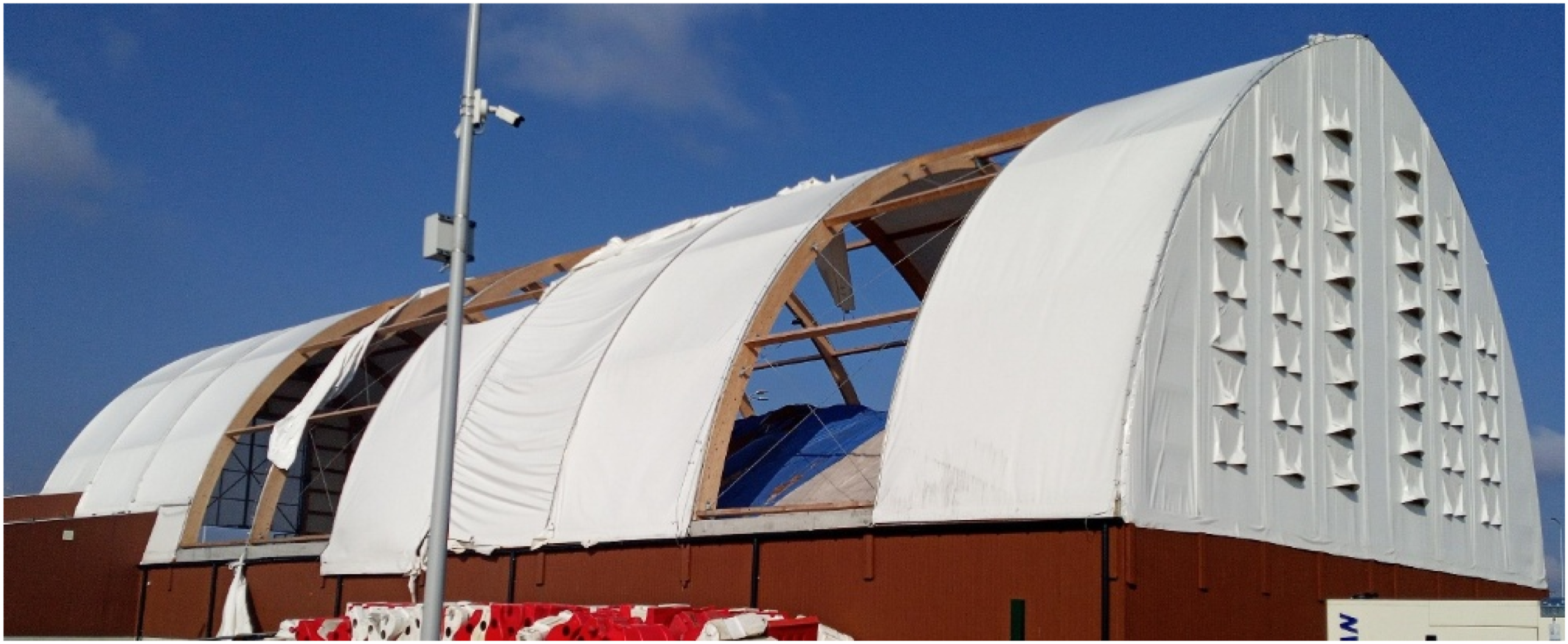
Engineering practice provides numerous interesting examples of technical solutions applied to membrane structures on building sites. In selected cases, the solutions proposed by designers are inappropriate and inconsistent with standard and technical requirements, as well as current scientific and technical knowledge. The membrane roof covering, made of coated woven fabric, was damaged after approximately 1 year of building operation. These facts indicated the necessity of acquiring an expert opinion on proper design of the membrane roof structure made of coated woven fabric and pointing out the causes of damage to the roof covering.
Laboratory tests of coated woven fabrics
The fabric specimens for laboratory testing were taken from the roof membrane during an on-site inspection of the building. To specify the properties of the coated woven fabric built into the roof structure, laboratory tests were performed. To describe the non-linear behaviour of the fabric, the uniaxial and biaxial tensile tests, tear tests and creep tests were carried out.
Uniaxial tensile tests
The tests are aimed at investigation of mechanical properties and their changes during operation under different humidity conditions, as well as comparison of the results obtained for two grip types. The uniaxial tensile tests were performed on a Zwick 020 mechanical testing machine with curved and flat grips under video extensometer control, which is based on the digital image correlation method. During the test, an optical extensometer of a base length of approximately 50 mm was applied. The specimens were applied (5 specimens in each sub-group) of a width of 50 ± 1 mm and the active length 200 ± 1 mm for flat grips (see Figure 2(a)) and 900 ± 1 mm for curved grips (see Figure 2(b)), respectively. Additionally, in flat grips tests, the specimens with the seams in the middle of the fabric along the weft direction were tested. The fabric on the roof had seams along the weft direction only (the only direction the panels were welded). Uniaxial laboratory tensile test stand with: (a) flat grips; (b) curved grips.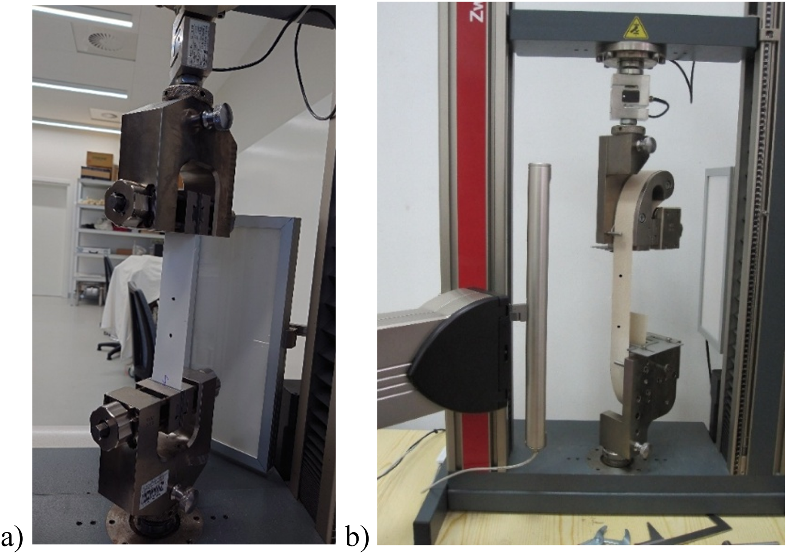
The tests were performed according to the ISO 1421 standard 31 guidelines for the strip method, with the displacement rate of the upper grip equal 100 mm/min. It should be noted that some types of coated woven fabrics showed significant difference between the ultimate tensile strength in the case of curved and flat grips, see e.g., 27 here the Polymar FR 8540-coated fabric reflected a 20% difference. Therefore, it was decided to perform a test with both grip types. According to tests with flat grips, the fabric samples were collected from panel No. 1 only, while in the tests with curved grips, fabric samples from two different fabric panels (panel No. 1 and panel No. (2) were applied. Two major groups of specimen treatment were conducted. The first group, referred to as “dry”, the fabric specimens were cut in the warp and weft directions from the roof fabric material left in room conditions for 2 weeks, next tested. In the second group, called “wet”, the samples were immersed in room temperature water for 2 weeks, next tested.
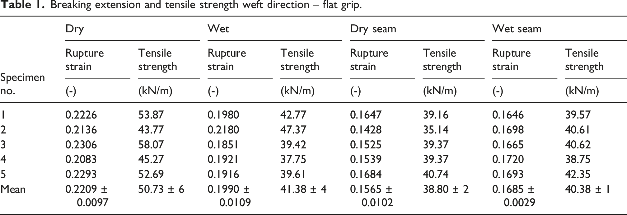
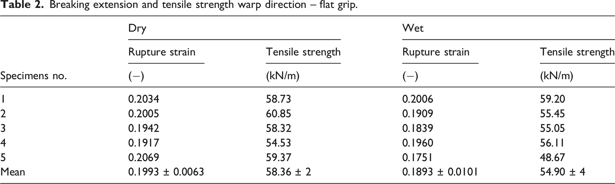
Generally, in each sub-group of tests, the results were coincident therefore, for clarity, in Figure 3(a) (weft) and Figure 3(b) (warp) the stress-strain curves are presented according to the representative specimens. The tensile strength for weft direction under uniaxial tensile tests with flat grips for dry fabric and wet specimens equals 50.73 ± 6 kN/m and 41.38 ± 4 kN/m, respectively (see Table 1). While the specimens with the seam are considered, the tensile strength in dry conditions is 38.80 ± 2 kN/m, in wet conditions the value is close to 40.38 ± 1 kN/m. In warp direction in dry conditions, the ultimate tensile strength is 58.36 ± 2 kN/m and for wet specimens 54.90 ± 4 kN/m (see Table 2). Statistical analysis of the results has performed to verify statistical significance of variations. Two groups (dry and wet) of specimens were investigated. Before the Student t-test performance the assumptions of normality (Shapiro-Wilk test) and variance equality (Brown-Forsythe test) were made. In the cases of both weft and warp directions, all tests were conducted positively. Selected stress-strain curves from uniaxial tensile tests: (a) weft direction; (b) warp direction. Breaking extension and tensile strength weft direction – flat grip. Breaking extension and tensile strength warp direction – flat grip.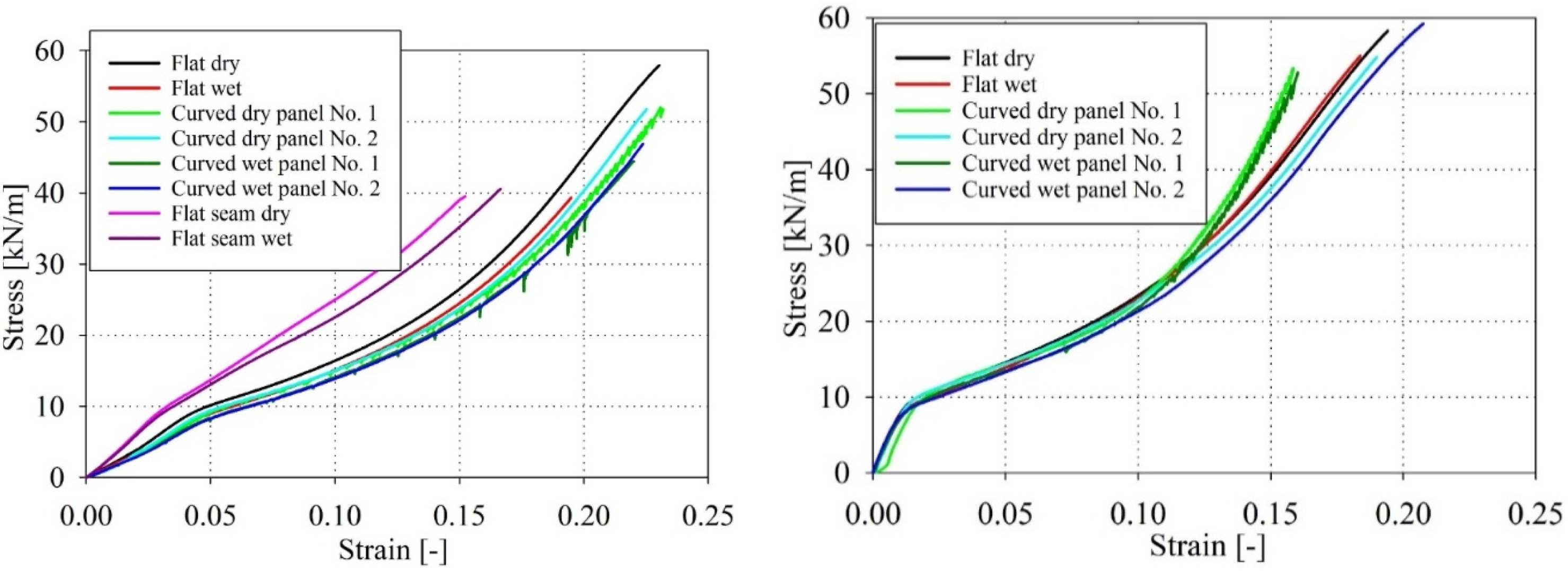
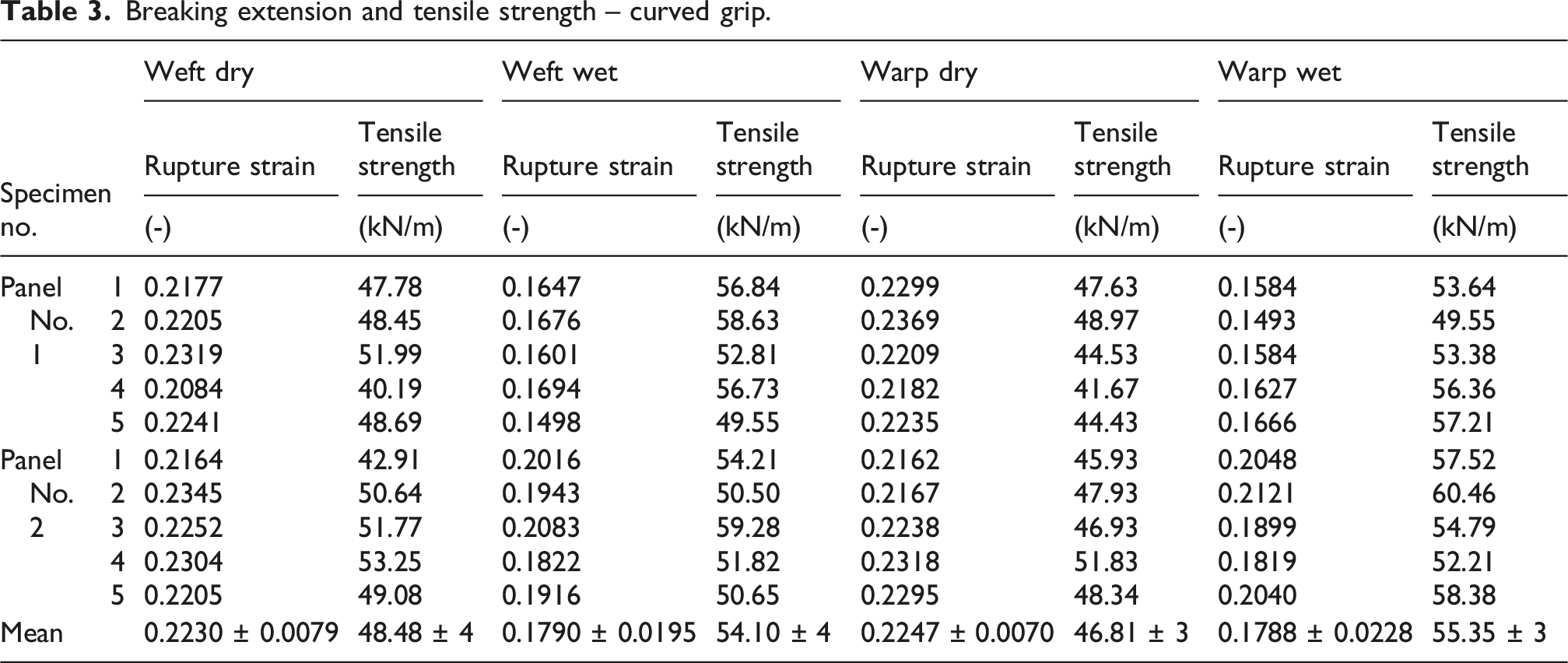
Breaking extension and tensile strength – curved grip.
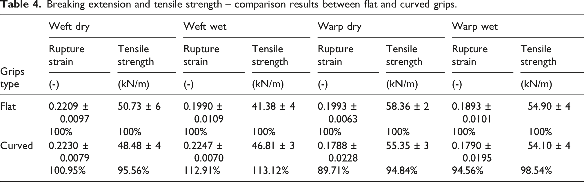
Breaking extension and tensile strength – comparison results between flat and curved grips.
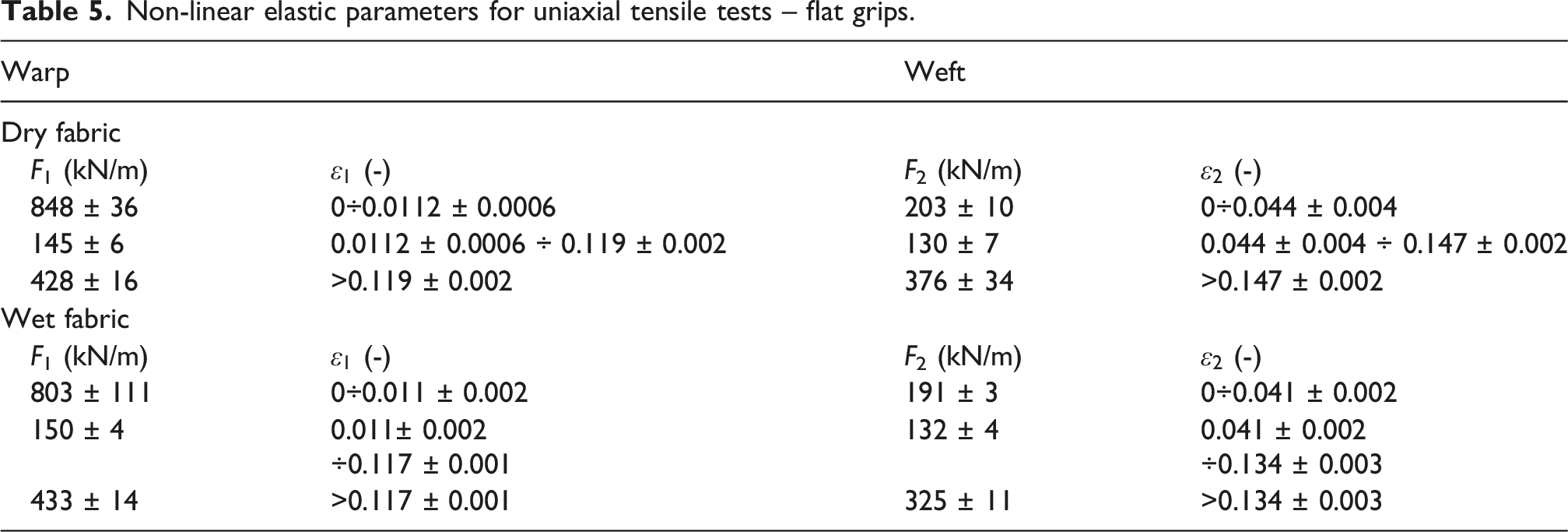
Non-linear elastic parameters for uniaxial tensile tests – flat grips.
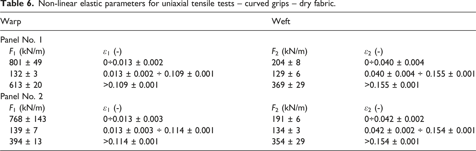
Non-linear elastic parameters for uniaxial tensile tests – curved grips – dry fabric.
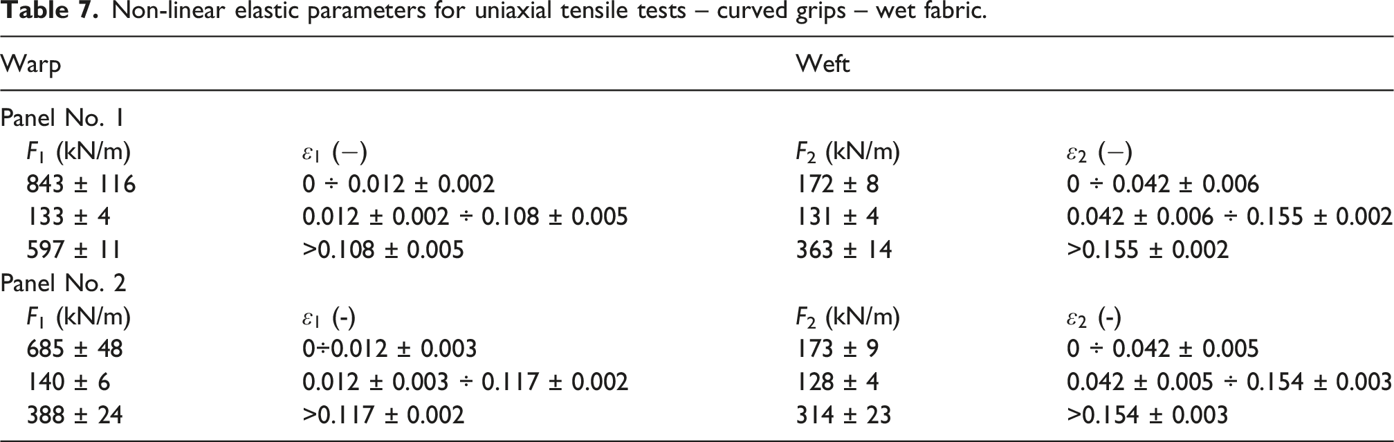
Non-linear elastic parameters for uniaxial tensile tests – curved grips – wet fabric.
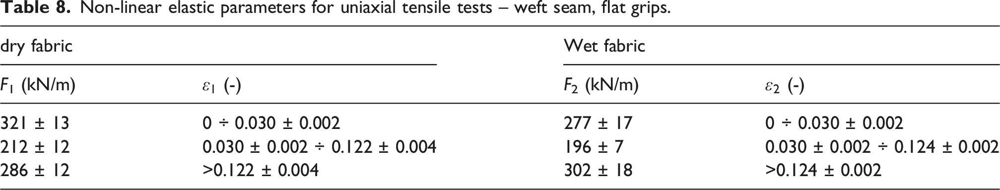
Non-linear elastic parameters for uniaxial tensile tests – weft seam, flat grips.
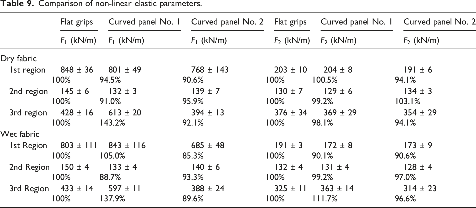
Comparison of non-linear elastic parameters.
Determination of tear resistance
Determination of tear resistance of the reference coated woven fabric was performed according to method B (trouser tear) guideline in the ISO 4674-1 standard
32
applying constant rate of the tear method, see Figure 4. The test variant presented in [71] for wide specimens was applied. The coated fabric specimens were 200 mmlong and Laboratory tear resistance tests: (a) fabric sample during test, (b) fabric sample before and after tear test.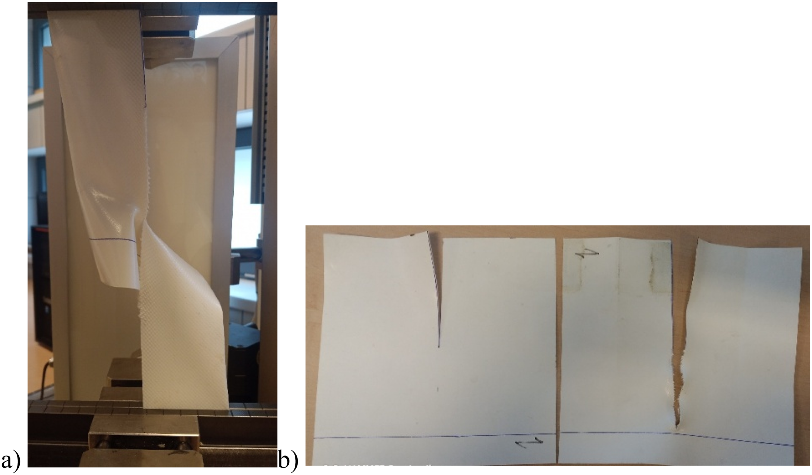
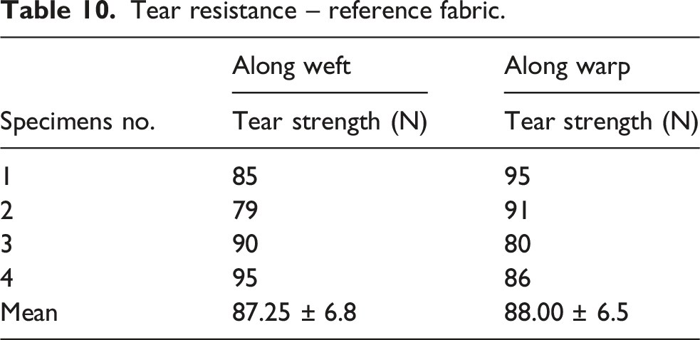
Tear resistance – reference fabric.
Biaxial tensile tests
Biaxial tensile tests were conducted on a Zwick BIAX 020 computer-operated strength-testing machine with four cross-shaped arms equipped with flat grips, see Figure 5. The optical extensometer (video extensometer), which provided non-contact, high-resolution measurements of deformations, was suspended over the cross-shaped fabric specimen with a gauge length of approximately 50 mm in both directions. The gauge marks were automatically recognised, displacement of the marks from image to image was converted to extension and transmitted to the measurement and control electronics. The cross-shaped fabric specimens display an arm width of 100 mm and the grip separation is 300 mm. Biaxial tensile tests were conducted with five different constant stress ratios, σ1:σ2, equal 1:4, 1:2, 1:1, 2:1, and 4:1 (here σ1 and σ2 represent the stresses in the warp and weft directions, respectively). The load rates for stress ratios are specified in Table 11. Biaxial tensile test stand. Load rate for different load ratios and the value of the stress at the specimens breaking point.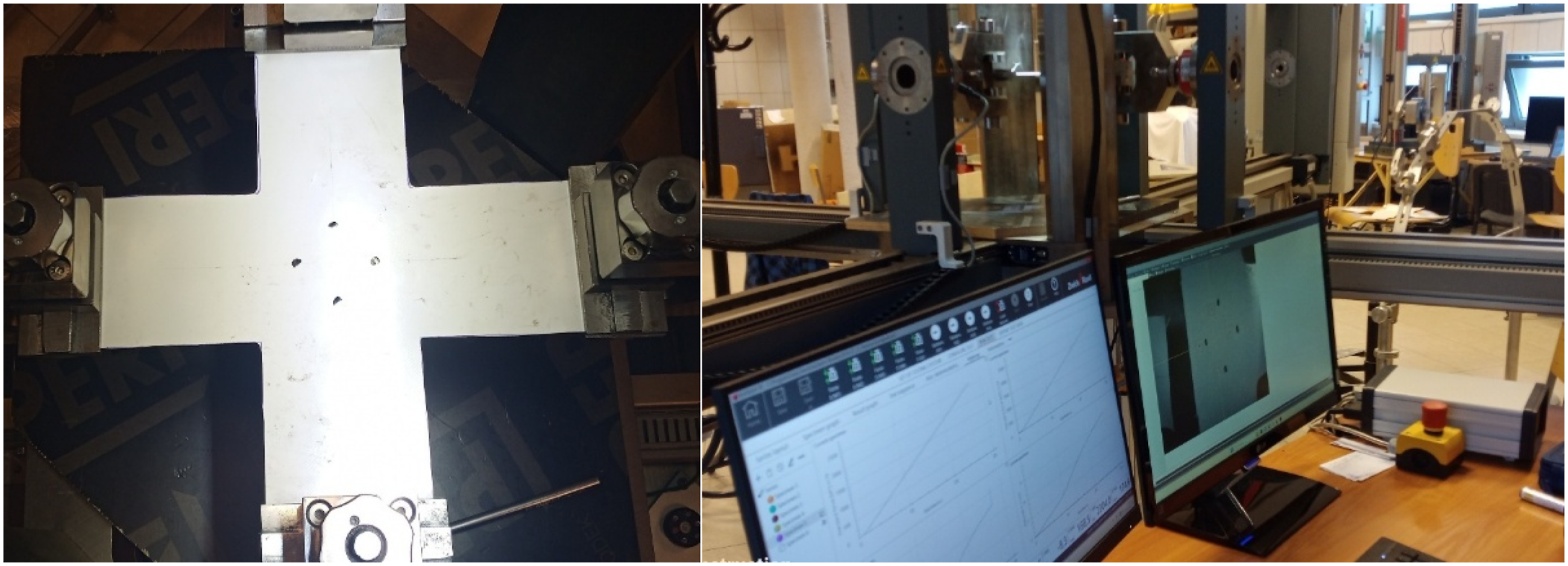
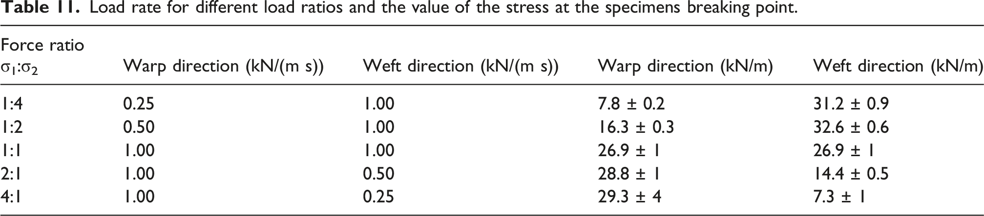
Stress-strain curves under biaxial tensile tests, compared to uniaxial tensile test results, are presented in Figure 6. The performance of coated fabrics is comparable to their behaviour under a uniaxial stress state. Only in the case of warp directions under 1:4 and 1:2 load ratios, the results differ from those under uniaxial stress. In this case the weft threads are highly loaded and straightened, so the warp threads become folded. After this sequence, the warp and weft threads are stretched, the negative strain in the warp direction switches to positive strain. This coated woven fabric behaviour was also recorded in,27,28 here other types of PVC-coated fabrics were investigated. It can be shown that in the operating stress range, the behaviour of coated fabric under a biaxial stress state can be thoroughly covered by a uniaxial tensile stress case. The stresses at the specimens breaking points are collected in Table 11. Biaxial laboratory test results: (a) 1:1, 4:1 and 2:1 stress ratios, (b) 1:1, 1:4 and 1:2 stress ratios.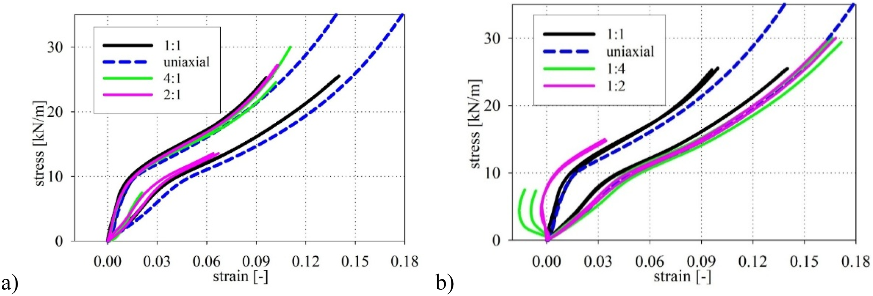
Creep tests
The 14-day creep tests were conducted to determine the long-term mechanical properties. Such tests are necessary to obtain the long-term tensile strength (LTS) as shown in.29,34 The creep stand presented in Figure 7 consists of two steel frames, each equipped with 10 posts, individual coated fabric specimens can be tested here. The specimens were subjected to tension at three levels of stress, equal 25%, 45%, and 65% of the ultimate tensile strength specified for flat grips (50.73 kN/m for weft and 58.36 kN/m for warp, see Table 4). The strain was measured and recorded by a computer-operated system. The specimens subjected to creep test showed a width of 50 ± 1 mm and a base length (between grips) of approximately 100 mm. Creep test stand – a general view.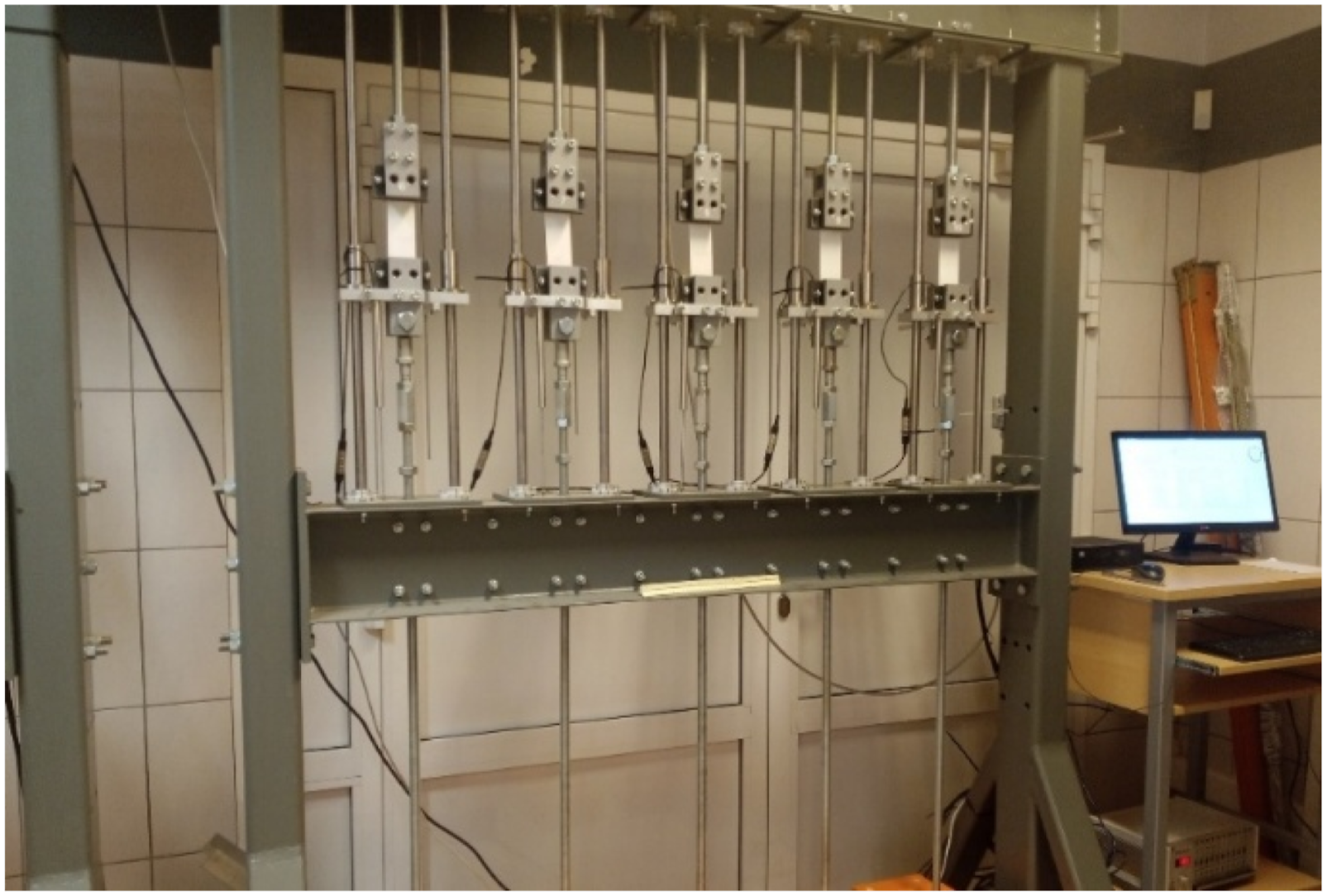
The creep test results for each load level are reflected by strain development in time curves (the engineering strain, the base length between grips), see Figure 8. The behaviour of the coated woven fabric during creep tests showed a high strain dispersion in time domain. The fabric specimens were taken from different parts of the membrane roof, the obtained results are reflected in their various mechanical properties. Comparison of the strain-time curves for (a) the weft direction; (b) the warp direction.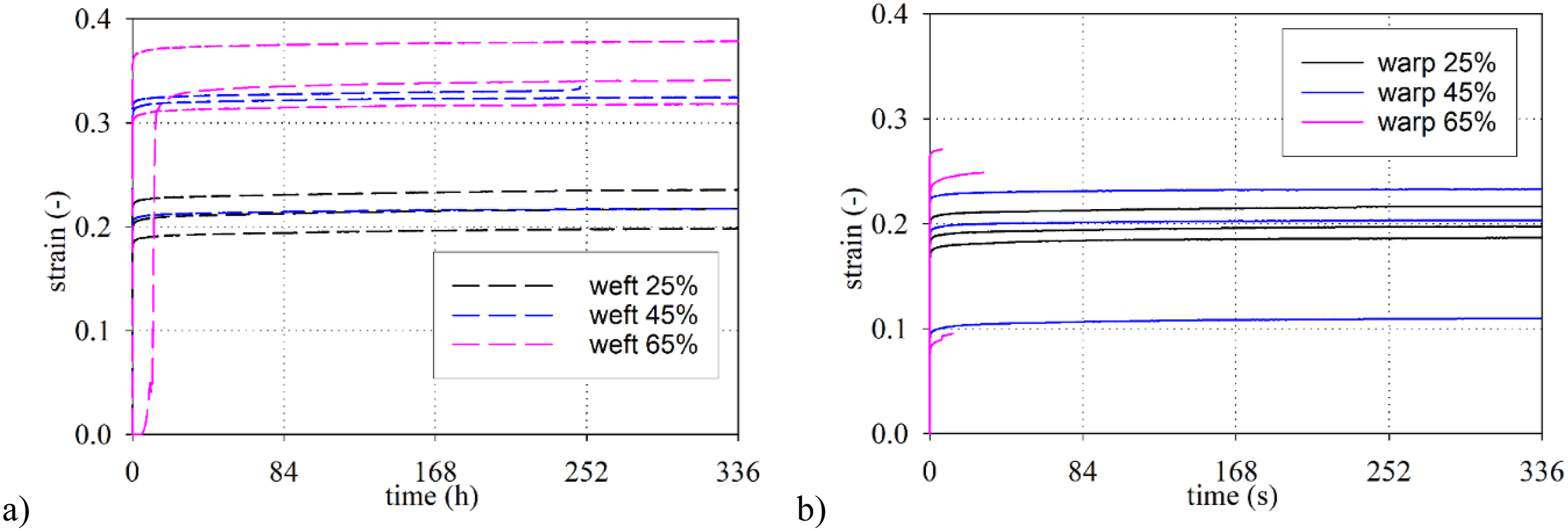
In the case of the weft direction, one of the tested specimens broke off under the loading equal 45% UTS. All tested warp specimens failed the tests in the test with stresses of 65% of the UTS. In this case, the fabric warp samples broke off after a few days of loading. It can be assumed that specimens showing up to about 45% of the ultimate loading (45% RUTS) fulfil the 14-day tensile tests for the warp direction ((1/0.45) = 2.22), see.29,34 Therefore, the factor γ1 = 2.22 (45% RUTS ⇒ 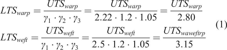
Next, considering the minimum UTS values specified in warp and weft directions (see Table 4), the long-term tensile strength can be determined, as follows: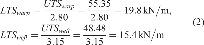
The specified long-term tensile strength covers about 35% of ultimate tensile strength. It means that investigated coated woven fabric can safely carry long-term loads to indicated limits. Beyond these limits, the uncontrolled failure of technical fabric can occur.
The FEM-based load capacity assessment
The 3D FEM model
A three-dimensional finite element model (3D FEM) is built of a roof structure made of the coated woven fabrics see Figure 9(a). The FEM numerical analysis employs the HEXAGON Marc Mentat system. The inspection, which revealed site damage to the roof covering, it indicates, that the supporting structure of the glued timber girders do not directly contribute to the damage to the roof covering. Therefore, computations are focused on the covering made of coated woven fabric. Individual segments of the covering are attached to the girders (their stiffness is significant, compared to the membrane stiffness) and prevent the covering from sliding in the perpendicular direction. Therefore, it is possible to analyse each span of the covering individually. The middle span is selected as representative for the roof covering performance and identification of the possible causes of roof damage. 3D FEM model of the roof structure (a) basic dimensions; (b) finite element mesh.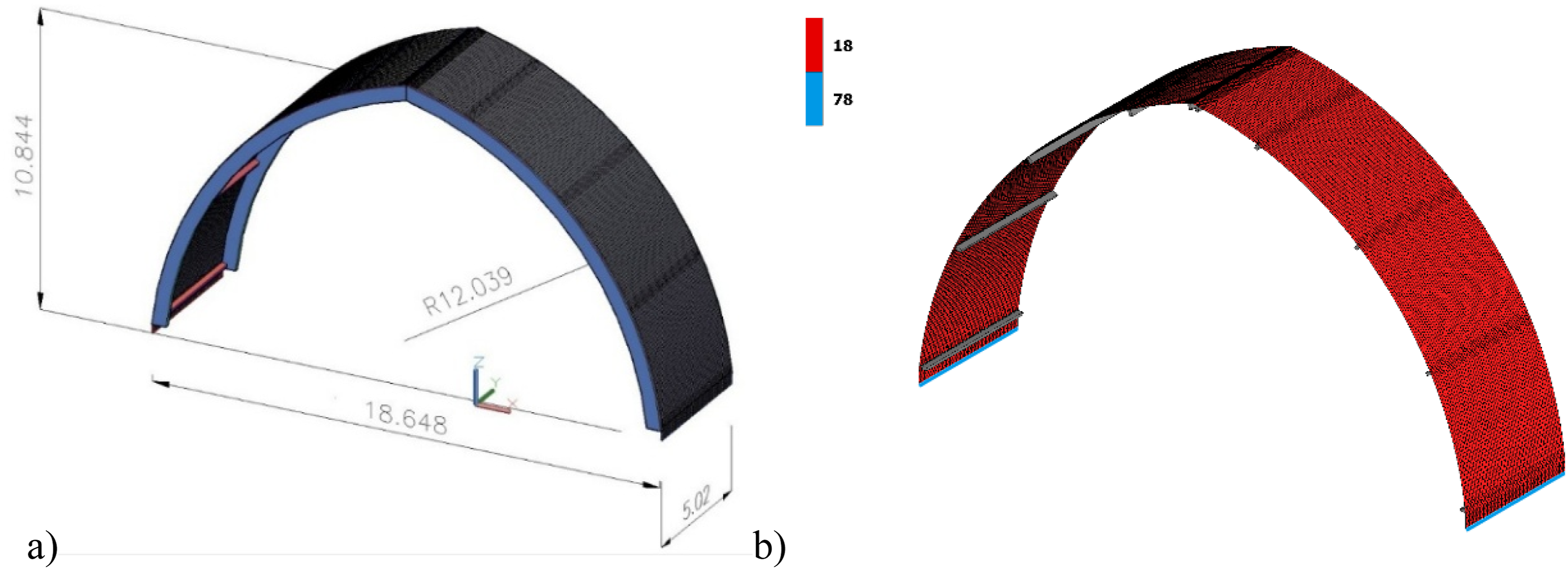
The 3D FEM model contains coated woven fabric material, modelled by four-node membrane elements (No. 18) and wood purlins with dimensions of 20 x 10 cm, modelled as solids, in contact with the coated fabric may be during deformation caused by loads. The glued timber girders, due to the method of fastening the edge keders of the fabric, are modelled by supports. It is assumed that the fabric is supported in both directions, perpendicular to the girder and parallel to the warehouse axis. The edge beams used to tension the fabric, made of rectangular steel profiles, are modelled by thin-walled beam elements (No.78). On the lower corners of the analysed part of the covering, the fabric and beams are not able to move in both X and Y directions (due to the warehouse wall), a displacement may be applied in the Z direction, to simulate the covering tensioning. The membrane finite element mesh was refined to better model the fabric-purlin contact in the regions of expected fabric-purlin contact during loading.
For the coated woven fabric, an orthotropic constitutive model is adopted with the longitudinal stiffnesses for warp direction F1 and weft direction F2 specified in Table 8 for flat grips. In rectangular steel edge beams, Young’s modulus equals 2e11 N/m2 (200 GPa), Poisson’s ratio is 0.3. The coefficient of friction of purlin beams fabric contact is 0.2. The model of the covering segment includes 18,100 membrane elements and 100 beam elements, shown in Figure 9(b).
Loads
Numerical analysis is performed in geometrically nonlinear domain, the order of load application is crucial. To ensure numerical stability of the model, it is assumed that during the assembly, the fabric is tensioned with a force of 0.25 kN/m in both directions. Next, in the first load case, dead weight and tension caused by displacement of end points of the edge beams are applied simultaneously. Preliminary calculations read that in the case of initial tension in the weft direction less than 0.25 kN/m, during the wind action the fabric is folded in this direction. Similarly in the warp direction, to prevent the fabric from folding under the action of the wind, it is necessary to pre-tension it to 0.25 kN/m, next move the tension beam at least 15 cm downwards.
The second load case is the wind action: along the roof (called suction) and across the roof axis in two variants (called pressure) according to PN-EN 1991-1-4
35
. The wind acts on membrane elements. The suction wind magnitude is assumed −1.47 kN/m2, see Figure 10(a). In the case of pressure, the roof covering is divided into four zones of equal length, according to PN-EN 1991-1-4
35
creating two variants of pressure computations, see Figure 10(b) and (c). Wind load cases: (a) wind suction, (b) wind pressure (variant 1), (c) wind pressure (variant 2).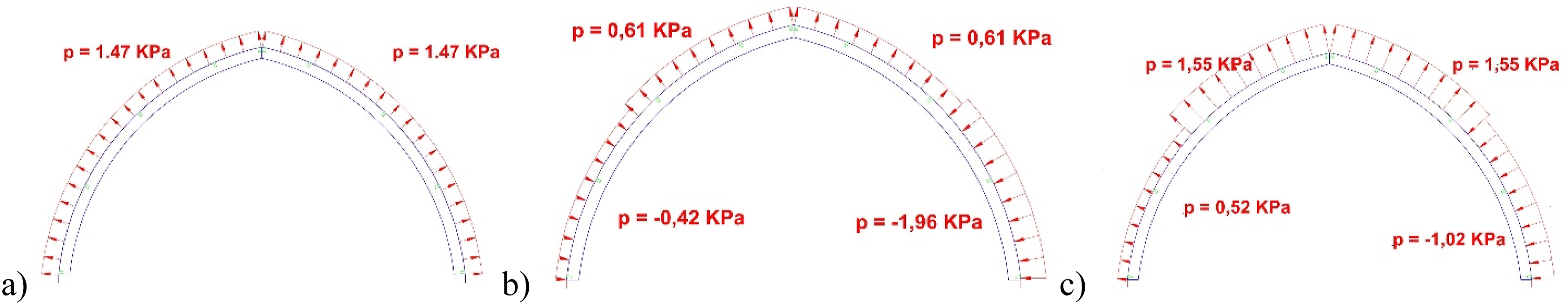
Since damage of the roof covering is not caused by direct action of snow, the latter is excluded from load capacity and damage assessment. The analysis of the results takes into account the condition of roof covering after its initial tension, considering its own weight. In the case of wind, displacements are analysed when the wind reaches its characteristic value, stresses are analysed when the wind takes its design value; here, the load factor is 1.5.
Structural analysis results
Three major causes of numerical calculations are investigated. The roof structure is loaded by self-weight and pre-tension forces only, followed by wind pressure or suction.
Calculation results for the case of self-weight and pre-tension forces
Due to insufficient data on the method of installing the coated woven roof cover and its tensioning, numerical computations are conducted in several variants, assuming various fabric tensile forces in the weft direction. If the tension in the weft direction is less than 0.1 kN/m, it is not possible to tension the fabric in both directions by moving the edge beams. If the weft tension is achieved in the range of 0.1÷0.2 kN/m, the cover may be tensioned on both sides by moving the edge beams by approximately 10-15 cm. However, in this variant, the standard effect of wind on the cover makes it loosen either in the weft or the warp directions (the second load case). The correct fabric tension, makes it necessary to tension it to a force of at least 0.25 kN/m in the weft direction, next to carry out the extension by a tensioning beam, approximately 15 cm downwards. When the beam is shifted by approximately 8 cm the reaction forces at the ends of the tension beams, are approximately equal to 2.07 kN, it causes yield of the cross-section of the tension beam over the design stress state.
Due to extension, the displacements indicate that, the fabric is pressed against the purlins. In the case of longer covering performence it can make it rub in these locations. Additionally, it can be stated that the covering deformation in the edge beam region is uneven, due to low stiffness. When the extreme points of the beams move by 15 cm, its centre moves by 6.5 cm only (see Figure 11), at the stage of fabric extension in warp direction results in significant deformation of the tension beams. Vertical displacements under dead loading [m].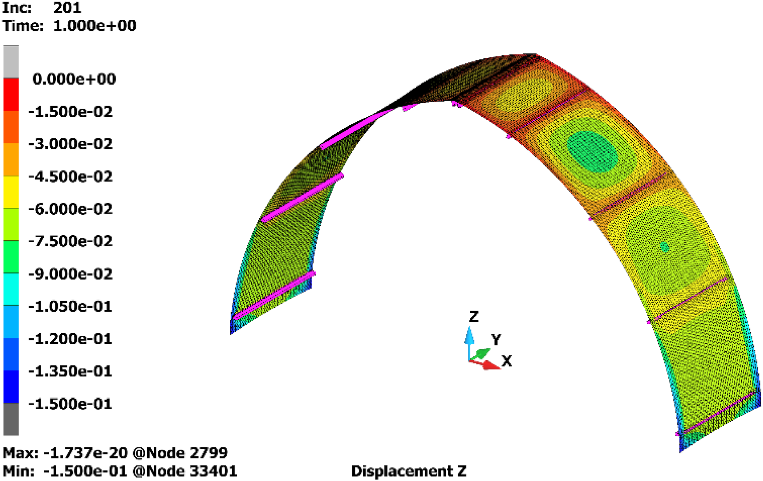
The fabric stresses in the weft direction are approx. 0.3÷0.5 kN/m, in the warp direction they are approx. 0.1÷0.5 kN/m, see Figure 12(a) and (b). However, a difference in stresses can be observed in the lower part of the keder strips, here the stresses due to warp extension increase to approx. 2.0 kN/m. Additionally, the lowest purlin causes a significant stress concentration in the lowest part of the fabric (see Figure 12(b)), where local stresses in the warp direction reach 13 kN/m. The latter is a value close to the long-term tensile strength. In the long-term operation process of the covering, it may result in fabric damage in this zone. Stresses in the fabric under dead loading: (a) weft; (b) warp [1 kN/m = 106].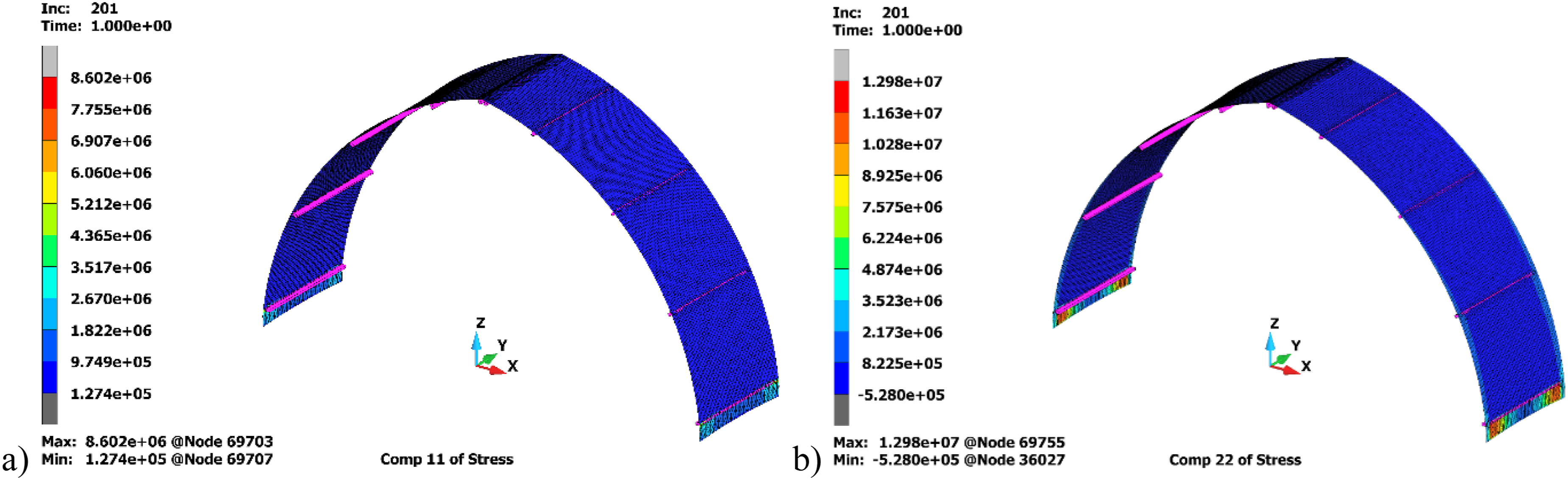
Calculation results for the wind suction load case
Wind suction causes the fabric to detach from the purlin (in this case vertical displacements reach about 46 cm, see Figure 13). The calculations show that the wind effects caused the coated fabric to hit the purlin beams. Vertical displacements for suction loading [m].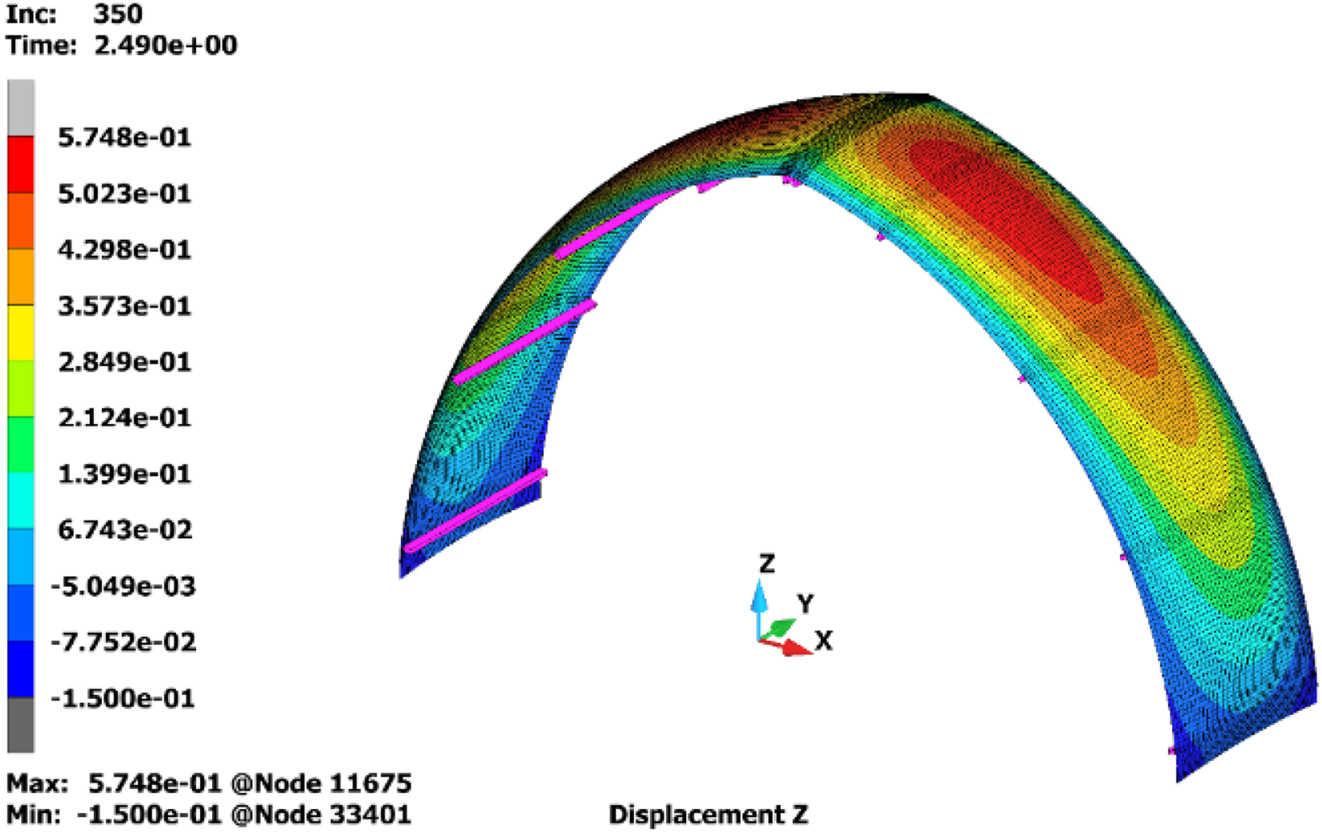
This effect causes an accelerated process of fabric surface damage and its local failure. The effect of wind suction of the assumed magnitude causes fabric tension in the weft direction up to 7.3 kN/m (see Figure 14(a)), while in the warp direction, the tensions in the fabric reach 10.0 kN/m, see Figure 14(b). Stresses in the fabric for suction loading (a) weft; (b) warp [1 kN/m = 106].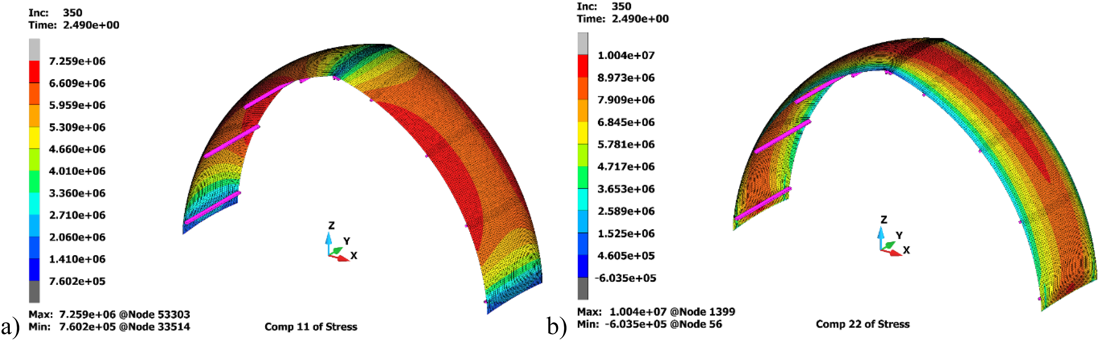
The impact of the roof fabric at the edge beam indicated loads about 4 kN/m at the beam ends and 9 kN/m in the midspan. These values significantly exceed load-bearing capacity of tension beams.
Calculation results for the wind pressure load cases
Comparing two pressure variants (compare Figure 15(a) and (b)), it can be stated that variant 2 is disadvantageous for the fabric roof covering. It causes higher displacements and higher stresses in the coated woven fabric. The transverse effect of wind pressure on the roof covering causes its vertical displacements from approximately 45 cm in the highest pressure are in the tear-off zone up to 35 cm, see Figure 15(b). Displacements in the pressure variant 1 show the order of the extension, see Figure 15(a). Similarly to the case of suction, the dynamic effect of this load make the coated fabric hit the purlins, which results in its accelerated surface destruction. Vertical displacements for the case of pressure load: (a) variant 1; (b) variant 2 [m].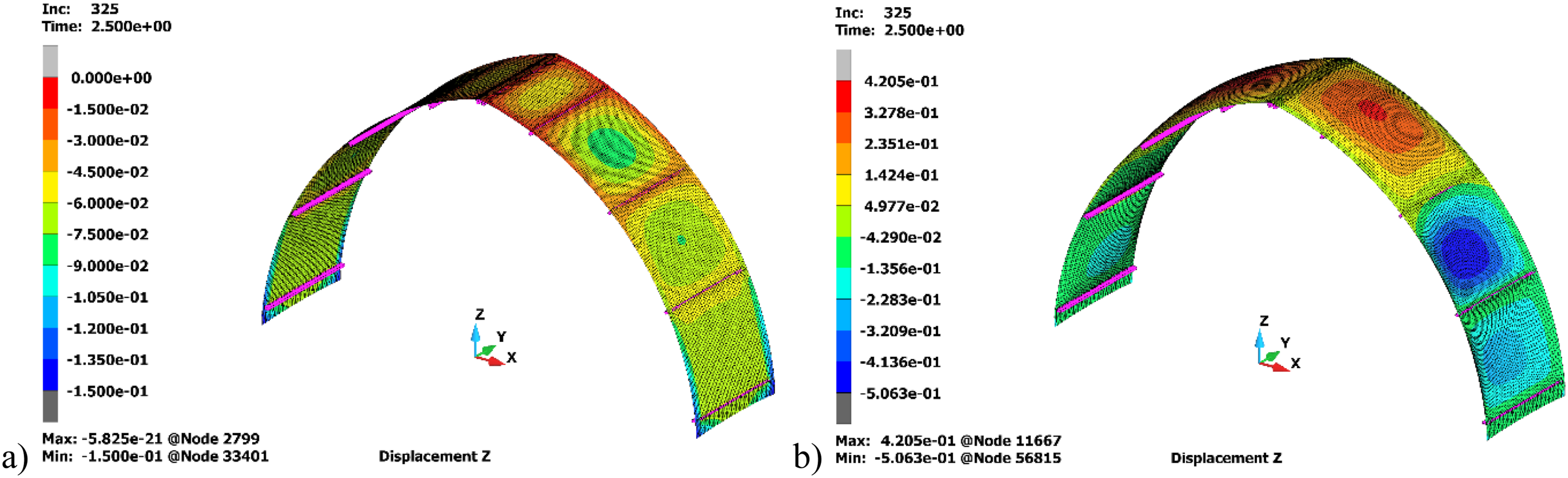
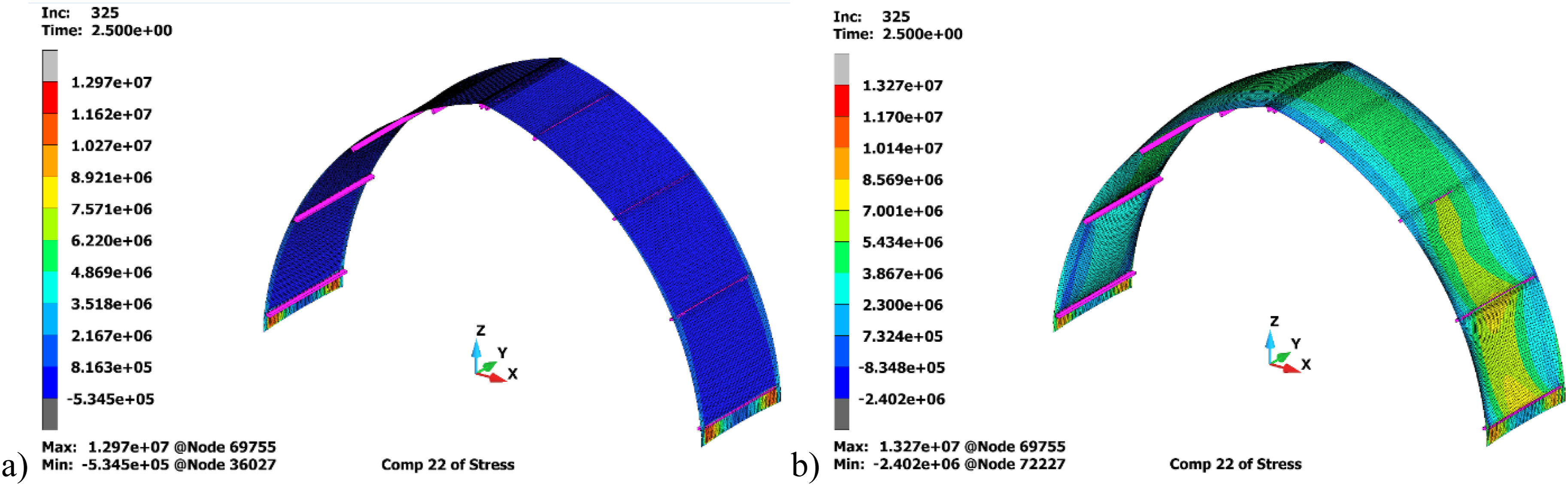
Stress analysis of the roof covering segment subjected to wind pressure (see Figures 16 and 17) indicates that the stresses in the weft direction reach 13 kN/m in the zone of maximum coated fabric pressure, while in the tear-off zone they reach a maximum of 4 kN/m. In the warp direction the stresses generally do not exceed 9 kN/m, but stress concentration produced by the extreme purlin appears again. In this region, the stresses in the roof fabric are unevenly distributed at the midspan they reach approximately 1 kN/m (Figure 17(b)), at the ends of the edge beams they reach 13 kN/m (Figure 17(a)). Locally on the leeward side of the covering the warp completely loses its stiffness by the so-called loosening (loss of tensile stresses, to probably yield fabric folding and uncontrolled mixing, see Figure 17(b)). Stresses in the fabric weft for the case of pressure loading: (a) variant 1; (b) variant 2 [1 kN/m = 106]. Stresses in the roof fabric for the case of pressure loading: (a) variant 1; (b) variant 2 [1 kN/m = 106].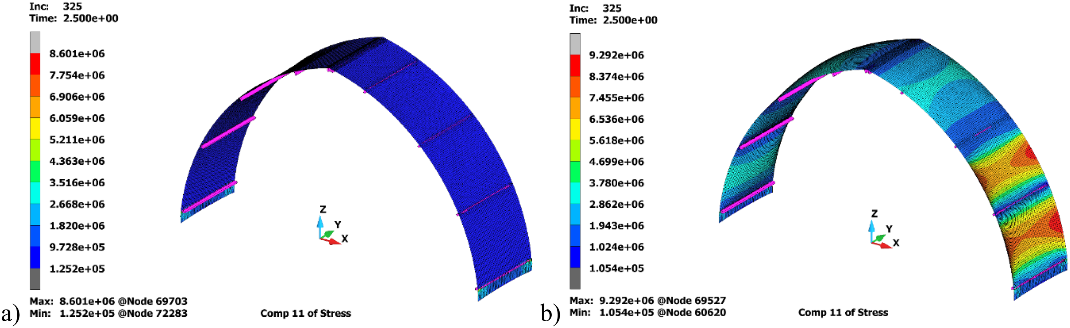
Analysis of tension beam and connecting element
The tensile beam elements were made of double RK40x40x3 mm profiles welded together by intermittent welds. The 80x40x3 mm profile was mounted in a fabric pocket approximately 35 cm long. At the ends of the tensile beam element, a connecting component (a Ø26.9 mm tube of wall thicknesses of 2.3 mm and 500 mm long) was inserted. The connecting tubes were identical for two neighbouring sections of textile roof.
Each connecting tube is to the same in two adjacent sections of fabric covering. In the middle of its length, it is attached to a transport belt, with the help of which the cover was tensioned in the vertical direction. The tension beam works in as a simply-supported beam at both ends, loaded by a tensile force of the fabric towards the warp. If we assume that the fabric is loaded to the value of the allowable tension given in (2), maximum stress at the beam midspan in the linear-elastic calculation case is 5631.3 MPa (middle point deflection 176 cm). This value significantly exceeds the allowable stress for S235 steel f
yk
= 235 MPa. The connecting elements work as a symmetrical double-cantilever beam of a span length 0.25 m. This beam is loaded with tensile beam reactions (Fz = 49.7 kN), then the maximum stress at the attachment point of the connecting element significantly exceeds allowable stresses of steel f
yk
. Inspection at the construction site proved these elements destroyed (see Figure 18). Damage of (a) tension beam; (b) connecting element.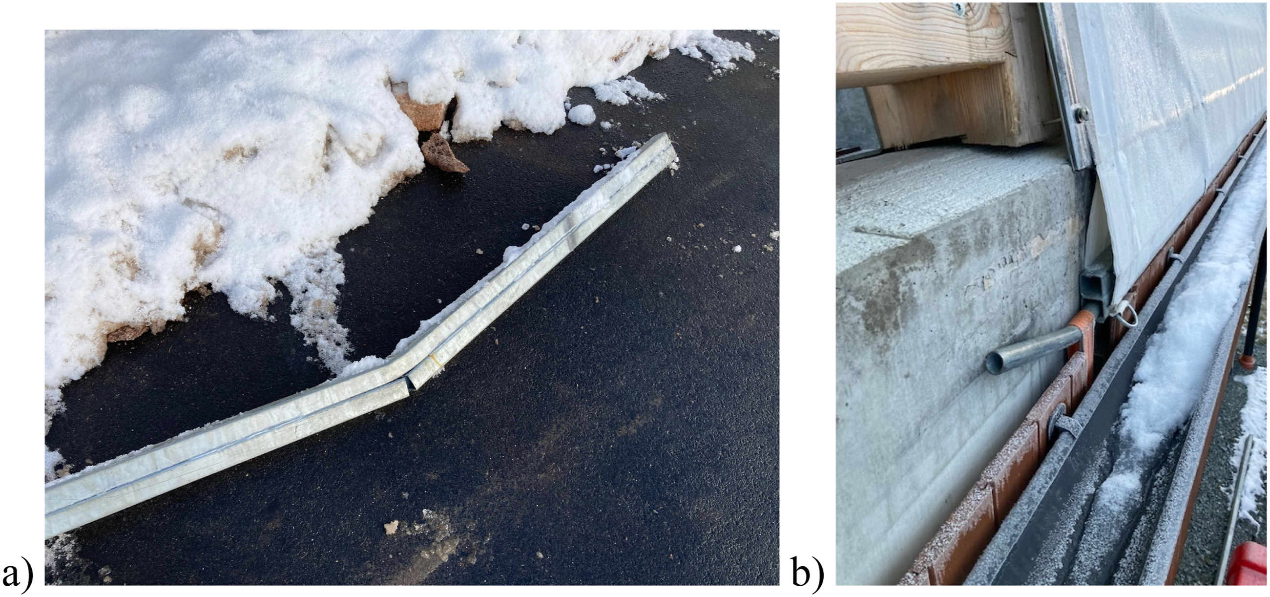
Failure roof reasons and conclusions
The coated woven fabric roof structure located in northern Poland is investigated in this paper. The designed roof shape does not properly utilise the potential and possibilities of architectural fabric. This design roof shape is dedicated to another type of roof covering. Design errors with execution contributed to the resulting roof damage.
The research domain includes material parameter assessment by testing samples in a lab and structural behaviour by finite-element modelling. The results read: • The coated fabric behaviour under biaxial stress in the range of operational stresses can be satisfactorily reflected by its behaviour under uniaxial tensile stress. • Numerical analysis indicates that the process of allowable stress exceeding in the tensioning system components (tension beams and connecting pipe elements) may occur as early as the initial tensioning stage of technical fabric. The tensioning system component damage initiates localised damage to the technical fabric of the roof covering in the lower sections of the segments, as a consequence of wind forces, it leads to complete failure of the roof covering segment. • The cross-sections of the beams and beam connectors at the tie rods (tensioning system components) do not provide sufficient load-bearing capacity (due to low cross-sectional dimension) under design loads. • The results show that the PVC-coated fabric works at stresses close to the long tensile strength (LTS), not initiating the construction failure. • The adopted method of controlling and tensioning the technical fabric only in the warp direction (the direction parallel to the roof girders) is ineffective, it leads to loosening of the technical woven fabric in the weft direction (the direction perpendicular to the roof girders) as well as in the warp direction in the midspan between the girders. • The location of structural purlins leads to contact between the coated woven fabric surface and the purlins, as a consequence of long-term use, it may lead to abrasion of fabric surface and losing its load-bearing capacity. • The lower structure purlin, together with the edge of the wall, causes stress concentration in the lower parts of the technical fabric roof segment in the course of fabric extension and wind action.
This direction of research will significantly contribute to optimizing the use of coated woven fabric materials in membrane structures to enhance its sustainability and durability. Technical assessment of every distinct roof structure made of coated woven fabric is an individual case. Complex cases require experience of civil engineering and scientific expertise. Assessment procedures and rehabilitation criteria for membrane roof structures made of coated woven fabric should be developed. Assessment techniques of architectural fabric structures require dedicated standard procedures. In the design and assessment processes of membrane structures, special attention should be paid to the method of determination and mechanical parameters performance. The paper provides scientists, engineers and designers with a technical assessment example of the roof construction made of coated woven fabric. This investigation can be regarded as an impulse towards for new investigations on tension membrane structures.
Footnotes
Authors contributions
Conceptualisation, A.A.; methodology, A.A. and P.K.; validation, A.A. and P.K.; formal analysis, A.A. and P.K.; investigation, A.A. and P.K; resources, A.A. and P.K.; data curation, A.A. and P.K.; writing—original draft preparation, A.A. and P.K.; writing—review and editing, A.A. and P.K.; visualization, A.A. and P.K.; supervision, A.A. All authors have read and agreed to the published version of the manuscript.
Funding
The authors received no financial support for the research, authorship, and/or publication of this article.
Declaration of conflicting interests
The authors declared no potential conflicts of interest with respect to the research, authorship, and/or publication of this article.
Data Availability Statement
Data will be made available on request.