






Abstract
Out-of-plane wrinkles (OPWs) severely threaten the structural reliability of carbon fiber-reinforced polymer (CFRP) composites, whereas stacking-sequence optimization can partially mitigate their detrimental effects. A VUMAT-based numerical framework incorporating 3D Hashin failure criteria and a continuous strain-softening degradation scheme was developed to assess wrinkled CFRP laminates. The model was validated against experimental results, with a maximum relative error of 2.2% in ultimate strength prediction, and successfully captured the coupled interactions between stacking sequences and OPW geometries. At the macroscopic level, multidirectional layups exhibited lower ultimate strength but enhanced damage tolerance and more gradual failure evolution compared with unidirectional layups. Parametric analysis identified an OPW aspect ratio of 0.20 as the threshold for severe stress localization. At the microscopic level, under compressive loading, interlaminar stiffness mismatch in MD layups induced extreme localization of out-of-plane normal stress, with σ33 increasing nearly 20-fold relative to the UD baseline and reaching 134.57 MPa, accompanied by elevated in-plane shear stress τ12 of 25.96 MPa. These results indicate that MD layups provide effective macroscopic damage tolerance, while the revealed three-dimensional microscopic stress amplification mechanisms should be considered in precise defect-tolerance design of composite structures.
Keywords
Introduction
Carbon fiber-reinforced polymers (CFRPs) are high-performance composite materials extensively applied in the wind energy, aerospace, and automotive sectors, owing to their exceptional specific strength, high stiffness, and excellent corrosion resistance.1,2 However, due to the inherent constraints of current manufacturing techniques, the formation of wrinkle defects remains a persistent challenge. These defects can act as dominant sources of premature failure and may eventually lead to catastrophic structural collapse. Therefore, a comprehensive investigation into the influence of wrinkle defects on the failure behavior of CFRP laminates is of paramount importance for ensuring the operational safety and structural integrity of these components.
In engineering applications, CFRP is typically utilized in the form of laminates, which are constructed by stacking individual laminae in specific sequences. Different stacking sequences result in distinct mechanical responses and damage mechanisms, 3 thereby influencing structural reliability. 4 Thus, optimizing the layup configuration 5 to achieve an effective stacking sequence is a critical strategy for fully utilizing the anisotropic characteristics of CFRP laminates.6,7 By tailoring the load-transfer paths, this approach suppresses failure initiation and delays damage propagation.8–10
To enhance the reliability11,12 and damage-tolerance potential13,14 of laminates, numerous researchers have explored the optimization of stacking sequences. In the field of composite layup design, algorithm-driven structural optimization represents an important research direction. Studies have established optimization frameworks by implementing multi-objective genetic algorithms or by coupling genetic algorithms with artificial neural networks15,16 that balance computational efficiency with engineering practicality. As the design space has expanded, the mechanical enhancement mechanisms of non-traditional layup configurations have attracted considerable attention. Studies have demonstrated that novel strategies—such as biomimetic helicoidal architectures inspired by nature, variable-stiffness curvilinear fiber paths, and “Double–Double” stacking—not only significantly enhance impact resistance but also provide distinct advantages in suppressing delamination failure.17–19
In the large-scale wind turbine blade industry, while advanced architectures represent a clear trend, traditional unidirectional (UD) and multidirectional (MD) layups remain the industrial mainstay due to cost constraints and manufacturing maturity. Additionally, through specialized angular combinations or metal-composite hybrid designs, notable improvements have been achieved in the static mechanical performance of laminates.20,21 Recently, the design paradigm for composites has progressively shifted from simple static strength assessment toward failure-controlled design and structural-functional integration. For instance, investigations into multistable lattices and flower-shaped architectures have revealed the broad application potential of composites in morphing aircraft configurations, energy dissipation, and large-deformation control.22–24 Despite substantial progress in layup design and numerical optimization,25–29 most existing models still operate under the “pristine laminate” assumption. This indicates an important gap in the current understanding of defect-sensitive laminate behavior: the lack of in-depth exploration into the nonlinear coupling mechanisms between “defect geometric features” and “layup constraint effects” within stacking sequence design. Specifically, contemporary defect mitigation strategies frequently prioritize manufacturing process refinements while overlooking how to enhance the damage tolerance of defective structures via layup optimization. This omission limits the efficacy of reliability assessments and failure-prevention strategies for composites operating in complex service environments.
In large-scale composite structures, wrinkles constitute a critical structural defect that significantly accelerates the material’s failure progression. As a result, extensive research has focused on wrinkle-induced progressive damage processes and their underlying failure mechanisms.14,30–32 Since composite materials encounter complex coupled loading conditions during actual service, direct multi-axial stress simulation presents a formidable challenge. Therefore, current research predominantly adopts a progressive strategy, prioritizing the investigation of wrinkle-induced effects under static tensile and compressive loads to establish foundational failure prediction frameworks.33–35 Studies have demonstrated that a synergistic approach—integrating experimental characterization with finite element analysis (FEA)—facilitates a profound understanding of wrinkle formation and its subsequent impact on the damage tolerance of CFRP components.36–38 While a broad consensus exists regarding the significant stiffness degradation and performance knockdown caused by wrinkles,39–41 current literature remains largely focused on quantifying the resultant “reduction” in strength. There is a distinct lack of research exploring how various stacking sequences can be utilized to redistribute internal stress and actively intervene in the failure trajectory.
Addressing the aforementioned research gaps, this study aims to reveal the structural compensation mechanisms of layup configurations regarding wrinkle defects. By developing a finite element model incorporating out-of-plane wrinkles, this study conducted a comparative analysis to evaluate stress distributions, failure evolution, and ultimate load-carrying capacities under static tensile and compressive loading. Moreover, the nonlinear coupled effects between stacking sequences and defect geometric parameters are clarified, providing a technical basis for failure prevention and damage-tolerant design in defective composite components. The remainder of this paper is structured as follows: Section 2 details the establishment of the numerical simulation framework; Section 3 analyzes and discusses the stress contours and fracture processes under static tension; Section 4 examines the mechanical response under static compression and provides a comparative discussion with the tensile results; finally, Section 5 summarizes the primary conclusions of this work.
Finite element analysis
Numerical simulations were conducted using Abaqus/Explicit (2023). To accurately characterize the nonlinear mechanical behavior of the wrinkled carbon fiber-reinforced polymer (CFRP) laminates, a user-defined material subroutine (VUMAT) was developed and implemented using Visual Studio 2019 and Intel Fortran 2020. The implicit solver (Abaqus/Standard) may encounter numerical instabilities, such as stiffness matrix singularity, convergence difficulties, and premature termination, due to the nonlinear iterative nature of the Newton–Raphson solution framework. Therefore, Abaqus/Explicit was adopted in the present study. Since the explicit algorithm does not require global stiffness matrix inversion or iterative convergence procedures, it provides superior numerical stability and computational robustness in simulating the highly nonlinear damage evolution, failure propagation, and post-buckling softening behavior of wrinkled composite laminates.
In terms of spatial discretization, the model was meshed using 3D 8-node linear brick elements with reduced integration (C3D8R). This element type was selected to mitigate shear locking, which is critical for simulating the bending-dominated behavior of the wavy plies. To suppress the artificial zero-energy modes (hourglassing) inherent in large-deformation states, the enhanced hourglass control algorithm was activated. A systematic mesh convergence study was also conducted, as illustrated in Figure 5. By comparing the responses under average element sizes of 0.6 mm, 0.5 mm, and 0.4 mm, it was demonstrated that refining the mesh from 0.5 mm to 0.4 mm yielded a peak stress difference below 0.12%. Based on these evaluations, the mesh size in the wrinkle-sensitive region was finalized at 0.5 mm to optimize the balance between computational fidelity and numerical efficiency. Additionally, an appropriate mass scaling technique was employed to improve computational efficiency while maintaining acceptable numerical accuracy. Together, these settings ensured a reasonable compromise between computational efficiency and simulation accuracy.
This section aims to systematically investigate the mechanical response and failure mechanisms of composite laminates containing wrinkle defects. First, 3D refined finite element models covering specific stacking sequences (unidirectional and multidirectional) and various wrinkle ratios were constructed through parametric modeling. Subsequently, the complex stress states of the laminates under tensile and compressive loads were simulated, and the constitutive nonlinearity and damage accumulation processes were numerically solved in conjunction with the VUMAT subroutine. Finally, by thoroughly analyzing the stress field distribution characteristics and load-displacement curves, the influence of wrinkle defects on the mechanical load-bearing capacity, failure initiation, and ultimate fracture evolution behavior of the specific layups was evaluated.
Hashin failure criteria
In this study, FEA was conducted using a VUMAT user material subroutine that incorporates the 3D Hashin failure criteria to characterize the damage and failure behavior of the composite laminates. While the traditional 2D Hashin failure criteria are widely implemented in commercial finite element software for plane-stress conditions, they are inherently insufficient for predicting the failure of wrinkled laminates. Out-of-plane wrinkles induce severe localized 3D stress states, particularly out-of-plane normal and interlaminar shear stresses, which drive premature failure. Therefore, the novelty of the material model proposed in this work lies in the development of a customized 3D progressive damage framework via a VUMAT subroutine. Unlike the conventional built-in models, this customized framework explicitly evaluates the 3D stress tensors, incorporates the local fiber misalignment angles into the constitutive calculations, and utilizes a tailored stiffness degradation scheme to capture the nonlinear softening behavior unique to the wrinkled regions in unidirectional and multidirectional layups. The Hashin criteria, developed specifically for fiber-reinforced composite materials, 42 distinguish four distinct failure modes: fiber tension, fiber compression, matrix tension, and matrix compression. The corresponding initiation conditions are defined as follows:
Fiber Tensile Failure

Fiber Compressive Failure

Matrix Tensile Failure

Matrix Compressive Failure
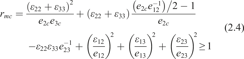
The theoretical formulations described above define four distinct failure modes, which are mathematically mapped to four specific State-Dependent Variables (SDVs) directly extracted from the explicit simulations. Specifically, the damage initiation criteria for fiber tension (Equation (2.1)), fiber compression (Equation (2.2)), matrix tension (Equation (2.3)), and matrix compression (Equation (2.4)) correspond directly to the evolution of SDV7, SDV8, SDV9, and SDV10, respectively. Once any damage initiation criterion is satisfied, the corresponding damage state variable (SDV7 to SDV10) initiates its transition from 0 (undamaged) to 1 (fully damaged). To ensure physical consistency, a progressive strain-softening evolution law was explicitly incorporated into the VUMAT subroutine. To prevent unphysical abrupt failure, these damage state variables are formulated to evolve continuously as a function of equivalent strains, accurately reflecting the gradual damage accumulation and macroscopic softening characteristics of the composite plies. To further guarantee numerical stability, the stiffness matrix components are degraded progressively as a continuous function of these state variables, rather than undergoing an instantaneous drop to zero. This continuous softening trajectory effectively prevents singular stiffness matrices and artificial zero-energy dynamic shocks, thereby improving numerical stability during the highly nonlinear explicit analysis.
Stiffness degradation model
A stiffness degradation model is a mathematical framework designed to characterize the reduction in material or structural stiffness resulting from the accumulation of damage. By incorporating damage variables—typically normalized between 0 and 1—the model quantifies the extent of degradation and defines critical damage state variables. This approach enables numerical simulations to accurately capture the progressive failure behavior of composites, spanning the entire trajectory from damage initiation and propagation to ultimate structural collapse.
The progressive stiffness degradation strategy and the corresponding mathematical formulations employed in this section are established based on the classical continuum damage mechanics framework for composites.
43
The stiffness degradation model adopted in this study is formulated as follows: Once any of the four aforementioned failure modes is identified and the corresponding internal damage variables are updated, the effective stiffness components along each principal material direction are reduced and updated according to the following expressions:







The stress update formulation is expressed as follows:

Geometric model and boundary conditions
Material properties of T300/1034-C.

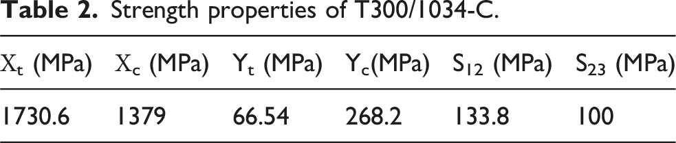
Strength properties of T300/1034-C.
The numerical investigation focuses on a rectangular laminate specimen with dimensions of 63 × 12 × 6.3 mm, discretized into 15 plies of T300/1034-C along the thickness direction. An out-of-plane wrinkle defect was incorporated at the mid-span of the laminate to represent typical imperfections encountered during the fabrication process. To evaluate the influence of layup configurations on the mechanical performance of the wrinkled structures, two distinct stacking sequences were analyzed: a UD layup, [0]15, and an MD layup, [0/±45/90/0/±45/90/±45/0/90/±45/0].
To facilitate efficient load application, reference points were established at each end surface of the model and linked via coupling constraints. Subsequently, a displacement-controlled load was applied to the primary reference point (RP-1), while the opposite reference point (RP-2) was subjected to fully constrained boundary conditions, as illustrated in Figure 1. Boundary conditions for the wrinkled composite laminate.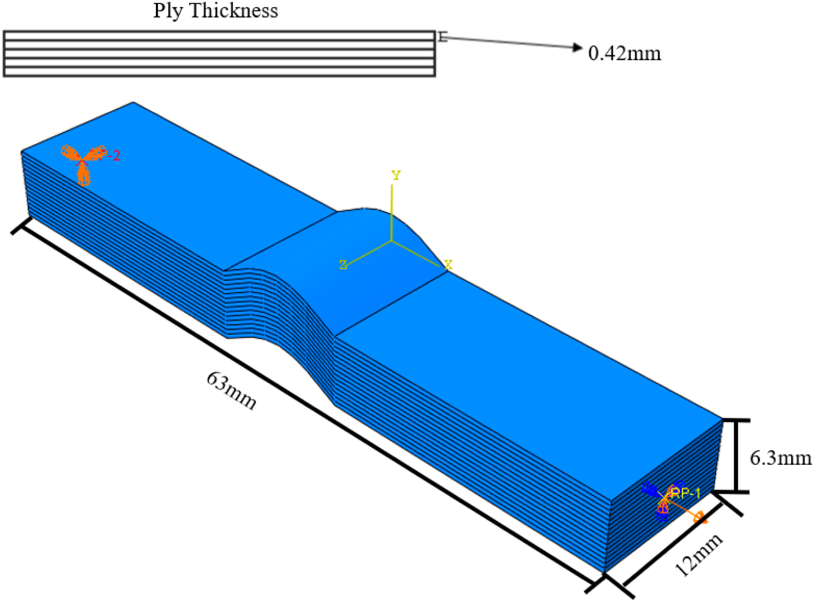
In addition, out-of-plane wrinkles with varying aspect ratios ( Geometric characteristics of the wrinkle.
To account for the large rigid body rotations and local geometric nonlinearities induced by the out-of-plane wrinkles during loading, the nonlinear geometry option (NLGEOM = ON) was activated in Abaqus/Explicit. This ensured objective strain updates within the corotational framework and maintained the accuracy of the constitutive calculations.
The wrinkle defects within the model are described using a unified mathematical formulation:
The macroscopic geometry and boundary conditions of the composite specimen were established in strict accordance with standard testing configurations, as shown in Figure 3. The specimen was modeled as a 12-mm-wide straight strip, featuring an out-of-plane wrinkle (OPW) centrally located within the gauge section. Global mesh and localized mesh refinement.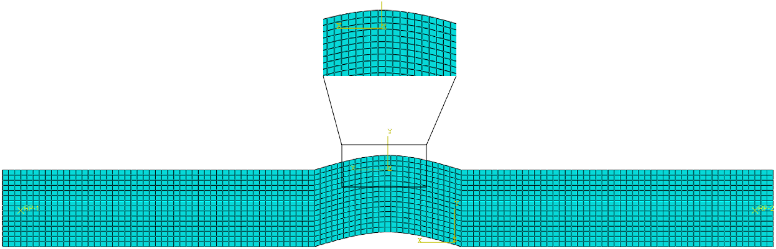
The precise geometric parameterization of the OPW is fundamentally defined by its characteristic length L, amplitude A, and the localized fiber misalignment angle θ(x), as detailed in the theoretical schematic in Figure 2. These parameters collectively determine the morphological severity of the defect.
To explicitly illustrate how this theoretical modeling is translated into the high-fidelity numerical framework, Figure 3 presents the corresponding finite element mesh configuration. As depicted in the cross-sectional view, a refined solid element mesh (C3D8R) was explicitly deployed through the thickness at the wrinkled region. This localized mesh refinement strategy ensured sufficient computational precision to capture the severe 3D stress gradients and the subsequent progressive damage evolution induced by the fiber misalignment.
It is worth noting that in the practical vacuum infusion process utilized for wind turbine blades, laminates typically exhibit a single flat surface due to the constraint of rigid molds, while wrinkles manifest internally or on the opposite side (Figure 4b). The full-thickness cosine-shaped wrinkle model adopted in this work (Figure 4a) served as an equivalent geometric representation of out-of-plane wrinkles. This idealized model was designed to decouple the complex interference of asymmetric boundary conditions, allowing for a focused exploration of the mechanical and failure coupling mechanisms between fiber curvature and stacking sequence by utilizing the aspect ratio Schematic of the modeling approaches: (a) parametric characterization of out-of-plane wrinkles; (b) process-based manufacturing model.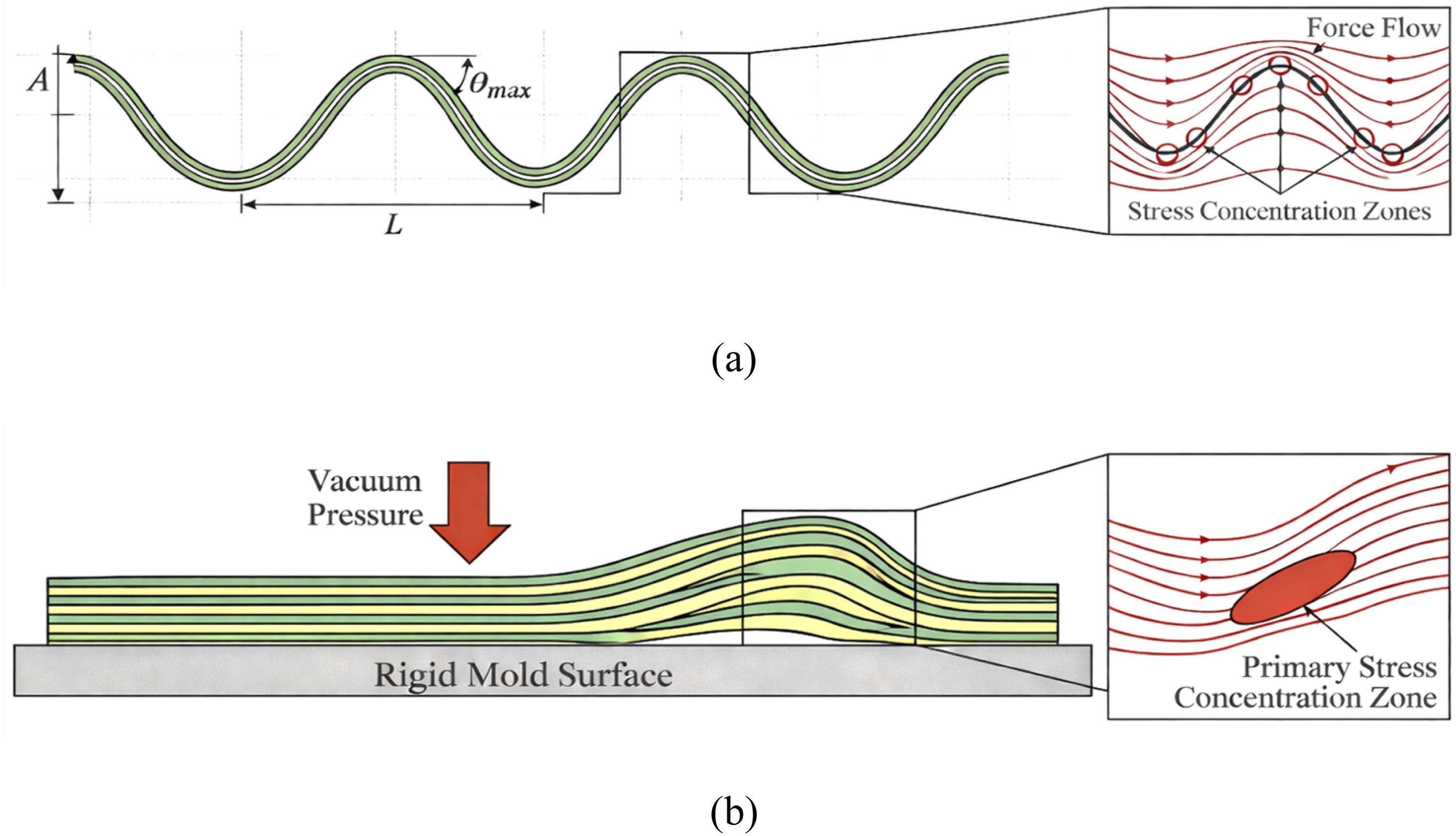
To rigorously investigate the fundamental failure mechanisms induced by the out-of-plane wrinkle (OPW), a bounding strategy was employed for the selection of stacking sequences. Specifically, two representative layups were selected as limiting cases: a unidirectional layup and a multidirectional layup. The unidirectional layup serves as the fundamental mechanical baseline to isolate the purely geometric influence of fiber waviness, eliminating any interlaminar mismatch. Conversely, the multidirectional layup represents the complex stress state of realistic engineering composites (e.g., wind turbine blades), where interlaminar stiffness mismatch is prominent. This specific selection criterion enables a targeted parametric comparison to isolate the coupling effects between geometric defects and sequence-induced stiffness variations.
Mesh generation
Regarding spatial discretization, the model was meshed using 8-node linear brick elements with reduced integration (C3D8R), with an average element size of 0.5 mm. A mesh convergence study was conducted using the MD layup (10% wrinkle aspect ratio) under compressive loading as a representative case. Three element sizes—0.6 mm, 0.5 mm, and 0.4 mm—were compared. Figure 5 illustrates the stress-displacement curves for these different mesh densities. It is observed that refining the mesh from 0.5 mm to 0.4 mm results in negligible changes to the ultimate stress and overall curve morphology, with a peak stress deviation of less than 0.12%. Conversely, a coarser mesh of 0.6 mm leads to a slight overestimation of the peak stress and a more gradual softening stage. These results indicate that numerical convergence is satisfactorily achieved when the element size is 0.5 mm or smaller. Hence, considering both computational accuracy and efficiency, an element size of 0.5 mm was adopted for all subsequent analyses. Stress-displacement curves under various mesh refinements.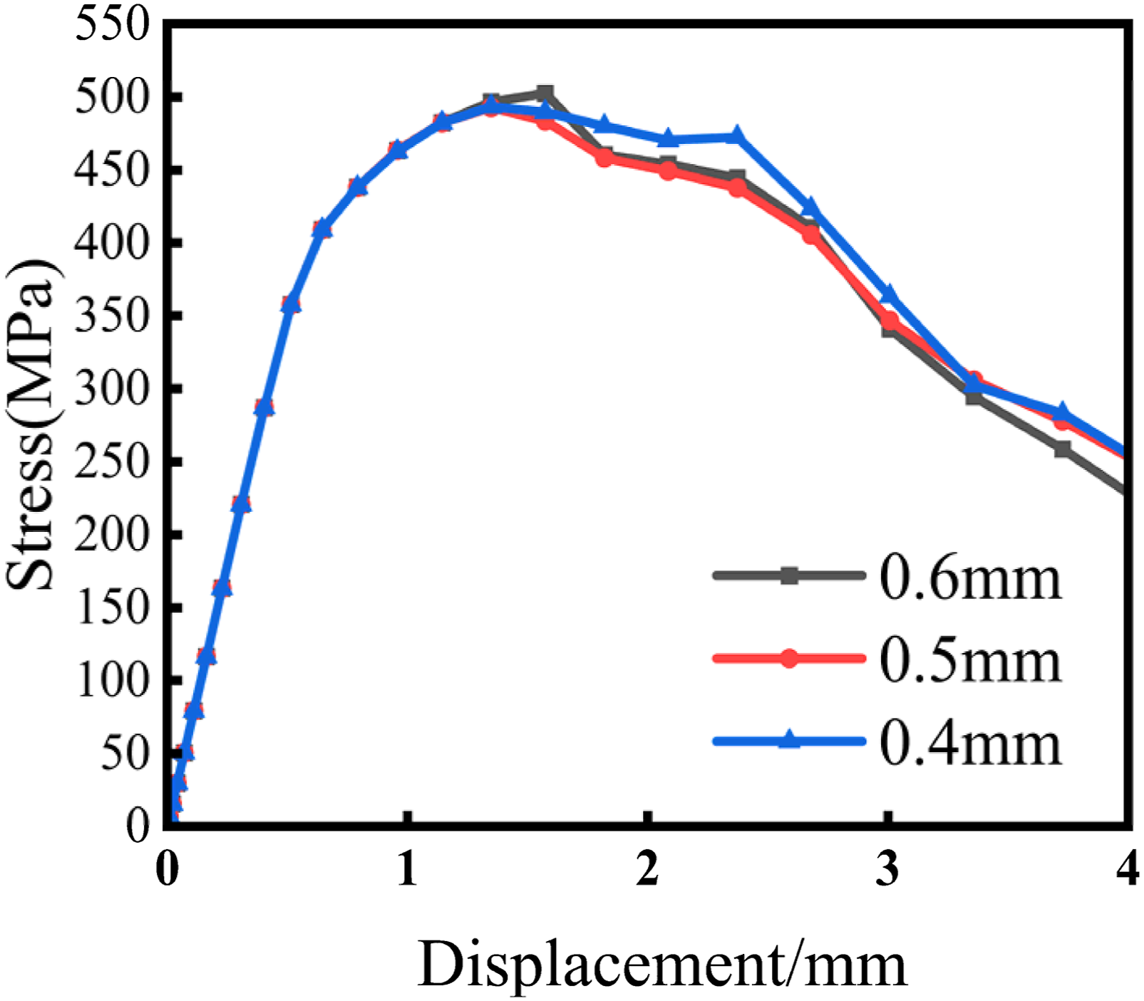
Model validation
To evaluate the fidelity and validity of the developed VUMAT subroutine, a comprehensive validation strategy utilizing both external and internal benchmarks was adopted.
Material properties of T300/YH69.

Strength properties of T300/YH69.
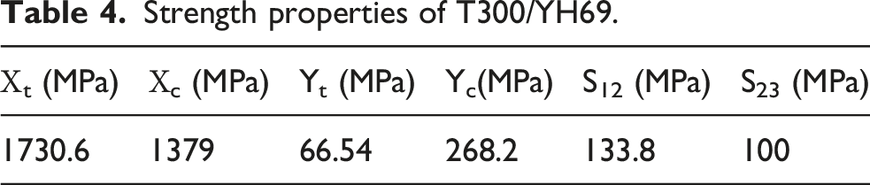
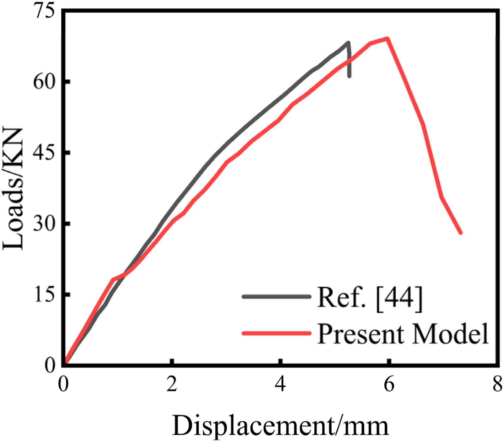
Validation of the proposed numerical model against experimental data from Guo et al.
Second, to specifically evaluate the performance degradation and failure mechanisms induced by wrinkles, a rigorous set of internal parametric benchmarks was established. Specifically, the unidirectional laminate was utilized as the fundamental mechanical baseline to isolate the localized stress surge effects (e.g., interlaminar stiffness mismatch) induced by complex multidirectional layups. Concurrently, the 10% wrinkle ratio was selected as the reference case for evaluating the effect of increasing wrinkle severity.
In summary, this analytical framework, grounded in an external experimental benchmark and internal parametric baselines, provides a foundation for extending the analysis to complex 3D mechanical responses involving out-of-plane wrinkles.
Static tensile response and failure analysis of wrinkled CFRP laminates
This section provides a comprehensive analysis of the mechanical response of wrinkled laminates under static tension. By examining different layup configurations and wrinkle geometries, this section elucidates the correlation between stress fields, progressive damage evolution, and ultimate load-bearing capacity.
Tensile performance and progressive damage evolution of multidirectional fiber-reinforced layups
Tensile performance and progressive damage evolution of MD layups
Figure 7 illustrates the evolution of internal stress fields within the laminate under tensile loading. The stress contours show that high-stress regions are primarily concentrated in layers 1, 5, 11, and 15 (all 0° plies), which is consistent with the symmetric stacking sequence centered at the 8th layer. Due to their superior axial stiffness, the 0° plies function as the primary load-bearing constituents. Within the wrinkled region, the 0° fibers undergo local deflection, causing a pronounced increase in axial stress and the formation of pronounced stress concentrations. In contrast, the 90° plies contribute minimally to the axial load path due to their low effective stiffness in the loading direction, resulting in relatively low stresses. The ±45° plies primarily participate through shear deformation, facilitating a degree of stress redistribution for the 0° plies, which prevents significant stress localization in these layers. Axial stress contours for MD wrinkled layups under tensile loading: (a) 5%, (b) 10%, (c) 12%, (d) 15%, and (e) 20% wrinkle aspect ratios.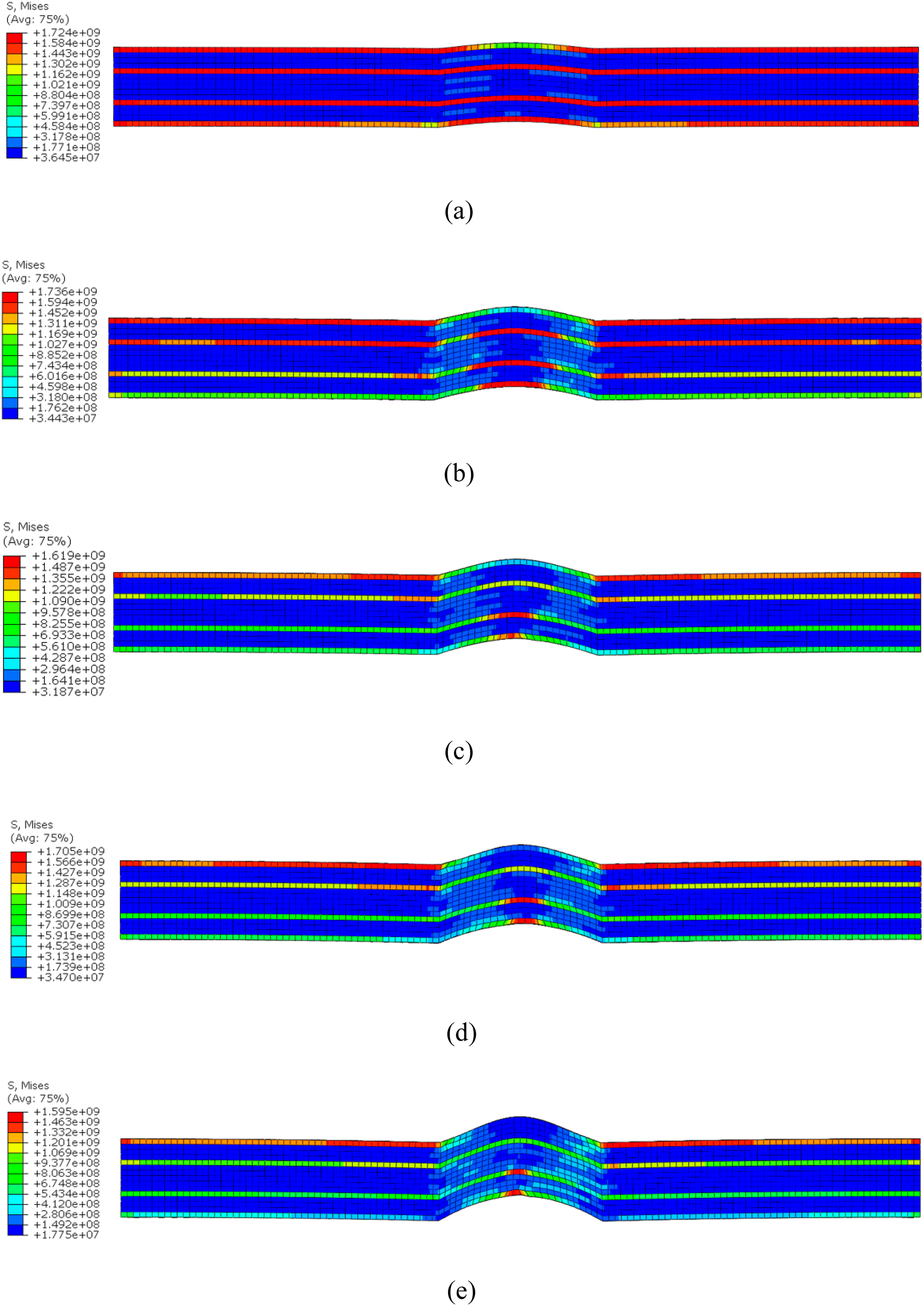
As the wrinkle aspect ratio (
Analysis of the progressive failure and fracture process
The failure evolution characteristics of the laminates demonstrate a marked dependence on wrinkle geometry. Both damage initiation locations and fracture trajectories are controlled by the wrinkle aspect ratio, resulting in distinct failure morphologies across the five configurations.
For the laminates with 5% and 10% aspect ratios (Figure 8), the specimens undergo uniform tensile deformation during the early loading phase. Damage onset is first identified at the interface between the wrinkled zone and the adjacent pristine region above the wrinkle. As the tensile load increases, the crack trajectory migrates toward the intrados (lower concave region) of the wrinkle. The subsequent expansion and coalescence of localized cracks eventually culminate in the structural failure of the laminate. Axial stress contours illustrating the progressive fracture evolution of MD wrinkled layups under tensile loading: (a) 5% aspect ratio; (b) 10% aspect ratio.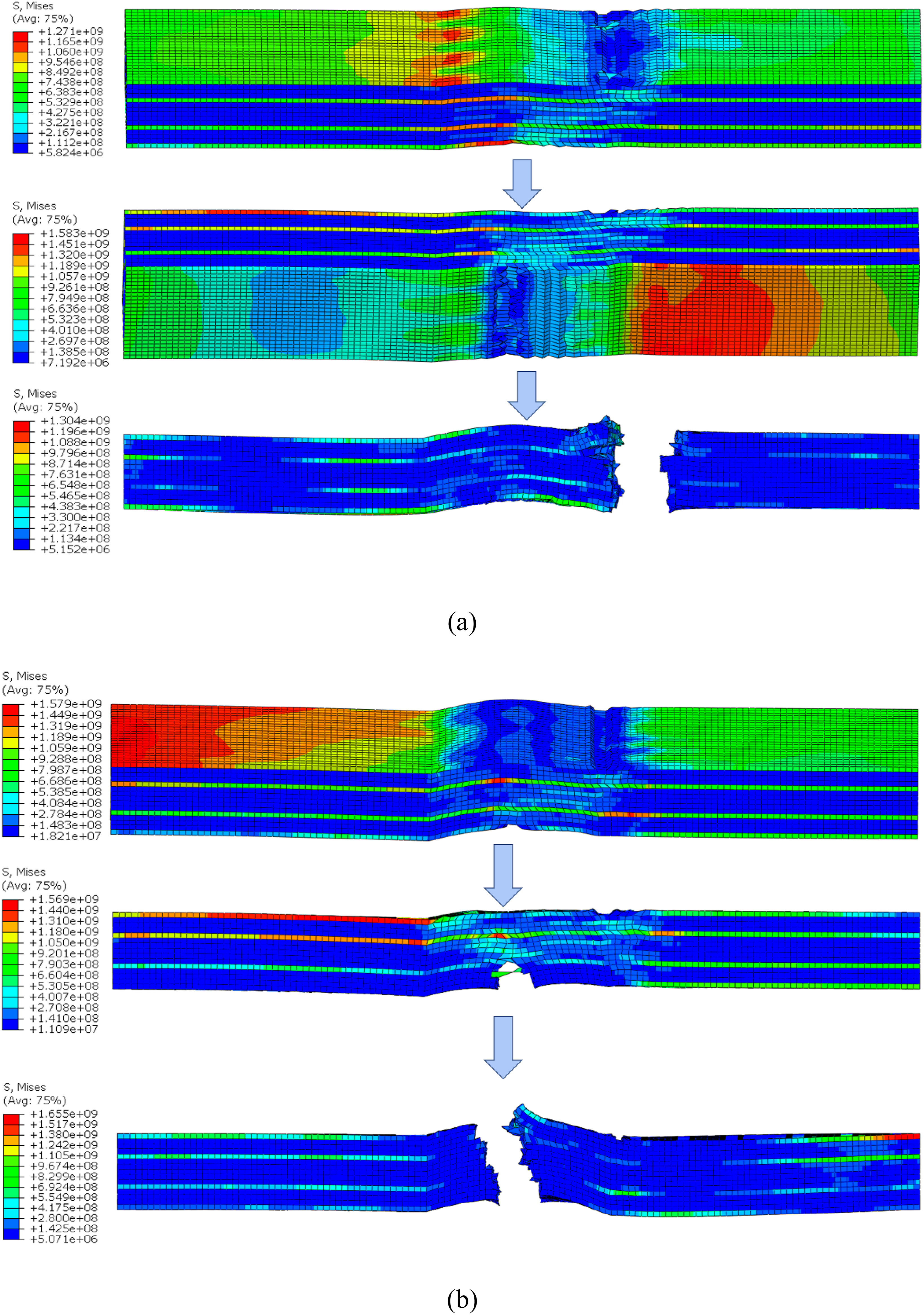
For the laminate with a 12% aspect ratio (Figure 9), crack initiation occurs directly within the concave region of the wrinkle under sustained tensile loading. The crack subsequently undergoes rapid propagation across the entire cross-section, resulting in the ultimate fracture and failure of the laminate. Progressive failure and stress distribution of a 12% aspect ratio wrinkled MD layup under tension.
In high-severity cases ( Axial stress contours illustrating the progressive tensile fracture evolution of MD wrinkled layups: (a) 15% aspect ratio; (b) 20% aspect ratio.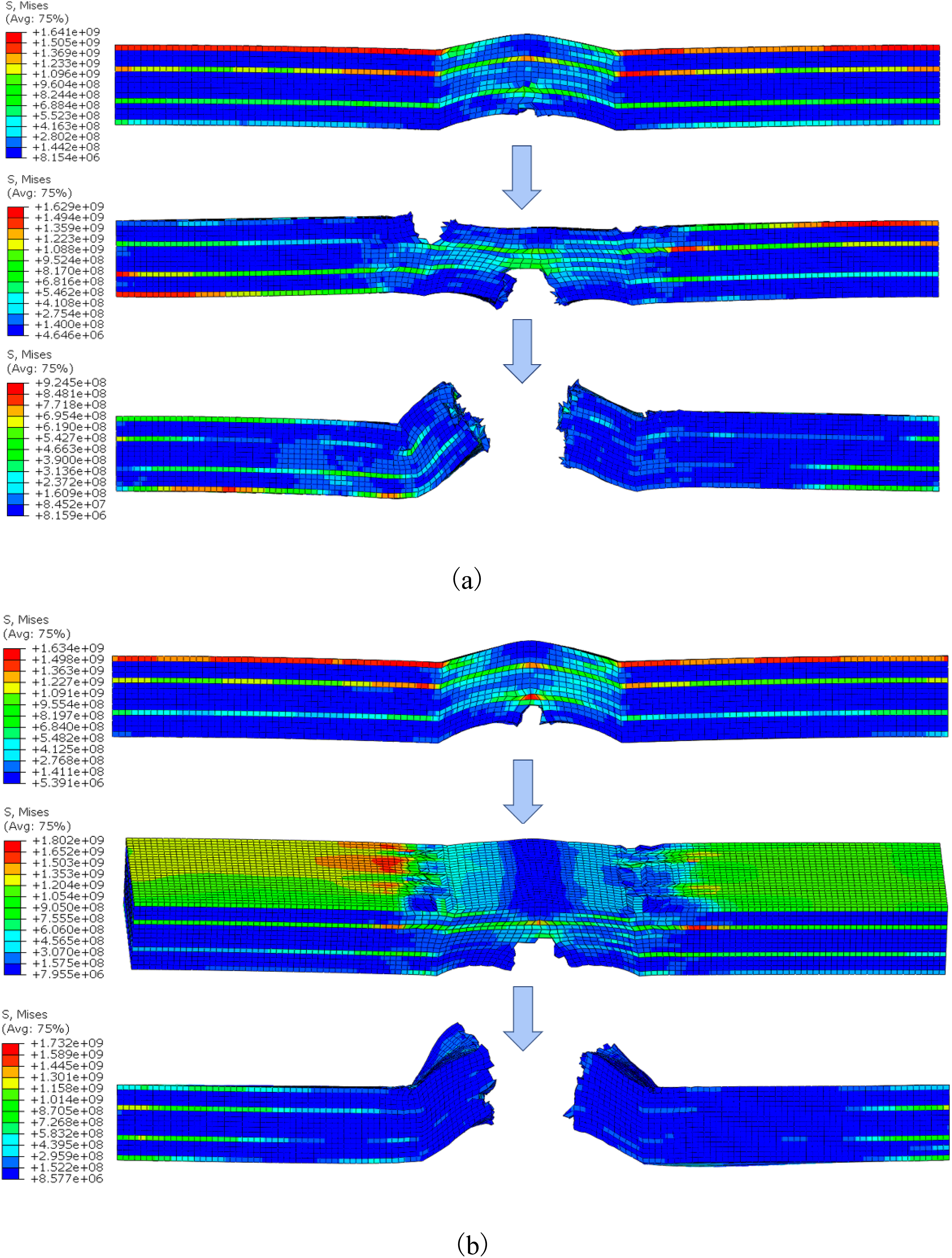
The observed variations in fracture behavior are fundamentally governed by the stress field distribution, which is intrinsically driven by the geometric attributes of the wrinkles. At lower aspect ratios (5% and 10%), the wrinkles are relatively shallow; nevertheless, significant curvature gradients exist at the transition zones between the wrinkle and the pristine laminate. Under tensile loading, the fibers in these regions tend to align with the loading axis—a phenomenon known as the “fiber straightening effect”—which induces severe localization of interlaminar shear and transverse normal stresses. As a result, failure is first initiated within these transition zones. Following local stiffness degradation, the load progressively redistributes toward the lower concave region, namely the intrados where fiber misalignment and curvature are most pronounced. The synergistic interaction of tensile and shear stresses in this region ultimately triggers localized fracture. Under continued loading, the sustained reduction in both the effective load-bearing cross-sectional area and local stiffness culminates in the complete structural failure of the laminate at its weakest link.
In the 12% case, the intensified fiber deflection in the concave region elevates the local stress state until it predominates over the boundary stress concentrations. This shift in the governing stress field results in localized fracture at the intrados, followed by rapid, unstable crack propagation that leads to the ultimate failure of the specimen.
For severe wrinkles (
Analysis of tensile failure characteristics and stress localization in unidirectionally reinforced laminates
Analysis of stress contours
As illustrated in Figure 11, the global stress distribution within the unidirectional ([0]15) wrinkled laminate under tensile loading parallels the trends observed in the multidirectional cases discussed previously, specifically manifesting as a high propensity for stress localization within the wrinkled region. In contrast, the spatial extent of the stress concentration in the UD [0]15 layup is considerably broader. The finite element results elucidate that such laminates exhibit pronounced unidirectional load-carrying behavior and a high degree of anisotropy, which strongly influences the resulting stress field. Axial stress contours for UD wrinkled layup under tensile loading: (a) 5%, (b) 10%, (c) 12%, (d) 15%, and (e) 20% wrinkle aspect ratios.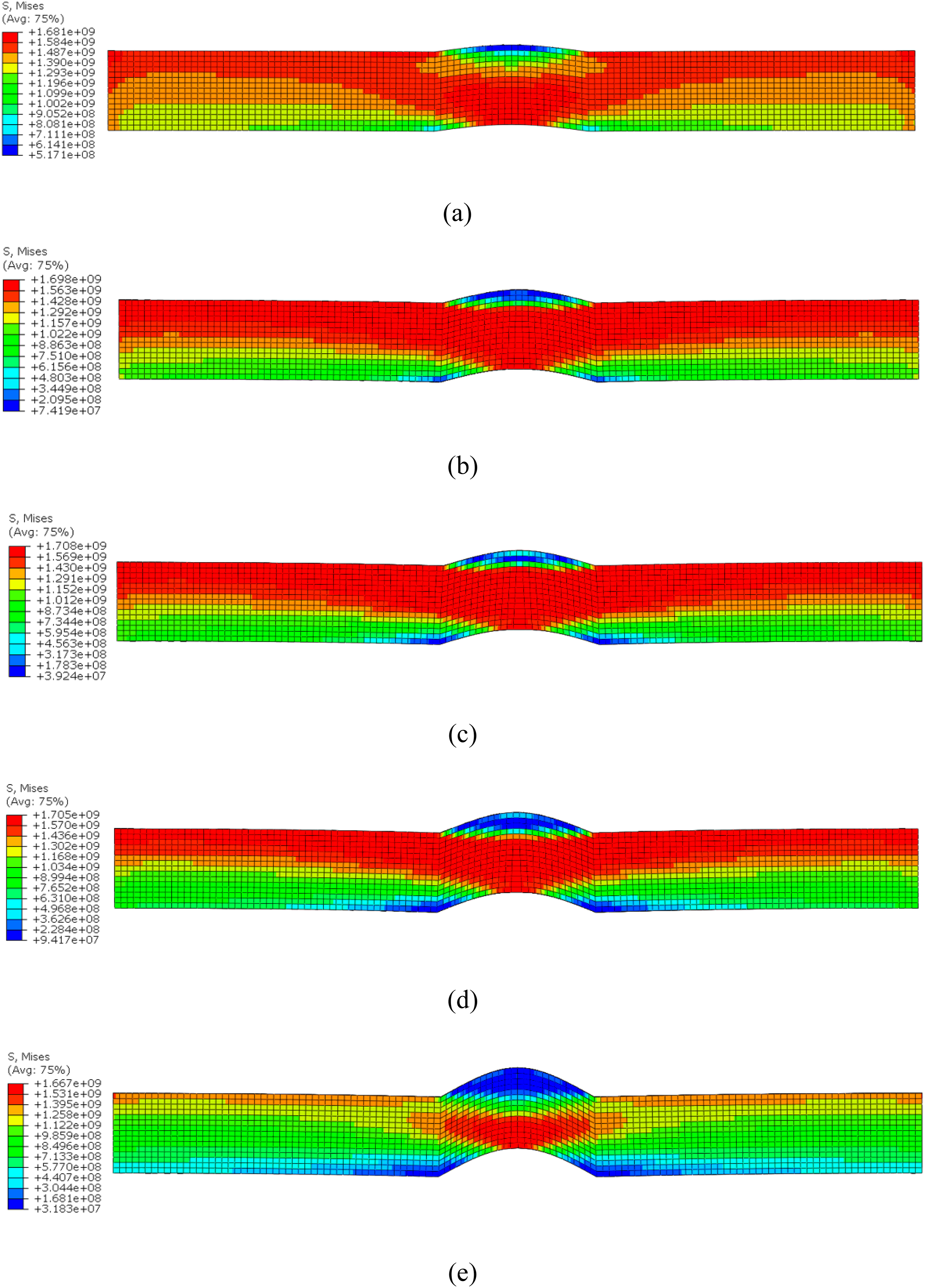
Under tensile loading, the 0° fibers collectively sustain the axial tension. Due to the absence of 90° and ±45° plies—which would otherwise provide structural constraint and facilitate in-plane load sharing—a significant localized bending moment is generated near the wrinkle. This induces out-of-plane normal and interlaminar shear stresses through the thickness of the laminate. The stress concentration is thus no longer confined to the point of maximum curvature; instead, it manifests as a band-like distribution extending along the wrinkle slopes and into the adjacent transition zones. Since the fiber orientations are identical across all layers, the load cannot be effectively redistributed through the interlaminar shear synergy typical of multidirectional configurations. Instead, interlaminar load transfer is primarily governed by the matrix and fiber-matrix interface shear properties. This results in a more pronounced collective load-bearing response within the wrinkled region, which ultimately expands the spatial extent of the stress concentration.
Simultaneously, it is observed that for aspect ratios of 5%, 10%, 12%, and 15%, the stress-intensified zones are distributed over relatively expansive areas encompassing the wrinkle and its adjacent regions. Conversely, when the aspect ratio reaches 20%, the high-stress region undergoes a distinct transition toward localization at the wrinkle intrados, with stress concentration becoming sharply focused at the trough and its immediate boundaries. In the low-to-moderate aspect ratio range, while the curvature increases with the aspect ratio, the wrinkle wavelength and global stiffness are sufficient to allow the combined effects of local bending and in-plane tension to act over a broader domain; thus, the stress field remains relatively diffuse despite the increasing intensity. Conversely, at the 20% threshold, the acute fiber deflection and misalignment at the intrados result in a substantial localized reduction in structural stiffness. This triggers a severe load redistribution, forcing interlaminar shear and out-of-plane normal stresses to concentrate intensely within the wrinkle trough. Accordingly, the stress contours exhibit a highly localized characteristic, signifying a shift in the governing failure mechanism.
Analysis of progressive failure and fracture evolution
The fracture trajectories of UD [0]15 layups demonstrate a marked sensitivity to the wrinkle aspect ratio ( Stress distribution at different fracture increments for UD [0]15 layups: (a) 5% aspect ratio; (b) 20% aspect ratio. Sequential stress contours illustrating the tensile fracture evolution in UD wrinkled layups at various damage stages: (a) 10%, (b) 12%, and (c) 15% aspect ratios.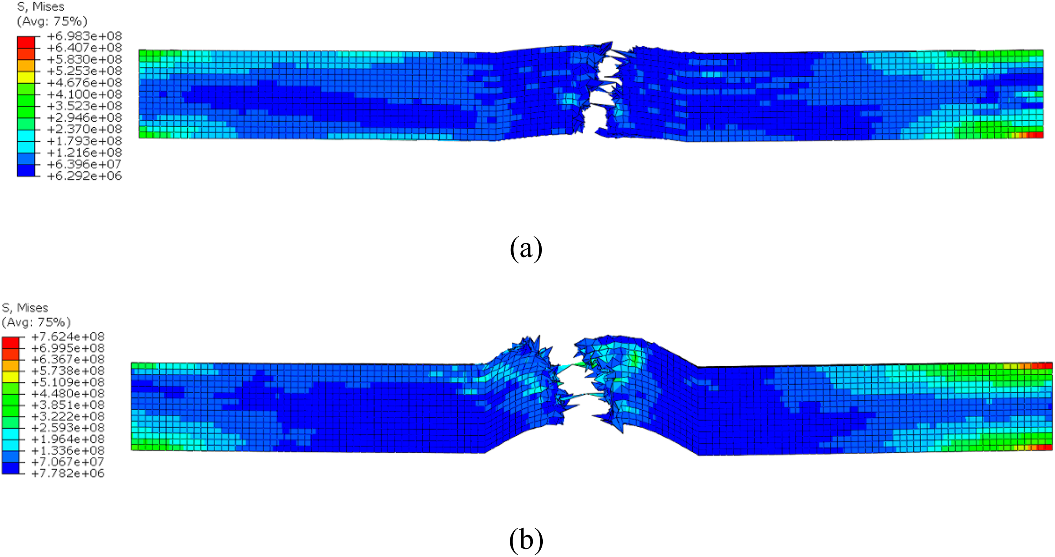
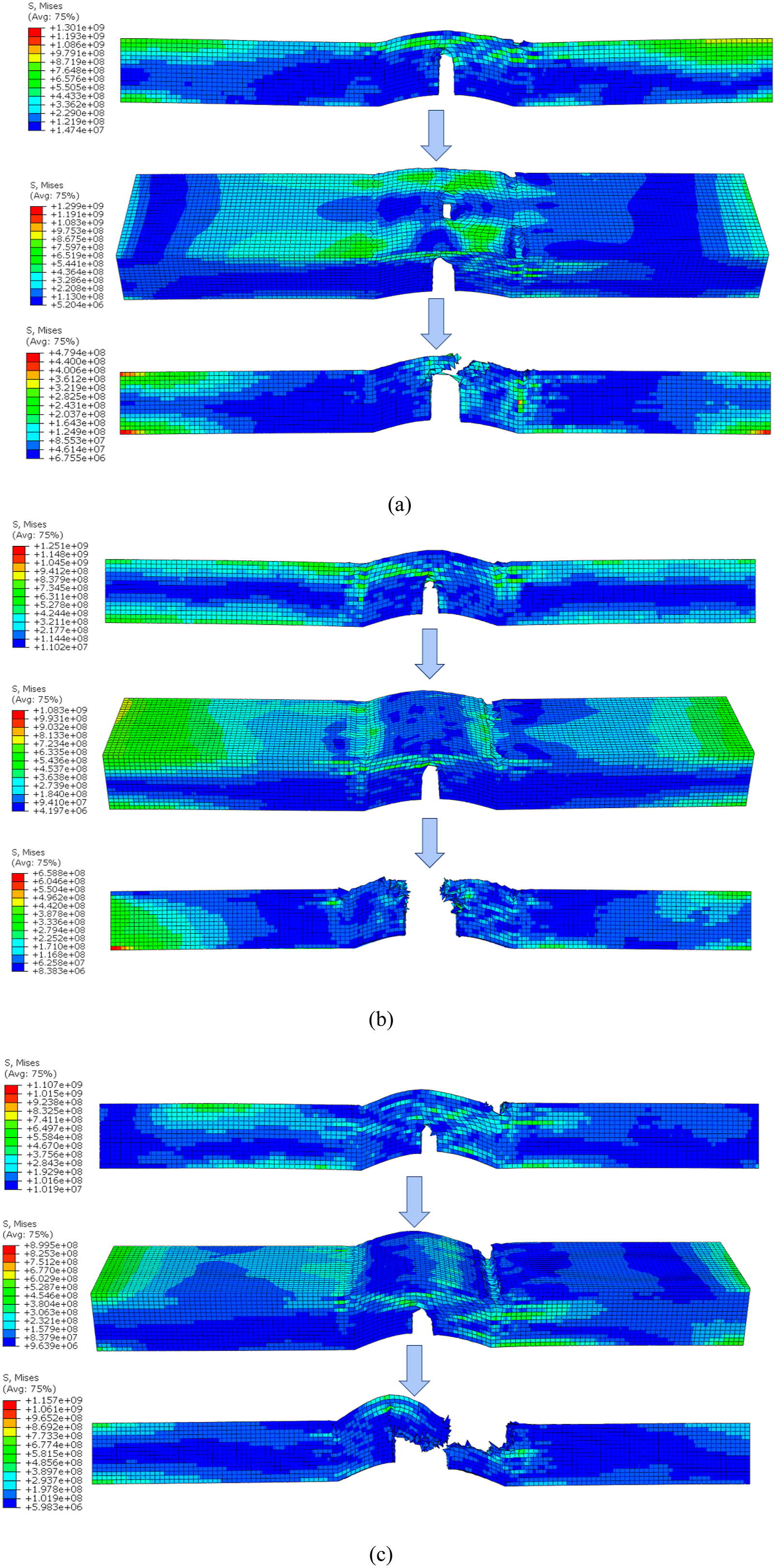
The aforementioned variations are fundamentally dictated by the geometric characteristics of the wrinkle and the resulting load-path alterations. In the 5% aspect ratio case, the low curvature implies a negligible geometric perturbation. While matrix initiation occurs at the intrados, the gradient in mechanical properties relative to the virgin laminate is too low to drive a shift in the stress field. As a result, the fracture remains localized at its origin, leading to a sudden fracture across the wrinkled cross-section. Unlike higher aspect ratio cases, this configuration lacks the necessary stress-redistribution capacity to facilitate failure migration into the transition zones.
The fracture progression for 10%–15% aspect ratio laminates exhibits a mechanistic similarity to the high-severity MD layup discussed earlier. The intensification of wrinkle geometry elevates local interlaminar stress components at the trough, leading to damage onset. The resulting loss of local constitutive integrity necessitates a load-path shift toward the wrinkle boundaries (transition zones), where stress concentrations trigger further rupture. The reduction in the structural load-carrying area, coupled with the synergistic interaction of localized damage zones, culminates in ultimate failure at the specimen’s critical cross-section.
While the 20% aspect ratio configuration exhibits a failure pattern similar to the 15% case at a macroscopic level, its governing physics differs. The intensified geometric severity results in a highly localized stress state at the wrinkle trough that surpasses material strength before a load-sharing response can be activated. Unlike the progressive failure observed at lower aspect ratios, the 20% case is characterized by a rapid, unstable transverse rupture originating at the intrados. The stress fields confirm this behavior, showing a concentrated failure zone that lacks the spatial migration typical of load-redistributing structures.
Our numerical results indicate that MD layups undergo a complex sequence of coupled damage evolution. Matrix failure onset originates in the off-axis ±45°layers near the wrinkle trough, governed by the Hashin tensile criterion. The resulting loss of local constitutive integrity necessitates a stress migration toward the longitudinal 0° reinforcements. Final structural collapse is dictated by the 0° fiber failure reaching its critical threshold. While the MD layup facilitates superior damage tolerance through ply interaction, the UD layup exhibits a high degree of defect sensitivity; without shear-lag support from transverse plies, it suffers from abrupt brittle failure immediately upon fiber rupture at the defect site.
Analysis of stress-displacement response and ultimate load-carrying capacity under static tensile loading
As shown in Figure 14 and Table 5: Tensile stress-displacement curves for wrinkled laminates: (a) MD layups with 5% and 10% aspect ratios; (b) MD layup with a 12% aspect ratio; (c) MD layups with 15% and 20% aspect ratios; and (d) UD layups with aspect ratios ranging from 5% to 20%. Peak stress values for different configurations under tensile loading.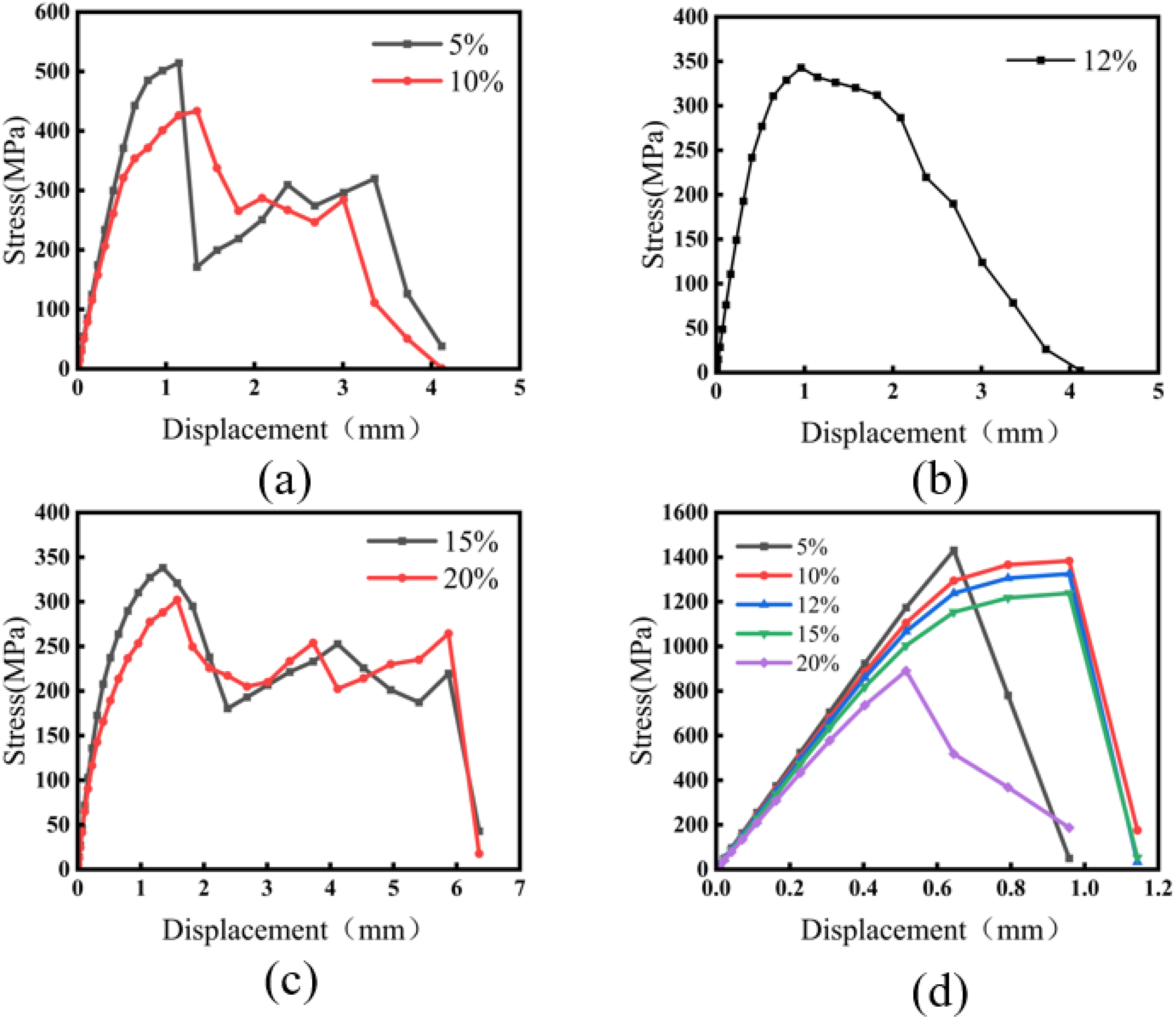
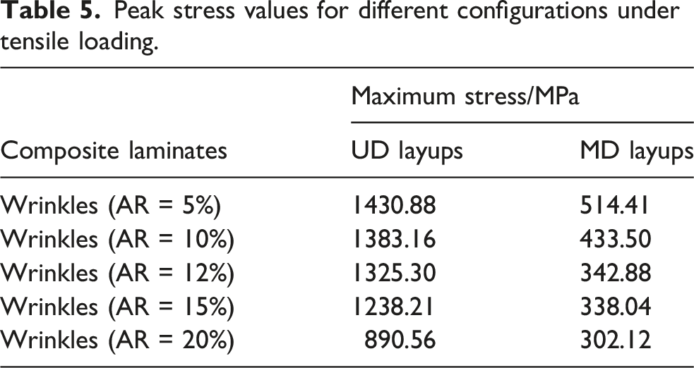
At equivalent wrinkle severities, UD layups maintain superior ultimate stress levels due to higher fiber efficiency in the loading direction. The peak capacity of a laminate is a function of its axial fiber content and constitutive stiffness. Since all UD fibers are oriented at 0°, they provide maximum resistance to axial tension, outweighing the detrimental effects of the wrinkle when compared to the performance of MD layups. The inclusion of ±45° and 90° plies in MD layups—while beneficial for multi-axial loads—offers minimal reinforcement in the primary tensile direction. This reduction in effective longitudinal stiffness lowers the overall load-bearing ceiling, leading to earlier failure at lower stress magnitudes.
While UD layups exhibit superior peak load capacity, MD layups demonstrate greater ductility, requiring more extensive displacement prior to total failure. The stress-displacement response highlights the high-strength, low-toughness nature of the UD configuration. Wrinkles trigger localized strain concentrations which, lacking the redistributive effects of off-axis plies, lead to acute stress fields. Exceeding the fiber strain threshold results in abrupt rupture and a catastrophic loss of structural integrity. This is marked by a rapid post-peak load shedding in the stress-displacement curve, indicating a very narrow margin between initial failure and complete collapse.
MD layups are characterized by enhanced damage tolerance and a non-catastrophic failure progression. While the longitudinal 0° plies sustain the bulk of the axial tensile load, the off-axis ±45° and 90° plies offer critical shear reinforcement and lateral confinement. The resulting interlaminar stress gradients at the ply interfaces—driven by the orientation mismatch—facilitate the onset of matrix cracking and delamination. These dissipative mechanisms effectively absorb energy, ensuring that the laminate maintains constitutive integrity post-initiation. This progressive damage evolution prevents instantaneous collapse and sustains the load-bearing capacity throughout the failure process.
Numerical results of wrinkled composite laminates under static compression and comparative analysis of tensile and compressive responses
While Section 3 provided a systematic numerical analysis of the stress distribution, fracture evolution, and load-bearing performance of wrinkled composite laminates under static tensile loading, the present section further investigates these foundations. Here, we further investigate the mechanical response characteristics of the same models under compressive loading. A comparative analysis between the compressive and tensile results is conducted to elucidate the mechanisms by which wrinkle severity and stacking sequences drive performance disparities under these distinct loading regimes.
Analysis of stress contours under static compressive loading
Comparing Figures 7–10 with Figure 15 reveals that the global stress distribution patterns in MD layups remain relatively consistent across both loading regimes, without obvious differences in stress concentration patterns. In contrast, UD layups demonstrate a marked loading-direction dependency; the stress concentration zones are notably more localized under compression than under tension. Additionally, as the wrinkle aspect ratio increases, the stress field undergoes progressive localization toward the concave intrados of the wrinkle. Axial stress contours for MD (top) and UD (bottom) wrinkled layups under static compression for varying aspect ratios: (a) 5%, (b) 10%, (c) 12%, (d) 15%, and (e) 20%.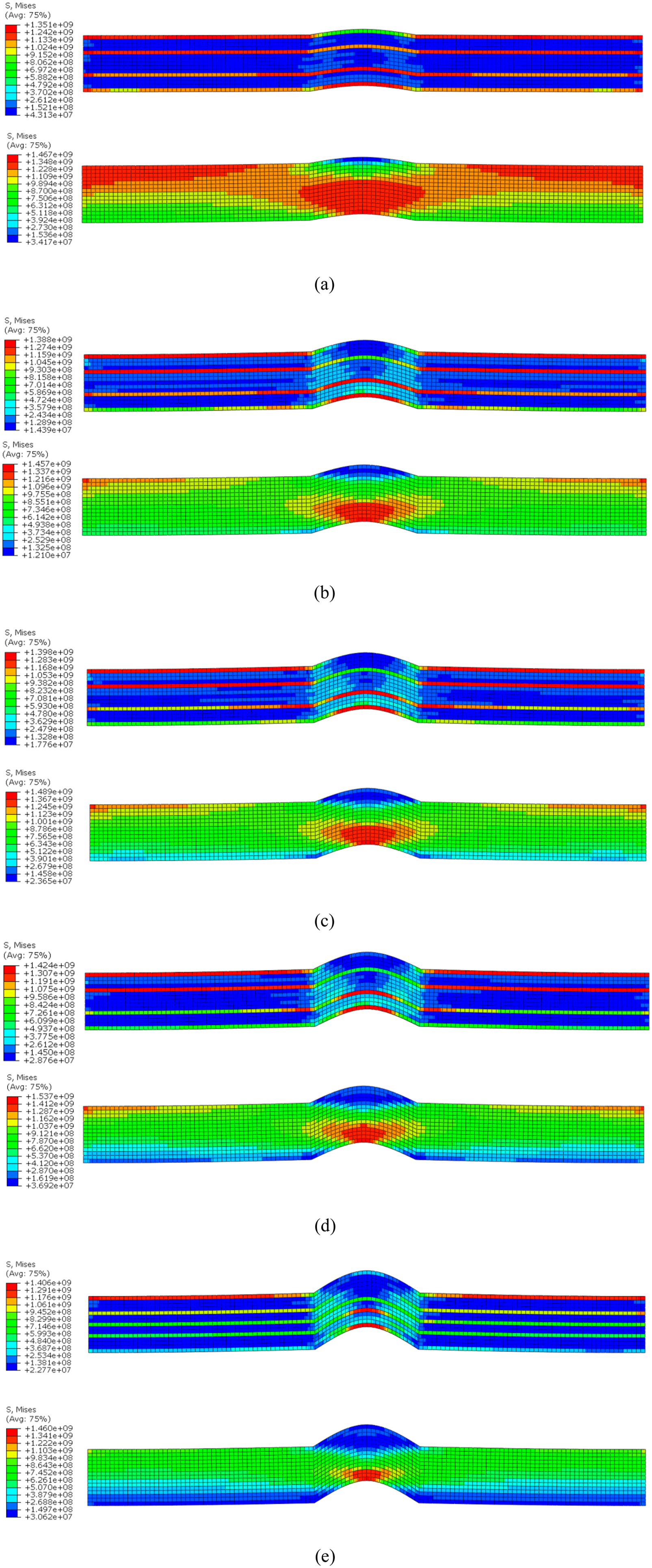
In UD layups, where all plies are aligned with the loading axis, the 0° fibers undergo pronounced local bending within the wrinkled region under compressive loading. The high curvature at the wrinkle intrados exacerbates the susceptibility to local micro-buckling, resulting in a highly localized and intense stress concentration zone. Conversely, under tensile loading, the global response is primarily governed by the axial stiffness of the fibers, resulting in stress-elevated zones that exhibit a significantly more extended and diffuse distribution.
Characterization of compressive failure mechanisms
As illustrated in Figure 16, the failure morphology of MD layups under compressive loading is primarily characterized by global buckling instability, which ultimately results in structural failure. Conversely, UD layups undergo localized micro-buckling or shear-compression failure (shear crippling) specifically at the wrinkle site. Stress contours and failure morphology of wrinkled laminates under compressive loading: MD (top) and UD (bottom) configurations with aspect ratios of (a) 5%, (b) 10%, (c) 12%, (d) 15%, and (e) 20%.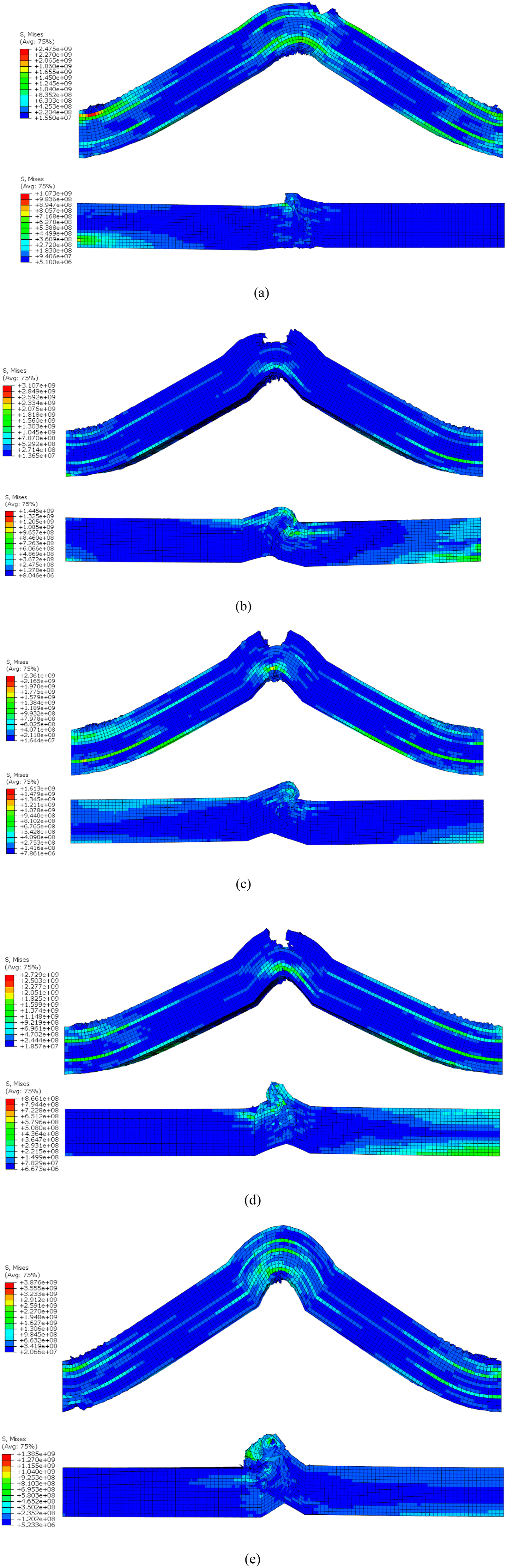
The observed disparities stem from the fundamental differences in axial rigidity and stability modes between the two stacking sequences. For MD layups, while the balanced layup provides more isotropic-like behavior, it results in a lower macroscopic axial stiffness. Therefore, under compressive loading, these structures are prone to premature global buckling. This triggers global out-of-plane instability, manifesting as a pronounced mid-span bulge. As the load intensifies, localized stresses concentrate at the peak of the deflection, triggering damage propagation that ultimately culminates in catastrophic structural failure.
For UD layups under compressive loading, the 0° plies within the wrinkle intrados are subjected to combined localized bending and shear. The fibers in this region undergo pronounced local bending or micro-buckling, leading to localized crushing and shear failure. Due to the severe fiber curvature at the wrinkle trough, stress is highly concentrated; once the local compressive stress exceeds the material’s longitudinal compressive strength, the wrinkle region undergoes premature strength failure. This culminates in a failure mode characterized by localized crushing and rupture confined to the wrinkle site.
The failure mechanisms under static compressive loading exhibit a fundamental divergence from those observed under tension. In UD layups, failure at the wrinkle site is collectively governed by coupled fiber and matrix compressive failure modes. Due to a lack of lateral support, the wrinkle intrados becomes highly susceptible to localized micro-buckling. Conversely, MD layups benefit from the lateral confinement provided by the 90° and 45° plies, which significantly enhances the fibers’ resistance to instability. Consequently, failure in MD layup is dominated by global buckling-induced collapse, demonstrating superior structural stability.
Analysis of stress-displacement response and ultimate load-carrying capacity under static compression
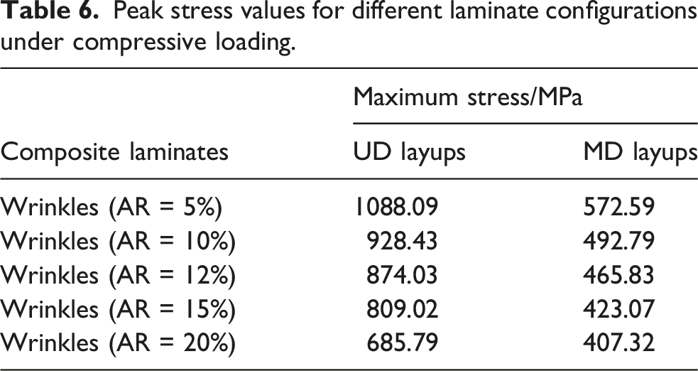
A synthesis of the data in Figure 17 and Table 6 demonstrates that under compressive loading, MD and UD layups exhibit analogous trends in load-carrying capacity and displacement response. Specifically, the UD configuration sustains higher peak stresses but suffers from limited failure displacement. Conversely, the MD layup yields lower ultimate stresses but facilitates significantly extended displacement prior to total rupture. The governing mechanisms behind these phenomena are consistent with the trends observed under tensile loading. Stress-displacement response of wrinkled laminates under compressive loading: (a) multidirectional configuration; (b) unidirectional configuration. Peak stress values for different laminate configurations under compressive loading.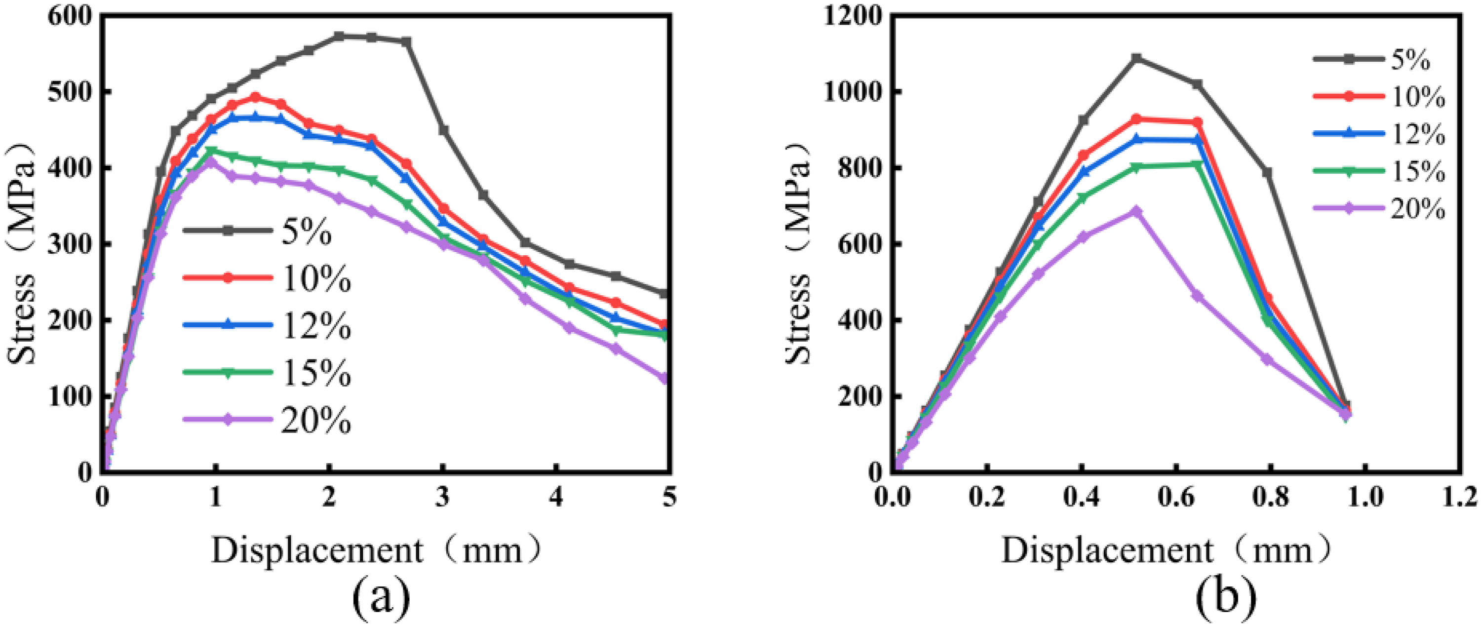
To gain a deeper theoretical understanding of the observed graphical variations, this study directly correlates the macroscopic mechanical responses and localized damage evolution processes with the 3D Hashin model discussed above. A comprehensive analysis of the load-displacement curves in Section 3.3 (Tension, Figure 14) and Section 4.3 (Compression, Figure 17), alongside the corresponding stress contour plots (Figures 7–13, 15, and 16), reveals that the nonlinear characteristics and abrupt load drops in the macroscopic curves coincide precisely with the localized surge of internal stresses within the wrinkled region. According to Hashin’s theoretical formulations, the corresponding failure criteria are strictly triggered once the localized complex strain/stress fields at the wrinkle amplify to reach the damage initiation threshold. As shown in the stress contours in Figure 18, the stress concentration in the wrinkle-sensitive zone directly drives the evolution of state variables (such as SDV8 representing fiber compression and SDV10 representing matrix compression), which is numerically manifested as the rapid expansion of red damage zones. Fiber and matrix compression.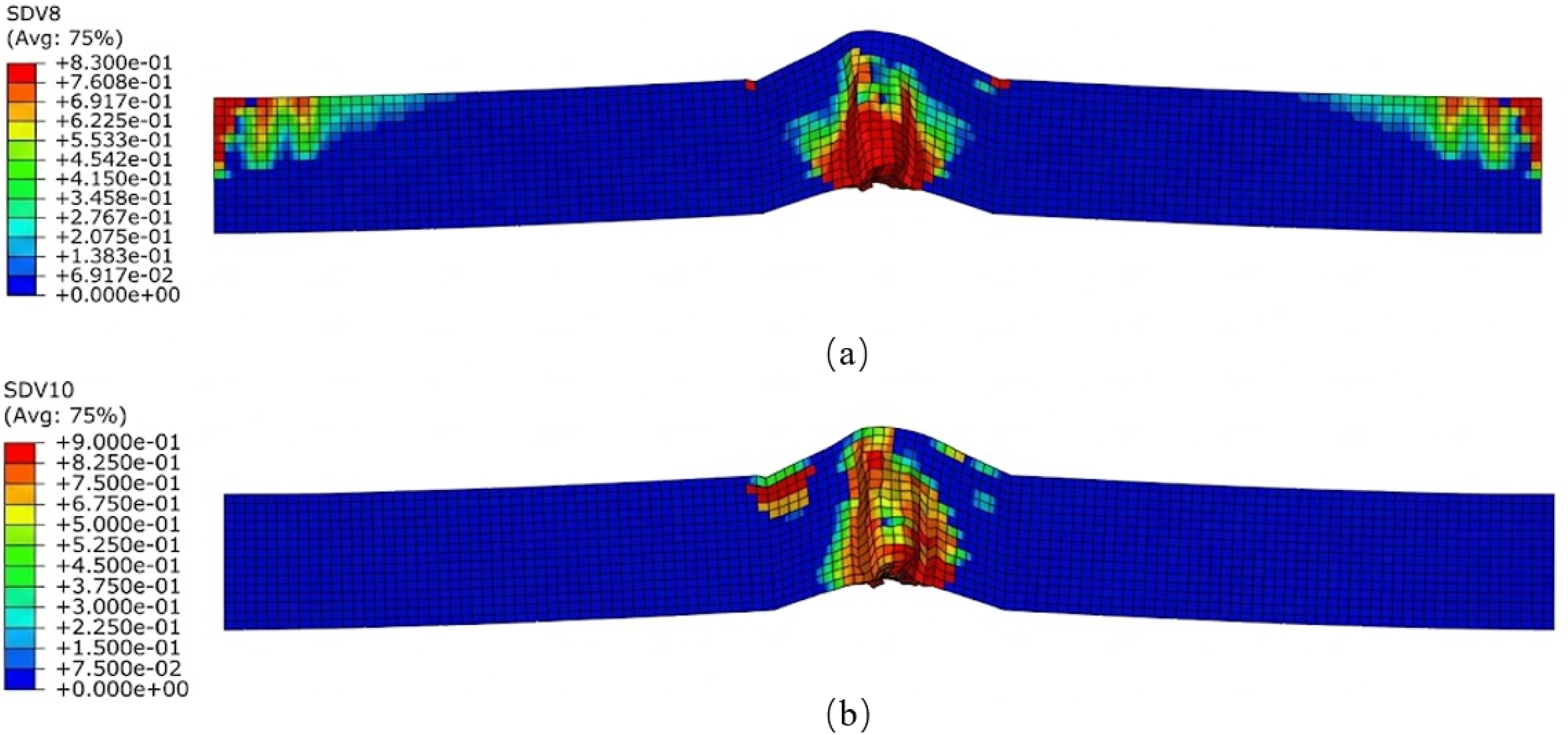
Numerical parametric study on the influence of stacking sequences on local 3D stress tensors
To explicitly bridge the gap between the macroscopic stress distribution and the microscopic damage initiation, a rigorous component-wise stress analysis was conducted. While the previously discussed von Mises equivalent stress contours effectively illustrate the global load-transfer paths, the highly anisotropic failure of CFRP laminates within the parameterized full-thickness out-of-plane wrinkle (OPW) benchmark is fundamentally dictated by the localized three-dimensional stress tensor. Therefore, the six independent stress components (σ11, σ22, σ33, τ12, τ13, τ23) of the critical elements just prior to damage initiation were extracted and quantitatively evaluated.
To investigate the morphological sensitivity of the defects, the local stress tensors were first compared for the multidirectional layups across different wrinkle geometric severities. Figure 19 presents the absolute stress magnitudes at the critical wrinkled regions for wrinkle ratios of 10% and 12%. Comparison of the six independent stress components prior to damage initiation for the multidirectional layups under different OPW geometric severities (wrinkle ratios of 10% and 12%).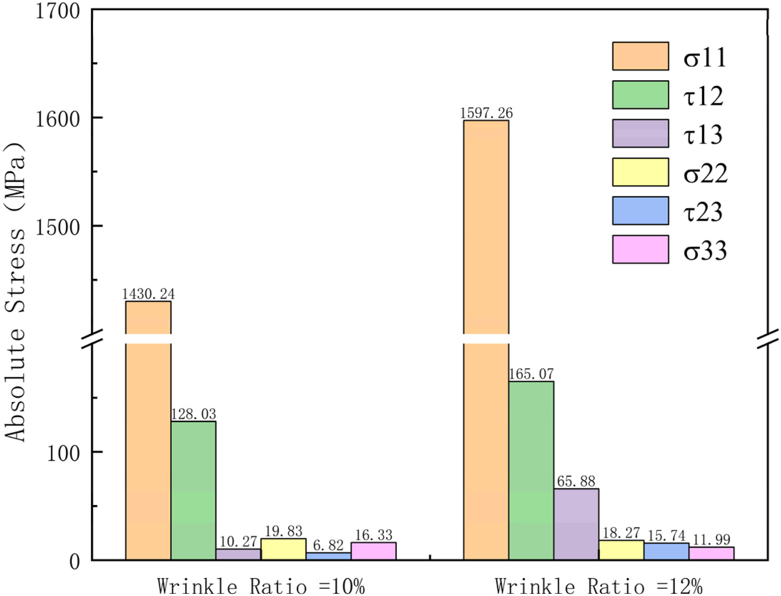
As shown in Figure 19, while the principal load-bearing component σ11 remains dominant, an increase in the geometric severity of the OPW dictates a noticeable spatial decomposition of the load. Specifically, steeper geometric deviations (wrinkle ratio of 12%) significantly amplify the interlaminar shear stress τ13 compared to the 10% baseline. This component-wise evidence demonstrates that increased wrinkle severity promotes the initiation of shear-dominated failure modes by forcing the localized stress tensor into a more complex 3D state.
To further isolate and evaluate the coupling effects of layup and wrinkling, a comparative analysis was performed between different stacking sequences under a fixed geometric defect (wrinkle ratio of 10%). Figure 20 explicitly contrasts the local stress components between the unidirectional baseline and the multidirectional layups. Quantitative evaluation of the coupling effects of layup and wrinkling: comparison of the local stress components between unidirectional and multidirectional layups for a fixed OPW geometry.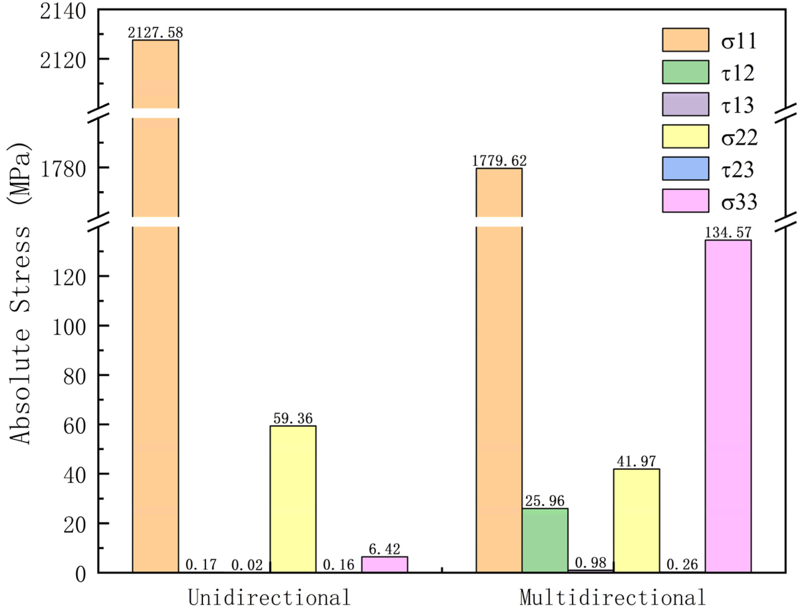
The data reveal a striking, highly localized “stiffness mismatch” phenomenon: in the unidirectional laminate (Figure 20), the load is efficiently carried along the misaligned fibers (σ11 = 2127.58 MPa), with negligible out-of-plane and shear components (e.g., τ12 = 0.17 MPa, σ33 = 6.42 MPa). On the other hand, the introduction of multidirectional stacking sequences creates severe internal constraints between adjacent plies with different orientations. Even under the identical geometric deflection, this pronounced stiffness mismatch triggers a sharp increase in specific stress components. As indicated by the data, the localized out-of-plane normal stress σ33 increases sharply to 134.57 MPa, and the in-plane shear stress τ12 rises to 25.96 MPa.
This component-wise evidence demonstrates the underlying physical mechanism: despite their general structural advantages, multidirectional layups are highly susceptible to localized interlaminar delamination and complex matrix crushing in the presence of out-of-plane geometric defects. This indicates that the predicted progressive damage response is governed by the combined effects of OPW morphology and laminate architecture.
Comparative analysis of static tensile and compressive responses and the influence of stacking sequence
A comparison between Table 5 and Table 6 reveals a distinct performance inversion: for MD layups with identical wrinkle aspect ratios, the ultimate compressive capacity exceeds the tensile capacity. Conversely, for UD layups, the tensile strength is consistently superior to the compressive strength. In MD layups, the limited proportion of 0° plies results in a lower ultimate axial tensile strength. However, the presence of 90° and ±45° layers provides essential shear stiffness and interlaminar confinement, which effectively suppresses localized fiber micro-buckling under compression, thereby enhancing the overall load-bearing capacity.
In UD layups, the alignment of all plies with the principal loading axis maximizes both axial stiffness and load-carrying capacity under tensile regimes. In contrast, under compressive loading—particularly in the presence of wrinkle defects—the absence of 90° and 45° plies to provide lateral support and shear constraint significantly heightens the susceptibility to structural instability, resulting in premature failure.
While both stacking sequences exhibit distinct ultimate stress levels across different loading conditions, they differ significantly in the magnitude of their performance attenuation during the tensile-to-compressive transition. UD layups suffer a substantial reduction in both load-carrying capacity and stability when switching from tension to compression. In contrast, MD layups maintain relatively marginal fluctuations in peak stress and displacement response, demonstrating superior overall stability. In essence, although the MD layup yields lower absolute peak stresses in either regime, it offers enhanced structural robustness and adaptability across diverse loading states.
Conclusion
In this study, a numerical evaluation framework based on the 3D Hashin failure criteria and a progressive stiffness degradation strategy was developed and implemented through a custom VUMAT subroutine. The numerical findings specifically cover the coupling effects of laminate architecture and parameterized out-of-plane wrinkle (OPW) geometry, with aspect ratios ranging from 5% to 20%, under static tensile and compressive loading conditions. The specific scope of the numerical findings explicitly covers the coupling effects of laminate architecture and parameterized out-of-plane wrinkle (OPW) geometric characteristics (with aspect ratios ranging from 5% to 20%) under static tensile and compressive loadings. The synthesized key findings are as follows: (1) Defect Severity and 3D Stress Coupling Mechanisms: The wrinkle aspect ratio is the key parameter governing material reliability. Quantitative evaluation of the independent stress tensors reveals that increasing OPW severity markedly increases local stress concentrations. Specifically, the pronounced interlaminar stiffness mismatch in multidirectional layups, coupled with the geometric deflection of the OPW, triggers an extreme localized surge in the out-of-plane normal stress (σ33) under compressive loading. This component increases by nearly a factor of 20 compared to the unidirectional baseline, reaching 134.57 MPa, accompanied by elevated in-plane (τ12) and interlaminar (τ13) shear stresses. This clarifies the underlying mechanical mechanisms of complex matrix crushing and localized delamination. (2) Stacking Sequence and Loading Mode Dependencies: Unidirectional laminates achieve higher ultimate loads, particularly under tension, but are highly susceptible to severe stress localization and abrupt brittle fracture. Conversely, multidirectional layups exhibit an effective stress-redistribution mechanism across plies. While yielding lower axial strength, they demonstrate superior damage tolerance and structural stability, providing more consistent performance across varying loading states (with compressive ultimate stress frequently exceeding tensile capacity).
These numerical findings provide further insight into composite damage mechanisms. By explicitly correlating the macroscopic load-bearing degradation with the microscopic localized 3D stress surges (σ33, τ13), this study bridges the gap between theoretical failure criteria and complex structural responses driven by manufacturing defects. The validated numerical framework provides a highly reliable predictive methodology for the defect-tolerance design of composite structures.
While this study elucidates fundamental failure principles via idealized full-thickness OPW models, actual wrinkles formed during manufacturing (e.g., vacuum infusion) frequently exhibit asymmetry due to rigid mold constraints. Future research will focus on asymmetric wrinkle models and the introduction of fatigue damage evolution algorithms—specifically targeting compressive fatigue loadings—combined with Digital Image Correlation (DIC) experiments to further investigate the long-term reliability of defective composite components.
Footnotes
Acknowledgments
This work was supported by the Science and Technology Project of China Huaneng Group [grant number HNKJ24-H100].

Author contributions
Funding
The authors disclosed receipt of the following financial support for the research, authorship, and/or publication of this article: This work was supported by the Huaneng Power International; HNKJ24-H100.
Declaration of conflicting interests
The authors declared no potential conflicts of interest with respect to the research, authorship, and/or publication of this article.
Data Availability Statement
The data that support the findings of this study are available on request from the corresponding author.