
Abstract
Enhancing the fracture toughness of the metal–resin interface is essential for improving the overall performance of fiber metal laminates (FMLs). This study is the first to propose to utilize the characteristics of the metal-resin interface as a weak interface and construct a bio-inspired suture structure at the interface to improve the interface fracture toughness. Experimental results demonstrate that the bio-inspired suture structure forms a mechanical interlock at the interface, dissipates more energy under loading, and impedes crack propagation. In test specimens, the critical strain energy release rate (G IC ) reached 4.05 kJ/m2 when the suture’s minor axis length is 3.0 mm and the offset angle is 25°. Therefore, the construction of bio-inspired suture structure at the interface proposed in this study has great application potential for FMLs, which provides a new idea for improving the fracture toughness of metal-polymer interface.
Keywords
Introduction
Fiber metal laminates (FMLs) are a kind of interlaminar hybrid composite material which is made of metal sheet and fiber composite material after plying and curing under certain pressure and temperature.1,2,3 FMLs are considered ideal lightweight structural materials due to their high specific strength, high specific stiffness and excellent fatigue resistance.4,5,6 Compared to aluminum alloys, FMLs exhibit superior fatigue properties and are more cost-effective than pure fiber reinforced composites. More than 400 m2 of FMLs are used in the upper fuselage of the Airbus A380, resulting in a weight reduction of over 25% compared with conventional structural materials. 7 Their application at the leading edge of the vertical and horizontal stabilizers has also reduced structural weight by 20% relative to the original design.8,9 FMLs have broad application prospects in aerospace, automobile, military and other fields. 10
FMLs consist of a complex interface system consisting of fiber-polymer interface and metal-polymer interface, and the metal-polymer interface is usually considered to be a weak interface. 11 The quality of metal-polymer interface composite determines the strain transfer between the metal and the fiber layers, which in turn affects the overall performance of FMLs.12,13,14 In recent years, many researchers have conducted extensive research on how to enhance the interfacial bonding strength between the fiber and metal layers. Chen et al. 15 treated the stainless steel foil with six surface treatment methods, such as silicon carbide sandpaper grinding, cold spraying and laser scanning. Compared with the untreated stainless steel foil, the interfacial bonding strength increased by 210.32%. Jiang et al. 16 employed a new rare earth surface modification technique, creating chemical bonds between titanium and PEEK resin with cerium, which significantly improved the interface shear strength, bending strength, and interlaminar shear strength of the CF/PEEK-Ti laminate. Ji et al. 17 deposited multi-walled carbon nanotubes (MWCNTs) on the surface of a titanium sheet by electrophoresis to construct a micro-nano layer between the titanium sheet and the PEEK layer. The interlaminar shear strength of CF/PEEK-Ti laminates increased by 47.8% compared with that of specimens with only surface sandblasting. Wang et al. 18 reported notable improvements in the interfacial mechanical properties of FMLs by incorporating MWCNTs of different diameters into PI. Wang et al. 19 successfully constructed a biomimetic micro-nano composite structure at the metal-polymer interface of FMLs by imitating the toe-end structure of tree frogs. These works provide new methods and theoretical basis for the interface research of FMLs.
Strength and toughness are two key indicators that determine the mechanical properties of materials.20,21,22 High strength of material is often accompanied by low toughness. FMLs not only need certain interface strength to transfer load, but also need certain toughness to inhibit crack propagation and absorb energy to adapt to complex stress environment. The research of scholars mainly focuses on enhancing the interfacial bonding strength of FMLs, but there are few studies on the interfacial toughness. For instance, Hua et al.
23
studied the interlaminar fracture toughness of GLARE laminates with varying fiber orientations. Xiaopeng Wu et al.
24
used cold welding to spot weld the woven metallic titanium fabric (WMTF) on the surface of TC4 plate. By adjusting the spatial distribution of the weld spots, they significantly enhanced the fracture toughness of the Ti/CFRP laminate. Compared with plain laminates, the mode I fracture toughness was increased by 276%. Inspired by the structure of pangolin scales, Xiaopeng Wu et al.
25
constructed a multiscale texture interface via the electrical sparks lasing process, which increased the mode I fracture toughness G
IC
of Ti/CFRP laminates by 283.62%. Since ancient times, nature has been the source of various technical ideas, engineering principles and major inventions of human beings.
24
After long-term natural selection, many organisms have evolved microstructures
26
with special functions according to the needs of the natural environment, making them both strength and toughness while meeting specific functions.27,28,29 Woodpecker beaks, tortoise shells, mantis shrimps, shells, mammal skulls, etc.30,31,32,33,34,35,36 all show good strength and toughness, as shown in Figure 1. These biological structures provide new opportunities for the design of new materials.
37
The ability to guide and deflect cracks is the basis for the strength and toughness of these materials, which is only possible when the interface is weaker than the building block itself.
38
The suture interface is one of the common structures in the biological world.39,40 The suture increases the complexity of crack propagation by guiding the crack growth path, so as to achieve the purpose of toughening.
41
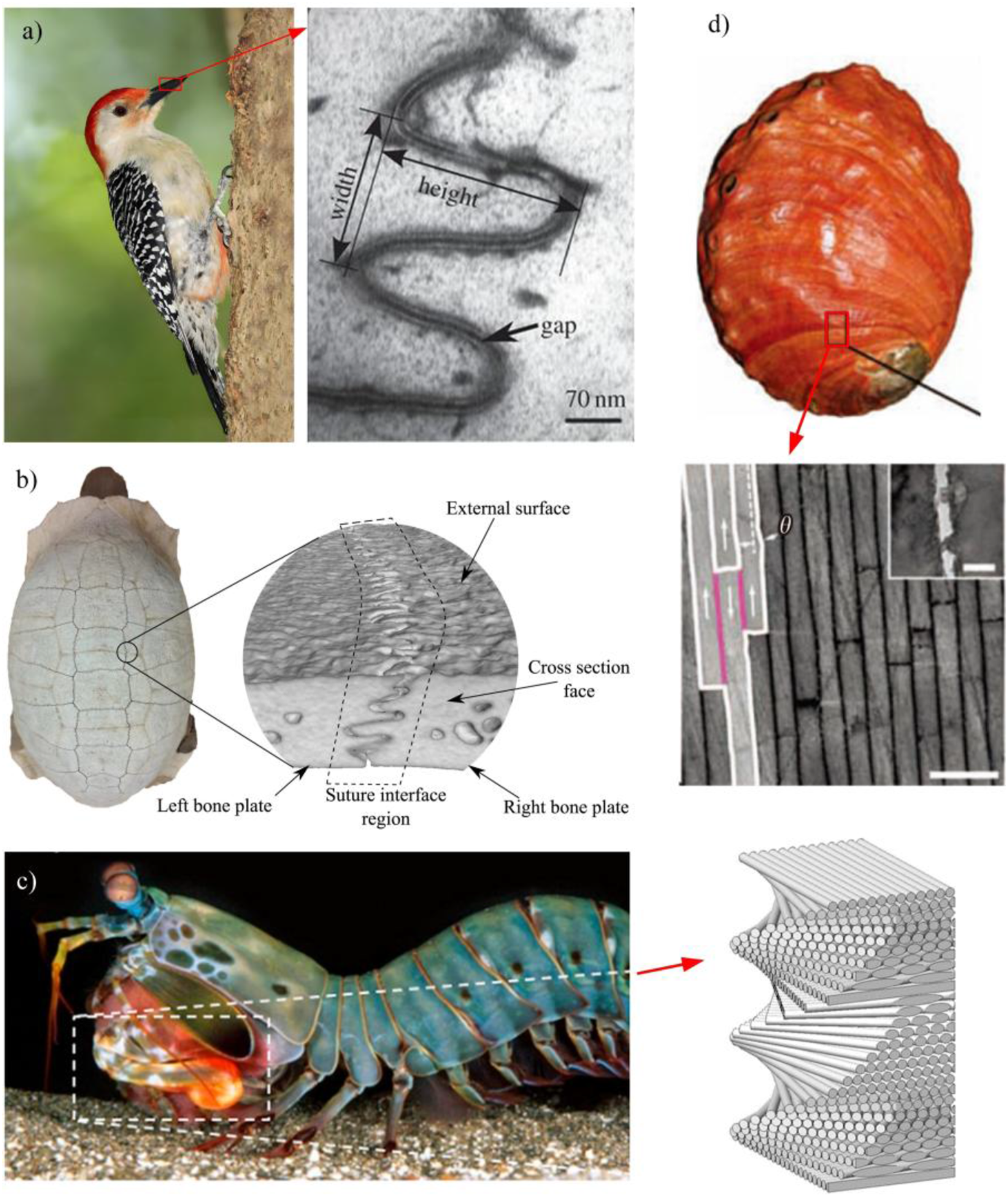
Recently, a unique suture structure was identified in the elytra of the diabolical ironclad beetle, enabling the beetle to withstand extreme compressive forces, such as being run over by a car, without sustaining damage. 42 Therefore, we use the characteristic that the metal and polymer interface of FMLs is a weak interface to construct a bionic ironclad beetle’s suture structure at the interface to enhance the interface fracture toughness.
In summary, in view of the disadvantages that complex interface systems bring to the overall performance and large-scale application of FMLs, in this paper, inspired by the suture structure of the elytra of the ironclad beetle, the characteristics of the metal and polymer interface as a weak interface are utilized to construct a bio-inspired suture structure at the interface of FMLs to improve the interface fracture toughness. In this study, different size parameters of the suture structure were designed, and the influence of different size parameters on the fracture toughness of the structure was studied. The distribution of the strain field of the specimen during the experiment reveals the mechanism of the size parameters on the fracture toughness of the suture structure.
Experimental
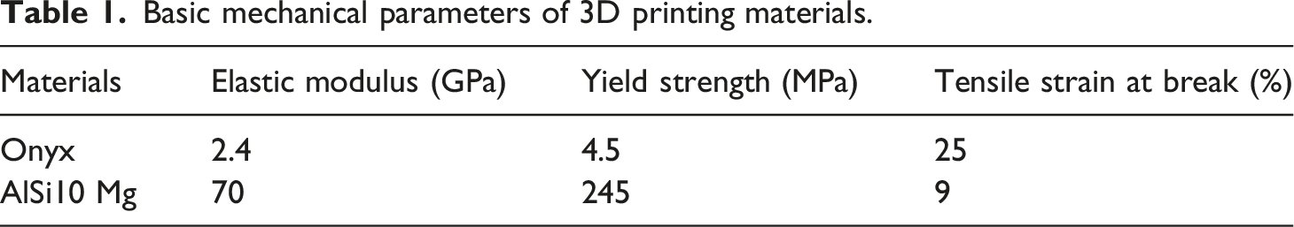
Materials
Basic mechanical parameters of 3D printing materials.
Structural Design and Preparation of Specimens
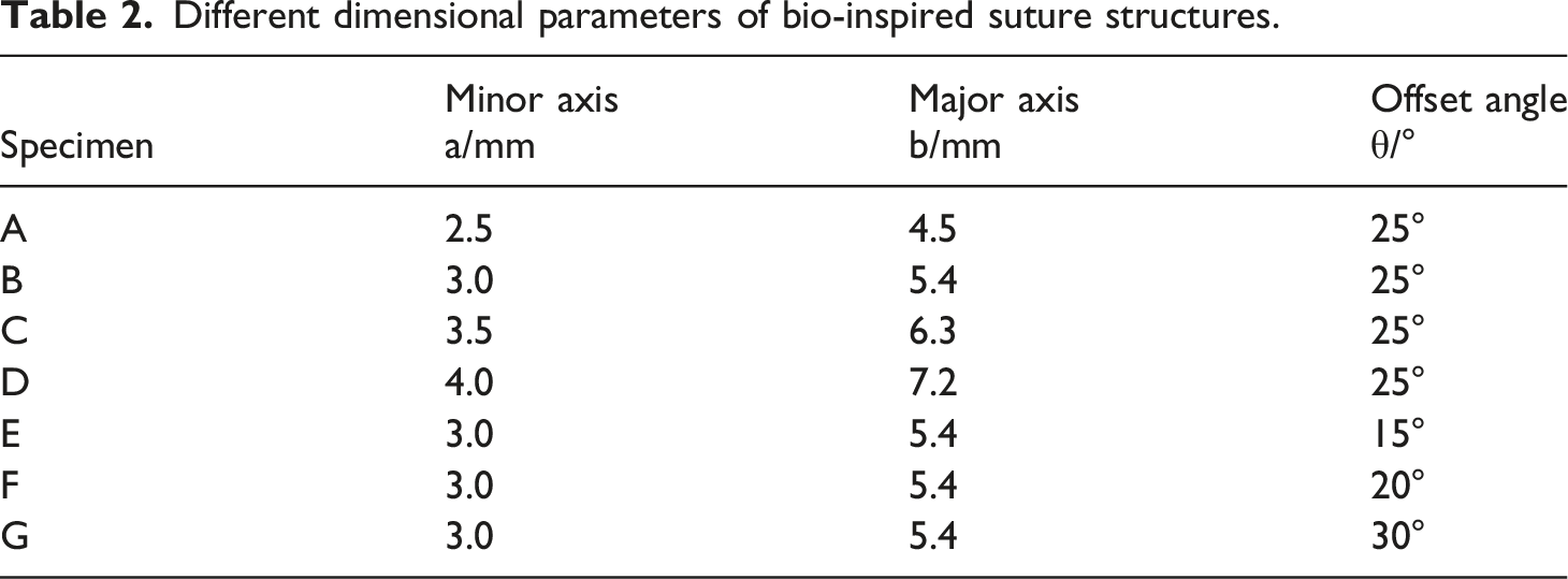
There is a special diabolical ironclad beetle living on the west coast of North America that can withstand an average load of 133 ± 16 N (about 39,000 times its body weight), while other beetles can only withstand an average peak load of less than 68 N. There is a special suture structure in the elytra of the ironclad beetle. It is precisely because of the existence of this structure that it can achieve uniform stress distribution when subjected to external force, thereby being able to withstand higher loads. The microstructure is shown in Figure 2(a). Inspired by this natural design, the current study applies a similar suture structure at the metal-polymer interface of FMLs to enhance interfacial toughness. According to the characteristics of the suture structure in the elytra of the ironclad beetle, the suture is composed of tangent elliptical arcs, the ratio of the ellipse minor-to-major axis (a:b) of 1:1.8, and the ellipses are connected at a specific offset angle θ0. For the convenience of description, the green region in Figure 2(b) is designated the “head” and the orange region is designated the “neck”. In order to explore the effect of varying suture dimension designs on the metal-polymer interface, this study carried out fracture toughness tests and tensile tests on specimens with four different axial lengths and four different offset angles θ of this suture structure. The different suture dimension designs are shown in Table 2. (a) Optical microscope photo of the cross-sectional structure of the elytra of the ironclad beetle.
42
(b) Simplified model of suture structure and FMLs with this structure. Different dimensional parameters of bio-inspired suture structures.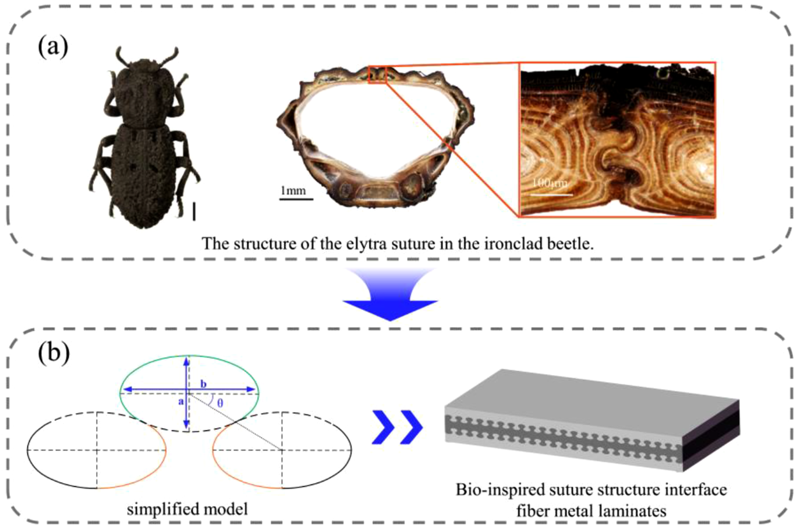
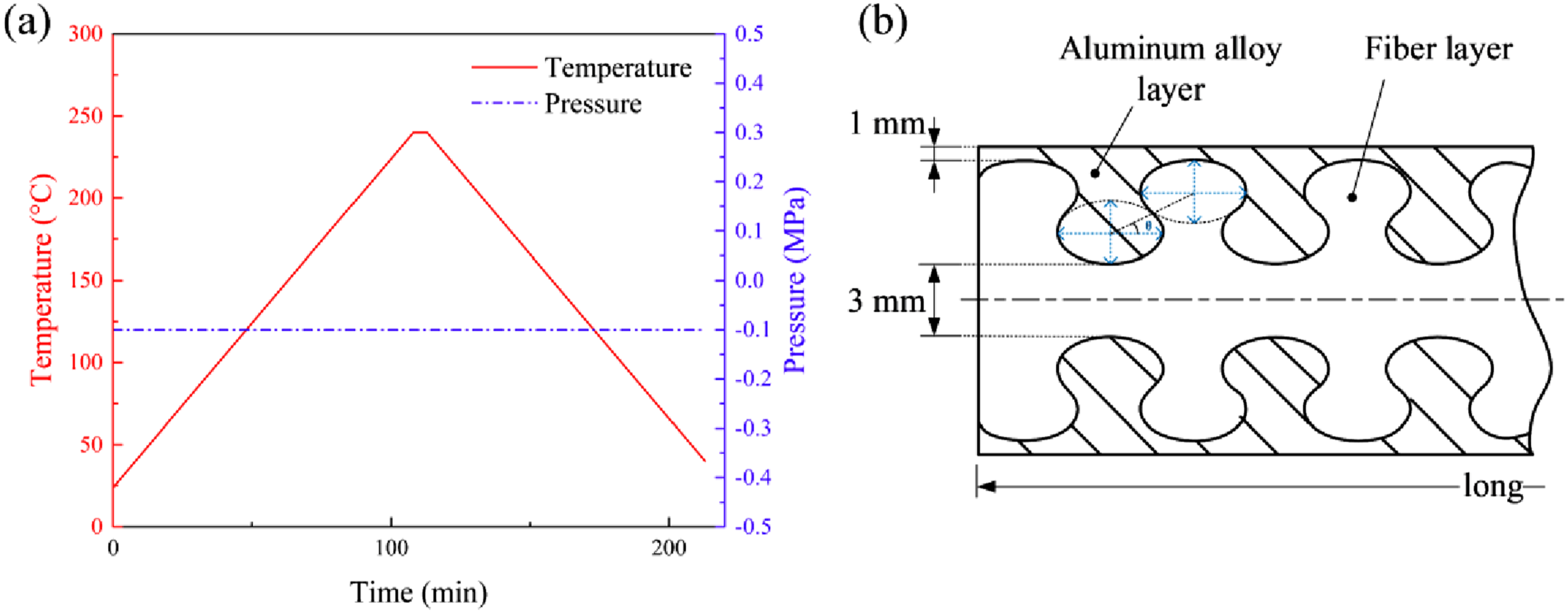
In order to fabricate FMLs featuring the bio-inspired suture structure at the interface, 3D printing technology was used to produce the fiber and aluminum alloy layers, each with corresponding suture structures on their surfaces. The two layers were then joined by insertion, followed by consolidation in an autoclave, as shown in Figure 3. The relationship curves of pressure, temperature and time in the curing process are shown in Figure 4. In order to smoothly insert the two into one, a clearance fit was adopted at the suture structure. In order to obtain a good composite at the FMLs interface, the surface of the aluminum alloy layer was treated. First, the aluminum alloy layer was completely immersed in a NaOH solution with a concentration of 100 g/L, the aluminum alloy surface was corroded for 2 min, and then rinsed with deionized water. Then the specimens were placed in HNO3 solution with a concentration of 100 g/L for 2–3 min, and washed with deionized water.
43
Preparation of FMLs by autoclave. Curing curve and structural dimension relationship of laminates. (a) Relation curve of temperature, pressure and time; (b) Specimen size.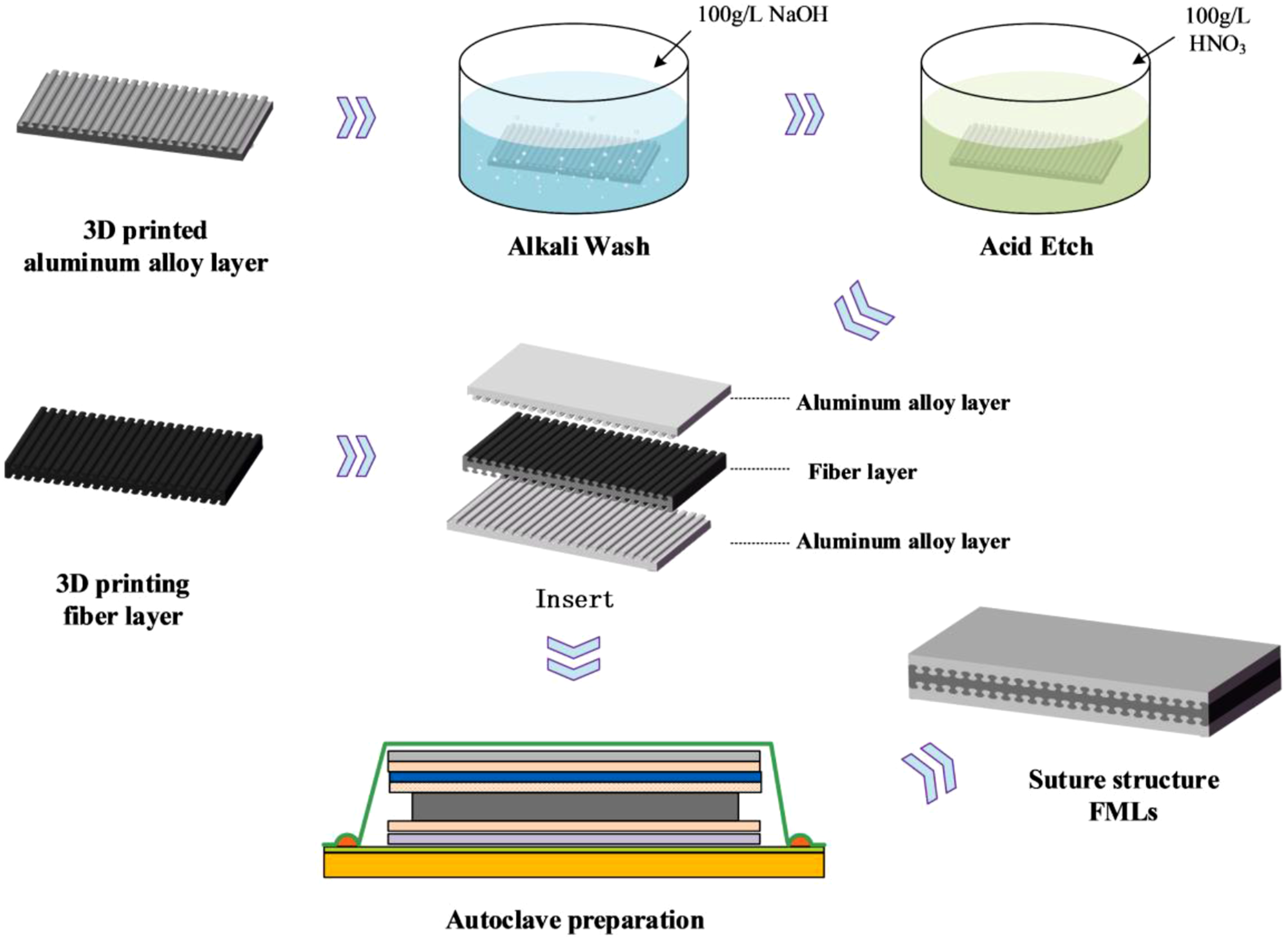
Performance Testing and Characterization
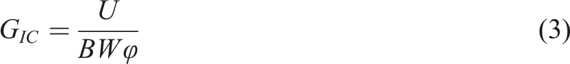
In this study, the fracture toughness of specimens with various minor axis lengths and different offset angles was tested according to the ASTM D5045-14 standard. The critical stress intensity factor (K
IC
) and critical strain energy release rate (G
IC
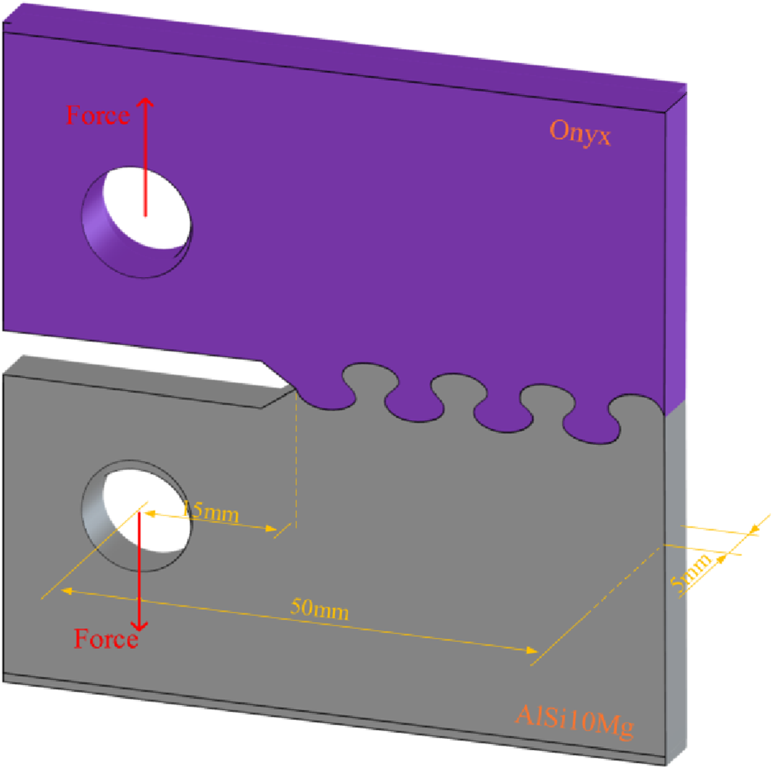
) were calculated, as shown in Equations (1) and (2). Standard specimens with suture structures were 3D printed using Onyx and AlSi10 Mg aluminum alloy powders to compare the influence mechanism of different suture dimension designs on fracture toughness. Then the two are assembled into one and the fracture toughness test is carried out according to the test standard. The specimen dimensions are shown in Figure 5. The fracture toughness tests were performed on a universal testing machine with a maximum load capacity of 1 kN and a crosshead speed of 1 mm/min. At the same time, digital image correlation (DIC) technology was used to record and monitor the changes in the strain field of the specimen during the quasi-static stretching process, and the influence mechanism of suture structures of different sizes on the overall mechanical properties of the specimen was analyzed. The fracture toughness of the suture structure was calculated using the following equations: The specimen dimensions for fracture toughness tests.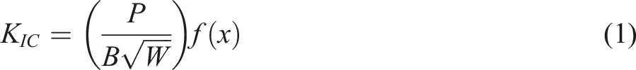

The quasi-static tensile performance tests were performed according to GB/T 1447-2005, with load, displacement, and failure modes recorded for each specimen. The loading speed was 1 mm/min. DIC was used to observe changes in the strain field, allowing comparison of stress transfer mechanisms among the different design variants. Five specimens were tested for each size configuration.
Results and Discussion
Bio-Inspired Suture Structure FMLs
In this study, FMLs with bio-inspired suture structures at the metal–resin layer interface were fabricated by autoclave processing to evaluate the feasibility of incorporating such suture structures in FMLs. Evenly distributed chopped carbon fibers can be observed on the surface of the 3D printed fiber layer, as shown in Figure 6(a). After acid and alkali washing, the surface of the 3D printed aluminum alloy layer exhibits continuous, uniform, cell-like protrusions, as shown in Figure 6(b). The surface roughness of 3D printed aluminum alloy plate is 3.33 Surface morphology and roughness of 3D printed body. (a) Onyx surface; (b) Aluminum alloy surface before acid and alkali treatment; (c) Aluminum alloy surface after acid and alkali treatment.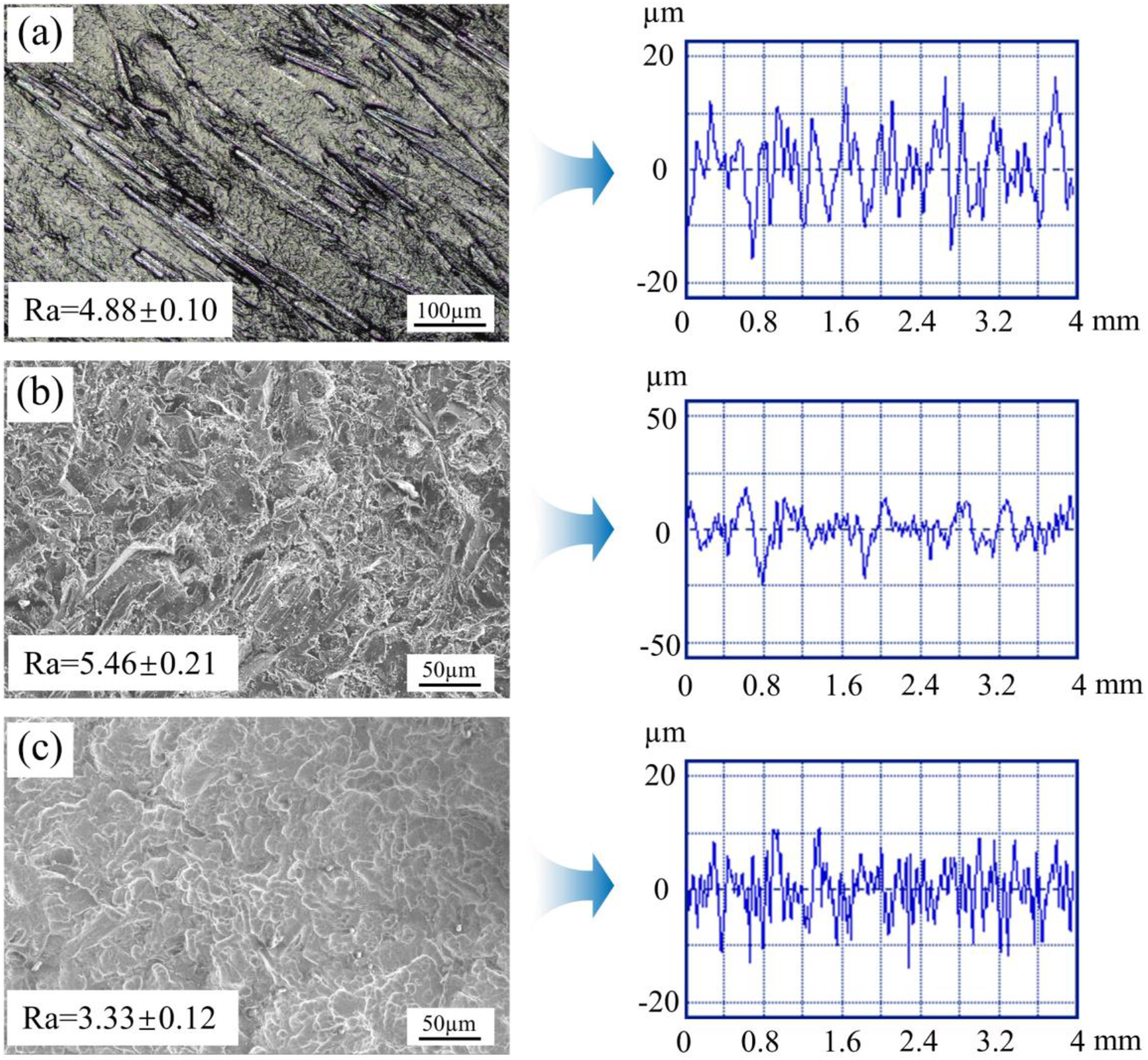
To assess bonding at the metal–polymer interface, element line scanning was performed across the laminate interface (Figure 7(a)). There is an obvious diffusion phenomenon of Al and C elements at the interface of the laminate, and the diffusion distance is about 2 μm, as shown in Figure 7(b). The line scanning data show that the metal-polymer interface of the composite laminates remains well bonded after the addition of the ironclad beetle elytra suture structure to the interface. Consequently, it is entirely plausible to employ bio-inspired suture structures as the interface for FMLs. Composite interface bonding area and EDS spectrum. (a) Interface SEM image; (b) Distribution of elements along the red line.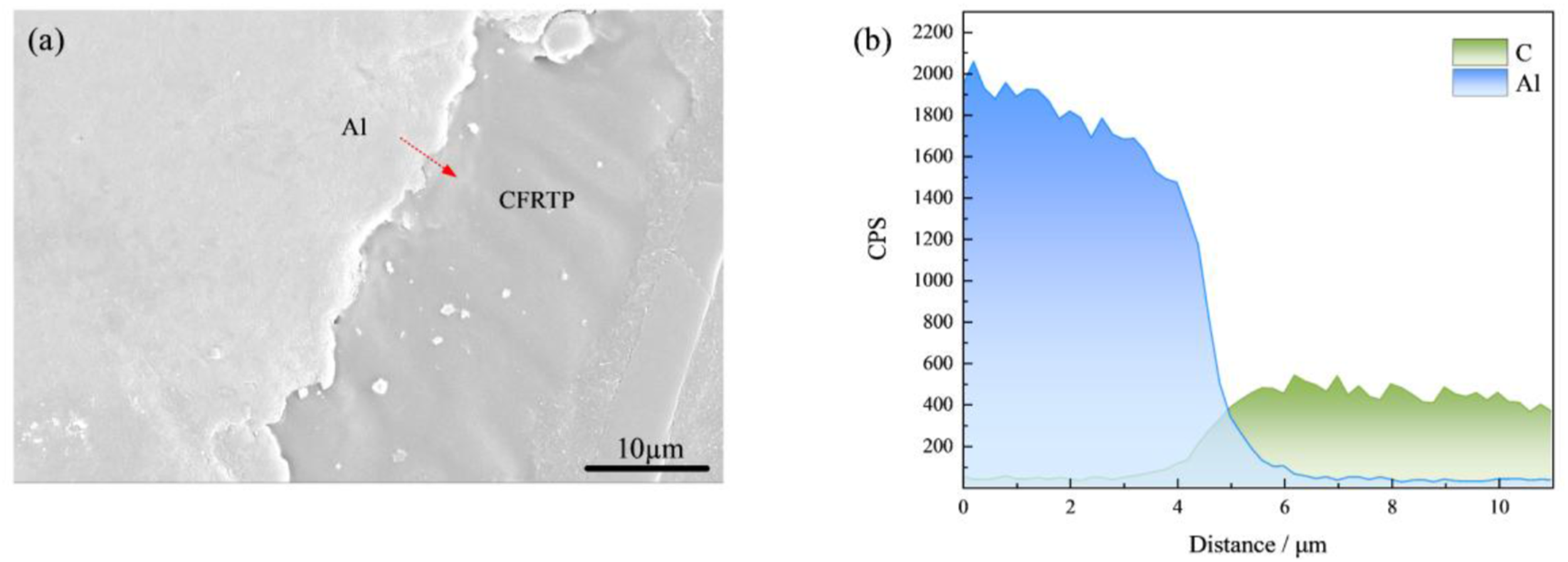
Effect of Different Minor Axis Lengths on the Fracture Toughness of Suture Structures
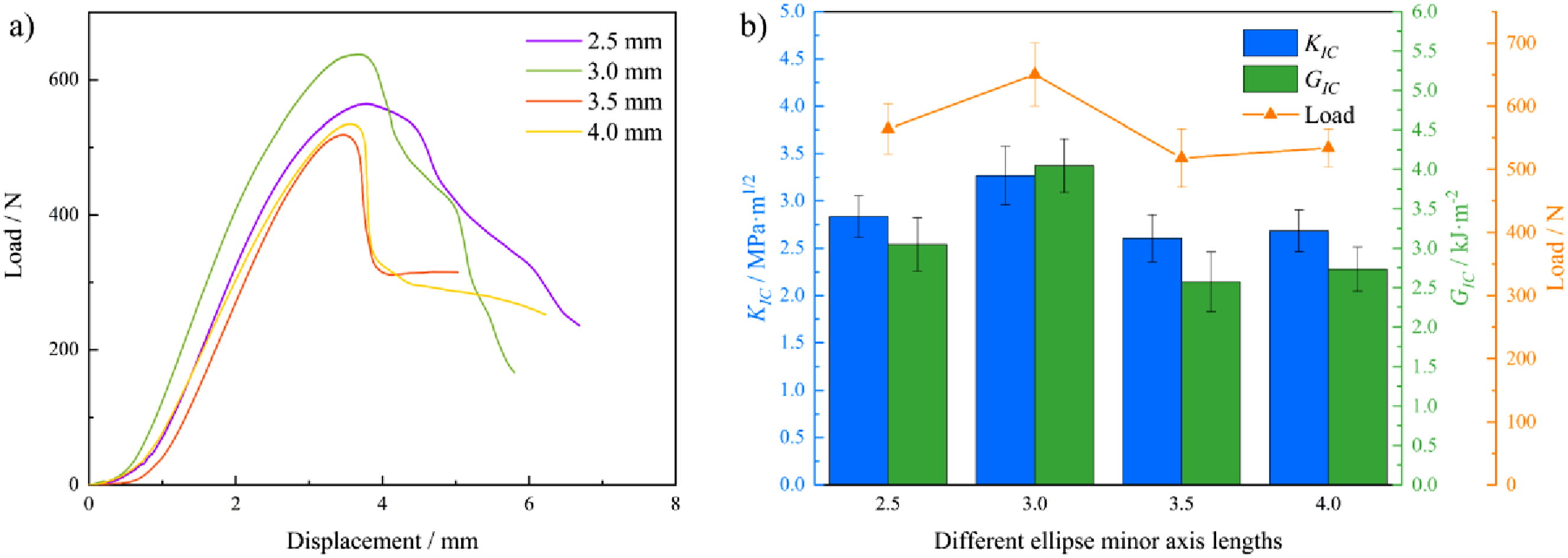
Figure 8 shows the performance comparison of four suture structures with different minor axis lengths. Figure 8(a) shows the load-displacement curves of specimens with four different minor axis lengths. With the increase of the minor axis increases, the peak load on the specimen increases first and then decreases, as shown in Figure 8(b). When the length of the minor axis is 3.0 mm, the peak load that the specimen can withstand is the largest. It can be observed in Figure 8(a) that the specimen with a minor axis length of 2.5 mm has the largest displacement when the peak load is generated, and as the minor axis length increases, the displacement of the peak load gradually decreases. At the start of testing, the nonlinear rise in the load-displacement curve suggests that the suture structure absorbs part of the applied energy initially. No brittle fracture was observed during the test. Correspondingly, both the G
IC
and K
IC
follow a trend of initial increase and subsequent decrease, as shown in Figure 8(b). The G
IC
of conventional FMLs typically ranges from 100 J/m2 to 400 J/m2.
23
However, after adding bionic suture structures of different sizes in this study, the G
IC
of FMLs was between 2000 J/m2 and 4000 J/m2, which is a significant improvement compared with before. Therefore, the experimental results prove that applying the ironclad beetle elytra suture structure to the FMLs interface can significantly improve toughness. Comparison of four suture structures with different minor axis lengths. (a) Load-displacement curves of specimens with different minor axis lengths; (b) Correlation between dimensional design and force, K
IC
, and G
IC
.
In the process of quasi-static tension, Onyx has a lower elastic modulus and lower yield strength than aluminum alloys, making it more susceptible to elastic deformation. Therefore, the deformation mainly occurs on the Onyx side (Figure 9(a)–(d)) in the upper part), while the deformation on the aluminum alloy side remains minimal. In Figure 9, we can observe that the strain of the specimen with a minor axis length of 2.5 mm is concentrated at the head of the suture structure. As the minor axis length increases, the strain gradually transfers to the neck, leading to strain concentration in this region. The initial failure is observed at the location of strain concentration, as shown in Figure 9(e)–(h). The offset angle of these suture structures is 25°, which can produce a good mechanical interlocking effect. Therefore, there is no phenomenon of interlocking structure disengagement. For the specimen with a minor axis length of 3.0 mm, strain is mainly concentrated at the neck, but distribution is relatively uniform. The specimens with minor axis lengths of 3.5 mm and 4.0 mm are more concentrated in the neck strain. When the minor axis length is 3.0 mm, the G
IC
of the specimen reaches a maximum of 4.05 kJ/m2. The strain field (eyy) and failure location during tensile testing of specimens with different dimensions: (a) and (e) 2.5 mm, (b) and (f) 3.0 mm, (c) and (g) 3.5 mm, (d) and (h) 4.0 mm.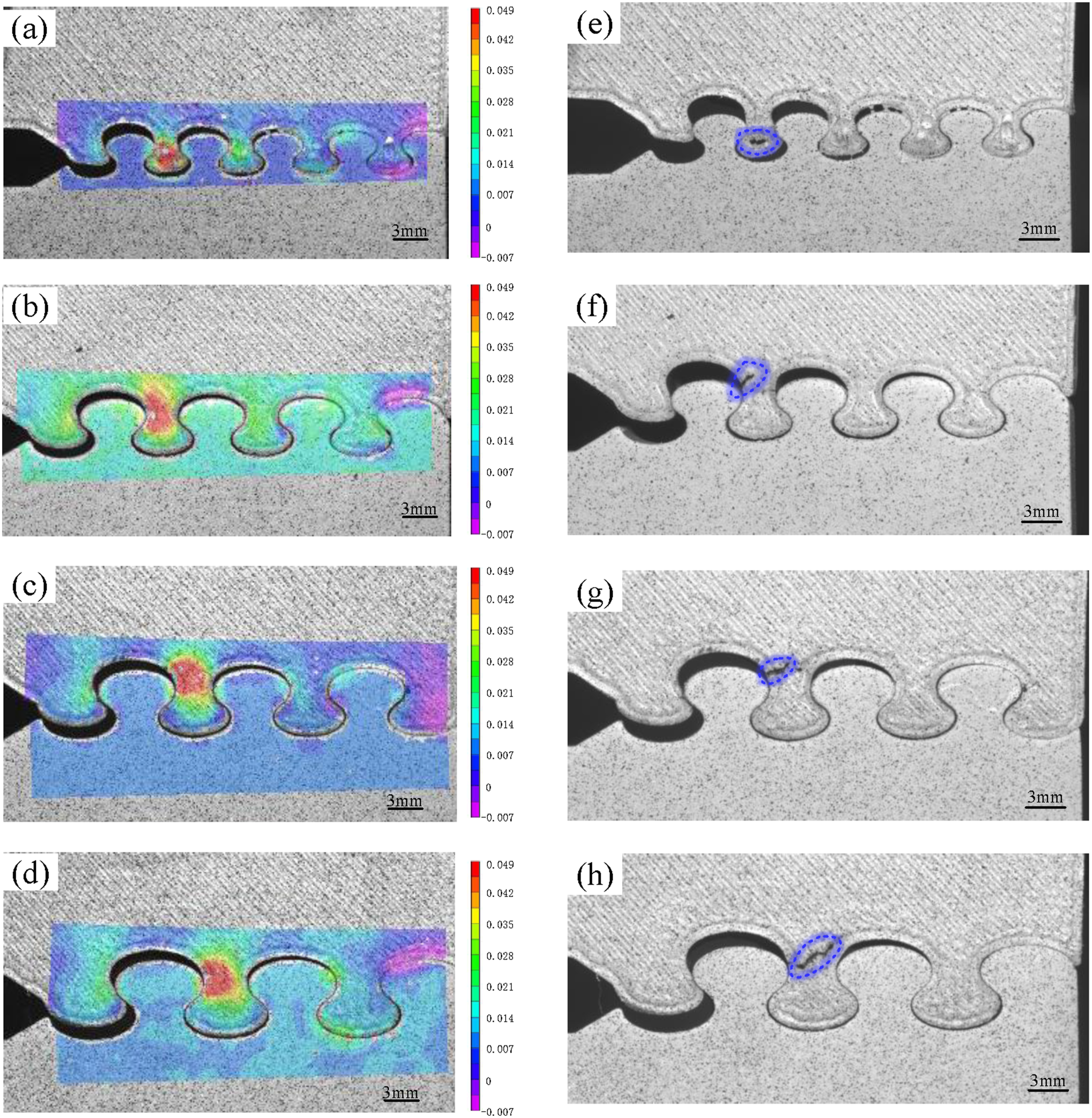
These results indicate that strain distribution in specimens varies according to suture structure size. This size-dependent distribution influences both the peak load and the fracture toughness observed, as shown in Figure 8. The findings suggest that the design size of the specimen is not the larger or the smaller the better. The appropriate size design is conducive to adjusting the position distribution of the strain, which in turn helps to improve the fracture toughness.
Effects of Different Offset Angles on the Fracture Toughness and Tensile Properties of Suture Structures
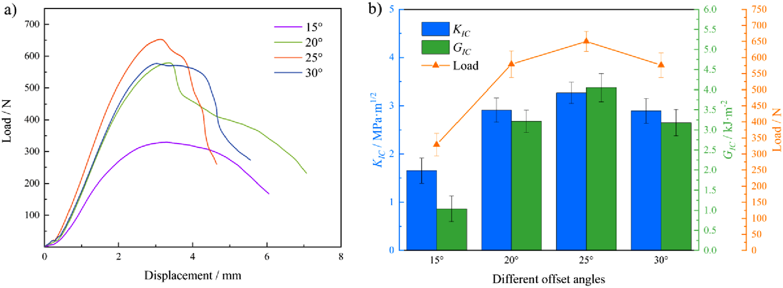
Figure 10 illustrates the impact of four different offset angles on the performance of the suture structure. It can be observed from Figure 10(a) that the displacement difference of the specimens with varying offset angles is largely consistent when the peak load is generated. The specimen with a 15° offset angle exhibits the smallest peak load. As the offset angle increases, the peak load that the specimen with an offset angle of 25° can withstand reaches the maximum and then begins to decrease, as shown in Figure 10(b). No brittle fracture was observed during the experiments. Here we speculate that when the offset angle is small, the mechanical interlocking degree of the suture structure is low, so the peak load that the structure can withstand is lower. With the increase of the offset angle, the degree of mechanical interlocking of the suture structure increases, and its peak load also increases. However, excessive interlocking beyond an optimal point may limit further increases in peak load, a point which will be further analyzed below. In parallel with peak load variations, fracture toughness increases initially and then decreases with increasing offset angle. In summary, a suitable offset angle design is critical for enhancing fracture toughness. At an offset angle of 25°, the fracture toughness of the suture structure reaches its highest value (G
IC
= 4.05 kJ/m2), corresponding to the offset angle found in the elytra of the ironclad beetle. Comparison of structural properties of sutures with different offset angles. (a) Load-displacement curves of specimens with different offset angles; (b)The correlation between offset angle design and force, K
IC
, G
IC
.
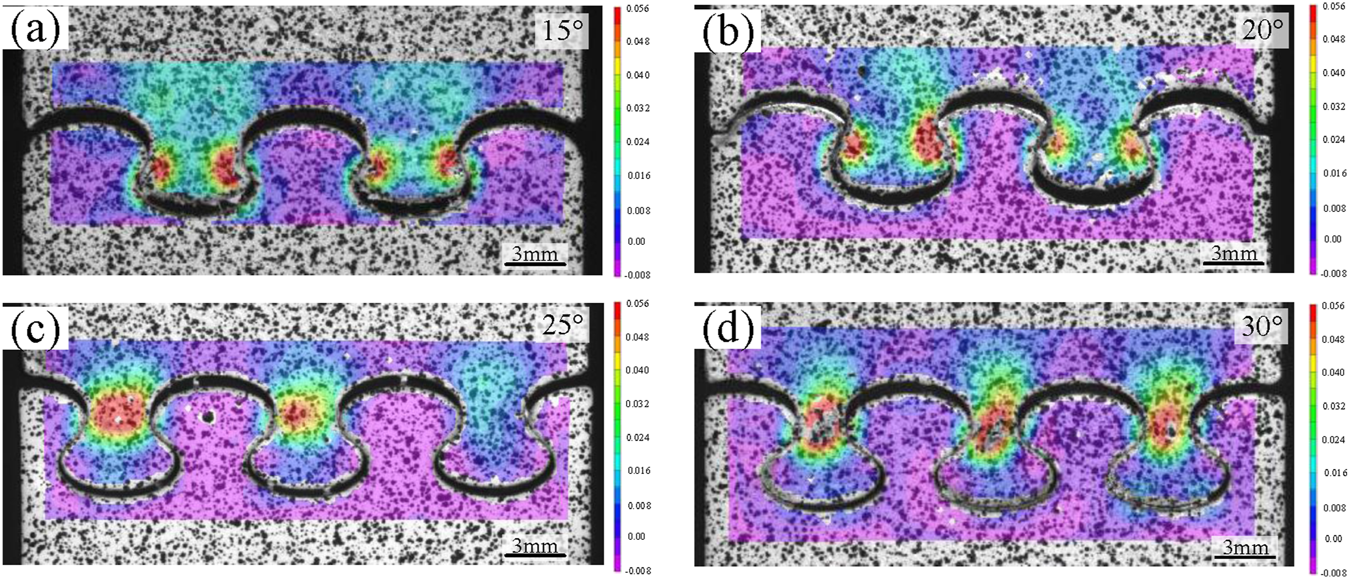
The deformation of the specimens with different offset angles still mainly occurs on the Onyx side, which is consistent with the deformation law during the fracture toughness test of the specimens with different minor axis lengths mentioned above, as shown in Figure 11. For the specimen with an offset angle of 15°, the smaller offset angle results in a lower degree of mechanical interlocking of the suture structure, which makes it appear as the disengagement of the interlocking structure when it fails, but the material itself does not break, as shown in Figure 11(e). With the increase of the offset angle, the degree of mechanical interlocking also increases. When the offset angle is small, the strain of the specimen is concentrated in the transition part of the head and neck of the suture during the quasi-static tensile process, as shown in Figure 11(a). As the offset angle increases, the strain gradually moves toward the neck and becomes more concentrated. For the 20° specimen, strain concentration shifts toward the head of the suture structure, and failure occurs there, as shown in Figure 11(f). When the offset angle is 25°, the strain of the specimen is concentrated at the neck of the suture structure, and the failure of the structure manifests as neck failure in Figure 11(g). At this angle, both the peak load and fracture toughness are maximised. Further increase in the offset angle leads to a narrowing of the structure neck, but the strain is still concentrated in the neck of the specimen structure, as shown in Figure 11(d). This leads to the reduction of the peak load that the specimen can withstand, and the fracture toughness of the suture structure also decreases. This is why the peak load of the 25° specimen in Figure 10(b) reaches the maximum and then begins to decrease. Therefore, adjusting the offset angle modulates the strain distribution within the suture structure, which in turn influences its fracture toughness. When the offset angle is 25°, the fracture toughness of the specimen is the highest. Strain field (eyy) and failure location during the tensile process of specimens with different offset angles: (a) and (e) 15°; (c) and (f) 20°; (d) and (g) 25°; (d) and (h) 30°.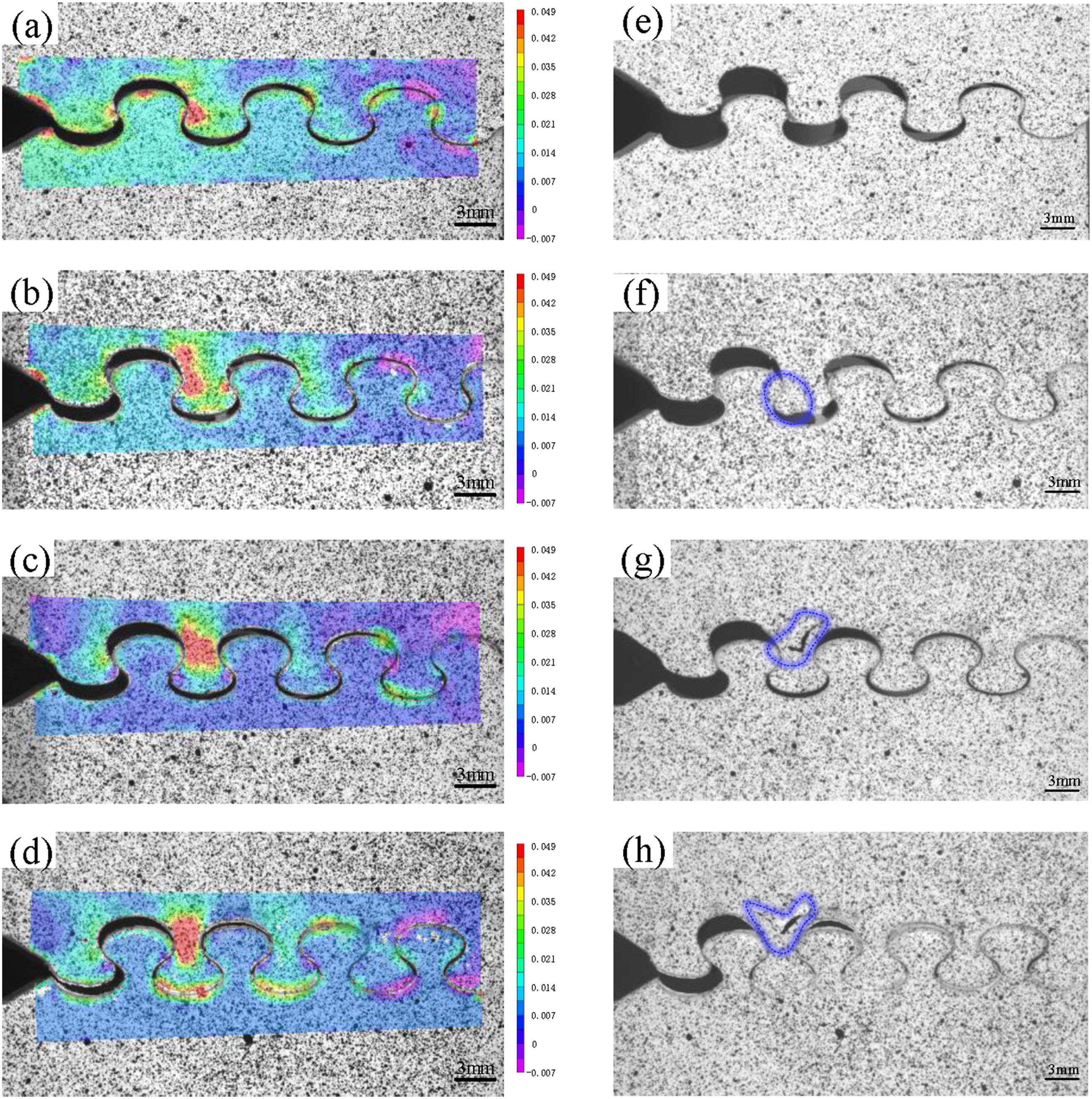
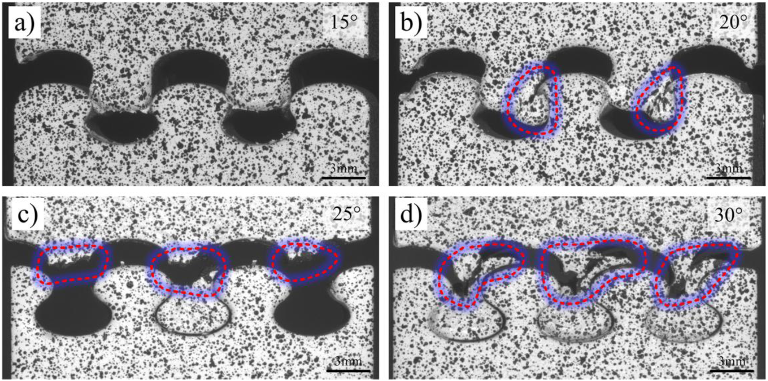
Furthermore, tensile properties at different offset angles were tested, and the load-displacement curves are shown in Figure 12. As the offset angle increases, the peak load follows the same trend: initially increasing, then decreasing, with the highest peak load occurring at 25°. The strain field of the specimen during quasi-static tension is shown in Figure 13. The specimen with an offset angle of 15° had a low degree of mechanical interlocking, the strain was mainly concentrated in the head, and failure was manifested by the head detaching. As the offset angle increases, the strain concentration area of the specimen with an offset angle of 20° begins to move toward the neck, but it still shows head failure, as shown in Figure 14(b). With the further increase of the interlocking angle, the strain of the specimen is completely concentrated in the neck, and the failure is neck failure, as shown in Figure 13(c) and Figure 14(c). When the offset angle is 30°, the strain of the specimen is still concentrated in the neck, as shown in Figure 13(d). However, the width of the neck becomes narrower, which reduces the maximum load that the specimen can withstand. This explains the decrease in peak load after the 25° offset angle, confirming that peak load first increases and then decreases as the offset angle increases. Load-displacement curves of tensile properties test of specimens with different offset angles. Strain field (eyy) during tensile process of specimens with different offset angles: (a) 15°; (b) 20°; (c) 25°; (d) 30°. Failure position of tensile specimens with different offset angles: (a) 15°; (b) 20°; (c) 25°; (d) 30°.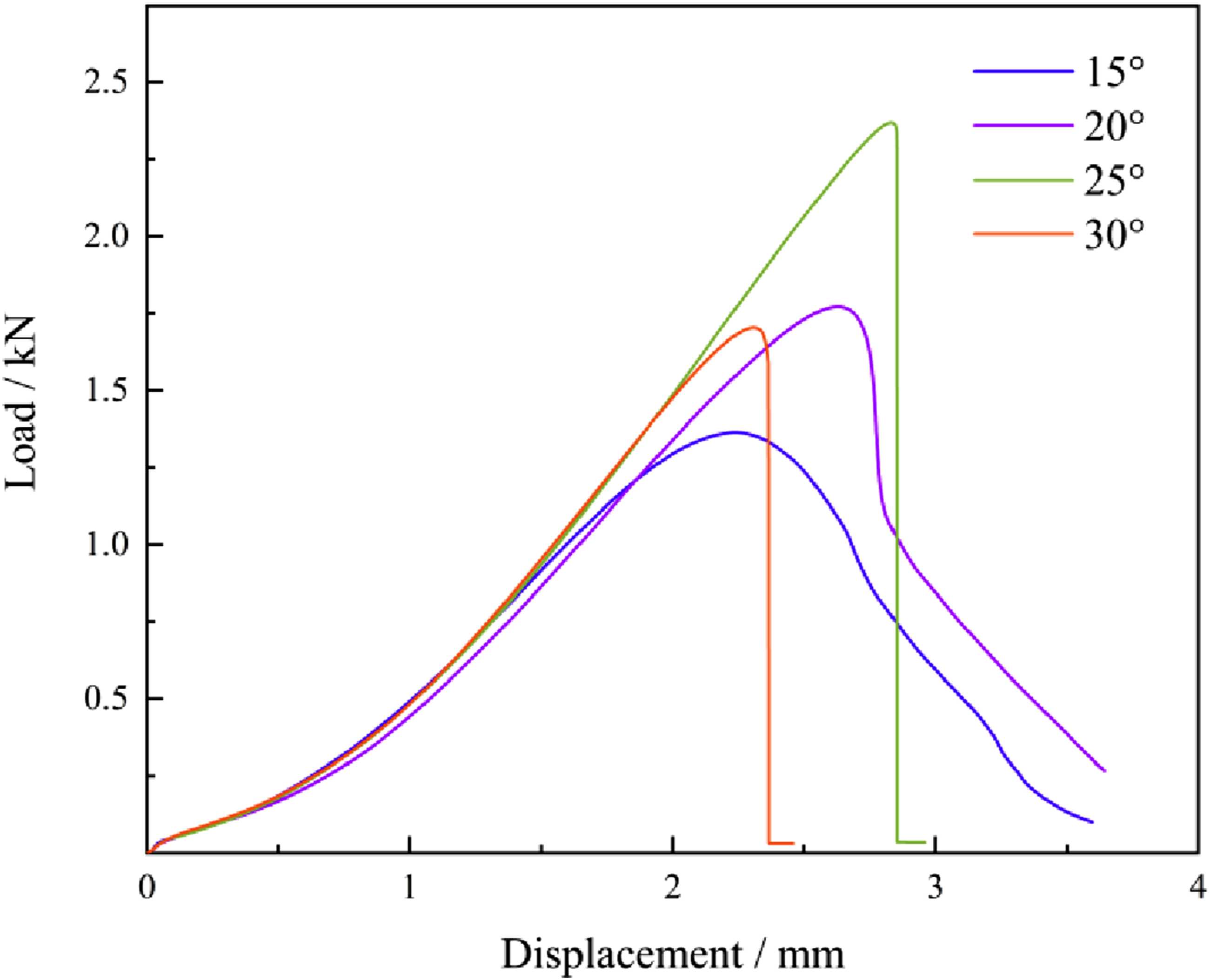
Failure Forms and Analysis of Suture Structure
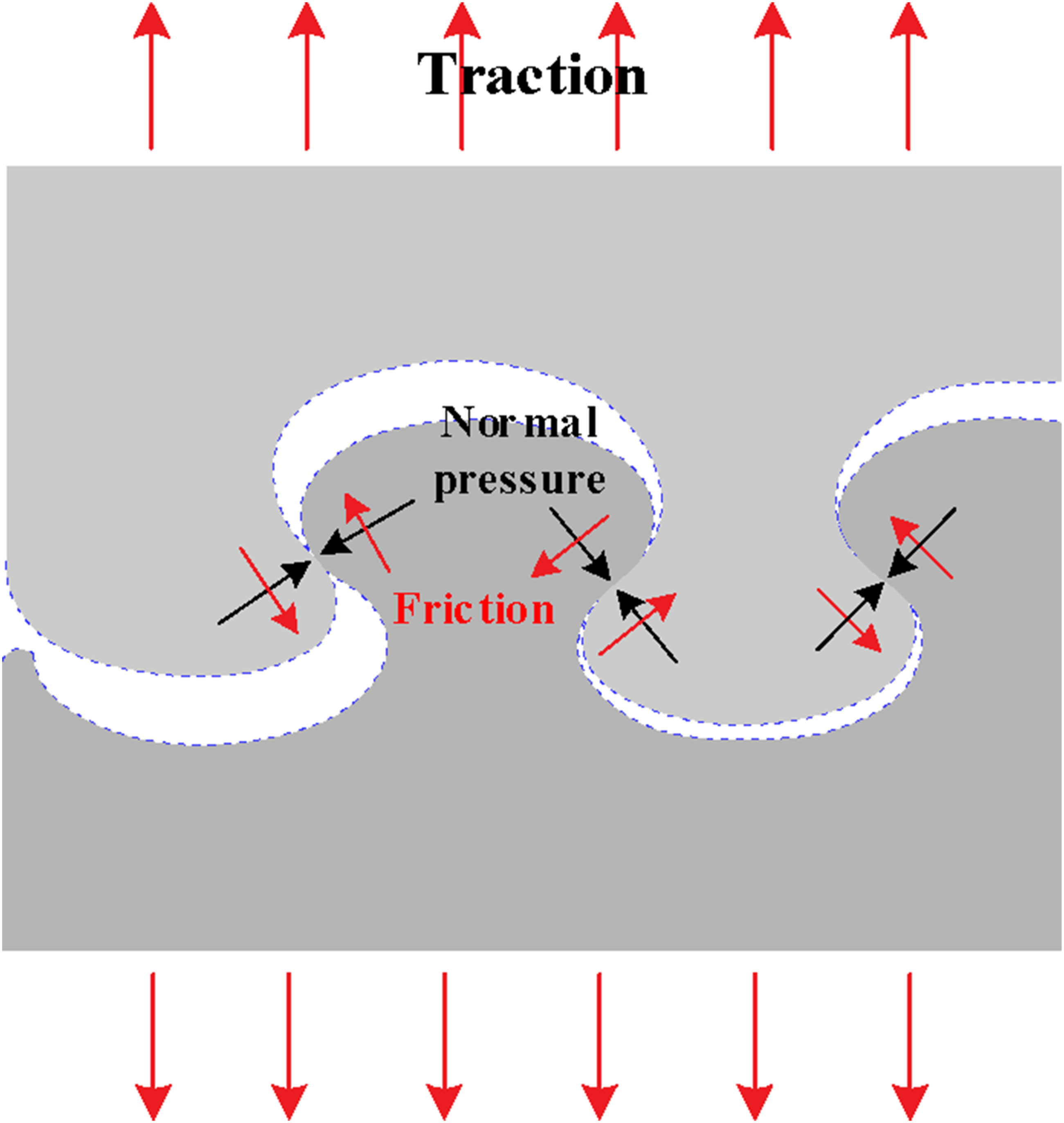
The results of the above experiments indicate that the suture structure primarily exhibits three failure modes: interlocking structure detachment, head failure, and neck failure, as shown in Figure 15. During the fracture toughness test, the contact surface of the suture structure is mainly affected by the combined action of normal force and friction force, as shown in Figure 16. When the offset angle of the suture structure is small, the interlocking structure of the specimen is detached under the action of a smaller force. At this stage, due to the small offset angle, the normal force and friction force of the structure are small, and the specimens are interlocked and disengaged without reaching the material fracture stress. As the offset angle increases, the degree of mechanical interlocking, as well as the normal and friction forces on the contact surface, also increase. Under the combined action of normal force and friction force, the specimen gradually reaches the material fracture stress. At this time, the strain is mainly concentrated at the head of the suture structure, so it manifests as head failure. The offset angle is further increased, so that the suture structure is in a high degree of interlocking state, and the normal force and friction force on the contact surface are further increased. At this time, the strain is completely concentrated on the neck, so it manifests as neck failure. Similarly, when the minor axis length is too small, the load that the specimen head can withstand is also small, which is manifested as head damage. When the minor axis length increases, the size of the specimen head increases, and it can withstand a larger load, and the normal force and friction force on the contact surface of the suture structure increase. The strain of the specimen is concentrated on the neck, which is manifested as neck failure. Failure form of bio-inspired suture structure. Force analysis of the contact surface of the suture structure.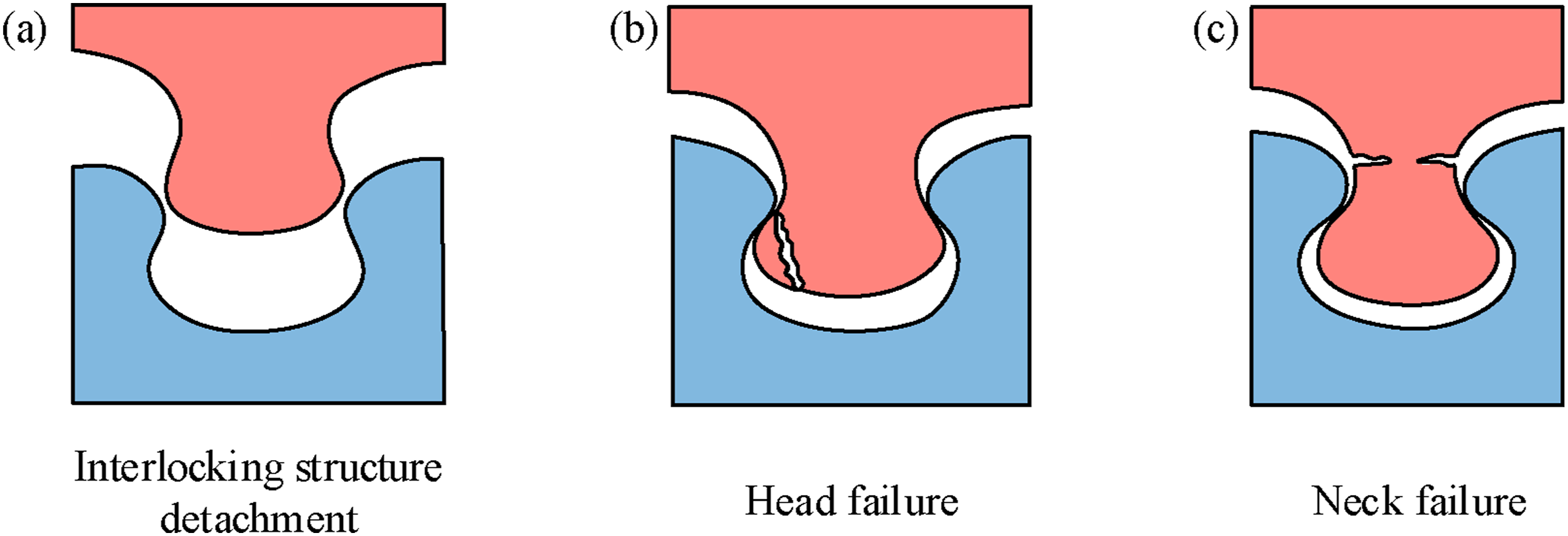
Conclusion
This study constructed a bio-inspired diabolical ironclad beetle elytra suture structure at the metal-polymer interface of FMLs to improve interfacial fracture toughness. FMLs with the suture structure were prepared using an autoclave process, resulting in a substantial improvement in interfacial fracture toughness. Specimens with either a very small or very large minor axis length and offset angle did not achieve optimal fracture toughness. When the minor axis length is 3.0 mm and the offset angle is 25°, the strain of the specimen is concentrated on the neck and distributed more evenly, and the fracture toughness G IC is the highest at 4.05 kJ/m2. The mechanical interlocking effect of the bio-inspired suture structure enables the interface to absorb more energy during loading. In this study, the bio-inspired suture structure provides great potential for improving the interfacial fracture toughness of FMLs. Therefore, the bio-inspired suture structure provides a promising direction for improving the toughness of metal-polymer interfaces in FMLs and offers guidance for addressing other interfacial bonding challenges involving metals and polymers.
Footnotes
Author contributions
Jian Wang: Conceptualization, Funding acquisition, Methodology. Aidong Wang: Data curation, Investigation, Methodology, Writing – original draft. Zijun Ding: Investigation, Methodology. Jianan Liu: Investigation, Project administration.
Declaration of conflicting interests
The authors declared no potential conflicts of interest with respect to the research, authorship, and/or publication of this article.
Funding
The authors disclosed receipt of the following financial support for the research, authorship, and/or publication of this article: This work was supported by the Shanxi Province Science and Technology Major Projects, China (No. 202101120401008) and the Natural Science Foundation of Hebei Province (No. 2023203058).
Data Availability Statement
Data will be made available on request.