
Abstract
Multiscale simulation of Fused Deposition Modeling (FDM) of Continuous Carbon Fiber reinforced Polylactic Acid (CCF/PLA) is constrained by filament-level geometric complexity. A “100-to-1” downscaling strategy is developed in which a regular filament cluster is simplified through equal-area square surrogates, thereby preserving fiber volume fraction (Vf) while substantially reducing geometric and computational burden. A Representative Volume Element (RVE) was implemented in analysis software using a regular rectangular array, Periodic Boundary Conditions (PBCs), and C3D6 wedge elements to evaluate effective engineering constants for three configurations (fully filled, gapped, and gap-free) across Vf = 35%–95%. The axial modulus predictions agreed closely with the Tandon–Weng model, with deviations below 2%, and remained within the Hashin–Shtrikman admissible bounds. However, the transverse moduli were higher than the Tandon–Weng predictions, with deviations mainly ranging from approximately 9% to 24%, whereas the shear moduli showed weaker and component-dependent deviations. This tendency is attributable to corner-induced stress concentration in square inclusions, shared-node compatibility, and the kinematic constraints imposed by the regular array. Nevertheless, the results remained physically admissible and exhibited a conservative stiffness-estimation trend, especially in the transverse direction. Furthermore, tensile testing of a single-track specimen (measured Vf ≈ 34%) supported the engineering utility of the proposed approach for predicting ultimate load (error ≈10%). The stiffness deviation between experiment and simulation (initial deviation ≈22%) was quantitatively interpreted by introducing a system-compliance correction mechanism, which partly reduced the apparent discrepancy and clarified the contribution of testing-system compliance. Overall, the proposed strategy retains accuracy for axial load-bearing behavior while providing an efficient and scalable microscale modeling basis for subsequent path- and structure-level simulations of FDM-printed CCF/PLA.
Keywords
Introduction
Carbon fiber reinforced polymer (CFRP) composites are widely adopted in aerospace, automotive, and high-end manufacturing due to their high specific strength and stiffness, fatigue resistance, and environmental stability.1–3 Fused Deposition Modeling (FDM) has emerged as an increasingly important route for CFRP fabrication because it enables complex geometries and provides process-level controllability.4,5 Recent studies, including those published in the Journal of Thermoplastic Composite Materials, have further shown that the mechanical response and structural reliability of additively manufactured continuous-fiber thermoplastic composites are strongly affected by infill architecture, fiber arrangement, process-induced defects, and fracture-related discontinuities.6,7 However, thermal history, speed variation, path turning, interfacial behavior, and void formation often induce heterogeneous fiber distributions, interface weakening, and porosity at the microscale, which can markedly degrade macroscopic mechanical performance. 8 For continuous carbon fiber (CCF) reinforced thermoplastics, this problem becomes more pronounced because the reinforcing phase is not a discrete short fiber population but a dense tow containing a large number of micron-scale filaments. Therefore, the mechanical response of FDM-printed CCF composites is governed not only by the nominal fiber content and printing path, but also by the local packing state and fiber-matrix constraint within the tow. These features further require a modeling strategy that can represent fiber-scale load transfer while keeping the computational cost acceptable for engineering-scale analysis.
Recent studies on additively manufactured continuous-fiber thermoplastic composites have clarified how infill architecture, fiber arrangement, fiber content, and fracture-related discontinuities affect structural response. Among these studies, several works published in the Journal of Thermoplastic Composite Materials are particularly relevant to the present topic. Maqsood and Rimašauskas investigated FDM-printed continuous carbon fiber reinforced thermoplastic porous structures and demonstrated that infill pattern and infill density markedly affect tensile and flexural properties. 6 Shih et al. analyzed the flexural and mode I fracture responses of additively manufactured continuous fiber-reinforced thermoplastic composites and emphasized the influence of additive-manufacturing-induced geometrical discontinuities and interfacial effects on failure behavior. 7 Lamin et al. characterized the translaminar fracture toughness of FFF-manufactured continuous carbon fiber reinforced thermoplastic laminates using quasi-static tensile testing, digital image correlation, and finite-element stress-field comparison. 9 In addition, Asfew et al. compared acid digestion, two-stage thermogravimetry, and image-processing methods for evaluating fiber content in carbon fiber reinforced thermoplastic composites, highlighting the importance of fiber volume fraction (Vf) as a key material descriptor. 10 These studies collectively indicate that manufacturing parameters, fracture-sensitive discontinuities, and fiber-content quantification are essential for interpreting the mechanical response of additively manufactured continuous-fiber thermoplastic composites. They also define the key information that should be retained in an equivalent model. However, their emphasis remains mainly on experimental characterization, fracture response, or structural-level mechanical evaluation. A microscale equivalent modeling framework that preserves Vf, reduces filament-level geometric complexity, supports PBC-based homogenization, and is further checked against both analytical references and single-track tensile experiments is still needed.
Modeling studies on 3D-printed CFRP typically predict effective properties using small RVEs, periodic unit cells, or homogenization methods,11–13 or focus on process-induced fiber placement, deposition behavior, and defect formation while underrepresenting the microscale geometric complexity of continuous fiber tows.14–18 Studies on representative volume elements and uncertainty-related microstructural modeling have also provided useful strategies for evaluating composite heterogeneity.19,20 Although multiscale modeling, asymptotic homogenization, and void-reconstruction approaches have been reported, for example by Özen and Auhl, 21 Polyzos et al., 22 and Lei et al., 23 they are generally not designed for filament-resolved modeling of FDM-printed CCF/PLA systems. The fundamental limitation is computational: commercial CCF tows typically contain thousands of filaments with a diameter of approximately 7 μm, such as the TC33 1.5 K tow used in this study, making explicit filament-level meshing and interface resolution prohibitively expensive. In addition, tow morphology can evolve unpredictably under coupled thermal-rheological effects, which limits the scalability of geometric reconstruction and explicit filament modeling to engineering-relevant domains.
Another limitation in existing numerical studies is that model verification is often confined to numerical convergence or qualitative deformation consistency, whereas the link between microscale homogenization and experimentally measured structural response remains insufficiently established. For FDM-printed continuous-fiber composites, tensile testing of single-track specimens provides a direct route to evaluate whether the equivalent microscale model can retain the dominant axial load-bearing response after geometric simplification. Nevertheless, the measured force-displacement response of slender single-track specimens is strongly affected by crosshead displacement measurement, grip seating, clearance elimination, and loading-train deformation. If this system compliance is not considered, the apparent experimental stiffness may be lower than the intrinsic specimen stiffness, which can lead to an overestimation of the model error. Therefore, numerical-experimental validation should include not only ultimate-load comparison, but also an explicit interpretation of stiffness discrepancy through a compliance correction mechanism.
Analytical micromechanics models also provide necessary reference scales for judging whether a reduced-order RVE remains physically meaningful. The Tandon–Weng model, based on the Mori-Tanaka mean-field framework, is widely used to estimate effective elastic constants of fiber-reinforced composites and can serve as a theoretical baseline for axial and transverse stiffness evaluation. 24 Meanwhile, the Hashin-Shtrikman bounds provide admissible limits for effective properties and are useful for identifying whether finite-element homogenization results remain physically plausible. 25 Such comparisons are particularly important for the present study because the proposed geometric simplification maps circular filaments into equal-area square equivalent filaments. This mapping preserves Vf but may alter local matrix stress fields, especially in the transverse and shear directions, due to corner-induced stress concentration and regular-array kinematic constraints. Therefore, the role of Vf must be explicitly considered over a broad range, from resin-rich to near-close-packed regimes, to clarify whether the model remains stable, physically admissible, and sufficiently accurate for engineering use.
To address these constraints, a microscale equivalent modeling framework for CCF/PLA is proposed, centered on reducing geometric complexity while retaining the dominant mechanical response. Specifically, a regular 10×10 filament cluster is adopted as the basic equivalent unit. Within this unit, each circular filament is replaced by an equal-area square surrogate, so that the local fiber volume fraction is preserved while the cross-sectional geometry becomes more suitable for meshing and PBC enforcement. This cluster-level simplification forms the geometric basis of the broader “100-to-1” downscaling strategy, in which tow-scale filament complexity is reduced through filament grouping and equal-area representation while retaining the dominant load-bearing features.
The geometric simplification is deliberately conservative, particularly for transverse responses. Micromechanics indicates that inclusion cross-sectional shape strongly affects matrix stress fields: replacing circular sections with square surrogates reduces meshing difficulty and contact complexity; however, corner stress concentration and the kinematic constraints of a regular array can bias transverse stiffness, and in some shear components the corresponding shear response, toward a stiffer estimation range.26–28 In this context, the simplification is intended to trade some microscale transverse fidelity for a step-change in computational efficiency, thereby providing a feasible basis for subsequent path- or structure-level simulations that would otherwise be impractical. Furthermore, recent micromechanical studies have shown that microstructural variability and manufacturing effects can strongly influence local stress redistribution and effective properties in fiber-reinforced composites. 29 For stable implementation of PBCs in ABAQUS using EasyPBC, a regular 10×10 rectangular arrangement is adopted as a geometric prior, and its rationales and limitations are explicitly examined through geometric screening, mesh feasibility evaluation, fiber-volume-fraction-dependent homogenization, and theoretical comparison.
Accordingly, the objectives are to (1) establish a concise and reproducible microscale equivalent modeling workflow for CCF/PLA based on the “100-to-1” downscaling strategy, (2) evaluate effective-response differences among three geometric configurations with different filling and gap conditions over representative fiber volume fractions, (3) verify physical admissibility using the Tandon–Weng model and Hashin–Shtrikman bounds while quantifying stiffness evolution induced by geometric simplification, and (4) validate the engineering applicability of the equivalent strategy through single-track tensile testing, measured fiber content, finite-element simulation, and system-compliance-corrected stiffness comparison.
Microscale equivalent modeling framework
A reduced-order microscale workflow was implemented to enable tractable simulation of Continuous Carbon Fiber reinforced Polylactic Acid (CCF/PLA) by addressing the prohibitive filament count in commercial tows. The approach adopts a “100-to-1” downscaling strategy, in which tow-scale morphology is represented by a compact Representative Volume Element (RVE) containing a 10×10 filament array. In this study, the term “100-to-1” refers to the use of a 10×10 filament cluster as a basic reduced-order representation for tow-scale simplification, rather than a direct reconstruction of every individual filament in a commercial tow. Circular filament cross-sections are mapped to equal-area square surrogates to reduce geometric complexity while allowing the packing state and gap-related idealizations to be controlled in a reproducible manner. Node-to-node Periodic Boundary Conditions (PBCs) and reference-point-driven displacement loading were applied, and effective elastic moduli, shear moduli, and Poisson’s ratios were extracted from reaction force-displacement responses. Geometric configuration, fiber volume fraction, filling state, and meshing choices were treated as controlled variables, while numerical stability was enforced through mesh-convergence checks. Model predictions were benchmarked against the Tandon–Weng model and the Hashin–Shtrikman bounds to verify physical admissibility.
Geometric modeling
A cuboid RVE aligned with the global coordinate system was constructed in ABAQUS to represent the mesoscale filament arrangement. The RVE contains 100 filaments arranged in a regular 10×10 array. Each circular filament was represented by an equal-area square surrogate to simplify meshing while strictly preserving the local fiber area and fiber volume fraction. Equal-area mapping yields
A rectangular unit cell was selected over an ideal hexagonal close-packed array as an explicit engineering trade-off rather than a numerical convenience. First, straight raster regions in continuous-fiber FDM frequently exhibit laterally compressed, grid-like bundle morphologies; accordingly, a rectangular array is more compatible with subsequent path-scale modeling and coupling. 30 Second, a rectangular unit cell substantially simplifies node matching on opposing faces, edges, and vertices, thereby improving numerical robustness when enforcing node-to-node PBCs. This choice is conservative with respect to transverse responses: micromechanics indicates that inclusion cross-sectional shape strongly affects matrix stress fields, and square inclusions introduce corner stress concentrations; in addition, a regular square array imposes stronger transverse geometric constraints than a hexagonal or randomly packed array. Prior work suggests that, when the geometric discrepancy is small, the difference between square and hexagonal arrays remains within engineering tolerance. 31 Nevertheless, the present study anticipates that the square-surrogate and regular-array simplification may bias transverse stiffness toward an upper-bound estimation, and the magnitude of this bias is explicitly tracked in later sections through theoretical comparison and fiber-volume-fraction-dependent homogenization.
It should be noted that the equal-area square representation is not intended to reconstruct the full local morphology of real circular filaments. In an actual CCF tow, adjacent filaments may undergo local contact, slight misalignment, lateral compression, resin-rich separation, and nonuniform matrix infiltration during deposition. These effects can modify fiber–fiber interaction and redistribute local matrix stress, particularly in the transverse and shear directions. By contrast, the present RVE regularizes the filament arrangement into a 10×10 square array and therefore suppresses stochastic packing disorder and local filament rearrangement. This simplification improves mesh controllability and enables stable PBC enforcement, but it may reduce the model’s ability to capture local stress transfer around individual circular fibers. Therefore, the square inclusion should be interpreted as an equal-area mechanical surrogate for homogenized stiffness extraction rather than as a direct geometric reconstruction of the original tow microstructure.
Three geometric configurations were defined to isolate the influence of matrix filling state and gap-related defects (Figure 1). The fully filled configuration assumes complete PLA filling between adjacent equivalent filaments, shared fiber-matrix nodes, and perfect bonding. The gapped configuration contains prescribed inter-filament voids to represent under-impregnation or porosity and its expected weakening effect on transverse and shear-related responses. The gap-free configuration removes the inter-filament gaps and serves as a fiber-dominated limiting reference without explicitly resolving interfacial failure or contact behavior. 10×10 rectangular-array CCF fiber-tow equivalent model: (a) fully filled configuration; (b) gapped configuration; (c) gap-free configuration.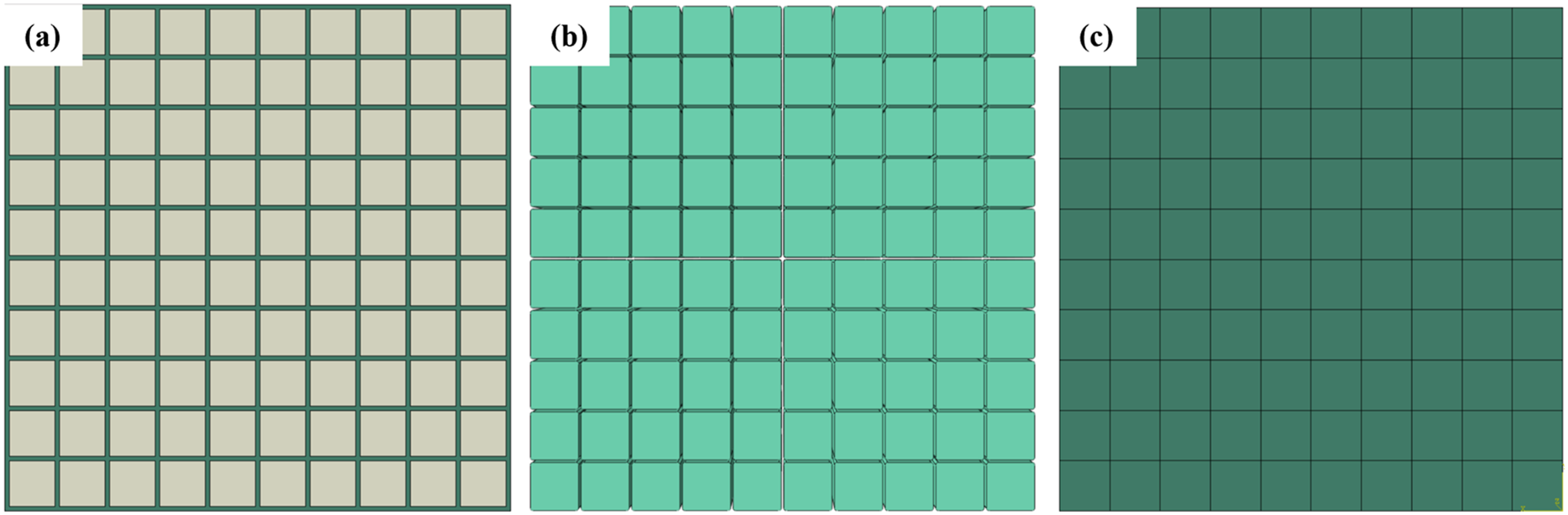
In the fully filled configuration, shared nodes enforce displacement compatibility between the fiber and matrix phases. This treatment is computationally robust and suitable for extracting effective elastic constants, but it neglects local interfacial slip, imperfect bonding, debonding initiation, and frictional contact. Consequently, the local stress-transfer path is more constrained than that in a real printed CCF/PLA tow, which may further contribute to the conservative stiffness tendency, especially in transverse deformation modes. Because the objective of this section is to construct a reduced-order RVE for macroscopic effective-constant extraction, rather than to simulate interfacial failure or microscale damage initiation, no dedicated interfacial constitutive law was introduced for the fully filled case. 32 The influence of this idealization is therefore evaluated indirectly through the comparison among geometric configurations and through the subsequent comparison with the Tandon–Weng model and Hashin–Shtrikman bounds.
For the fully filled configuration, fiber volume fraction Vf was controlled by adjusting the filament pitch p. Because s denotes the side length of the equal-area square surrogate, the fiber volume fraction satisfies Vf = (s/p)2. Three representative levels were evaluated (35%, 65%, and 95%), covering resin-rich to near-close-packed regimes (Figure 2). This design also provides an indirect assessment of fiber-spacing and interaction effects: as Vf increases, the matrix ligament between adjacent equivalent filaments becomes thinner, and the influence of the imposed square packing and shared-node constraint becomes more pronounced. Therefore, the Vf -dependent results are used not only to obtain engineering constants, but also to examine the applicability boundary of the simplified geometry under dense packing. Relationship between fiber volume fraction and filament pitch in the fully filled configuration.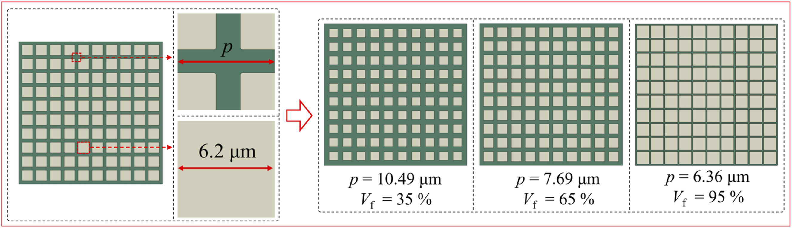
The circular-to-square mapping necessarily induces local stress concentration at inclusion corners. This local field distortion can affect damage-initiation fidelity in the matrix and may exaggerate stress gradients near the fiber-matrix boundary. However, the present work targets effective elastic constants of the RVE. Under homogenization theory, effective stiffness is a volume-averaged quantity and is therefore less sensitive to localized stress singularities than local failure prediction. This consideration supports the use of the circular-to-square simplification for macroscopic stiffness prediction while enabling substantial computational savings. At the same time, the resulting transverse and shear responses should be interpreted with this geometric limitation in mind, especially when the model is applied to failure-sensitive or interface-dominated problems.
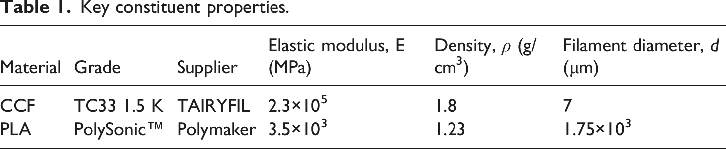
Constituent material properties
Key constituent properties.
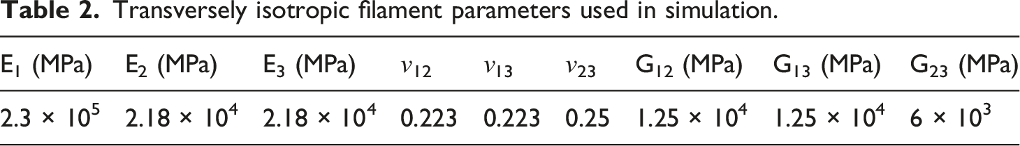
Transversely isotropic filament parameters used in simulation.
The above material treatment should be interpreted as an effective small-strain elastic approximation rather than a complete constitutive description of printed PLA. In practice, PLA may exhibit viscoelasticity, rate sensitivity, and temperature-dependent relaxation, especially during deposition or long-term loading. However, the present RVE analysis focuses on quasi-static extraction of effective elastic constants under infinitesimal deformation, where the objective is to quantify the stiffness contribution of the equivalent fiber arrangement rather than to reproduce time-dependent matrix relaxation. Therefore, the linear-elastic assumption provides a controlled baseline for comparing different Vf levels and geometric configurations. At the same time, neglecting viscoelastic compliance may make the matrix phase slightly stiffer than the real printed material, which can contribute to a conservative stiffness tendency in transverse and some shear-related responses.
Boundary conditions and extraction of effective constants
Node-to-node PBCs were applied to all RVEs, and effective engineering constants were obtained using a reaction force–displacement method. The EasyPBC plugin was used to generate node pairing and constraint equations, thereby reducing uncertainty associated with manual pairing on complex boundaries. The cuboid nominal dimensions Lx, Ly, and Lz were defined by the coordinate extrema of mesh nodes in each direction (Figure 3). Nodes on the six opposing faces were identified by EasyPBC and paired one-to-one based on non-normal coordinate differences. A tolerance of 1×10⁻⁵ mm was used to ensure unique pairing and geometric consistency. Furthermore, the regular rectangular geometry provided robust pairing behavior and mitigated failure modes common in irregular meshes (e.g., one-to-many pairing), while preventing spurious rigid-body motion or artificial constraints under periodicity enforcement. RVE geometry definition and node-pairing strategy for PBCs: (a) nominal dimensions (Lx, Ly, Lz) defined by coordinate extrema; (b) opposing-face node pairing based on coordinate tolerances.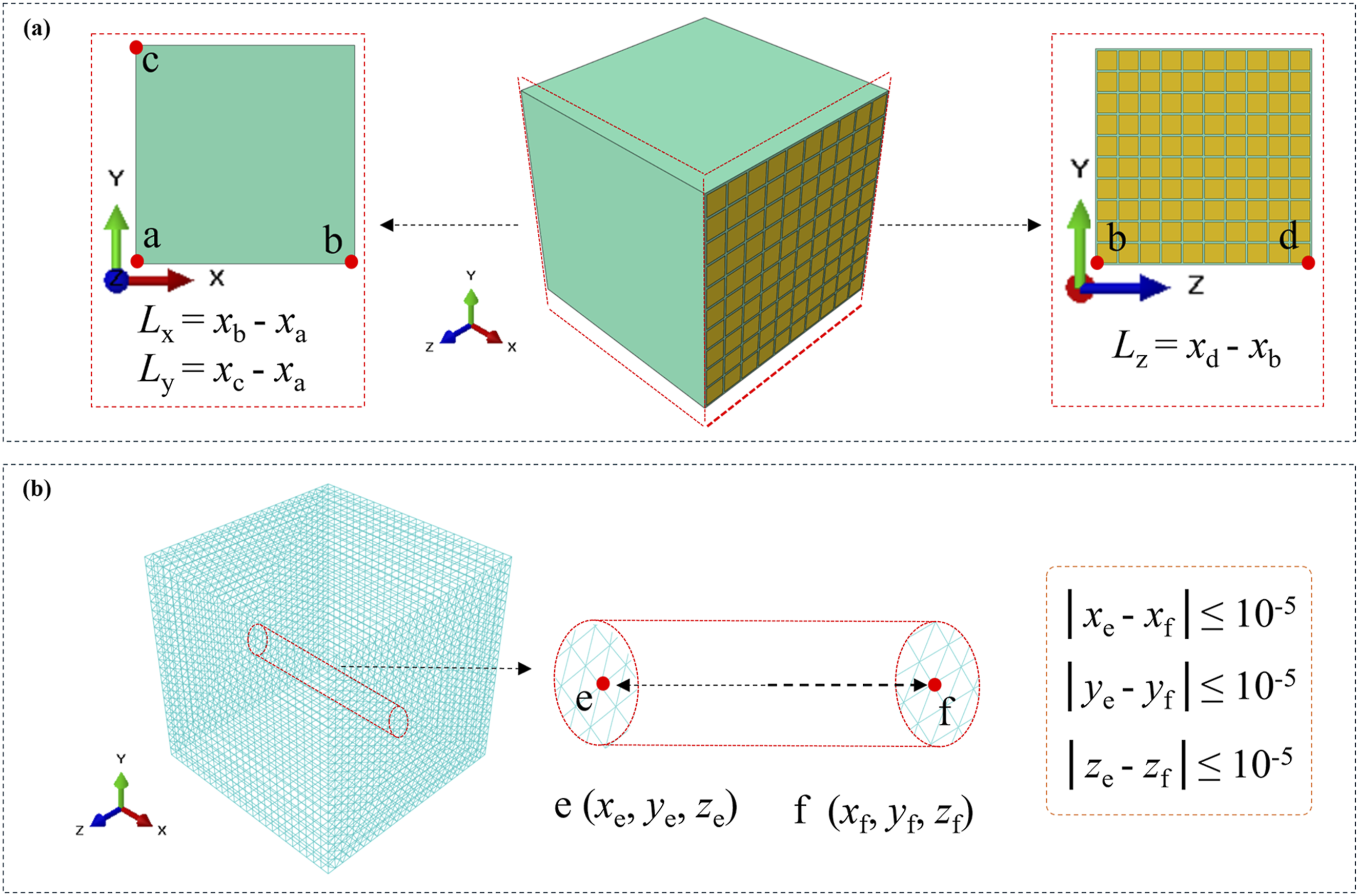
After PBCs were imposed (Figure 4), six external reference points (RP1–RP6) were introduced and coupled to the nodes of the corresponding loading faces via multi-point constraints. Independent base-displacement load cases were applied to these reference points to realize three uniaxial tension states (x, y, z) and three shear states (xy, xz, yz). Reaction forces were extracted and, via Hooke’s law, were used to back-calculate the effective stiffness matrix and engineering constants of the RVE. Reference-point-driven loading cases for extracting effective constants: (a) E1, (b) E2, (c) E3, (d) G12, (e) G13, (f) G23.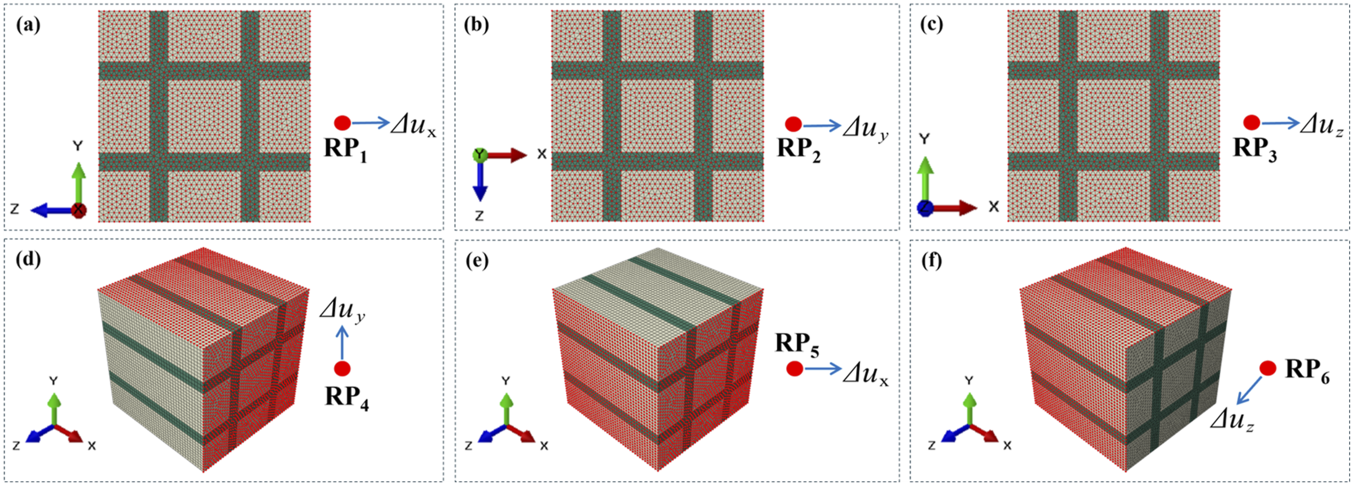
Together with the shared-node interface, the PBC formulation defines a fully bonded and periodically repeated equivalent microstructure. This treatment is required for stable homogenization and reproducible extraction of effective constants, but it also suppresses local interfacial slip, partial debonding, and microscale mismatch between adjacent filaments and matrix ligaments. Its influence is expected to be limited for E1, which is dominated by the continuous carbon fibers, whereas transverse and shear-related constants are more sensitive to this idealized constraint. The resulting stiffness tendency is therefore interpreted together with the theoretical comparison presented in the section on theoretical analysis.
Meshing strategy
Mesh design was treated as a primary factor controlling both numerical stability and accuracy, particularly at Vf = 95%, where inter-fiber gaps become far smaller than typical element sizes. To maintain consistency and reproducibility across the full parameter space, the entire RVE was discretized using C3D6 (6-node linear wedge elements) with a global mesh size of 0.003 mm. Although C3D8R or C3D10 elements are often preferred to mitigate shear locking, C3D6 offers a decisive advantage under the present rectangular-array topology: the wedge geometry naturally accommodates the diagonal partitioning implied by the square packing and can generate topologically continuous, face-to-face node-corresponding meshes even in extremely narrow gaps, which is critical for successful PBC enforcement.
While C3D6 can exhibit shear-locking tendencies, the extraction of E1 is dominated by normal stress under axial tensile loading; consequently, the influence of shear locking is comparatively limited for the axial modulus under PBCs and a near-pure normal-stress state. However, this numerical effect should not be completely neglected for transverse and shear loading cases. In particular, when the matrix ligament becomes narrow at high Vf, the combination of C3D6 discretization, regular square packing, and fully bonded displacement compatibility may restrict local deformation and thereby elevate the predicted transverse stiffness, with a component-dependent influence on the shear response. Therefore, the selected meshing strategy is treated as part of the same engineering compromise as the geometric simplification: it ensures convergence and PBC compatibility across the full Vf range, while the resulting transverse properties, together with some shear-related components, should be interpreted as conservative stiffness estimates rather than exact local-field predictions.
Theoretical prediction and error assessment
To quantify the systematic bias introduced by geometric, material, interface, and mesh simplifications, finite-element predictions were benchmarked against classical micromechanics. The Tandon–Weng model, based on Mori–Tanaka mean-field theory, was selected as the primary reference; it assumes non-interacting ellipsoidal inclusions randomly distributed in the matrix and is widely used to provide reasonable modulus estimates, sometimes tending toward a lower-bound trend. Relative error was evaluated by comparing FEM-predicted constants XFEM against theoretical values XTW. Given the square inclusion geometry, shared-node perfect bonding, linear-elastic PLA matrix, regular periodic packing, and C3D6 mesh topology, the transverse predictions, and in some cases shear-related predictions, may tend toward a stiffer response than those based on random or circular-inclusion assumptions.
Physical admissibility was further assessed using the Hashin–Shtrikman (HS) bounds, which provide theoretical limits for effective properties of two-phase composites. Predictions falling within the HS lower and upper bounds, or marginally approaching the upper-bound neighborhood when anisotropic packing and ordered microstructural constraints are considered, were treated as consistent with admissible effective behavior. In this framework, the finite-element RVE is not regarded as a fully resolved reconstruction of all local physical mechanisms, but as an idealized equivalent system for efficient stiffness extraction. The combination of transversely isotropic fibers, linear-elastic PLA, perfect bonding, and PBC-imposed periodicity is expected to preserve the dominant axial load-bearing response, while shifting the transverse response, and some shear-related responses, toward a stiffer estimation range. This treatment further defines the applicable range of the “100-to-1” downscaling strategy by relating the finite-element results to theoretical references and physical bounds, while making clear that the improved computational efficiency is achieved at the cost of certain idealized assumptions.
Simulation results
Section 3 evaluates the numerical consistency of the proposed microscale equivalent framework for CCF/PLA by (i) screening RVE geometric configurations for stable linear-elastic behavior, (ii) confirming deformation compatibility under Periodic Boundary Conditions (PBCs) and solver robustness across six independent loading cases, (iii) assessing element-type feasibility and mesh convergence at high fiber volume fraction, and (iv) extracting effective engineering constants and benchmarking them against the Tandon–Weng model and Hashin–Shtrikman bounds to quantify the systematic influence of geometric and meshing simplifications.
Validation of PBCs and solver stability
Under a consistent primary loading path (Figure 5), the fully filled configuration exhibited a smooth, strictly linear reaction force-displacement response over the entire loading range, with no nonphysical artifacts observed. The gapped configuration transferred transverse load less efficiently, producing a more compliant response with a reduced linear regime. The gap-free configuration displayed an anomalously high initial stiffness and localized deformation discontinuities because the inter-filament gaps were removed without explicitly resolving interfacial failure or contact behavior. These comparisons identify the fully filled configuration as the most mechanically consistent RVE for homogenization-based property extraction. Reaction force–displacement responses for three geometric configurations under a representative tensile case: (a) fully filled configuration; (b) gapped configuration; (c) gap-free configuration.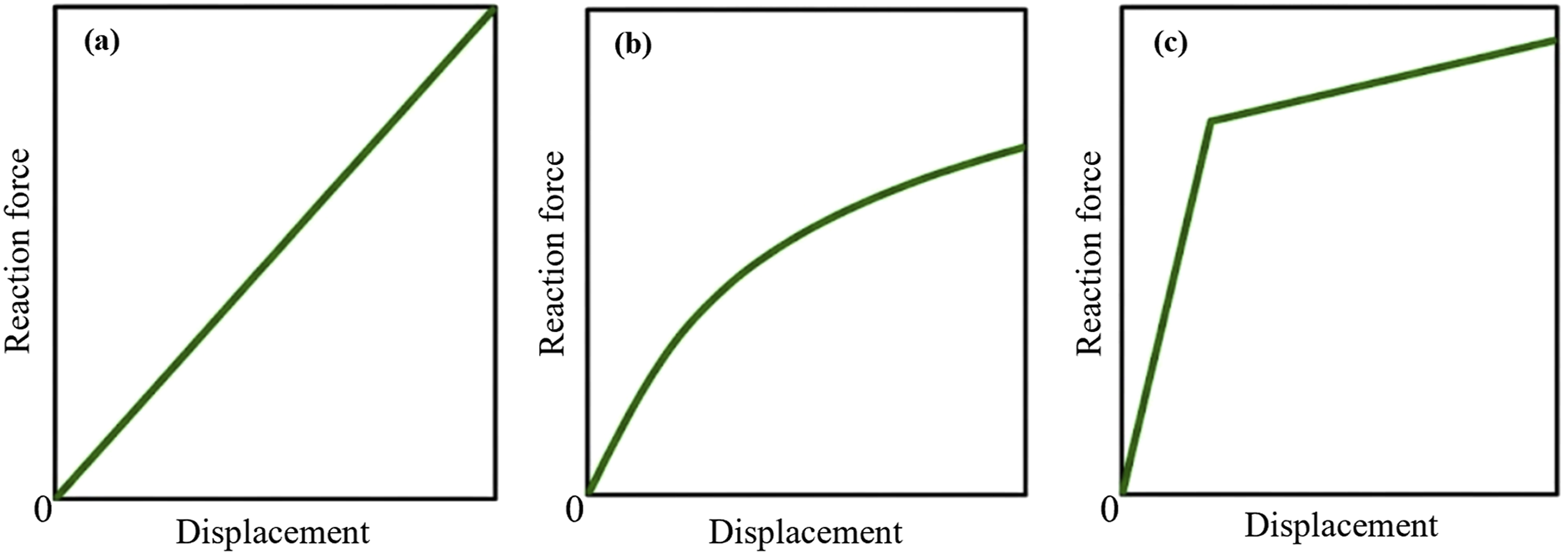
Deformation compatibility under PBCs was confirmed for the fully filled RVE. Axial displacement followed a strictly linear gradient in the loading direction, transverse displacement showed a regular layered pattern, and strain transitioned smoothly between the fiber and matrix. Stress remained concentrated in the fiber phase while transmitting continuously through the matrix, with no spurious jumps or numerical oscillations indicative of incorrect node pairing (Figure 6). Field distributions for the fully filled RVE under PBCs in x-direction tension: (a) U1; (b) U2; (c) Emid; (d) Smid.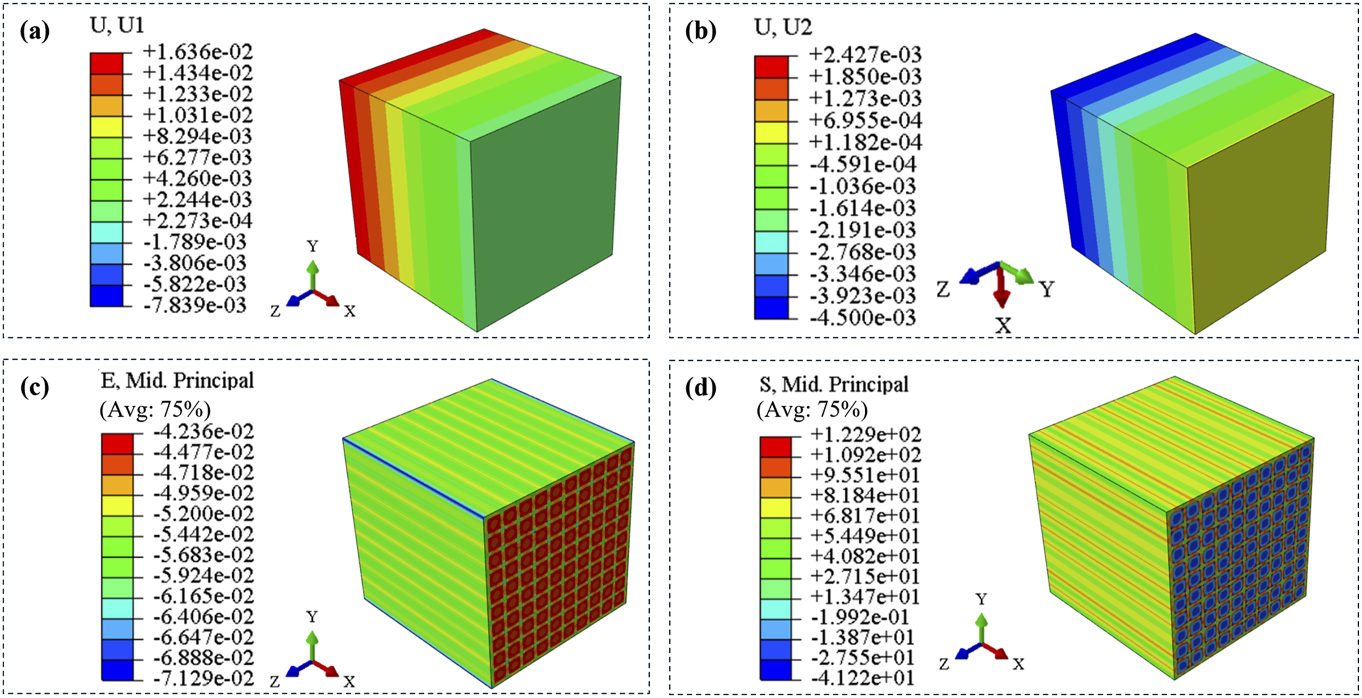
Across the six independent loading cases (Figure 7), reaction force-displacement curves remained highly linear and converged in a few solver iterations, with no stiffness-matrix singularities or unintended activation of contact-driven nonlinearity. This behavior supports the use of the fully filled RVE with PBCs for stable homogenization. Reaction force-displacement responses for the fully filled RVE under six independent loading cases: (a) E1, (b) E2, (c) E3, (d) G12, (e) G13, (f) G23.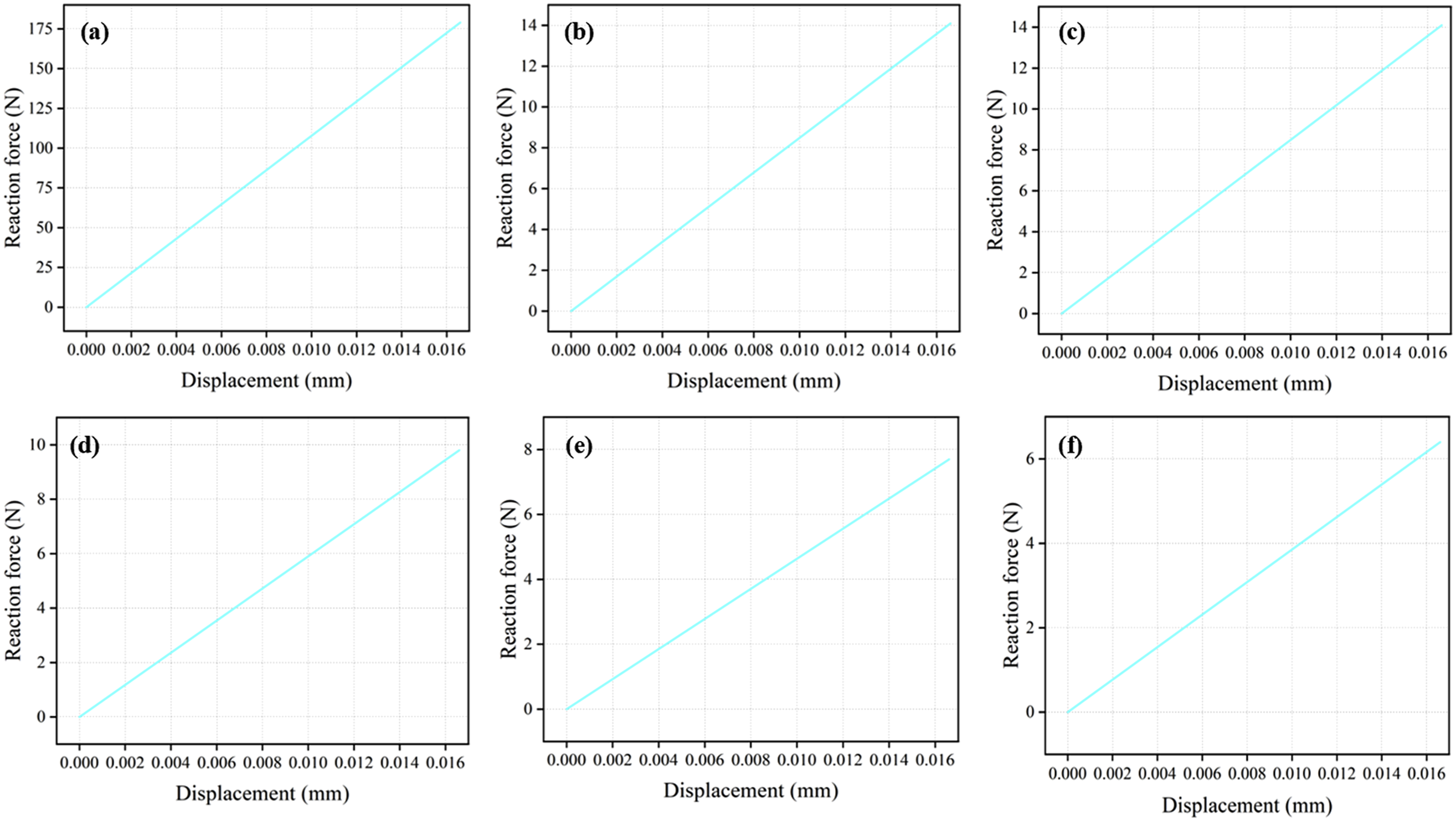
Mesh convergence and element sensitivity
Mesh generation feasibility depended strongly on fiber volume fraction (Vf) in the square-surrogate and square-packing topology (Figure 8). At Vf = 35%, C3D8R, C3D10, and C3D6 all produced valid meshes. At Vf = 65%, C3D8R suffered severe element distortion and node-matching failure within narrow matrix channels, while C3D10 frequently triggered node-pairing “Mismatch” errors on periodic opposing faces. At Vf = 95%, the theoretical inter-fiber gap became far smaller than conventional element sizes; only C3D6, leveraging its wedge geometry, generated a topologically continuous mesh with strictly corresponding nodes along the diagonal regions of the square packing. Mesh feasibility of C3D8R, C3D10, and C3D6 across fiber volume fractions: (a–c) Vf = 35%; (d–f) Vf = 65%; (g–i) Vf = 95%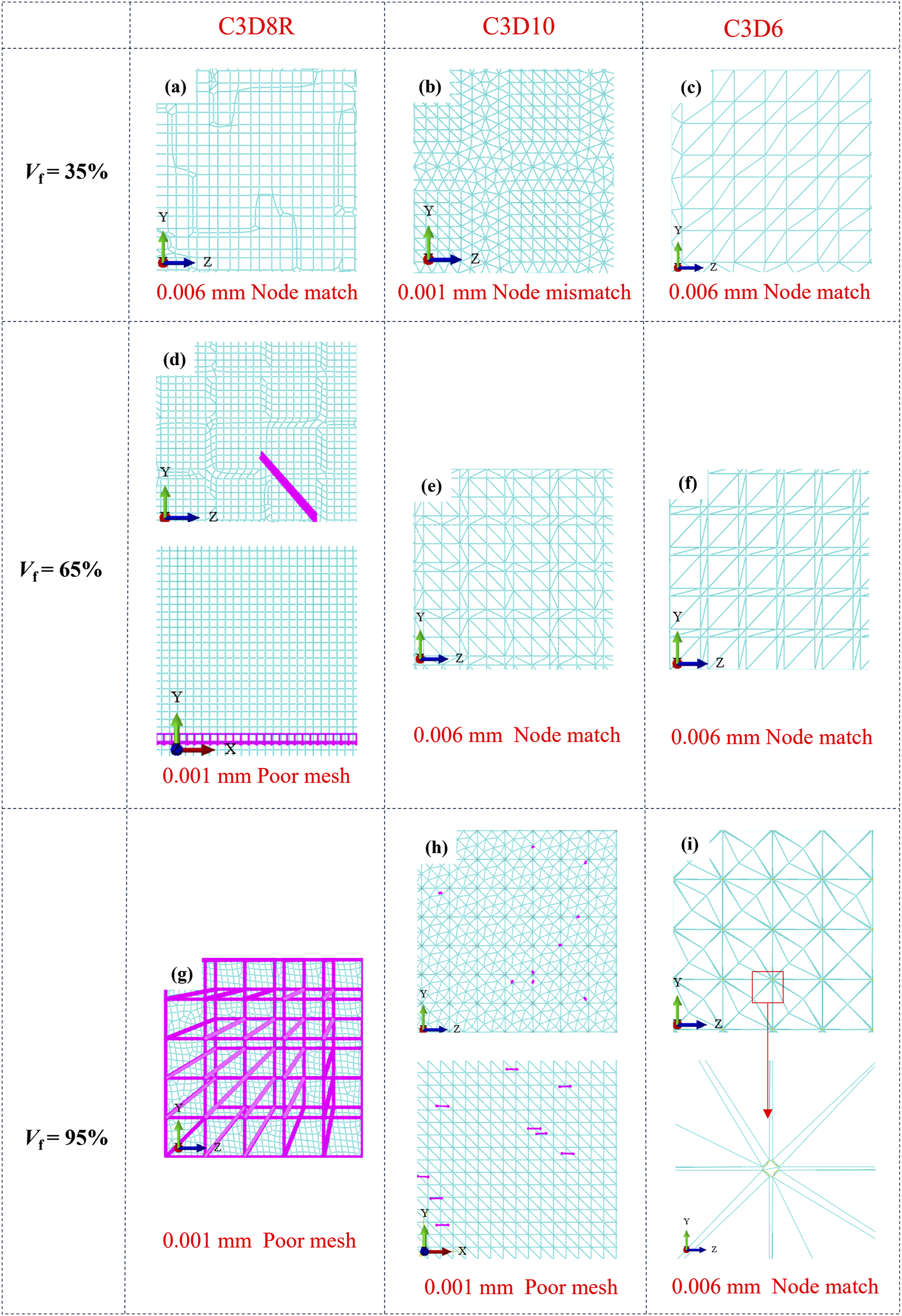
These observations explain the use of C3D6 as the uniform meshing strategy introduced in Section 2.4. This choice represents an explicit engineering compromise: linear wedge elements can exhibit shear-locking-related stiffness elevation, but they provide the most stable node correspondence and PBC compatibility under dense square packing. In the present context, that risk is accepted to secure numerical convergence for the “100-to-1” downscaling strategy under dense packing. Mesh-size convergence further supported this selection (Figure 9): once the global mesh size reached 0.003 mm, the extracted engineering constants stabilized, and further refinement produced changes within an engineering-acceptable range. Normalized convergence of effective stiffness for three fiber volume fractions using C3D6 at different global mesh sizes.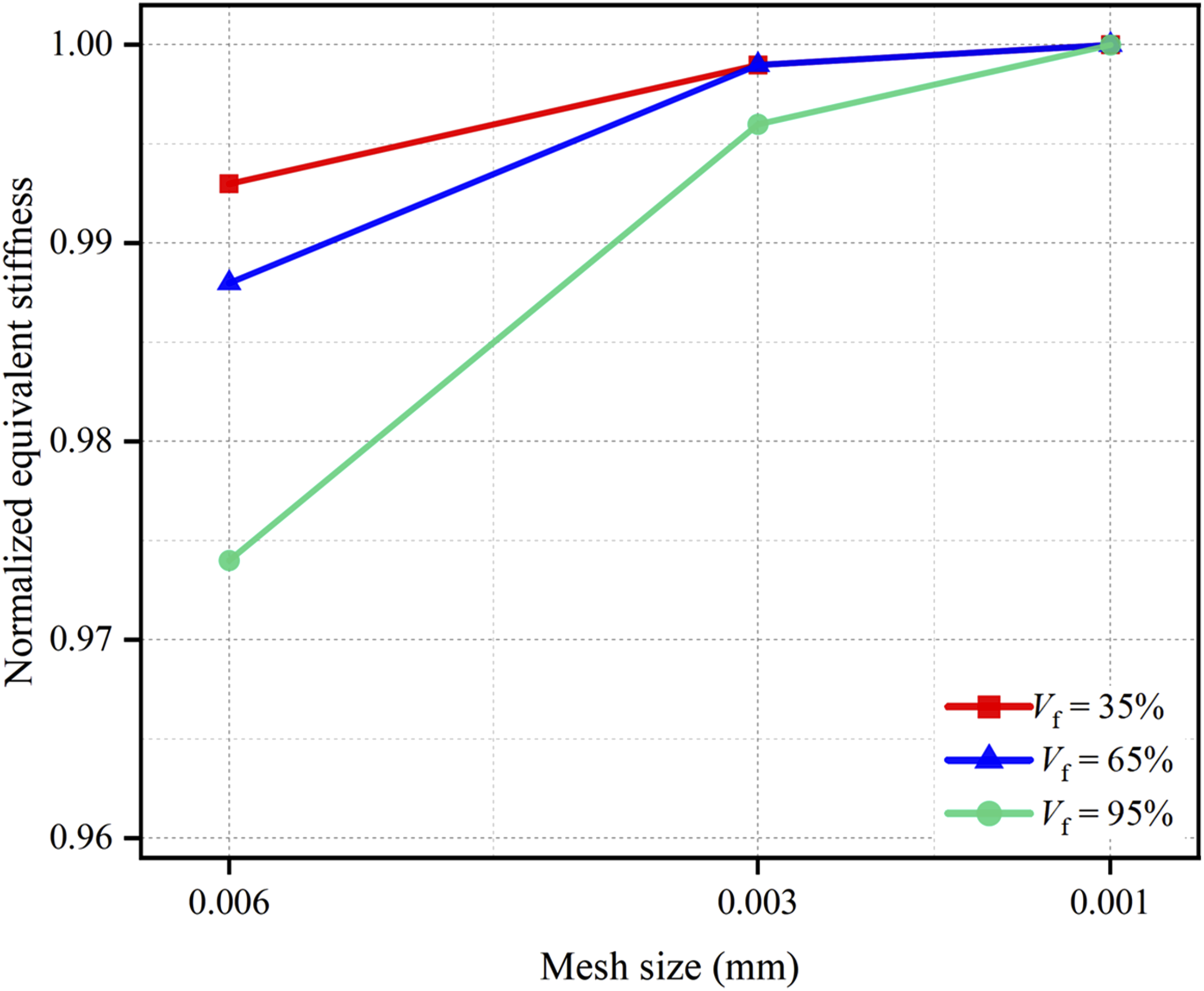
Extracted effective constants and hierarchical model comparison
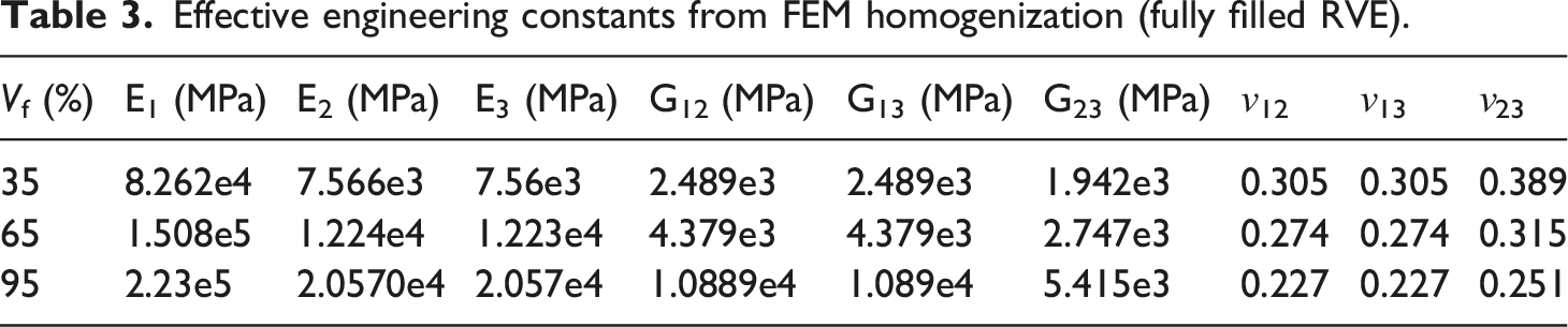
Effective engineering constants from FEM homogenization (fully filled RVE).
Tandon–Weng predictions for effective engineering constants.
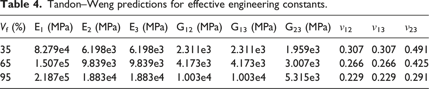
Figure 10 compares selected FEM-homogenized engineering constants with Tandon–Weng predictions across Vf = 35%–95%. E1 exhibits close agreement with the theoretical prediction, with deviations remaining within approximately 2%, confirming that the axial response is mainly controlled by the continuous carbon fibers and is only weakly affected by the cross-sectional idealization. By contrast, the transverse moduli show a more evident discrepancy. At Vf = 35%, E2 increases from 6198 MPa in the Tandon–Weng prediction to 7566 MPa in the FEM result, corresponding to a deviation of approximately +22.1%; E3 shows a similar deviation of approximately +22.0%. This deviation is mainly related to the different microstructural assumptions of the two methods. The Tandon–Weng model treats fibers as non-interacting ellipsoidal inclusions embedded in a matrix and therefore allows a more relaxed transverse deformation mode. Under PBCs and shared-node compatibility, the matrix ligaments between adjacent equivalent filaments are more strongly constrained, and the corners of the square inclusions further intensify local stress concentration. As a result, the transverse load-transfer path becomes stiffer than that predicted by the mean-field model. Comparison of effective elastic properties from FEM homogenization and the Tandon–Weng model across fiber volume fractions: (a) E1; (b) E2; (c) G12.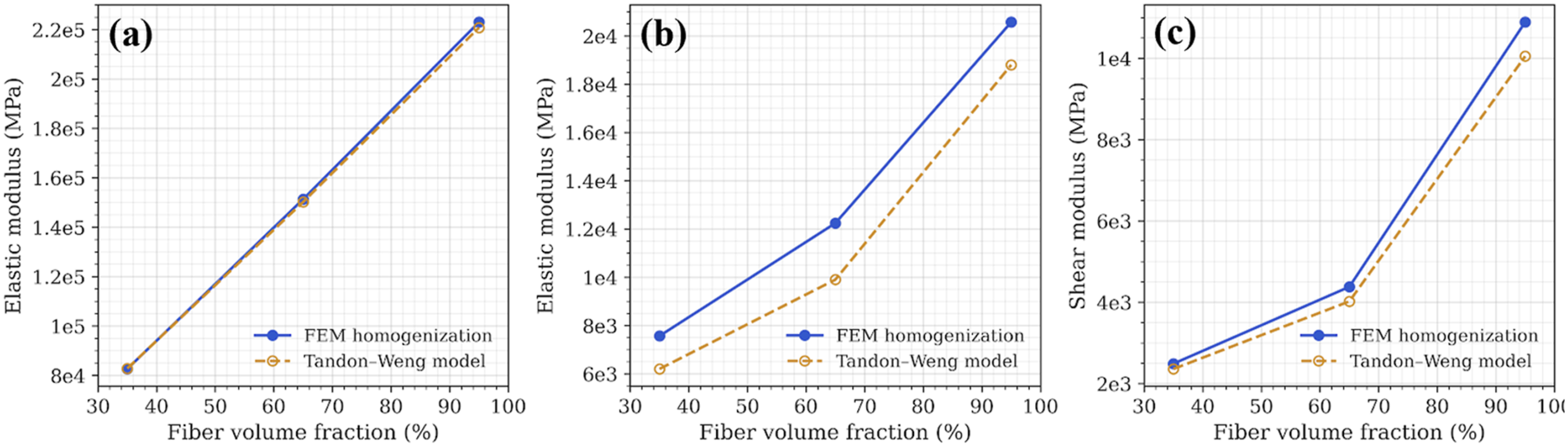
The deviation in ν23, as listed in Tables 3 and 4, should be interpreted together with this transverse constraint. At Vf = 35%, ν23 decreases from 0.491 in the Tandon–Weng prediction to 0.389 in the FEM result, giving a difference of approximately −20.8%. This trend is not associated with the axial load-bearing prediction, but reflects the restricted lateral deformation of the 2–3 plane in the square-packed RVE. In a matrix-rich configuration, transverse deformation and Poisson coupling are still strongly governed by the matrix phase. Once the circular fibers are represented by square inclusions and the fiber-matrix interface is tied by shared nodes, local matrix distortion and lateral contraction are suppressed compared with the random or circular-inclusion assumption in the Tandon–Weng model. Therefore, E2 and E3 tend to increase, whereas ν23 tends to decrease. This opposite deviation trend is consistent with a more constrained transverse deformation mode rather than with numerical instability. As Vf increases, the transverse response gradually becomes more fiber-dominated, and ν23 moves closer to the intrinsic transverse Poisson behavior of the carbon fiber phase; consequently, the relative discrepancy in ν23 is reduced at Vf = 95%.
The result at Vf = 95% should be regarded as a near-close-packed limiting case rather than a direct reconstruction of an experimentally typical CCF/PLA tow. At this fiber content, the PLA matrix ligament becomes extremely thin, and the assumption of a continuous linear-elastic PLA phase is physically idealized. In real FDM-printed CCF/PLA, such a dense filament arrangement may involve incomplete impregnation, local voids, resin discontinuity, or direct fiber-fiber contact. The fully filled RVE at Vf = 95% is therefore introduced mainly to examine the numerical robustness and applicability boundary of the proposed “100-to-1” downscaling strategy under extreme packing. Its matrix continuity should be understood as a theoretical upper-bound condition for stiffness extraction, not as a claim that a continuous and fully effective PLA network necessarily exists in the real material at this fiber volume fraction.
Despite this stiffness tendency, the FEM results remained within the admissible range defined by the Hashin–Shtrikman limits. The transverse moduli E2 and E3 were consistently higher than the Tandon–Weng predictions, whereas G12 and G13 showed only moderate positive deviations and G23 remained close to, or slightly below, the theoretical reference at some Vf levels. These results indicate that the proposed strategy provides highly accurate axial predictions while giving a conservative stiffness estimate mainly for transverse deformation under the chosen square inclusion geometry, ordered square packing, shared-node interface, and C3D6 meshing strategy. Therefore, the comparison defines the applicable range of the simplified RVE: it is reliable for axial-dominated effective stiffness extraction, while transverse Poisson coupling, near-close-packed matrix continuity, and component-dependent shear response should be interpreted within the stated idealized assumptions.
Numerical–experimental validation of the equivalent strategy
Although the CCF/PLA RVE has shown numerical stability and theoretical admissibility under homogenization, this evidence mainly establishes the consistency of the equivalent model at the microscale. Its engineering applicability still requires verification using printed specimens that contain unavoidable fiber-content fluctuation, nonuniform impregnation, and geometric defects. Therefore, the validation is extended from the RVE scale to a mesostructural single-track specimen, with emphasis on axial load-bearing capacity and stiffness response. Tensile tests were conducted to obtain the macroscopic force-displacement response, and the fiber volume fraction was measured by chemical dissolution to provide an experimentally based input for the single-track tensile model. The numerical and experimental results are then compared in terms of ultimate capacity and stiffness response, with particular attention to the contribution of system compliance to the residual discrepancy.
Single-track specimen fabrication and tensile testing
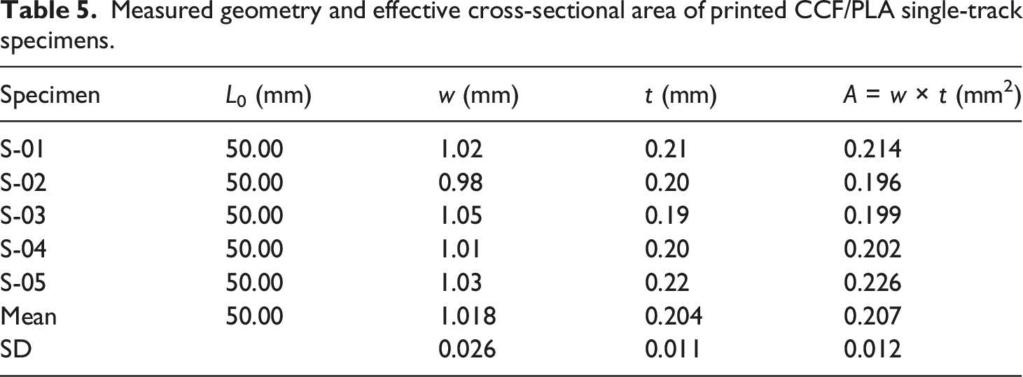
CCF/PLA single-track specimens were fabricated on a self-developed desktop 3D-printing platform using a CoreXY motion architecture and a customized brass nozzle (1.0 mm orifice) to preserve tow integrity during deposition (Figure 11(a)). Five specimens (S-01–S-05) were printed with nominal dimensions of 150 mm × 1 mm × 0.2 mm (Figure 11(b)). To reduce the influence of geometric dispersion, the stress calculation did not rely on the nominal cross-section. Instead, each specimen’s width w and thickness t were measured within the gauge section (L0 = 50 mm), and the effective load-bearing area was defined as A = w × t. Experimental equipment and specimens: (a) Printing equipment, (b) Single-track printed specimens, (c) Electric thermostatic drying oven, (d) Precision electronic balance and chemical dissolution reagent, (e) Computer-controlled electronic universal testing machine.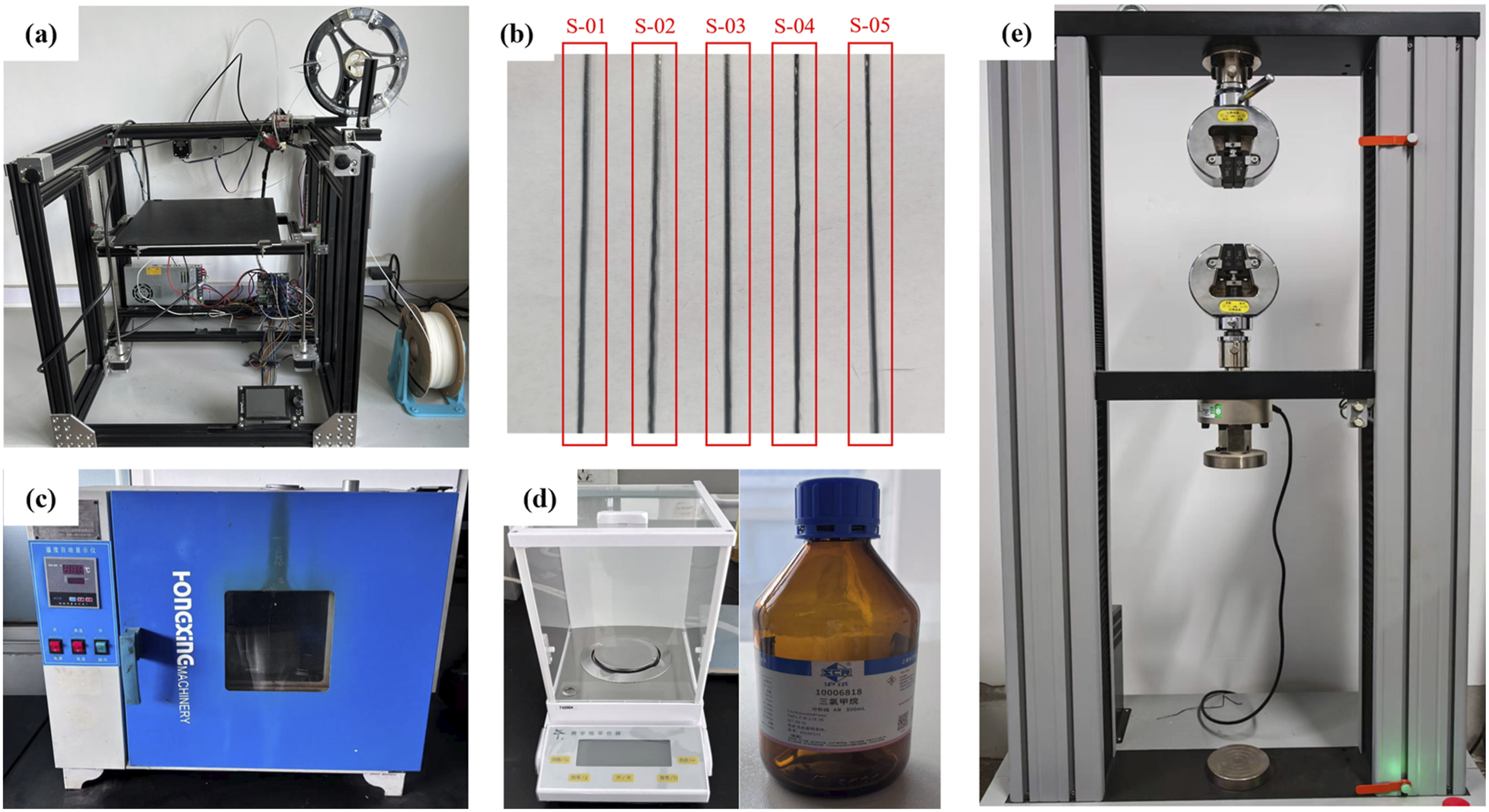
Measured geometry and effective cross-sectional area of printed CCF/PLA single-track specimens.
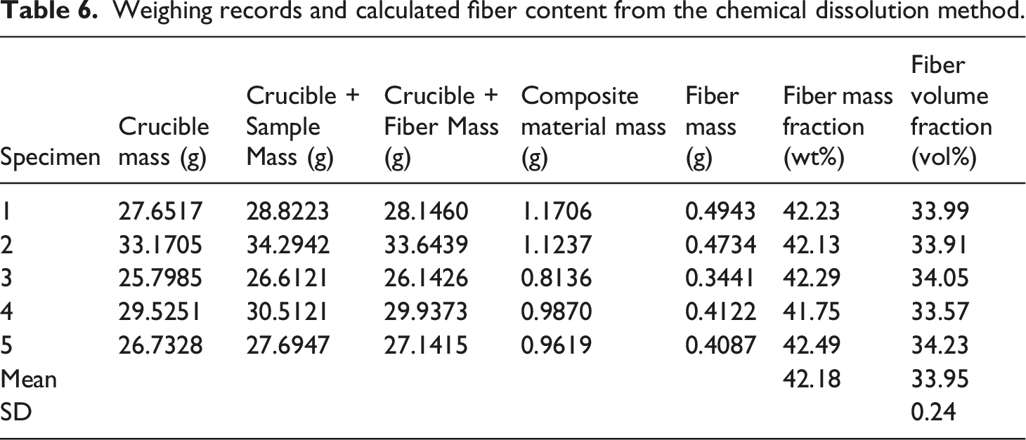
Fiber content measurement by chemical dissolution method
Weighing records and calculated fiber content from the chemical dissolution method.
Single-track tensile FE model and simulation settings
A single-track tensile FE model was built in ABAQUS/Explicit to provide a controlled axial-response comparison with the experiments. The specimen geometry was constructed using the mean dimensions from Table 5. The matrix was discretized with solid elements, while the fiber tow was simplified using the “100-to-1” downscaling strategy as an array of embedded truss elements. The model fiber volume fraction was set to approximately 32%, which is close to the measured Vf = 33.95% within the geometric discretization of the embedded-truss representation. Thus, the simulation input preserves the experimentally measured fiber-content level without relying on the nominal feedstock composition. The physical assumptions were intentionally idealized to isolate the intrinsic material response: a perfect interface (fully compatible fiber–matrix displacement) and ideal clamping (pure axial displacement at the loading end, excluding any external system compliance).
For constitutive behavior, the matrix employed an elastoplastic damage-evolution fracture criterion with element deletion at high strain, whereas the fiber phase used a maximum-stress failure criterion. The explicit dynamic setting targets brittle fracture and post-peak energy release, while quasi-static loading was verified by monitoring kinetic and internal energies (ALLKE and ALLIE) and maintaining a very low kinetic-to-internal energy ratio to suppress inertial influence on the peak prediction (Figure 12). Energy history curves (ALLKE and ALLIE) used to confirm quasi-static conditions.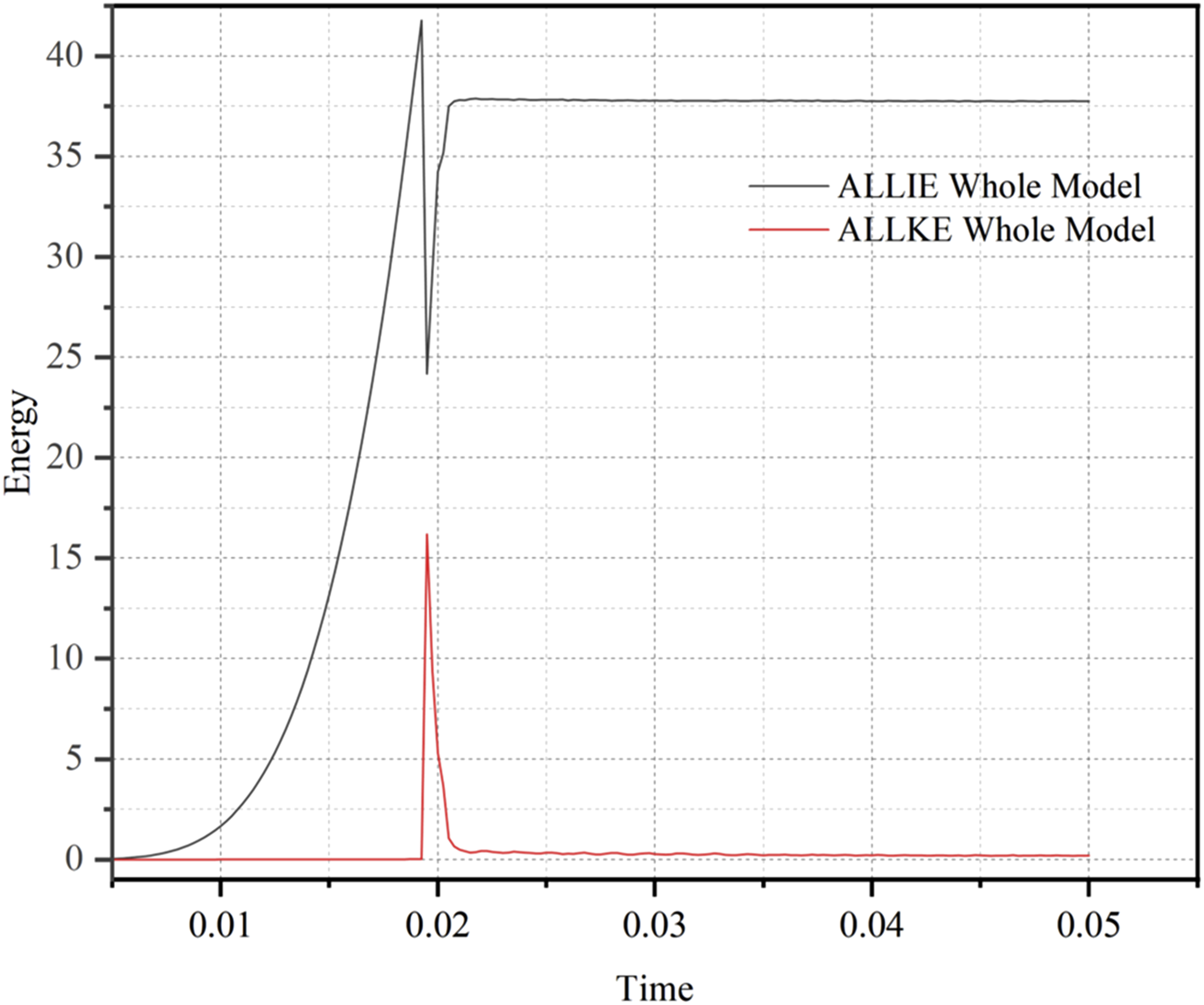
Experimental–simulation force-displacement comparison and discussion
Force-displacement curves from experiments (S-01–S-05) and the FE simulation (S-06) were plotted together in Figure 13 and evaluated in terms of initial stiffness, peak load, and failure mode. The simulation reproduces the characteristic progression of a linear rise, peak load, and abrupt load drop associated with brittle failure. Comparison of tensile force–displacement curves for experiments (S-01–S-05) and the FE simulation (S-06).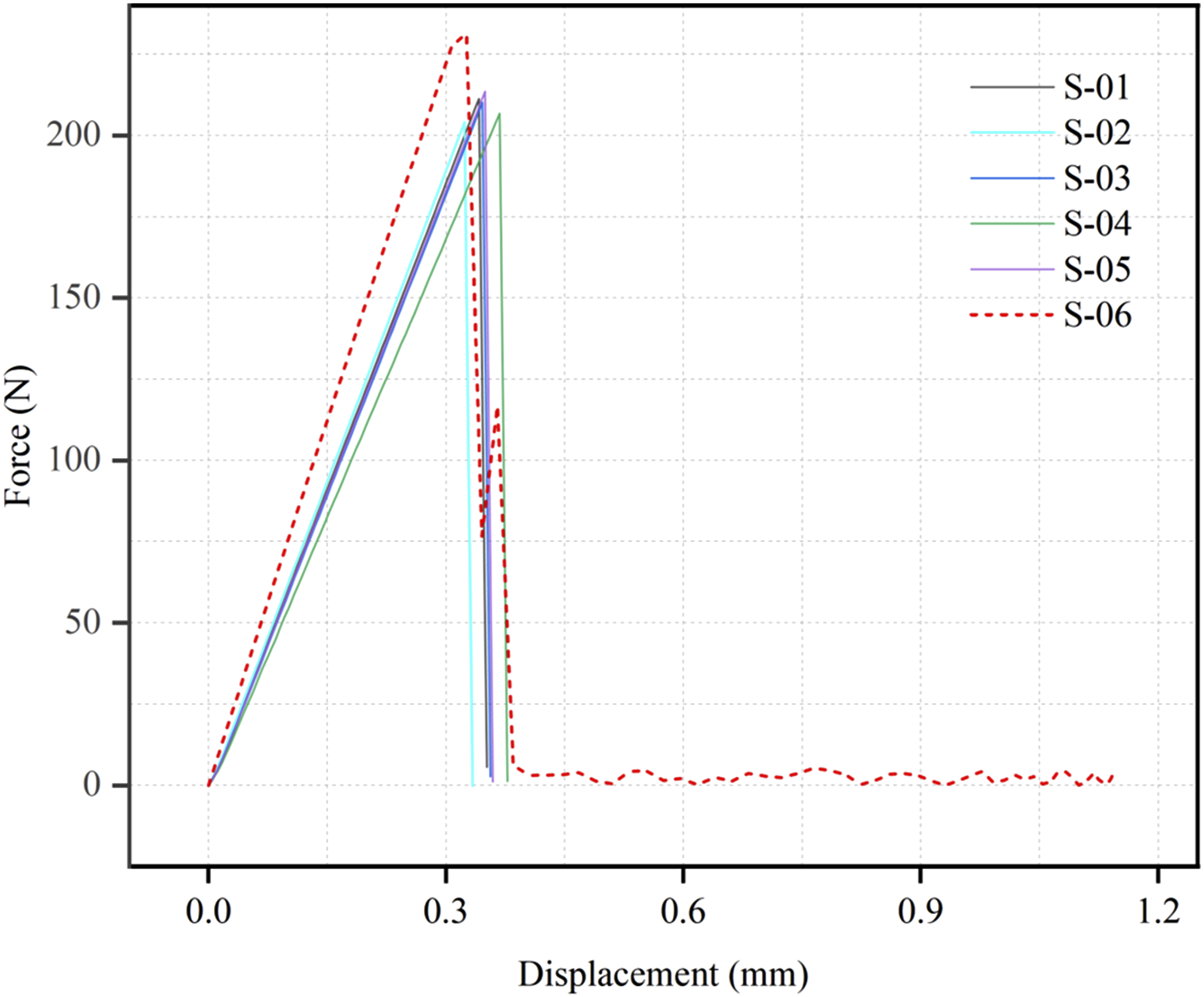
Summary of experimental–simulation comparison metrics for single-track tensile response.
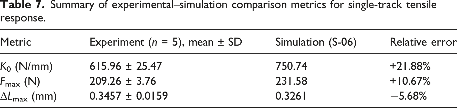
The initial stiffness shows a larger discrepancy: the simulated stiffness K0 = 750.74 N/mm exceeds the measured apparent stiffness Ktotal = 615.96 N/mm by 21.88%. Because experimental displacement was measured by crosshead motion, Ktotal includes both specimen deformation and deformation of the testing system, including the frame, load cell, grips, and drive train. To quantify this contribution, a series spring model was introduced to correct the experimental stiffness. Based on the configuration of the CMT4204 system, the effective machine stiffness was approximated as Kmachine = 10 kN/mm, corresponding to a machine compliance of Cmachine = 1/Kmachine. With springs in series, the total compliance satisfies Ctotal = Csample + Cmachine, which is equivalently expressed in stiffness form as Ksample = (Ktotal × Kmachine)/(Kmachine − Ktotal). Substituting Ktotal = 615.96 N/mm and Kmachine = 10 kN/mm yields a corrected specimen stiffness of Ksample ≈ 656.4 N/mm. This correction partly reduces the apparent stiffness discrepancy and supports a consistent interpretation: the FE prediction approaches an idealized upper estimate of intrinsic axial stiffness under perfect gripping and zero external compliance, whereas the uncorrected experimental stiffness represents an apparent lower estimate measured through a compliant test system.
It should also be noted that the corrected stiffness remains lower than the simulated stiffness of 750.74 N/mm, with a residual difference of approximately 14.37% when normalized by the corrected experimental stiffness. This remaining gap cannot be attributed to system compliance alone. Instead, it is more reasonably associated with the idealized assumptions used in the single-track FE model. First, the embedded-truss representation preserves the axial load-carrying role of the fiber tow, but it does not explicitly reconstruct real filament packing, fiber waviness, resin-rich zones, or microscopic voids in the printed track. Second, the interface between the embedded fiber phase and the matrix is treated as fully compatible, whereas the real printed CCF/PLA specimen may contain incomplete impregnation, local debonding, and nonuniform stress transfer. Third, the boundary condition in the simulation corresponds to ideal axial clamping, while the experiment may still involve residual grip compliance, slight misalignment, and local stress redistribution near the clamped region. Therefore, after system-compliance correction, the remaining stiffness difference should be interpreted as the combined effect of idealized geometry, neglected porosity, simplified interface behavior, and simplified boundary conditions.
The present single-track validation mainly evaluates the axial-dominated response of the “100-to-1” downscaling strategy. Since the experimental displacement was obtained from crosshead motion and no transverse strain measurement or digital image correlation was used, ν23 and lateral contraction of the single-track specimens were not directly extracted from the tensile tests. Accordingly, the single-track comparison should not be overinterpreted as a direct validation of transverse Poisson behavior. The discussion of ν23 and lateral deformation is instead supported by the RVE-level homogenization results in Section 3.3, where the square-packed equivalent geometry was shown to restrict deformation in the 2–3 plane and to produce a conservative transverse response. Thus, the tensile experiment confirms that the equivalent strategy can capture the dominant axial load-bearing capacity and brittle failure signature. By contrast, transverse deformation, ν23, and local lateral constraint cannot be directly validated by the present single-track tensile test and should still be interpreted based on the RVE-level assumptions regarding packing, interface compatibility, and boundary constraints. To assess failure-mechanism consistency and local stress transfer, field variables around the peak load were examined (Figure 14). Field variables and fracture evolution near peak load: (a) LE11 before peak; (b) von Mises stress before peak; (c) STATUS (element deletion indicator).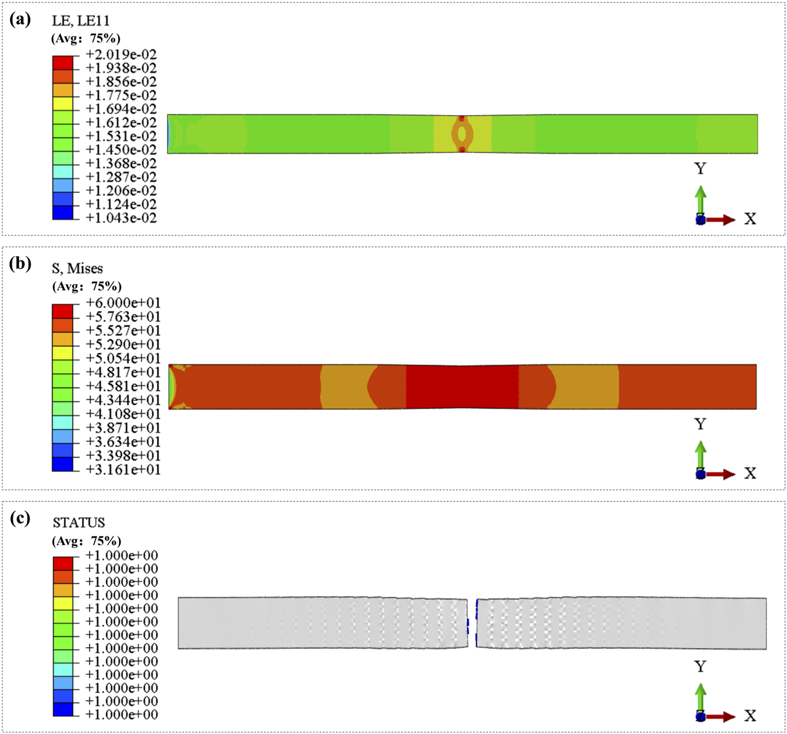
The LE11 field shows that axial strain localizes within the gauge section rather than at the clamped ends, indicating that the idealized boundary condition does not artificially trigger premature end failure. The von Mises stress field further shows that stress concentration develops along the embedded fiber path and adjacent matrix region before element deletion occurs. This stress pattern is consistent with axial load being primarily carried by the continuous fiber phase, while the surrounding PLA matrix provides lateral constraint and transfers stress between the embedded reinforcement and the external specimen boundary. However, because the fiber tow is represented by embedded truss elements rather than explicitly resolved circular filaments, the model cannot describe the detailed stress distribution around each individual fiber or the local debonding process at a real fiber-matrix interface. Therefore, Figure 14 supports the consistency of the macroscopic failure location and axial stress-transfer path, but it also reflects the limitation of the simplified packing representation for local transverse and interface-dominated stress fields.
Overall, the experimental loop supports the single-track extension of the microscale framework within its intended axial-dominated validation scope. The measured Vf ≈ 34% provides physically grounded simulation inputs, and the ultimate-load prediction error of approximately 10% indicates that the model can reasonably capture the load-bearing capacity of the printed single-track specimen. The initial stiffness discrepancy of 21.88% is partly reduced and physically interpreted after introducing the system-compliance correction, confirming that testing-machine and grip compliance are important contributors to the apparent experimental compliance. Nevertheless, the remaining 14.37% stiffness gap indicates that the FE model still tends toward an idealized upper estimate of the axial stiffness. This residual difference is most plausibly related to the combined influence of idealized fiber geometry, neglected porosity, perfect fiber-matrix compatibility, and simplified axial boundary conditions. Thus, the validation confirms the engineering utility of the “100-to-1” strategy for axial stiffness and ultimate-load prediction, while transverse deformation, ν23, and local fiber-scale stress fields should be interpreted within the limitations of the simplified equivalent model.
Conclusions
This work addressed the cross-scale modeling bottleneck in FDM-printed CCF/PLA by proposing a microscale “100-to-1” downscaling strategy. Circular carbon filaments were represented by equal-area square surrogates, so that the fiber volume fraction was preserved while the filament-level geometric complexity was substantially reduced. Based on RVE homogenization, theoretical comparison, and single-track tensile validation, the main conclusions are as follows: (1) A reduced-order RVE framework suitable for CCF/PLA was established. The combination of a regular 10×10 filament array, equal-area square-surrogate mapping, node-to-node PBCs, and C3D6 meshing provided stable extraction of effective engineering constants over Vf = 35%–95%. This framework effectively avoided the meshing difficulty commonly encountered in filament-resolved tow models, especially under dense packing. Therefore, the proposed strategy provides a reproducible numerical basis for subsequent path- and component-scale simulations where explicit modeling of all micron-scale filaments would be computationally impractical. (2) The equivalent RVE retained the dominant axial load-bearing response, while the transverse response showed a conservative stiffness tendency and the shear response remained component-dependent. The axial modulus agreed well with the Tandon–Weng prediction, with deviations remaining within approximately 2%, indicating that the continuous-fiber contribution along the filament direction was preserved after downscaling. By contrast, the transverse moduli E2 and E3 were higher than the Tandon–Weng results, with deviations mainly ranging from approximately 9% to 24%, whereas the shear moduli showed weaker and component-dependent deviations. This behavior is mainly associated with the equal-area square inclusion geometry, ordered square packing, shared-node fiber-matrix compatibility, and C3D6 mesh constraint, which restrict local matrix deformation and strengthen the transverse load-transfer path. Therefore, the transverse properties predicted by the present model should be interpreted as conservative stiffness estimates, while the shear response should be evaluated according to the specific shear component. The lower ν23 obtained from the FEM results, particularly at Vf = 35%, further indicates that lateral deformation in the 2–3 plane is constrained by the square-packed RVE. Nevertheless, these predictions remained within the Hashin–Shtrikman admissible range, supporting the physical consistency of the equivalent strategy under the stated assumptions. (3) The single-track tensile validation confirmed the engineering applicability of the strategy for axial-dominated response, while also revealing the remaining limitations of the simplified model. The measured Vf ≈ 34% provided physically grounded input for the tensile simulation, and the predicted ultimate load differed from the experimental mean by approximately 10%. The initial stiffness discrepancy between simulation and experiment was 21.88%, and the introduction of the system-compliance correction partly reduced this discrepancy and provided a physical interpretation for the remaining difference. However, the corrected experimental stiffness still remained lower than the FE prediction, leaving a residual gap of approximately 14.37% when normalized by the corrected experimental stiffness. This remaining difference suggests that the FE model still tends toward an idealized upper estimate of the axial stiffness, mainly due to idealized fiber geometry, neglected porosity, perfect fiber-matrix compatibility, simplified axial boundary conditions, and the square-packing representation of the tow. Accordingly, the proposed “100-to-1” strategy is suitable for efficient prediction of axial stiffness and ultimate load in CCF/PLA, whereas transverse deformation, ν23, component-dependent shear response, and local fiber-scale stress fields should be interpreted within the assumptions of the simplified equivalent model rather than as directly validated quantities.
Footnotes
Declaration of conflicting interests
The authors declared no potential conflicts of interest with respect to the research, authorship, and/or publication of this article.
Funding
The authors received no financial support for the research, authorship, and/or publication of this article.