





Abstract
In this study, a facial method of fabricating hexagonal boron nitride nanosheet (BNNS) was proposed. Isopropyl alcohol was employed as the solvent to obtain the BNNS via exfoliation of the pristine hexagonal boron nitride. The yield of the exfoliated BNNS with thickness less than 20 nm was as high as 0.17–0.2 mg mL−1. The BN- and BNNS-filled polyamide 6 (PA6) composites were subsequently prepared by melt blending, and a comparison of thermal conductivity and mechanical properties of the resultant composites were demonstrated. Results indicated that the PA6/BNNS composites showed superior mechanical and thermal conductive properties when compared with that of neat PA6 and PA6/BN composites. At a filler-loading fraction of 40 wt%, thermal conductivity of the PA6/BNNS composite reached 2.496 W mK−1, which was 21.8% higher than that of PA6/BN composites at the same filler-loading concentration. In addition, the tensile strength of PA6/BNNS composites was invariably higher than that of neat PA6, with a 6.23% increment at a filler concentration of 30 wt%. Based on the results of differential scanning calorimetry, a new crystallization peak (TCC, 2) was observed at higher temperature region for the filler-containing composites and the position of the new peak gradually shifted to higher temperatures with an incremental loading concentration of BN and BNNS.
Keywords
Introduction
Nowadays, polymeric composites have a ubiquitous application in everyday life due to their tailorable electrical, thermal, mechanical, and optical properties. Lightweight composites with highly thermal transport properties have been seen to have a great potential to apply in areas of electronics, heat sinks, and heat exchangers. 1 –6 For example, there is a miniaturization trend in electronic devices with the joint advancement of material science and engineering. However, the heat dissipation for these miniature components becomes an issue for the fact that more and more functions are combined together in a limited area. 7,8 However, the thermal conductivity of the typical polymeric material is usually in the range of 0.1–0.5 W mK−1. It becomes one of the bottleneck problems for the continuous development in electronic industries. 9 It has been reported that thermal conductivity of polymeric materials could be greatly enhanced by the introduction of highly thermal conductive fillers into the host pure plastics. 10 –13 Typical filler materials include metals, carbon-based materials (carbon fiber, graphite, diamond), and ceramics (boron nitride and alumina nitride, etc.). In order to achieve reasonable thermal conductivity of polymeric composites, high volume or weight fraction of thermal conductive fillers is necessary for conventional microsized spherical or flake fillers to ensure the construction of heat transport pathways with the host matrix. The incorporation of very high volume fraction of inorganic fillers deteriorates the processability of materials and mechanical properties of final products. Therefore, novel nanofillers with ultrahigh intrinsic thermal conductivity and a high aspect ratio which could improve thermal conductivity have attracted much attention of numerous researchers. Recently, single-layer and fewer layer graphene sheets have demonstrated their advantages over carbon nanotubes, especially when it comes to the enhancement of thermal conductivity. 14 –18 However, due to their electric conductivity, carbon-based fillers are not suitable for applications where both good thermal conductivity and electronic insulation are required. 19,20
Hexagonal boron nitride (h-BN) is one of the typical thermal conductive ceramic fillers which is structurally analogous to graphite and has comparable thermal transport properties. When compared with carbon-based fillers, BN features a constant wide band gap (5.5 eV), a small dielectric constant (3.9), higher chemical inertness and thermal stability, resistance to oxidation, and good optical properties. 21 –24 Hexagonal boron nitride nanosheet (BNNS) which is structurally identical to graphene nanosheet possesses very high thermal conductivity (1700–2000 W mK−1), 25 thus shedding light on the development of electrically insulating but thermally conducting polymeric composites. 26,27 So far, few studies have been carried out with the application of BNNS to improve the thermal conductivity of polymers due to the challenge of large-scale fabrication of the nanosheets. Liquid-phase exfoliation of BN has been demonstrated as a success to prepare exfoliated BNNSs. 28 –30 However, the drawback of this method is the low yield which is not enough for real applications. For instance, Zhi et al. 31 directly sonicated 1 g of h-BN in 40 mL N,N-dimethylformamide for 10 h, yielding only 0.5–1.0 mg of BNNS. Therefore, it is of great importance to find an efficient route to exfoliate BN on a large scale to ensure its possible application in certain areas.
In the current study, a facial method of large-scale fabrication of two-dimensional BNNS was reported. Isopropyl alcohol (IPA) was employed as the medium to exfoliate BNNS from the pristine BN particles. The resultant BNNS was utilized as a reinforcement filler to enhance the thermal conduction and mechanical properties of polyamide 6 (PA6). A comparison of thermal conduction and mechanical properties was drawn between the PA6/BN and PA6/BNNS composites. In addition, the thermal behavior of corresponding filler-loaded composites was investigated by differential scanning calorimetry (DSC).
Experimental procedure
Materials
h-BN with a particle size of 16.5 µm and density of 0.2–0.4 g cm−3 was supplied by Zibo Jonye Ceramic Technology Co., Ltd. (China). IPA was purchased from Chengdu Kelong Chemical Co., Ltd. PA6 (Ultramid® B3S), with a melt volume-flow rate of 175 cm3 10 min−1 (275°C, 5 kg) and density of 1.13 g cm−3, was purchased from BASF Corp. (Germany). The above data were provided by the manufacturers. All materials were used as received.
Sample preparation
Exfoliation of h-BN
Firstly, 1 g of the pristine h-BN was dispersed in 500 mL IPA in a three-necked bottle. Then, in order to exfoliate h-BN into BNNS, the mixture was subjected to sonication at 50°C for 6 h in a 200-W power sonic bath. Finally, the exfoliated BNNSs were collected by vacuum rotary evaporation. After deposition for 24 h, the BNNS was repeatedly washed by acetone and dried under vacuum overnight at 85°C.
Fabrication of PA6/BNNS and PA6/BN composites
Prior to blending, the PA6 pellets were dried under vacuum oven overnight at 85°C, while the as-prepared BNNS and the pristine BN particles were dried at the same condition for 6 h. A Brabender internal mixer (Duisburg, Germany), equipped with contra rotating blades, was used to prepare the thermally conducting composites. PA6 was blended with various percentages of BNNS and BN. The composition of PA6/BN and PA6/BNNS composites is tabulated in Table 4. The specimens used for thermal conductivity measurement were compression molded under the conditions of preheated for 10 min, under the pressure of 10 MPa applied for 5 min at 240°C, and then cooled instantly under pressure to room temperature.
Chemical composition of BN and BNNS.

BN: boron nitride; BNNS: boron nitride nanosheet; B: boron; N: nitrogen; C: carbon; O: oxygen.
The statistical size distribution of BN and BNNS via laser diffraction particle size analyzer.

BN: boron nitride; BNNS: boron nitride nanosheet.
The melting and crystallization data of PA6 and PA6 composites.

PA6: polyamide 6.
TEF of PA6/BN and PA6/BNNS composites with different filler fractions.

TEF: thermal enhancement factor; PA6: polyamide 6; BN: boron nitride; BNNS: boron nitride nanosheet.
Material characterization
X-ray photoelectron spectroscopy
The chemical composition of h-BN and BNNS was investigated by X-ray photoelectron spectroscopy (XPS, XSAM800 multifunctional surface analyzer instrument, Kratos, UK).
Fourier transform infrared
Infrared (IR) spectra were taken with a Fourier transform infrared (FTIR) spectrometer (Nicolet iS10, Thermo Fisher Scientific, Waltham, Massachusetts, USA). To avoid the influence of the adsorbed moisture on potassium bromide, a specially assembled accessory whose sample chamber could be purged with nitrogen gas or evacuated at elevated temperatures was built into the spectrometer. The sample was firstly heated from 30°C to 160°C at a heating rate of 5°C min−1, and then kept at 160°C for 15 min to eliminate the eventual traces of moisture.
Morphology and nanostructure characterization
The morphology of the composites and inorganic particles were observed using a scanning electron microscope (SEM, JSM-5900, JEOL, Japan) and a transmission electron microscope (TEM, Tecnai G2 F20, FEI, Hillsboro, Oregon, USA) instruments. The size distribution of inorganic particles was characterized by a laser diffraction particle size analyzer (Malvern Mastersizer 2000, Malvern Instruments Ltd, Malvern, UK). The parameters D(0.1), D(0.5), and D(0.9) were the particle sizes at which 10%, 50%, and 90% of all the particles by volume were smaller, respectively. 32 The density of BN and BNNS was carried out by a density tester (Zhongyi PT-100E, China).
Atomic force microscopy
Atomic force microscopy (AFM) images were taken on a Nanoscope Multimode and Explore AFM (Veeco Instruments, Town of Oyster Bay, New York, USA). All images were collected under ambient conditions at 50% relative humidity and 18°C with a scanning raster rate of 2 Hz. Samples for AFM images were prepared by depositing dispersions of BNNS in IPA on the surface of silicon (Si) wafers and then dried under vacuum overnight at 80°C.
Differential scanning calorimetry
The melting and crystallization behavior of the composites were determined using a differential scanning calorimeter (DSC-204, Netzsch, Germany). First, the sample was fast heated to 250°C at a rate of 40°C min−1 and held for 5 min to eliminate the thermal history. Subsequently, the sample was cooled at a rate of 10°Cmin−1 to 50°C and held for 3 min. It was then scanned from 50°C to 250°C at a heating rate of 10°C min−1. The crystallinity (χ c) of the composites was calculated with equation (1):
where ΔH m is the melting enthalpy of polymer for the composites, while ΔH calc represents the expected melting enthalpy for PA6 with χ c of 100%. The melting enthalpy of 100% crystalline polymer for PA6 is 190 J g−1. 33
Thermal conductivity measurement
The thermal conductivity measurement of the composites was carried out by a Thermal Constants Analyzer (Hot Disk TPS 2500, Sweden). The samples used in the test are 4 mm in thickness, and the hot disk sensor is a circular plate with a radius of 3.189 mm. The thermal enhancement factor (TEF) 34 is introduced as a factor to assess the enhancement of thermal conductivity of corresponding composites, which is defined as follows:
where K refers to the thermal conductivity.
Mechanical properties measurement
Mechanical properties were measured using a universal mechanical tester (Instron 5565, Instron, Norwood, Massachusetts, USA). The dumbbell-shaped specimens were prepared via injection molding (HAAKE MiniJet, Thermo Fisher Scientific). The tensile testing was carried out at a crosshead rate of 10 mm min−1 according to standard ISO 37-1994.
Dynamic rheology measurement
Viscoelastic behavior of the samples was analyzed in a dynamic rheometer (Bohlin Gemini 2000, Malvern Instruments Ltd) in the melt state. The samples were studied under a constant strain mode and the applied strain was set at 1%. All the samples were tested in a frequency sweep range from 0.01 Hz to 100 Hz. Storage modulus (G′), loss modulus (G′′), and complex viscosity (η*) of all samples were recorded as a function of angular frequency (ω).
Results and discussion
Synthesis and characterization of BNNS
Vigorous sonication was able to exfoliate BNNSs from the pristine BN particles. IPA was selected as the solvent because its surface energy matches the energy per unit area that requires to overcome the Van der Waals force between different BN layers. Thus, it was believed that the sonication was able to delaminate BNNS from the BN particles due to the strong polarity of the solvent and its interaction with BN particles.
XPS is a more sensitive tool to detect the chemical status of a material and thus it is used to investigate the chemical composition of h-BN and BNNS. From Figure 1, it can be seen that boron (B), nitrogen (N), carbon (C), and oxygen (O) were presented in both BN and BNNS. The high-resolution B1s scan of BN showed that the B1s peak was centered at 190.4 eV and the N1s peak of h-BN was located at 397.9 eV, which was consistent with the reported values in literatures. 29 The existence of elements C and O in the BN and BNNS could be attributed to the presence of B2O3 and carbon contamination, which was commonly seen in BN materials. The variation of atomic composition ratio obtained from high-resolution XPS spectra considering with atomic sensitivity factor is summarized in Table 1. It was indicated that the atomic ratio of O increased from 2.86% for BN to 4.91% for BNNS. The increase in the ratio of O atoms suggested that some oxygen-contained groups have been introduced into the BNNS during the sonication process. 35
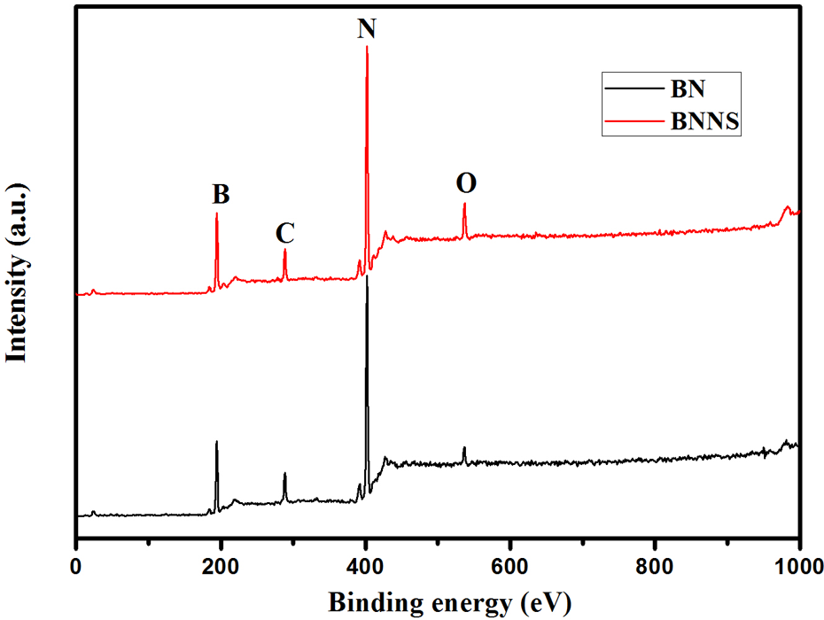
XPS spectra of BN and BNNS. XPS: X-ray photoelectron spectroscopy; BN: boron nitride; BNNS: boron nitride nanosheet.
The FTIR was carried out at room temperature (23°C) and high temperature (160°C) to investigate the surface functional groups of BN and BNNS. It can be seen from Figure 2 that both the BN and BNNS displayed two dominant peaks at 816 cm−1 and 1368 cm−1, which were attributed to the shearing of B–N–B bonds and stretching of B–N bonds. 29 Observing from the spectra obtained at room temperature, the broad absorption band centered around 3400 cm−1 was difficult to judge for both BN and BNNS fillers because of the absorbed moisture on the surface of these particles. After the sample was heated to 160°C for 15 min, the moisture was eliminated. From the inserted FIIR spectra of BNNS in Figure 2(b), three prominent absorption bands were detected at the wavenumber of 3410, 3250, and 3420 cm−1. The absorption band of 3410 cm−1 could be ascribed to the free –OH stretching vibration of the B–OH surface groups. 8 Similarly, the absorption bands centering around 3250 and 3420 cm−1 could be attributed, respectively, to the antisymmetric and symmetric NH2 stretching vibrations in the B–NH2 surface groups. 35 –37 The existence of absorption bands observed at high temperature indicated that B–OH and B–NH2 groups were stable even in such harsh conditions. These stable functional groups should contribute to the enhanced compatibility of the BNNS filler with organic solvents and plastics.

The FIIR spectra of BN (a) and BNNS (b) at various conditions. Insets show the enlarged region of 3000–3800 cm−1. FTIR: Fourier transform infrared; BN: boron nitride; BNNS: boron nitride nanosheet.
In addition, three weak absorption bands at 3410, 3380, and 3420 cm−1 were found at 160°C for BN in Figure 2(a), indicating that B–OH and B–NH2 existed on the edge planes of the BN crystals. 37 The IR spectral measurements confirmed that BN particles with typical shapes and sizes possessed fewer surface functional groups than the BNNS filler.
Morphology and nanostructure of BN and BNNS
Figure 3(a) is a photograph of dispersions of the pristine BN and BNNS stabilized in IPA after sonication at 50°C for 6 h in a 200-W power sonic bath. After 24-h deposition, it could be clearly seen that IPA-BN supernate was almost transparent. Also comparable was that the BNNS dispersion had a milky appearance, further evidenced that after long-time sonication, the thickness of BN was significantly reduced. The morphology of BNNS was characterized by microscopic studies and compared to that of the pristine h-BN. From Figure 3(b), it was clearly demonstrated that the pristine BN powder was composed of BN blocks of large size. In contrast to the BN particles, the thickness of BNNS was significantly reduced, the stacked, layered structure of BN was mostly delaminated. The representative micrograph in Figure 3(c) and (d) showed some BNNSs had curled edges, consistent with the expected nanoscale thickness. These different features can be attributed to induced scission of sonication. The sonication was able to peel off BNNS from the particles due to interactions between solvent molecules and particle surfaces.

(a) Photograph of dispersions of BN and BNNS stabilized in IPA. (b) SEM image for BN. Scale bars are 10 µm. (c) and (d) SEM images for BNNS. Scale bars are 10 and 1 µm, respectively. BN: boron nitride; BNNS: boron nitride nanosheet; IPA: isopropyl alcohol; SEM: scanning electron microscope.
The SEM images in Figure 4(a) and (b) showed BNNSs obtained from supernate after 24-h deposition and then centrifuged at 11000 r/min for 30 min. The nanosheets became transparent under SEM electron beam due to the small thickness (Figure 4(a)). The diameters of these sheets were mostly in the range from one hundred to several hundred nanometers. However, some large sheets were also occasionally seen in the SEM images (Figure 4(a)). The thicknesses of two typical BNNSs measured by an AFM were 10–20 nm (Figure 4(c) and (d)). As shown in Figure 4(a) and (b), the lateral size of partly BNNS was much smaller than that of BN. Notably, not only the BN particle thicknesses was reduced but also the lateral size of the BNNS flakes became smaller. The statistical size distribution of BN and BNNS is showed in Table 2. We noticed that the median particle size of BN was 21.16 µm, while that of BNNS obtained after sonication was 13.04 µm. This implied that sonication could peel off a BNNS from some defective areas of pristine BN particles. 38 To determine the concentrations of 2-D nanosheets in the supernatant, we measured the weight of 2-D nanosheets in 100 mL of supernatant in a microbalance. One hundred milliliter of solution was taken out from the supernatant, and then the average mass of 2-D nanosheets in 100 mL of supernatant was weighed after drying the IPA by distillation and vacuum drying at 120°C. Totally 300 mL of the supernatant were examined. Although a small amount of relatively large particles may be present. The production yield in this condition is as high as 0.17–0.2 mg mL−1.

(a) and (b) SEM images for BNNS obtained from supernate after 24-h deposition(upon centrifugation at 11,000 g for 30 min). Scale bars are 1 µm and 100 nm, respectively. Typical AFM topographic image (c) and the height profile (d) of an as-obtained BN supernate after 24-h deposition. SEM: scanning electron microscope; BNNS: boron nitride nanosheet; AFM: atomic force microscopy; BN: boron nitride.
The BNNSs supernate after 72-h deposition was used to analyze the nanostructure in more detail. In both SEM and AFM investigations, the specimens were prepared by depositing small droplets of the BNNS on Si wafers and heating them up to 280°C in air to remove IPA. From the SEM image in Figure 5(a), it is observed that an intact BNNS with lateral sizes of several micrometers. TEM was used to further analyze the structure of BNNS. Due to ultimately thin shape, the BNNSs were entirely transparent to an electron beam, as shown in Figure 5(b) and (c). The thickness of BNNS could be estimated from the AFM image and the related height profile. Figure 5(e) shows a typical folded BNNS with thickness about 5 nm, corresponding to 12–13 layers. Besides the thickness, the lateral sizes of the BNNS were found to be 250 nm, which has a higher aspect ratio. On the basis of AFM measurements on large numbers of BNNSs, it was found that nearly all the BNNSs are thin sheets with thicknesses less than 10 nm. Thus, the SEM, TEM, and AFM measurements supported the successful exfoliation of BNNS from h-BN.

SEM image (a) and TEM images (b, c) for an as-obtained BN supernate after 48-h deposition. Scale bars are 1 µm, 100 nm, and 100 nm, respectively. Typical AFM topographic image (e) and the height profile (f) of BN supernate after 48-h deposition. SEM: scanning electron microscope; TEM: transmission electron microscope; AFM: atomic force microscopy; BN: boron nitride.
Morphology study of PA6/BN and PA6/BNNS composites
Figure 6(a) to (d) shows the SEM micrographs of the morphology of the cryo-fractured surfaces of the PA6/BNNS composites. It was illustrated that the BNNS was evenly dispersed in PA6 matrix and the nanosized BNNSs were embedded in PA6. This indicated that BNNSs were able to interact with the polymer chains effectively. In order to achieve high thermal conductivity, formation of efficient thermal conductive pathways within the matrix network is one of the key factors. Specifically, it was shown in BNNS20 that the exfoliated boron nitride flakes had nearly formed the interconnecting networks in the composite, leading to a rapid growth of the thermal conductivity of the composite system. Moreover, a rather high thermal conductivity of 2.496 W mK−1 was achieved at 40 wt% BNNS, which was nearly 11 times higher than that of PA6. The photo of BNNS30 showed that BNNSs had already formed perfect thermal conductive networks, and a more compact filler structure was obtained with the increasing BNNS content in composites. Figure 6(e) and (f) presents the SEM images of BN40 and BNNS40 at high magnification. It was obvious to find that the depth of BNNS was obviously smaller than that of BN particles, and the BNNS dispersed in PA6 more evenly.
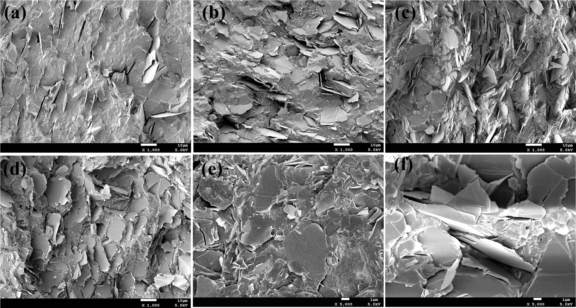
The SEM images of the fractured surface of (a) BNNS10, ×1000 (b) BNNS20, ×1000, (c) BNNS30, ×1000 and (d) BNNS40, ×1000; The SEM images of (e) BN40, ×5000 and (f) BNNS40, ×5000. SEM: scanning electron microscope; BN: boron nitride; BNNS: boron nitride.
Melting and crystallization behavior of PA6 and its composites
Figure 7 shows the cooling and reheating DSC curves of the pure PA6, PA6/BN, and PA6/BNNS composites. For clarity, all of the DSC scan curves shown here were shifted vertically. PA6 and its composite samples containing various BN and BNNS contents were heated to 250°C and then maintained for 5 min to remove the previous thermal history. All of the melt samples were cooled to 50°C at 10°C min−1 as shown in Figure 7(a). It could be seen that, for neat PA6, only a melt–crystallization peak (T CC,1) (i.e. crystallization from the melt state upon cooling) was observed at about 186°C. For the BN- and BNNS-filled PA6 composites, T CC,1 shifted to a higher temperature, 192–194°C, due to the nucleation effect of inorganic particles. Interestingly, in addition to the main crystallization peak at T CC,1, a new crystallization peak (T CC,2) was detected at higher temperature for the composite samples, and its position gradually shifted to a higher temperature together with a steady increase in magnitude as the concentration of BN and BNNS increased. This indicated that the existence of T CC,2 was closely related to the addition of inorganic particles to PA6 matrix. The unusual crystallization behavior resulting from the addition of BN and BNNS was attributed to its high aspect ratio. Similar phenomenon was reported in PA6/clay nanocomposites. 39 The high aspect ratio of BN and BNNS providing ideal nucleation sites for polymer chains to tether and crystal growth became easier when thermodynamic driving force was available at higher undercooling. However, the crystal growth rate was very slow at higher temperature owing to low undercooling, and therefore only a small exotherm (T CC,2) was observed in DSC results for the composites. 40 The heterogeneous nucleation sites increased significantly with the increasing loading concentrations of BN and BNNS in PA6 matrix, and thus polymer chains were easily crystallized, resulting in a more significant T CC,2 peak. 41 It was clearly seen that the T CC,2 of PA6/BNNS was higher than that of BN-filled PA6 composites, which was attributed to the higher aspect ratio and nanostructure of BNNS.

(a) DSC cooling curves obtained from BN- and BNNS-filled PA6 blends and (b) DSC second-heating curves obtained from BN- and BNNS-filled PA6 blends. DSC: differential scanning calorimeter; BN: boron nitride; BNNS: boron nitride nanosheet; PA6: polyamide 6.
From Figure 7(b), it could be seen that all samples exhibited one strong melting peak (ca. 220°C). The melting peak at about 220°C corresponds to the melting temperature of a-form crystals of PA6. The nucleation sites provided by BN and BNNS seemed to be favorable to the formation of thermodynamically stable α-phase crystals of PA6. 42,43 Interestingly, a faintness of the shoulder peak appeared at 215°C in the melting curves for the composites is observed in Figure 7(b), which was believed that the introduced BN and BNNS had a suppression effect on the formation of the γ crystalline form crystals for PA6.
It can be seen that the incorporation of BN greatly affected the crystallinity of the PA6 matrix in Table 3. Increased crystallinity was observed for composites with the increasing BN-loading fractions. It was suggested that the BN flakes offered more crystallization sites in composites which aided the formation of PA6 crystals, leading to an improvement of the crystallinity for the BN-containing composites. However, for the BNNS-filled PA6 composites, the crystallinity increased or decreased slightly. The reason might be that BNNS was able to interact with the polymer chains more effectively, which constrained the movement of polymer chains. The higher aspect ratio of BNNS also contributed to the slight change of crystallinity.
Thermal conductivity of PA6/BN and PA6/BNNS composites
The TEF 34 was helpful to analyze the effect of organic particles on thermal conductivity of composites. As shown in Figure 8, the exfoliated BNNS was more effective in increasing the thermal conductivity of composite when compared with the BN control. At a loading fraction of 40 wt%, the TEF was 948% for PA6/BNNS composite, whereas it was only 785% for BN control. The high aspect ratio of BNNS was one of the most critical factors for the impressive TEF. It is believed that the controlled and regular shape will help the formation of the textured structure and facilitate the thermal conductive pathway formation. Additionally, strong interactions between the BNNS and matrix resulted in lower interfacial thermal resistance. Both of them are known to be vital factors for enhancing the thermal conductivity of polymer composites. The exfoliation of BN into single layer leads to a several-fold improvement of thermal conductivity. Compared to the previously published work, 44 in which generally more than 30 wt% BNNS are required to achieve a TEF of 316%, our results were quite phenomenal to be 556%. The high aspect ratio of BNNS rendered advantages in the formation of efficient conductive networks in the polymer matrix. The exfoliation of BN into smaller and thinner sheet led to the changing of the filler volume fraction even at the same weight fraction. The stacking density of BNNS was 0.2196 g mL−1, which was lower than that of BN (0.2719 g mL−1). As shown in Table 4, the filler volume fraction of PA6/BNNS was higher than that of PA6/BN at the same filler-loading fraction. The increased volume fraction was translated to the better construction of thermally conducting networks by the flakes.
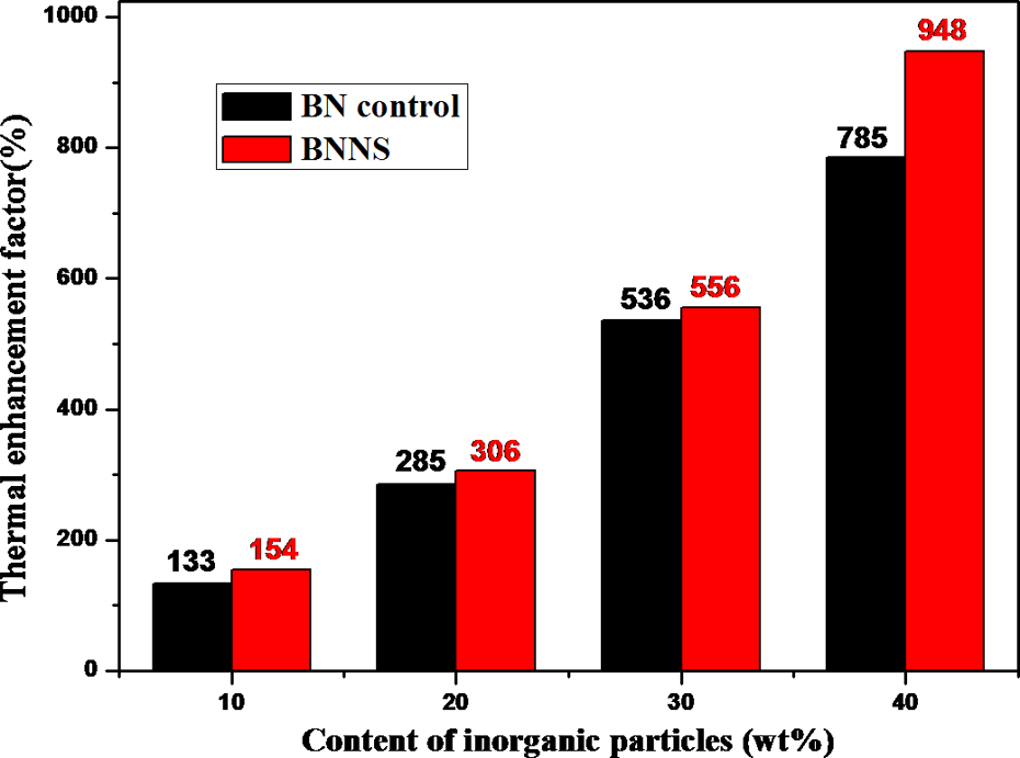
TEFs of PA6/BN and PA6/BNNS composites. BN: boron nitride; BNNS: boron nitride nanosheet; PA6: polyamide 6; TEF: thermal enhancement factor.
Furthermore, we noticed that the effect of using BNNS became more obvious. The TEF of BNNS10 was 154%, which was only slightly higher than the 133% of BN10. Basically, thermal conductivity of the composites increased slowly at low BNNS and BN loadings, which was mainly ascribed to the inadequate formation of thermally conducting networks by inorganic particles and the high thermal resistance generated from polymer matrix. 45
Mechanical properties of PA6/BN and PA6/BNNS composites
The effect of loading concentrations of BN and BNNS on the tensile strength of PA6 composites is presented in Figure 9. The tensile strength of BN-filled PA6 increased marginally with an incremental loading of BN when the loading fraction was less than 20 wt%. While at the filler loading higher than 20 wt%, the tensile strength decreased slightly. The reason might be that at lower loading fractions, BN sheets were rigid particles with high strength, and the strong interaction between PA6 and BN was contributed to the increased tensile strength. However, a plenty of defects would be formed by reunited BN blocks when high loading of BN was incorporated in host PA6 matrix, leading to a decrease in strength. In addition, it is clear from Figure 9 that the mechanical property of PA6/BNNS composites was higher than that of unfilled PA6. This indicated that the applied mechanical load could be effectively transferred to BNNS due to the profound interfacial interactions between PA6 matrix and BNNS. The present improvements in tensile properties were attributed to three factors. First, the distortions induced by exfoliation might result in wrinkled sheet topologies. Such nanoscale surface roughness enhanced mechanical interlocking with polymer chains. 30 The second factor was that, unlike the highly symmetrical C–C bonds, the B–N bonds possessed ionic characteristics, which might induce a polarized surface suitable for interacting with a polar polymer, for example, PA6 used in this study. The third was that perfect dispersion of BNNS in many organic solvents indicated that there might be some organic functional groups on their surfaces, which might interpret the interfacial interactions between PA6 and BNNSs.
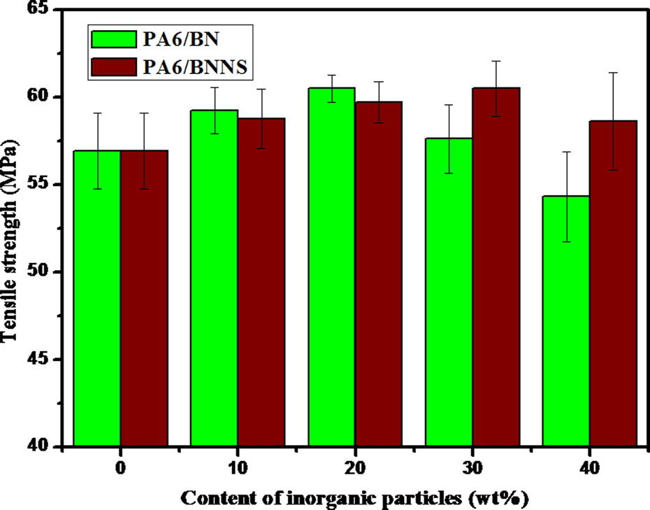
Effect of BN and BNNS content on tensile strength of PA6 composites. BN: boron nitride; BNNS: boron nitride nanosheet; PA6: polyamide 6.
Dynamic rheological analysis of PA6/BN and PA6/BNNS composites
The dependence of G′ (elastic modulus) and η* (complex viscosity) on angular frequency (ω) for the PA6/BN and PA6/BNNS composites are shown in log–log plots in Figure 10, respectively. The modulus value of the composites increased with the increasing filler amount in the entire range of frequency employed. It was clearly seen that G′ was sensitive to evaluate the rheological behavior of samples depending on the structural changes in the composites. The effect was even more pronounced at low-frequency region. The magnitude of the G′ increased and the slopes of the curves decreased at low-frequency region with the increasing filler content. Particularly, starting from 30 wt% particles, a plateau was found at low frequencies in G′ and a pronounced shear-thinning behavior was noticeable in η*. The relation was a well-known phenomenon for the composites, which indicated a physical network formation by the inorganic fillers. 46 The identification of the percolation concentration (φ c) could be performed in this figure using the rheological data. As shown in Figure 10, a change in the frequency dependence in particular at low frequencies was visible at varied BN and BNNS concentrations. Above this particular concentration, the rheological behavior changed from a viscous fluid to an elastic solid, indicating the well construction of the thermally conducting networks by the flake. The transition was observed at exactly the same composition as in the plots of G′ and η* versus frequency. It could be concluded that the thermal conductive network was formed near the concentration of 30 wt% BN or BNNS, or more specifically, between 20 wt% and 30 wt%.
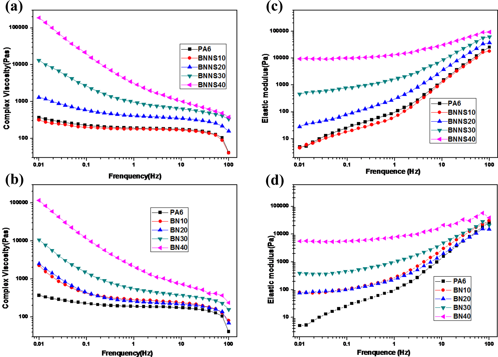
(a and b) Complex viscosity and (c and d) elastic modulus as a function of the angular frequency for different BN and BNNS contents for the composites at 250°C. BN: boron nitride; BNNS: boron nitride nanosheet.
Interestingly, the viscosity curves for BNNS10 composite demonstrated similar frequency dependencies as pure PA6, revealing a Newtonian plateau at low frequencies. However, this phenomenon was not observed for BN10 composite. It was well known from the literature that the interconnected structures and concentrations of anisometric fillers led to an apparent yield stress, which was visible in dynamic measurements by a plateau of G′ versus frequency at low frequencies and the shear-thinning phenomenon. 47 The shift and change in η* and G′ arose from the development of microstructure within BNNS10 composite.
Moreover, the G′ and η* at the lowest frequency applied
Conclusions
In this study, we reported a facile, scalable method to fabricate high concentrations of BNNS in IPA using sonication. The yield of final product with the thickness less than 20 nm is as high as 0.17–0.2 mg mL−1. SEM, TEM, and AFM measurements confirmed the successful exfoliation of BNNS and the thickness of BNNS mainly lies in range of several nanometers to 20 nm. BN- and BNNS-loaded PA6 composites were prepared by melt blending. Results indicated that the PA6/BNNS composites showed superior mechanical and thermal conductivity when compared to neat PA6 and h-BN-reinforced composites. At a loading fraction of 40 wt%, the thermal conductivity of the PA6/BNNS composite reached 2.496 W mK−1, which is 21.8% higher than that of BN-filled PA6 at the same filler-loading concentrations. In addition, it was noted that the tensile strength of all PA6/BNNS composites was higher than that of PA6, with a 6.23% enhancement at 30 wt%. Herein, the enhancement of the thermal conductivity and mechanical properties of PA6 composites were attributed to the higher aspect ratio of BNNS and the strong interaction between PA6 and BNNS.
Footnotes
Declaration of Conflicting Interests
The author(s) declared no potential conflicts of interest with respect to the research, authorship, and/or publication of this article.
Funding
The author(s) disclosed receipt of the following financial support for the research, authorship, and/or publication of this article: The authors would like to thank the National Natural Science Foundation of China (contract grant number 51273118) and the Science and Technology Pillar Program of Sichuan (contract grant number 2013FZ0006) for financial support and the Analytical and Testing Center of Sichuan University for SEM observations.