
Abstract
In the present study, computational fluid dynamics techniques are used to investigate numerically the performance of a heat exchanger (shell and helical tube) in order to improve its ability of transferring the heat through its body. The heat exchanger model includes a helical tube, a shell and baffles where the latter are of a cone shaped and distributed in the center and in the shell side. The angle and length of baffles are taken to be varied in the range of 0° to 90° and 10 cm to 35 cm, respectively. The major findings of the thermal analyses show that due to the baffles shape of the shell, the fluid moves inside the domain, with continuous baffles, and varies significantly, which is resulted in a significant increase in the heat transfer coefficient in the heat exchanger. The maximum amount of the transferred heat was obtained at the angle of 80° and length of 30 cm of the baffle.
Introduction
A device that transfers heat between two fluids at different temperatures is called a heat exchanger. Heat exchangers are the most important heat technology devices of the industry. Under different names such as evaporator, condenser, heater, cooler, etc. The main purpose of utilizing heat exchangers is to save fuel by making maximum use of heat energy. The measurements were made in the laboratory and Nu = 0.50 Re 0.55 Pr 1/3 (η/η w) of 0.14 (Re and Nu, depending on the shell side hydraulic diameter). As a result of this study, it was found that the heat transfer coefficient of the shell side must be dependent on the shell side hydraulic diameter. 1 Numerical studies have been conducted on the computational fluid dynamics (CFD) analysis to find the heat transfer rate and pressure drop of the water-based Al2O3 nano-fluid flowing through tubular heat exchangers in the helical tube. When Aly compared the results for the same Re or Dn, it is found that the heat transfer coefficient or heat transfer rate increased with increasing coil diameter and nano-particle volume concentration. At the same time, it is found that the friction coefficient increases with increasing curvature ratio and that the pressure drop problem can be neglected due to the nano-particle volume concentration increasing up to 2%. 2 Simulations were performed using different temperatures (hot fluid inlet temperature 25, 30, 35 and 40°C) and inlet coil fluid temperature 20°C. The results show that the performance of both heat exchangers is very similar at 25°C (hot fluid inlet temperature), but at 40°C the three-wire heat exchanger is more effective than the two-wire heat exchanger. It has been shown that performance can be improved by increasing the hot fluid inlet temperature with two and three helical pipes. 3 The modeling of the work was carried out by adhering to the principles of heat transfer, fluids mechanics and thermodynamics. With the application of boundary conditions and appropriate meshing selection, the results obtained are compared and validated with experimental results available in the literature. The results show that the heat transfer increases by increasing the internal Dean number, the inside diameter of the pipe, the curvature ratio, and reducing the pitch of the heat exchanger coil. 4 It focuses on the design of the horizontal shell and helical coil heat exchanger and its thermal evaluation of the reverse flow configuration. Thermal analysis; Such as cold water flow rate, hot water flow rate, temperature, effectiveness and overall heat transfer coefficient. They concluded that the design method results in sizing and grading analysis of the coiled tube heat exchanger and that the results are highly compatible with the experimental results. 5 In order to increase the surface area of the pipes, depending on the arrangement of the baffles, the baffles may be flapged or not flapged. The fins of pipes are used when the fluid heat transfer coefficient on the shell side is lower than the pipe side. 6
A computational analysis on the turbulent flow and heat transfer for water flowing in a geothermal vertical U-tube heat exchanger (GHE) has been carried out. The k-ε model of the work was described the turbulence phenomena, were solved by using finite volume method. The velocity and pressure terms of momentum equations were solved with SIMPLEC algorithm. The simulation of the dynamic and thermal behavior of the geothermal vertical U-tube heat exchanger was carried out under Fluent software. Results were compared with recent work from the literature and good agreement was obtained. 7 A three-dimensional (3D) numerical simulation of turbulent fluid flow and heat transfer in the shell side of a shell and tube heat exchanger (STHE) was investigated. Two primordial parameters were tested: baffles spacing of 106.6, 80 and 64 mm and six baffles orientation angles of 45°, 60°, 90°, 120°, 150° and 180°. The investigations were performed with the CFD COMSOL Multiphysics 5.1 software using the finite elements method, for Reynolds number ranging from 3000 to 10 000. The numerical results have been shown the important role of the studied parameters in the shell side thermal performance enhancement. It was seen that the baffle orientation angle of 180°, at 64 mm of baffle spacing was the best design that assures mixing flow, giving thus a highest value of thermal performance factor of 3.55 compared with STHE without baffles. 8 The idea of adding longitudinal fins on the inner smooth surface of the GHE's tube to ensure the better heat transfer was investigated numerically. The effects and the benefits of this new design of high density polyethylene (HDPE) finned tube was studied and the thermal and dynamic comportment of a typical vertical GHE was evolved. For this two different 3D numerical models having the same cell number, boundary and initial conditions representing respectively the smooth and the finned U-tube GHEs were constructed under the Fluent software, The model of the smooth U-tube GHE is validated by a comparison between its numerical results and experimental data. 9 A computational analysis of the natural ventilation process and entropy generation in 3D prismatic greenhouse was performed using CFD. The aim of the study is to investigate how buoyancy forces influence air-flow and temperature patterns inside the greenhouse having lower level opening in its right heated façade and also upper level opening near the roof top in the opposite cooled façade. The bottom and all other walls are assumed to be perfect thermal insulators. Rayleigh number is the main parameter which changes from 103 to 106 and Prandtl number is fixed at Pr = 0.71. Results are reported in terms of particles trajectories, iso-surfaces of temperature, mean Nusselt number, and entropy generation. It has been found that the flow structure is sensitive to the value of Rayleigh number and that heat transfer increases with increasing this parameter. Also, it have been noticed that, using asymmetric opening positions improve the natural ventilation and facilitate the occurrence of buoyancy induced upward cross air-flow (low-level supply and upper-level extraction) inside the greenhouse. 10
In this study, the cones in the different corners of the shell and tube heat exchangers were analyzed and analyzed with ANSYS program. At the end of the solution, the temperature, heat transfer and Nusselt number change in the heat exchanger are shown in diagrams. There are various works in this model related to the shell and the helical tube. The variation of pressure, velocity and heat transfer with respect to the change in length and angle of baffles were considered in the present study where the optimum value of the baffle angle, which indicates the maximum heat transfer, is determined.
Computational method
CFD simulation model
CFD is a working system that starts with the basic structure of the desired geometry and then unifies to model the desired area. In general, geometry is therefore simplified for CFD studies.
Modeling
In this study, a new shell type heat exchanger was designed and the simulation solution was implemented using the ANSYS program. In the study, newly designed baffles were placed in the center of the heat exchanger and around the coiled tube. The baffles in the center of the tube are designed as a conical shape, and the baffles around the coiled tube are designed as a conical part to direct the fluid. The corners of the Curtain are ranged between 0° and
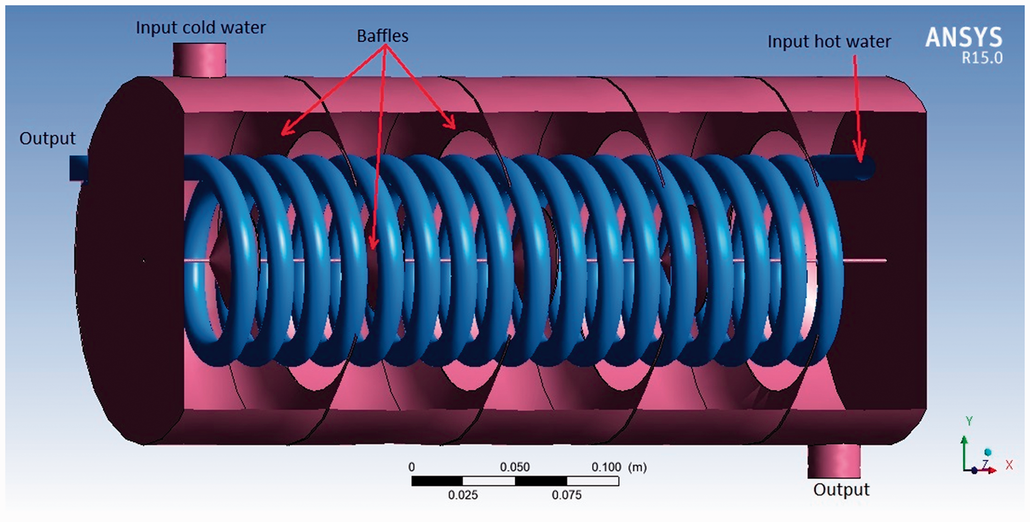
Computational model of shell and helical tube heat exchanger with baffles inclination.
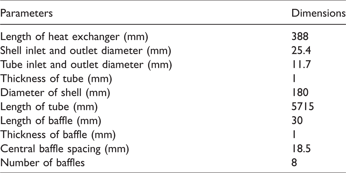
Geometric dimensions of shell and helical tube heat exchanger. 11
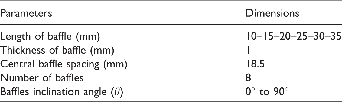
Geometric dimensions of baffles.
Meshing
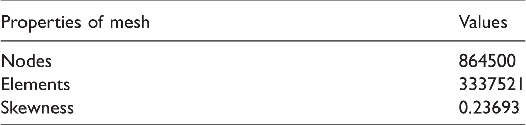
In order to ensure the accuracy of the numerical results, the grid independency test is conducted. A series of grid dependency tests were carried out to ensure that optimized computational mesh was obtained. The number of node points, number of elements and skewness average value of the meshing structure are shown in Table 3. The value of (y+= 163.85) for helical tube that lies in an acceptable range. 12 The histogram (Figure 2) explains the amount of grid efficiency and Figure 3 illustrates the mesh types used in the ANSYS program.
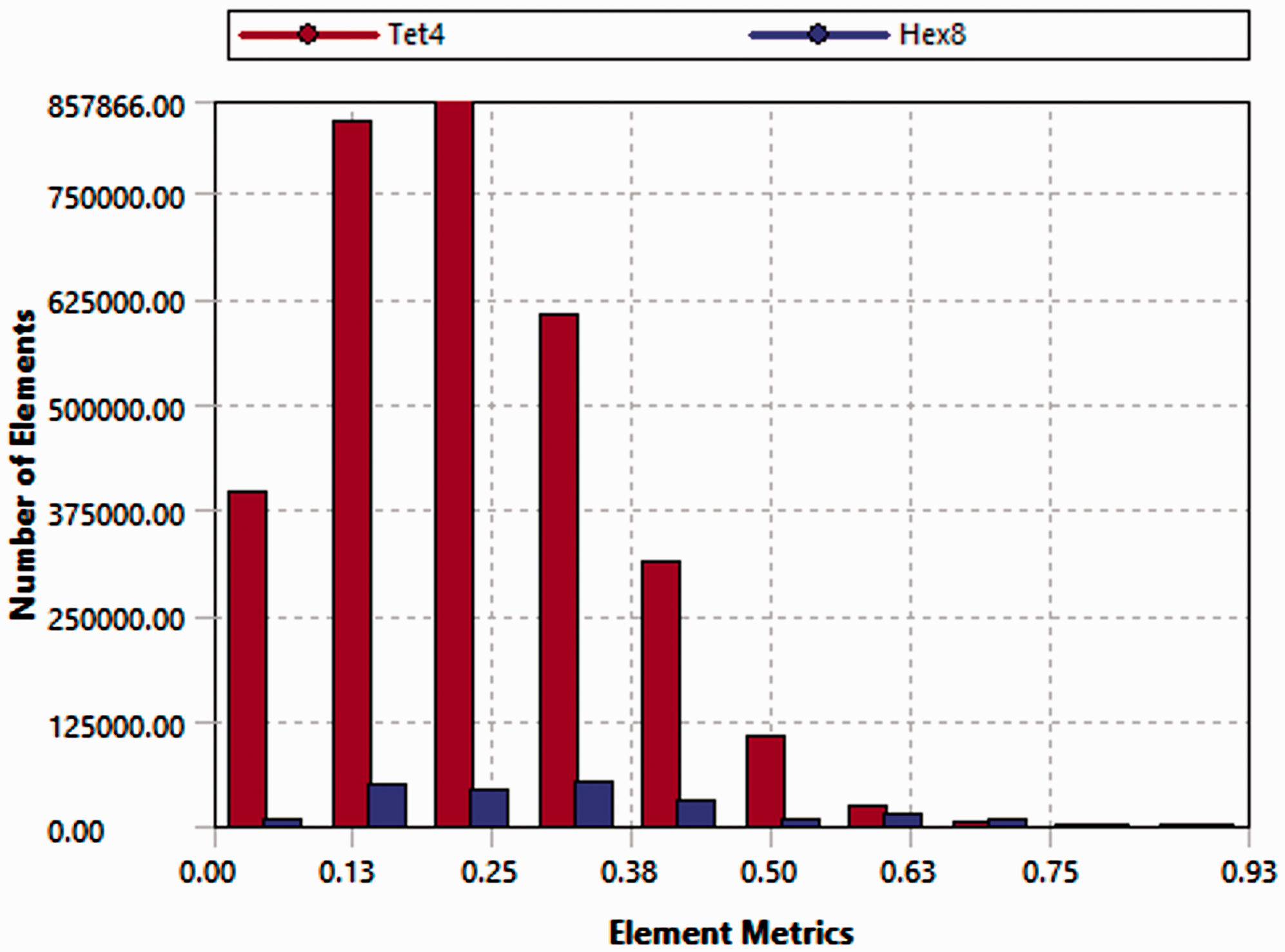
Mesh Metrics Bar Graph.
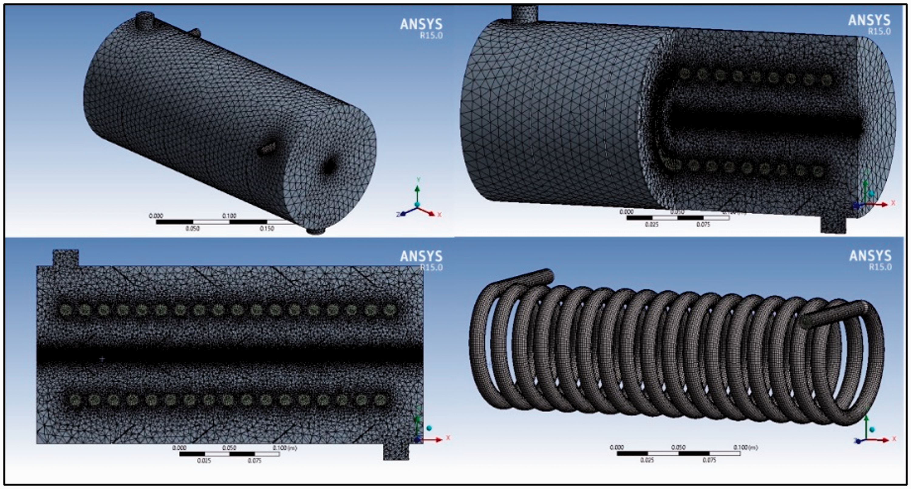
Meshing diagram of shell and helical tube heat exchanger.
Information about the meshing structure.
Governing equations
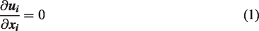
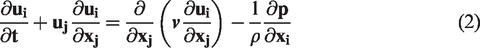
In this study, a hydrodynamic model based on the unstructured grid finite volume method was developed using the Fluent software. This model was based on the numerical solution of continuity, Reynolds averaged equation (RANS), momentum and energy equations. These equations are given below12,13
Energy equation
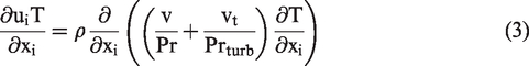
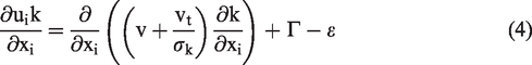
Turbulent kinetic energy k equation

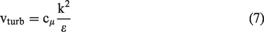
The turbulent kinematic viscosity is
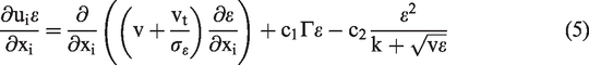
The empirical constants for the realizable k-ε turbulence model are

The scalable wall function is used for the numerical computation near the wall to avoid problems of successive refinements in standard wall function meshes.
Convective heat transfer equation

Data reduction
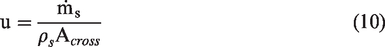
The mean shell side fluid velocity is defined by

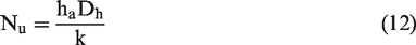
The Nusselt number for the annulus side is
Heat transfer rate of the shell side fluid (cool water)

Heat transfer rate of the tube side fluid (hot water)

Materials
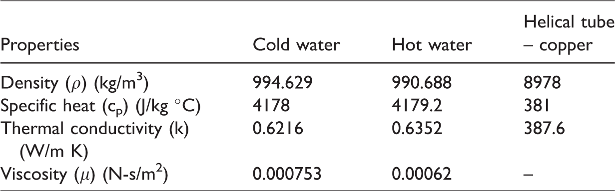
Then, the edit option is clicked to add the water-fluid (for hot and cold fluids) and copper (helical tube) to the list from the specified fluid database shown in Table 4 – fluid and solid respectively.
Properties of materials.
Boundary conditions
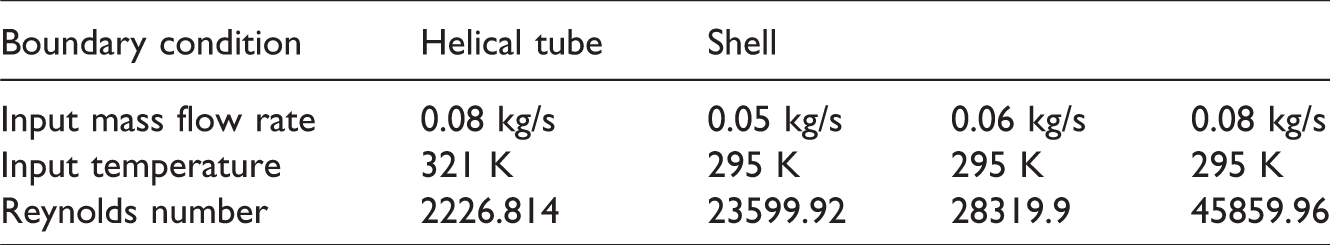
The momentum boundary condition of no slip and no penetration is set for all the solid walls. The thermal boundary condition of zero heat flux is set for the annulus side wall, while the walls of the inner tube and baffles have the thermal boundary condition of coupling heat transfer. These walls represent the solid–fluid interfaces between the two fluid domains and the solid domain (two interfaces with coupled wall). The inlets for the annulus and inner tube sides are set as boundary conditions of mass flow rate-inlet, the outlets are set as pressure-outlet. The outlets are assumed to have a pressure of zero so the inlet pressure is equal to the pressure drop on both the annulus and inner tube sides, as can be seen in Table 5.
Boundary conditions shell and helical tube.
Choose the solution method
In ANSYS Fluent, both the standard SIMPLE algorithm and the SIMPLEC (SIMPLE-Consistent) algorithm are available. SIMPLE is the default, but many problems will benefit from using SIMPLEC, particularly because of the increased under-relaxation that can be applied, A solution way has been chosen by limiting SIMPLEC from pressure-velocity, and leaving Skewness condition by default. Whereas, energy, momentum, and turbulent kinetic energy, the first order Upwind has been chosen.
Results and discussion
Fluent program results
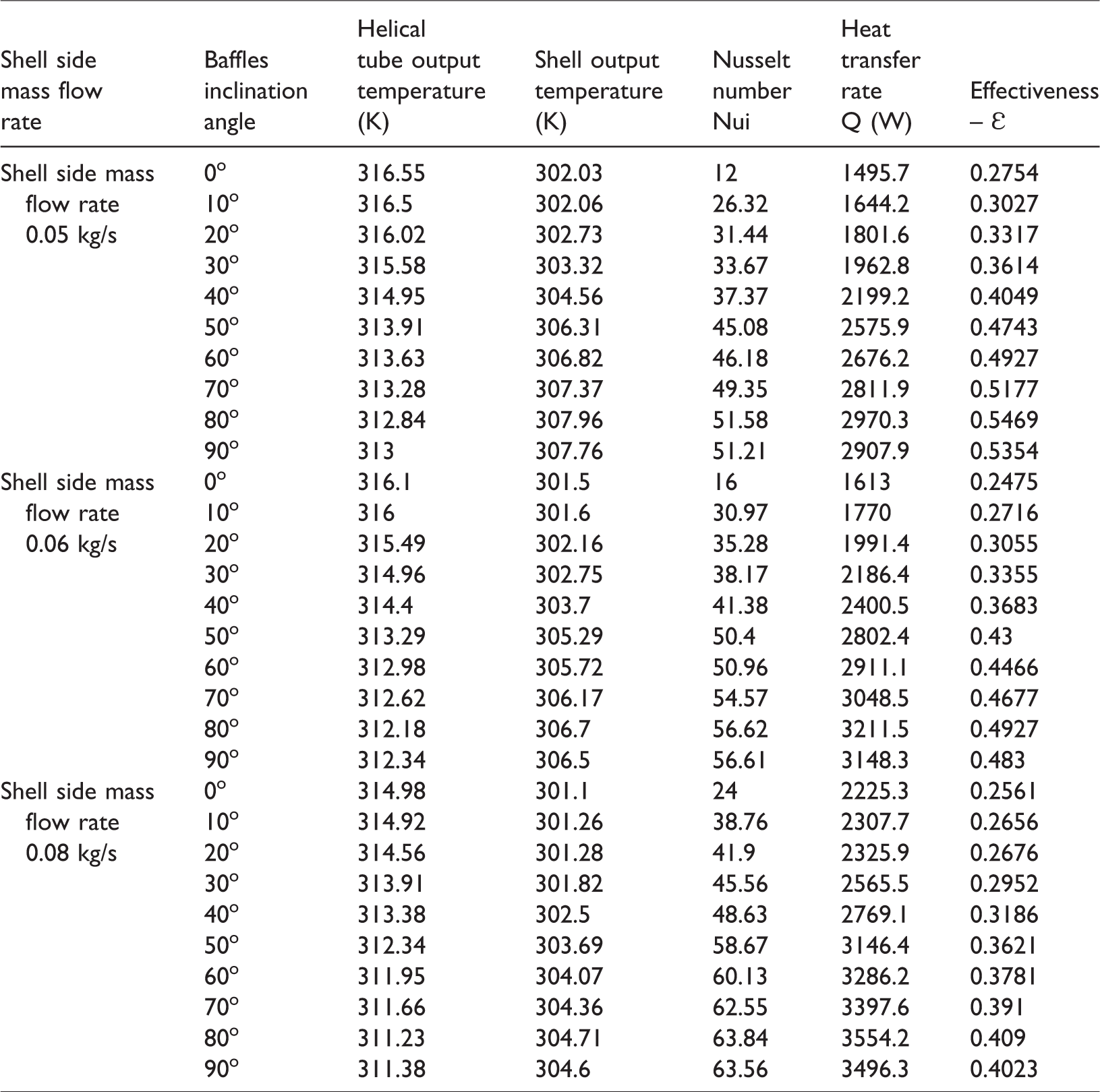
Data and schedules were obtained by analyzing the heat exchanger example in the Computational Fluid Dynamics Technique program. Table 6 contains the data obtained directly from the program. These data contain analyses of the temperature gradients of the helical tube and the shell, based on the mass flow average variation and the angle slope of the cone slabs.
Fluent program results.
Shell outlet temperature
In Figure 4, the temperature for the water entering the shell is 295 K, with the mass flow rates of 0.05–0.06–0.08 kg/s and the cone pitch angle of 0°–90°. As the inclination angle of the cone bevels increased, the temperature of the shell fluid increased. This increase in temperature is also observed in all cases of the mass flow rate used. The best temperature (307.96–306.7–304.7 K) and the slope angle were found to be 80°, respectively, with respect to the mass flow rate.
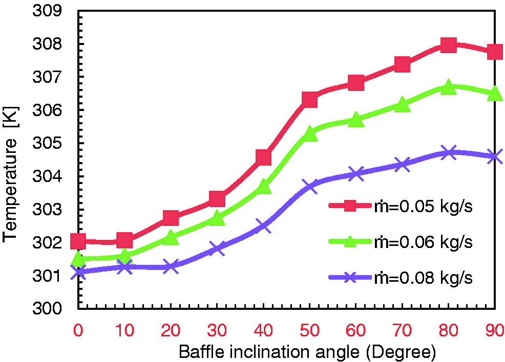
Shell outlet temperature.
Helical tube outlet temperature
Figure 5 represents the relationship between the temperature of the fluid exiting the helical tube (hot water) and the slope angle of the cone slopes, and shows that as the slope angle of the cone slopes increases, the temperature gradient decreases. At 80° of slope, the mass flow was found to be at the lowest level of the heat of the three states of mass flow.
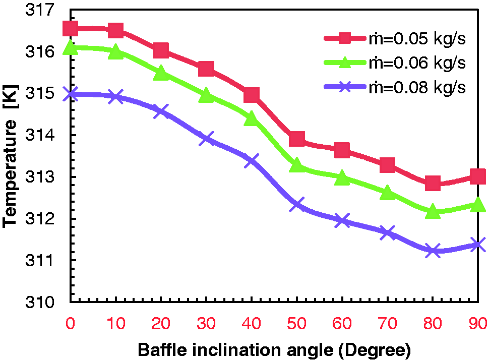
Helical tube outlet temperature.
Nusselt number
Figure 6 illustrates the relationship between the Nu numbers and the cone angle slope angle obtained directly from the CFD program. As the slope angle of the cone baffles increases, the Nu numbers rise and the rise rises homogeneously with temperature, as in other forms. The best Nu number was obtained at 80° angle slope and mass direction, respectively (51.58–56.62–63.84 Nui). We can see that these figures are the best when compared to other investigations, for example Andhare et al., 11 under the same conditions as heat gradients and cone flow except for baffles that distribute shell fluid only (as in Figure 7). And Figure 8, the flow of the fluid through the heat exchanger is shown in the figure. As can be seen, the movement of the fluid in the shell was observed as a laminate when the corner of the baffles was at 0°, and the fluid motion changed with turbulence as the corners of the baffles increased.
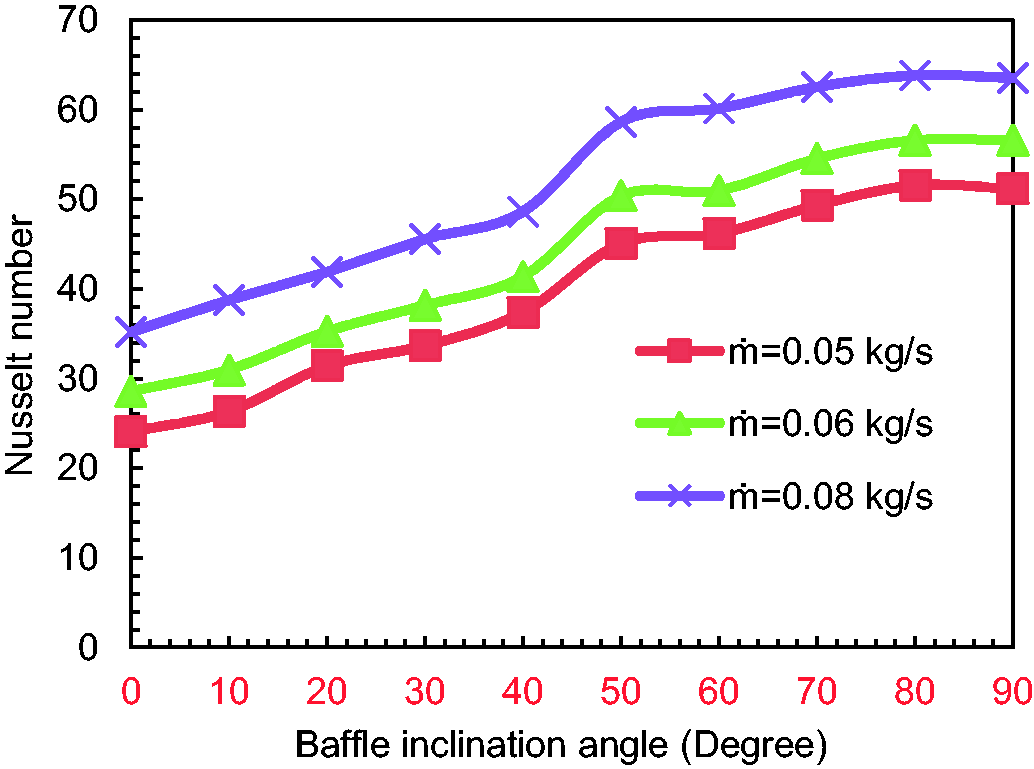
Nusselt number.
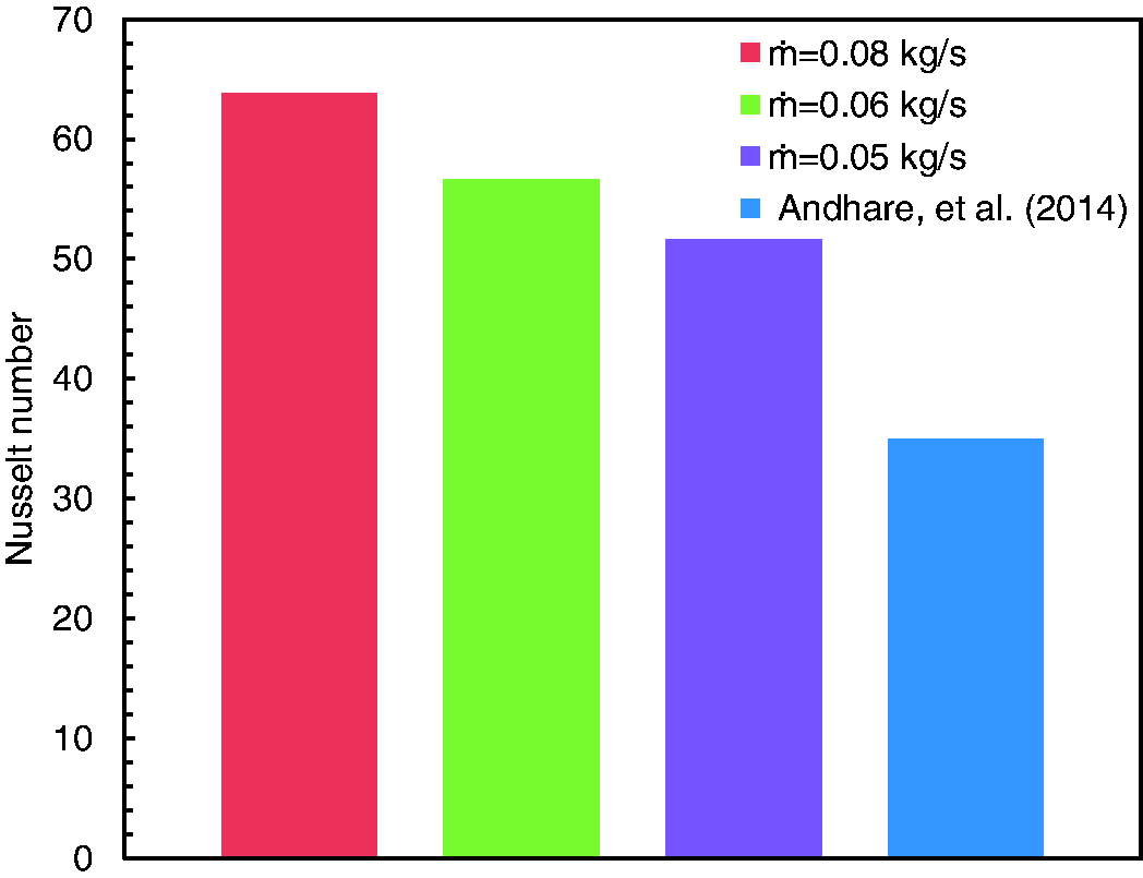
Nu is shown in the other research.
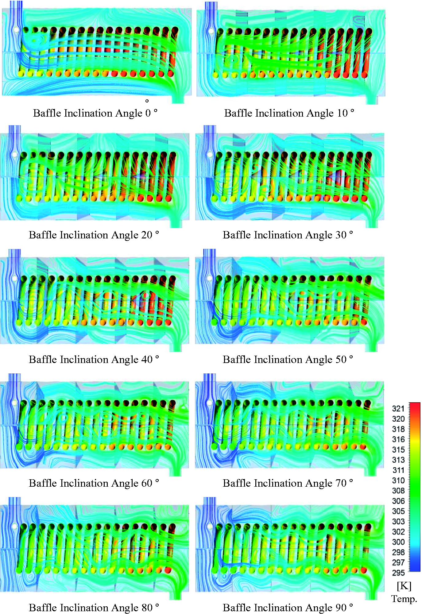
Temperature with streamlines distribution in heat exchanger with change angle baffles.
Heat transfer rate
Figure 9 illustrates the relationship between the heat transfer rate value and the mass flow rate of the shell fluid (0.05–0.06–0.08 kg/s) and the angle of cone slopes varying from 0° to 90°. Then, at the zero slope angle of (1495–1613–2225 W), the heat transfer value was obtained and continued to rise at an 80° slope with respect to the mass flow rate, reaching values of (2970–3211–3554 W), respectively. Due to these curves, a double heat transfer rate was achieved. And Figure 10 shows shell fluid and the helical tube show the temperatures of the fluid. The amount of temperature change between the two fluids in the figure is indicated by colors. It is also seen that the color of the fluid changes according to the angle of inclination of the cone baffles.
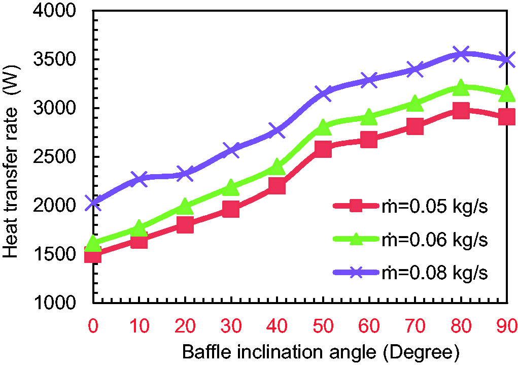
Heat transfer rate and curtain corner relationship.
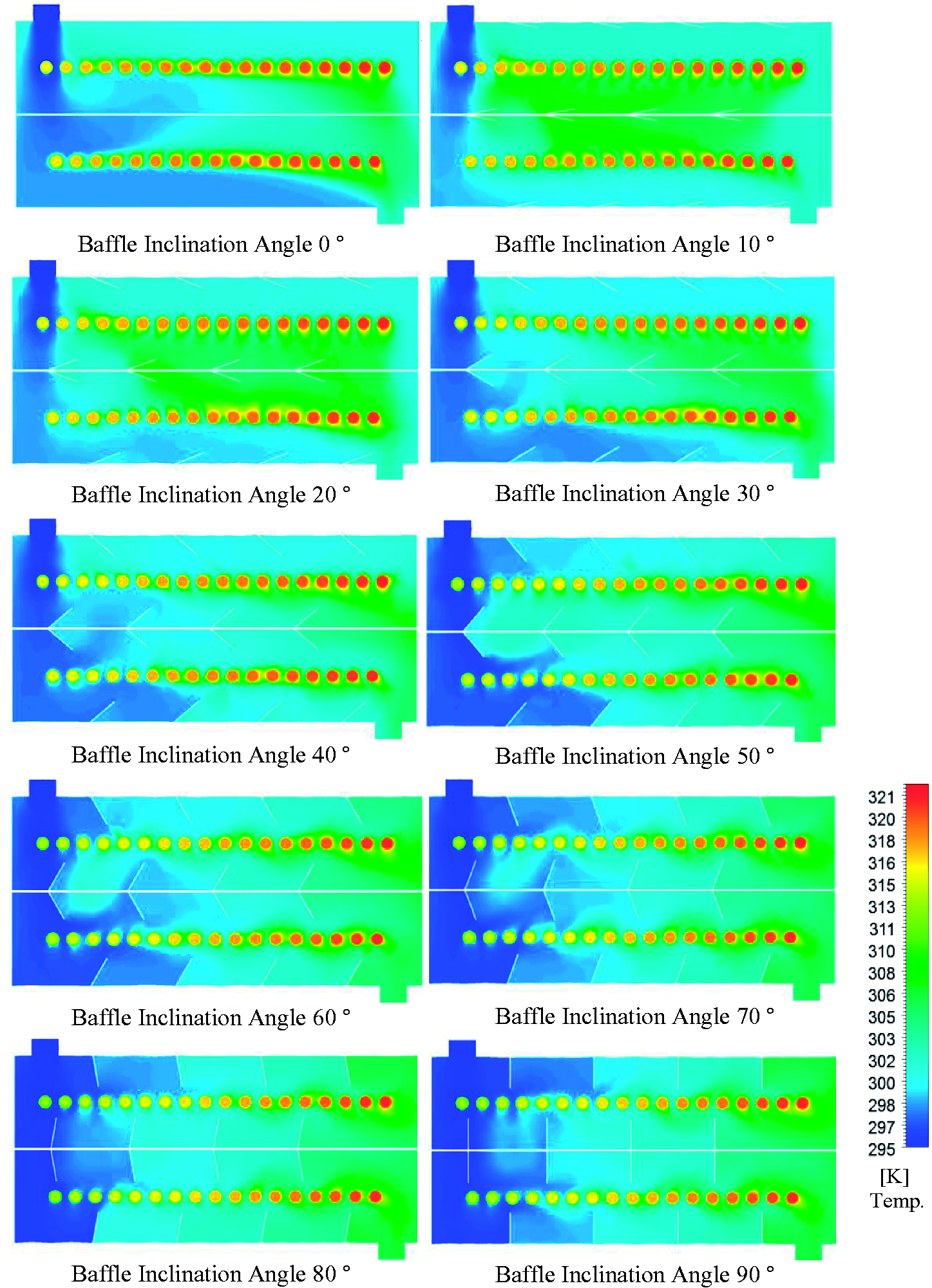
Temperatures distribution in heat exchanger with change angle baffles.
Heat exchanger effectiveness, ε
The heat exchanger effectiveness can be explained by the thermal performance of the heat exchanger and is shown by ε.
15
It is the ratio of the maximum heat transfer (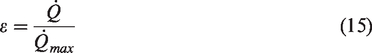

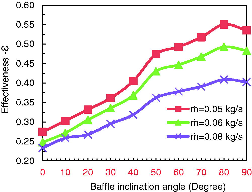
Effectiveness with change angle baffles.
Length of baffles
After defining the best angle of baffle of a cone shape, which was 80°, the effect of the baffle length on the performance of the heat exchanger is investigated by taking six different lengths starting from 10 cm to 35 cm with an increment of 5 cm. The simulation analyses are conducted by using ANSYS package. The obtained simulation results are shown in Table 7 and Figure 12 where the best baffle length is 30 cm.
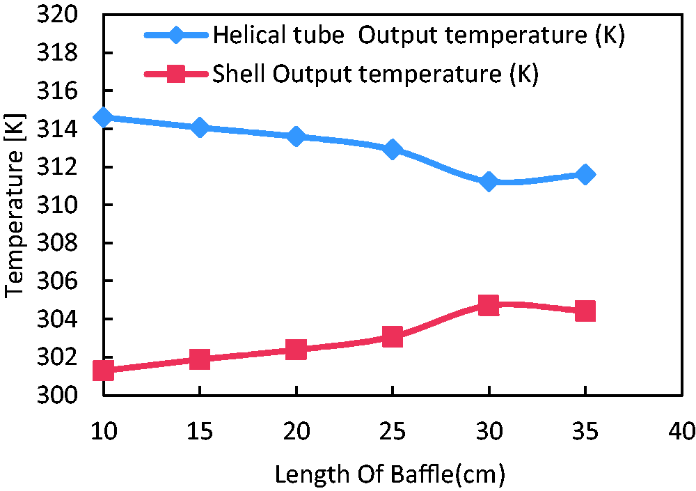
Temperatures with change length of baffles.
Fluent program results ‘temperatures with change length of baffles’.
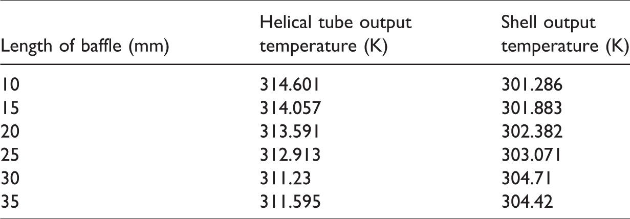
Figure 13 shows 10 longitudinal sections of the heat exchanger with different angles of baffle of
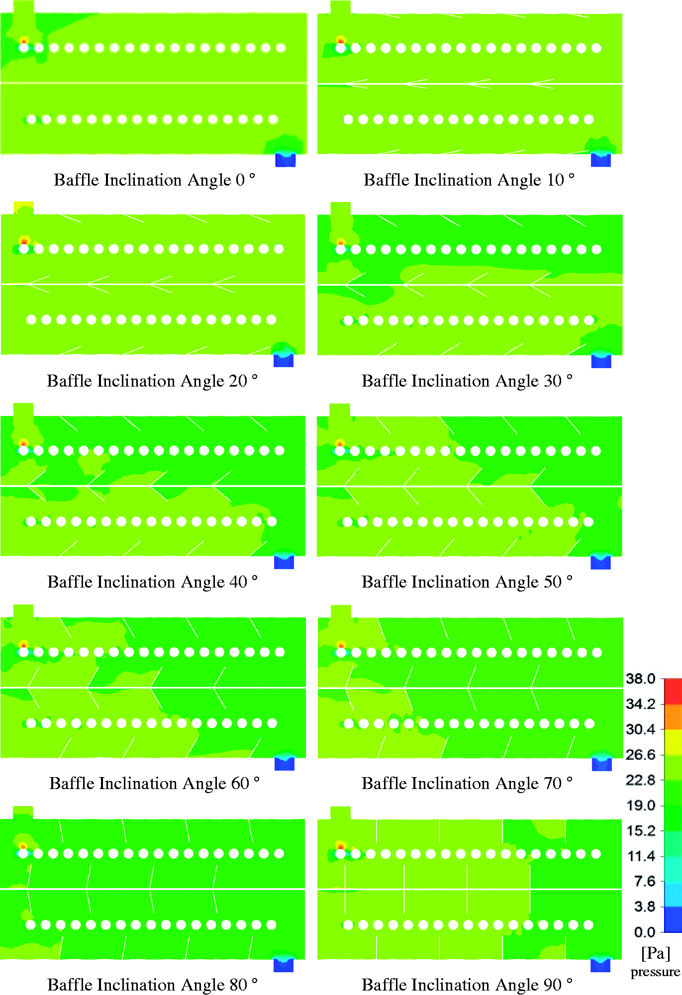
Pressure distribution in heat exchanger with change angle baffles.
Conclusions
In this study, the influence of cone baffles on the heat exchanger between fluids in the shell and helical tube type was investigated. The CFD technique was used to perform numerical analysis in the heat exchange study (CFD). The heat exchanger model includes a shell, a helical tube made of copper, and eight cone-shaped baffles distributed around the center and inside of the shell. The purpose of these baffles was to increase the performance of the heat exchanger between the shell fluid and the helical tube by increasing the distribution of fluid within the shell. The angles of the baffles are designed in the form of cones of a changeable angle of 0° to 90° with different lengths of 10 cm to 35 cm. In addition, with the inlet fluid temperature of (295 K) and the shell fluid with different three (0.05–0.06–0.08) (kg/s) mass flow rate, Helical tube inlet fluid were constant temperature and mass flow rate (321 K) (0.08 kg/s). According to the calculations made, the angle at which the best heat transfer takes place is determined.
The summary of the many important results we have obtained in the comparison of results in this study is as follows:
With the increase of the inclination of the cone baffles, the outlet temperature (cold fluid) of the shell fluid also increased visibly. The temperature of the helical tube fluid (hot fluid) decreased with the increase of the inclination of the cone baffles. This positively reflects the heat transfer rate, Nu and effectiveness values. When the inclination angle of the baffle's cone is 80° at a length of 30 cm, the best result was obtained in terms of the heat transfer rate, Nu and the heat transfer rate value according to the effectiveness values. The designing baffles increased the velocity of the fluid in the form of swirling flow in the shell, thereby providing a two-fold increase in the value of the heat transfer rate, since it allows the temperature to dissipate. Another meaning of this is to increase the distribution of the fluid in the casings and to direct the movement of the fluid well into the helical tube. This has improved the heat exchange performance and positively affected it. Therefore, in the heating process of the fluids with the heat exchange system, energy consumption is saved.
Footnotes
Declaration of conflicting interests
The authors declared no potential conflicts of interest with respect to the research, authorship, and/or publication of this article.
Funding
The authors received no financial support for the research, authorship, and/or publication of this article.