
Abstract
In response to the high NO x emissions and hopper overheating problem of a 600-MWe arch-fired furnace, a staged arch-firing framework (SAF) with an upper/lower staged hopper-air pattern was proposed to replace the original low-NO x technique. With implementing such a staged hopper-air configuration to enhance air staging and reduce the downward flame penetration, it was required to (i) affirm the SAF's effectiveness related to the mentioned problems and (ii) assess the upper hopper-air (UHA) angle effect for obtaining a reasonable UHA angle. Accordingly, the in-furnace flow, combustion, and NO x generation were respectively investigated under five UHA angles of θ = 0°, 20°, 30°, 35°, and 40°. Meanwhile, real-furnace tests and simulations in the original furnace were conducted to make comparisons with the SAF furnace. As θ increased, the flame penetration progressively deepened. The primary hopper-air function in favoring char combustion and overall combustion performance first strengthened and then weakened, while the production of CO and NO and combustible matter in fly ash first dropped and then ascended. The setup with θ = 35° demonstrated the most favorable low-NO x performance, exhibiting NO x levels of about 600 mg/m3 (O2 = 6%) and combustible matter of about 5% in fly ash. A comparison before and after the SAF application indicates that, despite reducing downward flame penetration, the SAF bolstered primary combustion and increased air utilization to facilitate char combustion in the hopper and the burnout zone. Consequently, a further 33.5% NO x reduction was achieved, along with slight burnout improvement and notably reduced hopper temperatures.
Introduction
As the primary environmental pollutants, nitrogen oxides mainly emanate from various coal-fired boilers that use coal as the principal fuel. 1 Due to various considerate design concepts, it was initially believed that arch-fired furnaces could establish a well combustion environment as industrially burning low-volatile coals. 2 However, due to the essentially poor combustion reactivity3,4 and rigorous NO x emission requirements, 5 arch-fired furnaces have universally deviated from the aforementioned performance, showing issues of asymmetric combustion, delayed ignition, inadequate burnout, weak combustion stability, and high NO x emissions up to approximately 1500 mg/m3 (O2 = 6%). 6
Great efforts have been devoted to the poor combustion issue. For example, in response to asymmetric combustion, Chen et al. 6 proposed a sidewall-dominated flame art to comprehensively improve combustion and furnace performance. Li's group 7 proposed an eccentric secondary air arrangement and modified secondary air to regulate well conditions below arches, whose industrial application in several large-scale arch-fired furnaces enhanced ignition and combustion stability during wide-load operations. The combustion retrofits 8 for regulating deep air staging in two 600-MWe low-NO x furnace, were confirmed to significantly drop NO x levels to approximately 860 mg/m3 (6% O2), with the combustible content in fly ash maintained at around 5.5%. Upon a new low-NO x system along with a gas-recirculating expansion strategy below the arches to stabilize combustion, Fang's group 9 gained a notable NO x reduction over 50% plus a slight burnout-loss increase in a 600-MWe furnace, with NO x levels dropped to 751 mg/m3 (O2 = 6%). For the bias combustion and air rearrangement from Zhang et al. 10 and the additional replenishment of a new low-load stable combustion technology, the related application in a 600 MWe furnace obtained a lengthened primary coal/air penetration depth, low NO x production, and high burnout. Obviously, the aforementioned reference review demonstrates great progress in improving combustion and lowering NO x emissions. Achievements include a substantial reduction in NO x emissions to approximately 800–900 mg/m3 (O2 = 6%) while maintaining the unburnt combustible in fly ash still higher within the range of 5–8%. Although conventionally deepening air staging could further reduce NO x to 600 mg/m3 (O2 = 6%) in the 600 MWe furnace, 8 the high burnout loss made this solution impractical in real-furnace operations. This means that the current low-NO x strategies, primarily based on the fuel-lean/rich bias combustion and air staging, still face the incompatible issue of poor burnout when attempting to achieve further lower NO x emissions.
Given the increasingly stringent NO x emission regulations, there is an urgent need for the development of more effective low-NO x techniques for the low-cost, in-furnace denitration for this type of furnaces. In response to the urgent requirement, a staged arch-firing framework (SAF) is devised in this work to resolve the identified compatibility issues. Three key strategies are implemented: (i) Reconstructing the furnace-arch arrangement to install two burner layers; (ii) Additionally introducing FGR and fuel reburning; and (iii) Meticulously redesigning the deep-air-staging pattern. This involves incorporating two secondary-air tiers, overfire air (OFA), along with the newly introduced hopper air (HA) and the elevated staged air, thereby forming the four air-staging layers. The staged hopper-air layout pattern is proposed for the SAF with the primary role of enhancing air-staging conditions by facilitating char combustion in the hopper. That is, the staged hopper-air pattern divides hopper air into two layers, where the upper hopper air (UHA) is positioned at the uppermost edge of the hopper and the lower hopper air (LHA) is situated in the hopper's upper part. This special UHA arrangement fates that the UHA angle should affect the SAF's low-NO x performance because an appropriate UHA angle is helpful to create benefits in four aspects of (i) extending the local reductive environment in the upstream to advance reburning, (ii) prolonging the coal/air penetration to improve burnout, (iii) strengthening the combustion-aided role of the UHA in the upper part of hopper for burnout, and (iv) forming a reasonable atmosphere to protect the hopper wall. Consequently, conducting a thorough investigation into the effect of the upper hopper-air (UHA) angle on low-NO x combustion becomes imperative. Subsequently, determining an optimal and reasonable UHA angle for the SAF is essential. Regrettably, the published literature to date lacks comprehensive studies on this subject. In light of this gap in the existing literature, our contribution to this theme involves the evaluation of a SAF furnace (modified from the original 600 MWe furnace in 8 ) at different UHA angles. The present work can fill the related academic gap in the published literature. In terms of our new contributions, the results from this study will (i) unveil the primary mechanisms of thermal-NO formation in the low-NO x SAF furnace when firing low-volatile and challenging-to-burn anthracite, (ii) establish the beneficial impact of judiciously enlarging the upper hopper-air (UHA) angle on furnace performance, and (iii) affirm the effectiveness of the SAF in addressing the aforementioned two issues. While the most important novelty of this work relies on the SAF's first usage of the staged hopper-air solution with the inclined UHA for (i) deepening air staging, (ii) shortening reasonably the downward flame penetration, and (iii) strengthening the UHA's combustion-aided role for burnout while remaining the LHA's hopper-protected function. The obtained findings also provide valuable insights that can serve as a useful reference for effectively regulating strengthened low-NO x and safe operations in arch-fired furnaces.
Boiler furnace and methods
600MWe boiler furnace before and after the SAF application
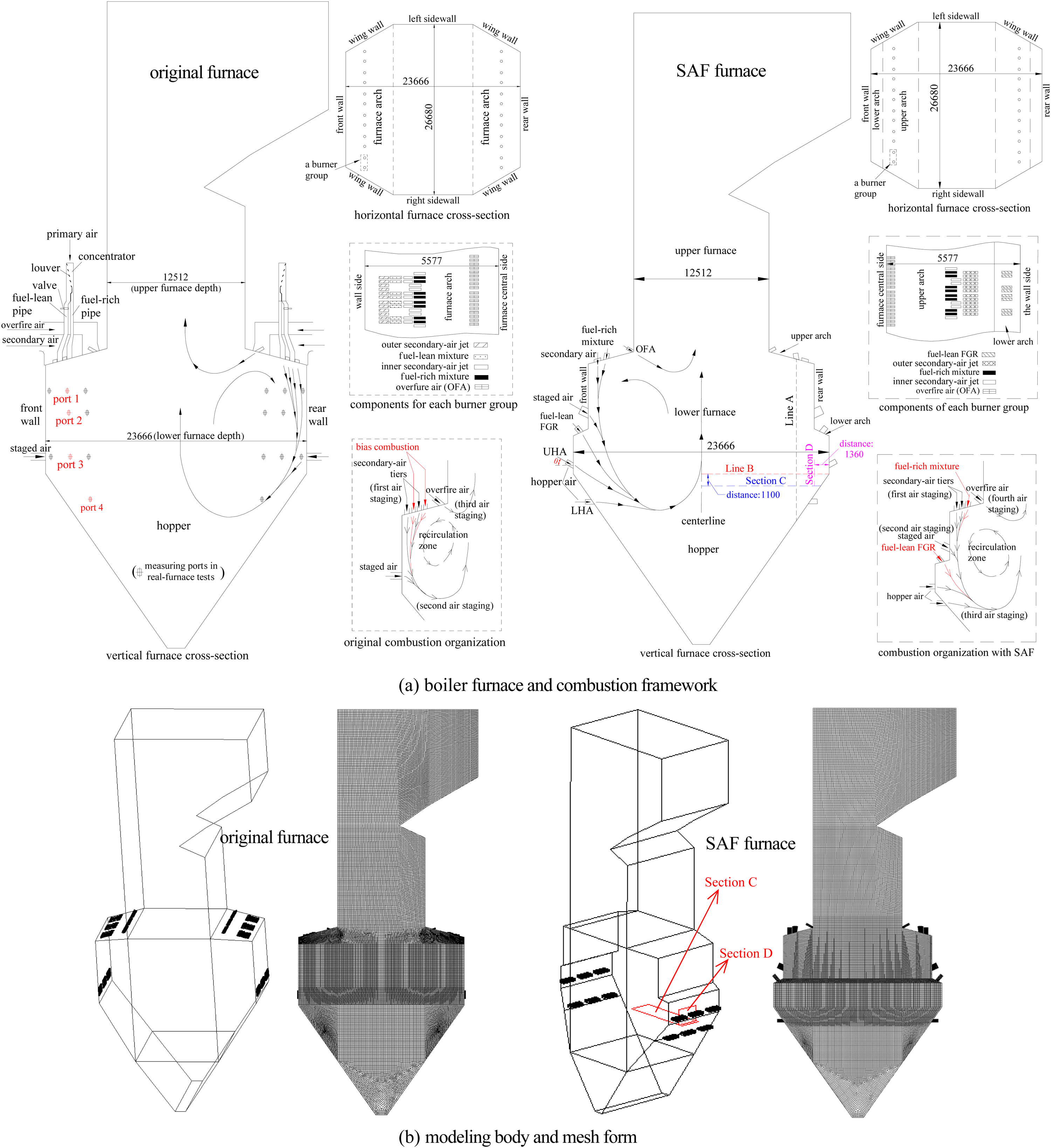
As previously stated, this study centers on the 600-MWe boiler furnace referenced as, 8 examining its conditions before and after the SAF implementation. Figure 1(a) and Table 1 illustrate the combustion arrangement, furnace structure, and the parameters of the 600 MWe furnace before and after the SAF. In the original furnace configuration, the primary function of the conventional front/rear furnace arches is to house secondary-air boxes and burners responsible for bias combustion. The low-NO x functions in this setup are solely attributed to deep-air-staging combustion and bias combustion. In comparison, the SAF furnace undergoes modifications in three areas: the furnace-arch structure, burner components, and combustion configuration. The staged upper/lower furnace arches are used to arrange respectively the primary and auxiliary burners. Two secondary-air tiers with air fluxes decreased, the elevated staged air, two hopper-air jets, and OFA sequentially constitute the four air-staging layers, effectively enhancing the deep-air-staging conditions. Auxiliary burners deliver FGR into the reburning zone, where the fuel-lean FGR is actually the mixture of the fine pulverized coal (originating from the previous fuel-lean mixture) and FGR. Consequently, the SAF furnace integrates an inclusive low-NO x framework characterized by enhanced deep air staging, rearranged bias combustion, and fuel reburning favored by FGR. In pursuit of further strengthening air staging, a staged hopper-air pattern is implemented. This pattern places the UHA at the uppermost edge of the hopper and the LHA at the hopper's upper part.
The 600-MWe arch-fired furnace before and after the SAF application.
Parameters in the 600-MWe arch-fired boiler furnace.
The investigation methodology used in this work refers to real-furnace test and numerical simulation. Real-furnace tests were conducted solely within the 600 MWe original furnace 8 for (i) providing an overview of coal combustion, NO x emissions, and performance indexes and (ii) verifying numerical simulations by comparing the real-furnace and calculated data. Subsequently, the validated simulation methodology was used to simulate the SAF furnace. In view of (i) the mentioned high furnace similarities (i.e., sharing identical main furnace configuration and dimensions but with the combustion system retrofitted for the SAF furnace) and (ii) the same simulation methodology used for both two furnaces, it is thought that the simulation methodology verified by the original furnace's real-furnace tests is reliable to simulate further the SAF furnace with varying the UHA angle.
Real-furnace tests and numerical modeling
Real-furnace tests were taken within the original furnace at normal full load. Data were primarily collected in three aspects: (i) Representative gas temperature for combustion symmetry. From the four rows of flame-viewed ports (Figure 1(a)) in the front/rear half sides of the lower furnace, an infrared thermometer (measuring range of 400–2000°C and an error of 0.5%) was utilized to measure the in-furnace gas temperature. To minimize the local combustion fluctuations on data reading, at each port a group of measurements were successively repeated within 3 min and the acquired data were averaged. At each measuring port, the acquired temperature was actually the highest data in the furnace zone sandwiched between the rightside wall and the near-wall burners; (ii) Near-wall gas temperature and component distributions at representative measuring ports. Given that the main downward flame passes sequentially through ports 1–4 along the flame travel, at ports 1, 3 and 4 gas temperature distribution was measured by using a thermocouple device (with an error below 8%). The thermocouple device actually had a 0.3-mm-diameter nickel-chromium/nickel-silicon fine wire positioned in a 4-mm-diameter stainless steel sheath as the key inner component and took a 8-mm-diameter and 4-m-length steel tube as its outer skeleton frame. Meanwhile, at port 2 the high-temperature gas samples were first pumped out through a water-cooled dual-duct probe. Regarding the probe configuration, a thin sampling pipe (having a gas flux of 1 L/min) was embraced by a 60-mm-diameter tube with a water flux of 60 L/min for cooling. The quenched gas samples were then analyzed on-line by a gas analyzer (Testo 350 with errors of ±5% for NO, ± 5 ppm for NO2, ± 0.2% for O2, and ±5% for CO) to obtain the local gas component levels; (iii) Major furnace performance indexes. During the real-furnace tests, samples of fly ash were collected from the air preheater outlet at an equal rate for obtaining the mean combustible content. A same gas analyzer was used to measure O2, CO and NO x concentrations in the exhaust gas at the air preheater outlet. It should be added that before the above real-furnace measurement, all instruments were checked and calibrated in accordance with industry standards, including comparing the readings of instruments with the known reference values and making necessary adjustments to ensure the accuracy and reliability of measurements. At the same time, during the real-furnace measurements, it was ensured that the position of each measuring probe was stable and in full contact with the gas in the furnace to avoid other interfering factors. For example, in light of any heavy soot or ash deposition on the thermocouple device apparently affecting its reading accuracy, during such temperature measurements the thermocouple tip was frequently examined and any depositions found were cleaned up. Prior to the measurement session, both the two gas analyzer had undergone zero and span calibrations with standard gas samples for ensuring the accuracy.
Modeling investigations were conducted for the furnace before and after the SAF applications. In the case of the original furnace, the simulation configuration remained consistent with the actual furnace setup. While for the SAF furnace, with the air/fuel parameters fixed (Table 1), simulations were conducted respectively at UHA angle setups of θ = 0°, 20°, 30°, 35°, and 40°. The definition of the UHA angle θ is graphed in Figure 1(a). The basis for selecting this UHA angle series relies on two aspects. First, the existing engineering experience and published works11,12 about the angle setups of wall-air jets in W-shaped flame furnaces, directly provide the primary guidance about how to set the UHA angle range and the angle interval for regulating the angle series. This is because the present UHA in its location and functions shows high similarity as the mentioned wall-air jets11,12 for air staging, where a conventional angle range of 0–45° has been trialed with large and small angle intervals of 10° and 5° respectively in the low and high angle levels. This study for setting the UHA angle series thus followed these criteria. Second, prior to the comprehensive simulations at the five UHA angles, a rough screening experiment (based on calculating only the airflow fields for comparing their symmetry and downward airflow penetration without combustion) extracted the UHA angle series of θ = 0°, 20°, 30°, 35°, and 40° with a well data trend and comparability.
Fluent 19.0 was applied to perform the above simulations. Figure 1(b) illustrates the computation furnace bodies and grid division forms, each comprising approximately 2 million cells. Information regarding the model selection and simulation setup is detailed below. The calculation models employed included the Lagrangian random particle trajectory for handling gas/particle flow, P1 radiation for radiation heat transfer, and realisable k–ε turbulence for gas turbulence. In the selected non-premixed combustion approach, the pertinent chemical reactions and turbulence were solved using probability density function theory. The devolatilization process was handled through the two-step competition method, while char combustion was modeled using the conventional kinetics/diffusion model. Given that nitric oxide constitutes over 90% of total NO x production in boilers and prompt-NO is typically neglected, the NO x calculation, using the post-processing method, considered solely the NO production via thermal-NO through the extended Zeldovich principle and fuel-NO on the De Soete's mode. By using the wall function method to calculate the fluid in the near-wall region, the no-slip wall boundary conditions were considered, with wall temperatures set at 700 K throughout the furnace. Given the temperature and velocity of the inlet fluid, the inlet conditions for burner nozzles and air ports were set to the uniform velocity inlet. The outlet conditions were set to the pressure outlet. The mentioned simulation methodology, along with the selected models, adheres to conventional practices and has been widely utilized, as detailed in.13–15
Due to the comprehensive low-NO x combustion organization in the SAF furnace, the overall combustion as the downward flame penetrating mainly undergoes in a reductive atmosphere with low oxygen (especially in the reburning zone). The adjustment of the UHA angle directly affects the O2 concentration and temperature distribution in the middle and lower parts of the reburning zone, which have a great impact on the local NO x and CO. Therefore, the generation and concentration change of NO x and CO were simulated to reflect the pulverized-coal combustion state and the prominent role of UHA angle. As for other pollutants such as SO2, its main source is the sulfur content in the fuel, which is greatly affected by the coal type and seldom varies with the operational parameters such as the staged HA. In the conventional boiler technology to reduce SO2 emissions, it mainly relies on fuel desulfurization treatment, fuel additives, and residual gas desulfurization. Clearly, the present UHA angle of the SAF is out of these desulfurization categories and conceivably influence little SO2 in the furnace. Consequently, both real-furnace tests and simulations only considered pollutant components of NO x and CO while no attention was paid on SO2.
Results and discussion
Experimental and modeling findings in the original furnace plus the simulation verification
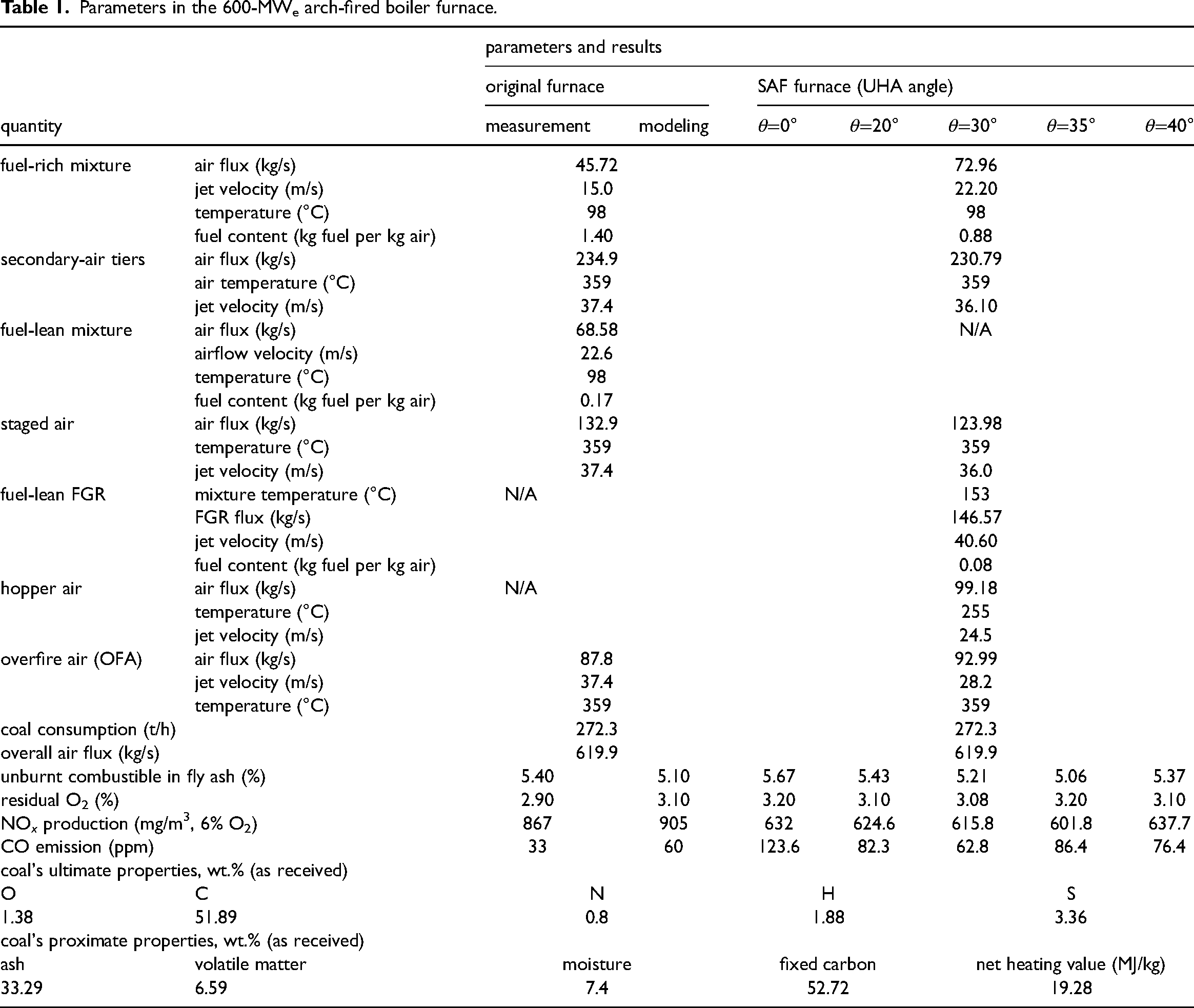
Panels 1–4 of Figure 2 present the industrial-size and calculated results in the original furnace. According to Figure 2(a), both the representative gas temperatures obtained from the real-furnace tests and simulations show a well-formed symmetrical form along the furnace centerline, indicating that symmetrical combustion occurs. It is explained by the symmetrical flow field (Figure 2(d)). With ports 1–4 positioned along the downward flame travel, data acquired through these ports denote the representative data in different combustion stages. Although both the measured and calculated temperatures follow their essence to show a normal up-to-down trend as combustion proceeds, temperature levels are still higher at ∼1200°C in the middle part of the hopper-wall zone implies an excessively deep flame penetration depth primarily favored by the robust secondary air (refer to the original secondary-air parameters in Table 1). Cold-modeling and real-furnace results of Song et al. 16 in the same furnace also confirmed the hopper's over-heating environment and its excessively deep coal/air penetration. Suppressed by the strong downward flame, staged air is redirected obliquely to form a relatively strong air layer (without entering into combustion) covering the hopper wall. Although this staged-air configuration appears effective in controlling air staging and safeguarding hopper walls, the persistently high temperatures in the hopper and the noticeably reduced share of staged air for char combustion pose potential risks to the safety and economy of the boiler furnace during its long-term operations.
Full-scale experimental and modeling results within the original furnace.
According to Figure 2(b), the near-wall gas temperatures corresponding to port 1 (in the burner zone) first raise and then drop as the probe is inserted. This can be attributed to the initial accumulation of high-temperature gases followed by the cooling impact of the low-temperature burner jets. Conversely, in the near-wall zones at ports 3 and 4, where primary coal combustion takes place and has nearly concluded, a significant amount of heat release leads to a continuous increase in temperature with distance. Consequently, the temperature order is port 1 < port 3 < port 4. As illustrated in Figure 2(c), trends in port 2 show the low and slowly-increased O2, relatively high and rapidly-increased CO, and relatively low and increase-to-decrease NOx. These patterns stem from the preceding deep-air-staging configuration, which notably prolongs the air/flame mixing in the previous combustion zone. This delay effectively suppresses the formation of fuel-NO, leading to low O2 levels and elevated high CO levels. Figure 2(b) and (c) also exhibit a good consistency between the simulated and measured gas temperatures and component levels in the near-wall zones, with calculation errors generally below 5%.
As indicated in Table 1, both the measured and modeled combustible levels in fly ash and NO x production are approximately 5% and 850–900 mg/m3 (6% O2), respectively. This merit regarding burnout and NO x production is explained by the deep-air-staging framework in Figure 1a and the calculated results in Figure 2(d). Nevertheless, this boiler furnace continues to face challenges related to poor burnout due to the reintroduction of deepened air staging and a heightened risk of thermal-fatigue in the hopper. 8 Evidently, additional efforts are required to attain enhanced low-NO x performance and mitigate the mentioned risks. In view of (i) the excellent consistency between the modeling and real-furnace results for the original furnace and (ii) the prior clarification regarding furnace similarities and simulation-verified relevance for cases before and after the SAF, the simulation methodology appears to be reliable for further simulating the SAF furnace while varying the UHA angle.
SAF's modeling results at different UHA angles
SAF's flow fields
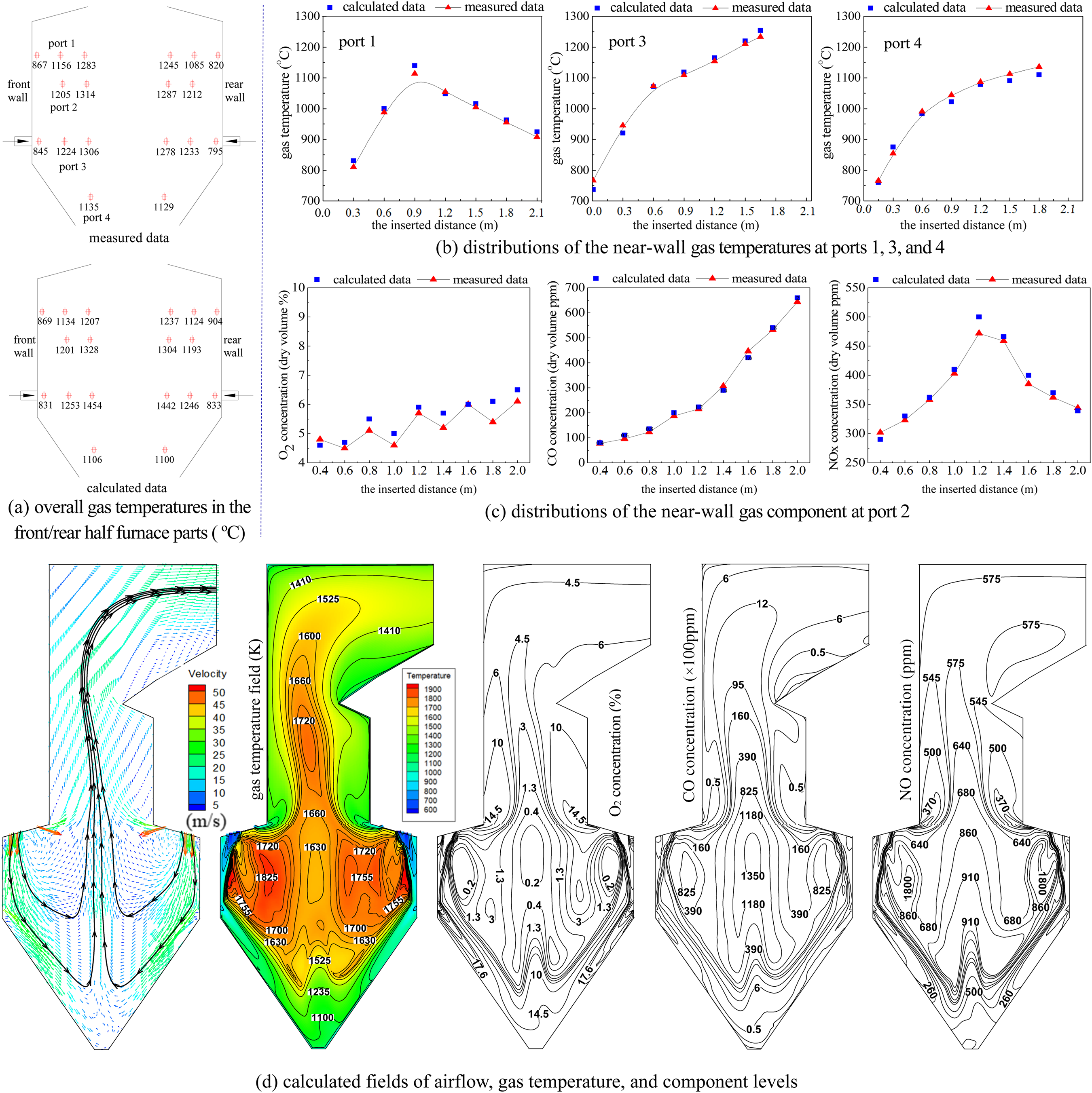
The flow-field diagrams of the five UHA angle settings are illustrated in Figure 3(a). In the burner zone and preceding combustion zone, the outwardly-inclined and low-speed primary flow is directed successively by the vertical and powerful secondary-air jets to form the downward flow. Subsequently, the inclined and high-speed staged air lengthens further the downward flow and meanwhile favors combustion, forming the second air-staging layer. In the lower-arch zone, the fuel-lean FGR merges into the downward flame. In the downstream of the reburning zone, the staged UHA) and LHA initially redirect and subsequently reverse the downward flame, additionally creating the third air-staging layer. Finally, OFA merges with the upward gas in the burnout zone, yielding the last air-staging layer. A pair of sizable and robust recirculation zones develops below arches. This recirculation process can favor ignition, combustion stability, and fuel-NO habitation below arches.
SAF's fields of flow, gas temperature and component levels at different UHA angles.
A comparison of flow fields (Figures 2(d) and 3(a)) before and after the SAF application implies the superiority of the SAF in four aspects: (i) Shallower but more effective downward flow penetration. Due to a higher downward coal/air momentum flow rate, the downward flow penetrates deeper in the original furnace than in the SAF furnace. Nevertheless, this prolonged penetration is likely to be ineffective for local char combustion; (ii) More air is used to favor char combustion in the hopper. As mentioned above, the original furnace actually enables a large portion of staged air to serve as the hopper-protecting function, failing to favor combustion. Contrastingly, the SAF furnace is designed to prioritize hopper air primarily for combustion while retaining an adequate hopper-protecting function through an effectively staged hopper-air configuration; (iii) Smaller but stronger recirculation zones below arches. Due to the reduced space between upper arches and shallower downward flow penetration, the large recirculation zones in the SAF furnace appear to be notably stronger compared to those in the original furnace. This change is beneficial for enhancing their functions in aiding ignition, stabilizing combustion, and reducing fuel-NO formation; (iv) Better OFA spread. In the original furnace, the OFA near the furnace throat shows poor OFA diffusion. In the SAF furnace, the OFA diffusion is stronger, contributing to improved burnout performance. This discrepancy arises because of different OFA locations.
For flow fields in Figure 3(a), the UHA angle obviously affects the downward flow penetration and the hopper-air behaviors. As the UHA angle increases, the mentioned flow penetration increases continuously, where the penetration-increase rate jumps in two end angle ranges (i.e., 0–20° and 35–40°) while shows low levels in the moderate angle range of 20–35°. Meanwhile, the air-layer strength and airflow velocities in the near hopper-wall zone initially decrease but then increase with the UHA angle. An explanation of these trends is listed below. In the SAF's combustion configuration with the downward momentum flow rate essentially lowered, the downward flame has already decayed sharply in the hopper and is thus hard to bear a strong transverse impulse of hopper air. This is due to (i) the continuous heat expansion of the downward flow and (ii) coal combustion significantly consuming the air with a high downward rigidity. The larger UHA angle, the lower UHA's horizontal interception on the downward flame. These are causes of the excessively short flame penetration that ends in the upmost part of the hopper at θ = 0° (i.e., the fully horizontal hopper air with the strongest transverse impulse). Such an excessively shallow coal/air penetration depth results in (i) only the UHA as the effective air supply for favoring char combustion in the hopper's upper part and (ii) a great share of the LHA only serving as the hopper-protecting air without attending char combustion in the downstream. Consequently, the air-layer strength and airflow velocities near the hopper wall are higher. Increasing the UHA angle in the moderate range of θ = 0–35° obviously weakens the hopper-air transverse impulse, allowing for an effectively lengthened coal/air penetration depth. These circumstances extend enough the downward flame travel and meanwhile make full use of the staged HA's dual functions. As a result, more hopper air participates in char combustion to weaken the air layer and airflow velocities near the hopper wall. Although increasing excessively θ to the maximum 40° lengthens further the main flame to approach the hopper's middle part, the sharply inclined UHA injection enables the UHA to mainly penetrate in the near-wall zone of the hopper. Consequently, a large portion of hopper air actually fails to enter into char combustion. These circumstances, on the contrary, are likely to weaken the final burnout. Based on the above UHA angle effect on the flow field mainly referring to the main flame penetration, the hopper-air share for char combustion, and the air-layer strength near the hopper wall, a reasonable UHA angle in the SAF furnace should be selected at θ = 30° or 35° among the five angle settings to balance well burnout and hopper safety.
SAF's gas temperature and component levels fields
Fields of gas temperature and component levels are illustrated in Figure 3(b)–(e). In various zones, including the upper part of the burner zone, the entire zone below the lower arch, hopper zone, the furnace-throat zone near OFA ports, and the near-wall zones in the upper furnace, there is a prevalent pattern of high oxygen levels and low levels of gas temperature, NO, and CO. The exceptions are the areas below the lower arch and in the upper furnace's near-wall zone, where O2 levels are low. These observations appear because of (i) the low-temperature injections of burner jets, the fuel-lean FGR, hopper air, and OFA and (ii) a combination of the local lower combustion fragments and the wall's heat absorption. Throughout the entire W-shaped flame travel, the primary combustion-undergoing furnace zones are consistently characterized by elevated gas temperature and CO levels, coupled with low oxygen content. In accordance with the zone shape and formation principle, the three distinct zones consist of two types: (i) A pair of large special zones symmetrically extending from the upper arches to the hopper's upper part, formed through the influence of the large recirculation zones (Figure 3(a)) combined with coal combustion in the surroundings; and (ii) A wedge-shaped special zone extending up to the furnace nose is present in the central part of the SAF furnace. Its formation depends on the prevalent upward gas flow and the residual char combustion in the upper-furnace zone. The higher gas temperature and CO levels, coupled with lower O2 and NO levels, in the former type of special zone compared to the wedge-shaped special zone can be attributed to (i) the inherent characteristics of the recirculating gas prevailing in the symmetrical special zones and (ii) significant combustion completion in the lower furnace. In the symmetrical special zones, spanning from the periphery to the central part, all data species, except O2, experience an increase. This phenomenon arises from the W-shaped flame travel, with combustion continually taking place, surrounding the symmetrical recirculation zones. The particularly high levels of CO (80000–110000 ppm) and NO (900–1500 ppm) are concentrated only in a pair of long and narrow zones, which span the preceding/primary combustion stages and are located between the circular special zones and the front/rear walls. Again, the local CO increases while NO decreases rapidly as the flame proceeds prior to the reburning stage, suggesting that thermal-NO is obviously inhibited. The reasons for these high CO/NO levels and the related trend are mainly because the local intense combustion rapidly consumes O2 to raise continuously CO and O2 is still sufficient in the preceding combustion stage, despite the SAF's enhanced air staging.
Comparing Figures 2(d) and 3(b)–(e) indicate that the SAF enhances low-NO x combustion primarily in three aspects: (i) The shallower flame penetration depth but with lower O2 levels. Typically, O2 levels in the circular special zones, hopper, furnace throat zone, and upper furnace are all lower in the original furnace than in the SAF furnace. These observations suggest that although the SAF achieves a relatively shallower flame penetration ending at the hopper's upper part, coal combustion is actually completed better than that of the original furnace, thereby consuming more O2. An explanation of this combustion improvement relies on a combination of the stronger large recirculating zones that favor combustion, the staged hopper-air pattern that strengthens the hopper-air function in aiding char combustion, and the reasonable OFA position that enables OFA to react well with the residual char in the burnout zone; (ii) Significantly lower temperatures, coupled with a still adequate oxidizing atmosphere in the hopper, are notable improvements. In the original furnace, the intensely high-temperature and high-oxygen environment (approximately 1600 K and 17%, respectively, see Figure 2(d)) in this hopper zone indicates poor utilization of staged air for char combustion in the hopper and an elevated overheating risk. Conversely, the SAF furnace exhibits significantly lower temperatures and O2 levels (approximately 1000 K and 10%, respectively) in the hopper zone. This indicates more efficient air utilization in the hopper for char combustion and eliminates the risk of hopper-wall thermal fatigue. An explanation of this improvement can be explained by a combination of factors: the enhanced deep air staging shortening the main flame penetration, the reduced combustion share in the hopper, and the staged hopper-air pattern that promotes char combustion while maintaining sufficient hopper protection; and (iii) Much lower NO formation throughout all combustion stages. Compared to the original design, the SAF consistently exhibits significantly lower NO levels throughout the furnace. This improvement can be attributed to a comprehensive low-NO x framework, including the deepened air staging conditions that further reduce fuel-NO, the supply of FGR that inhibits thermal-NO and reduces NO, and lower O2 levels in the burnout zone that once again inhibit NO formation. In summary, the comparison highlights the superiority of the SAF furnace in enhancing combustion, alleviating the hopper's overheating environment, and reducing NO production.
Figure 3(b)–(e) also illustrates the impact of the UHA angle on gas temperature and component concentration fields. As θ increases, although the downward flow penetration increases continuously, both the large circular special zones and the main flame penetration first enlarge and then shrink. Accordingly, the low-temperature and high-O2 zone first shrinks and then expands in the hopper, while the wedge-shaped special zone first strengthens and then weakens. Regarding the data trends with θ, in the large circular special zones gas temperature first drops and then raises while levels of NO and CO first raise before declining. On the contrary, data levels generally show opposite trends in all of the hopper, the wedge-shaped special zone, and the subsequent furnace-outlet zone. The above change trends in various furnace zone spans and data levels suggest that as UHA angle increases, coal combustion generally improves first but then weakens, while emissions of both CO and NO initially decrease but then increase, with θ = 35° as the turning point where the furnace performance begins to weaken. This means that θ = 35° should be selected as the appropriate UHA angle for upgrading the low-NO x combustion. Similarly to previous discussion about the flow-field trend, the above trends in various furnace-zone spans and the related data levels are mainly attributed to the fact that with lengthening θ, both the effective flame penetration and the hopper-air function in favoring char combustion initially strengthen but then weaken, generating an initial increase and a subsequent decrease in the whole combustion performance. Because of the enhanced deep air staging via the SAF, a more combustion fragment completed in an oxygen-lean atmosphere inhibits effectively NO production in the lower furnace, thereby showing a decrease trend of O2 and NO in an improved combustion performance. However, with excessively increasing θ to inversely weaken combustion (such as enlarging θ from 35° to 40°) results in weakened combustion before the main flame reversal. This inevitably increases refer to the portion or contribution of combustion in the burnout zone. Combined with the lower furnace's unchanged air supply and the burnout zone being solely aided by OFA, the overall combustion deteriorates, leading to increased emissions of CO and NO.
SAF's local data distributions are directly influenced by the UHA
For deepening the understanding about the SAF's UHA angle effect, in the rear-half part several local cross-sections and lines (Figure 1) are destined to compare the modeling data distributions. These consist of the horizontal thin Section C below the UHA ports, the vertical short Section D facing the UHA ports with a distance of 1360 mm, the vertical long Line A between the primary burner and the hopper wall, and the horizontal Line B below the UHA ports (connecting the hopper's upper edge and the furnace centerline).
Figure 4 presents the data distribution on the Section C where the downward flame initially reacts with the UHA and then reverses upward in the central part. From the side adjacent to the wall towards the centerline of the furnace, data patterns indicate an increase in temperature, NO, and CO while an oxygen decrease. This cross-section is fully filled with a small near-wall special zone and a large near-center special zone respectively corresponding to the UHA's dilution and the high-temperature flame reversal. The small near-wall special zone is characterized by low levels of gas temperature, NO, and CO, along with high oxygen, due to the initial dilution of the low-temperature UHA on the downward flame. In contrast, the large special zone towards the furnace center, which accounts for the major space of the Section C, shows characteristics of elevated gas temperature, NO and CO, accompanied by low oxygen, owing to the latter combustion-aided function of the UHA as the main flame reverses. With lots of char particles originating from the fuel reburning zone, the local char combustion aided by the essentially low-ratio UHA in the flame reversing travel is intense, thereby raising temperature apparently, consuming O2 sharply, surging CO significantly, and increasing NO levels. As the UHA angle increases, the small near-wall special zone shrinks and moves towards the wall side, with its temperature decreasing, O2 and CO increasing, and NO undergoing a decrease-to-decrease trend. Meanwhile, the large near-center special zone shows a shrinkage-to-expansion trend in its zone area and gradually leaves the furnace center. The local temperature data first elevate and then decline, NO generally presents an opposite trend as that of gas temperature, while O2 and CO respectively drops and rises. These trends with θ are explained through two aspects: (i) Increasing the UHA angle, on the one hand, enables the inclined low-temperature UHA jet to proceed towards the wall, on the other hand, decreases the UHA's interception on the downward flame, thereby weakening the flame tendency towards the furnace center before its reversal. Consequently, both the downward travel (related to the downward flame accompanied by the UHA) and the subsequent upward travel (related to the upward flame) in the hopper's upper part show a moderate tendency of moving towards the near-wall side (Figure 3(a)). Accordingly, either the small near-wall special zone or the large near-center special zone moves towards the near-wall side; and (ii) As mentioned and explained previously, with increasing the UHA angle, the overall combustion performance first elevates and then declines, while the NO production initially decreases but then increases. Consequently, θ = 35° shows the optimal performance among the five case setups. The local combustion improvement aided by the low-ratio UHA (Table 1) thus raises gas temperature, drops O2 clearly, increases CO significantly, and inhibits NO in the hopper. When excessively increasing the UHA angle to θ = 40°, a combination of the inversely shortened flame penetration in the hopper and the sharply inclined UHA primarily deviating from the downward flame (Figure 3(a)), finally lowers the local gas temperature. Here, the poor UHA support for char combustion drops again O2 and increases further CO. The essentially high NO levels in the upstream (Figure 3(e)) cause such a NO-increase trend with increasing θ from 35° to 40°. A consideration of a reasonable environment near the hopper wall and well combustion in the center side on the Section C prefers to set θ at 35°.
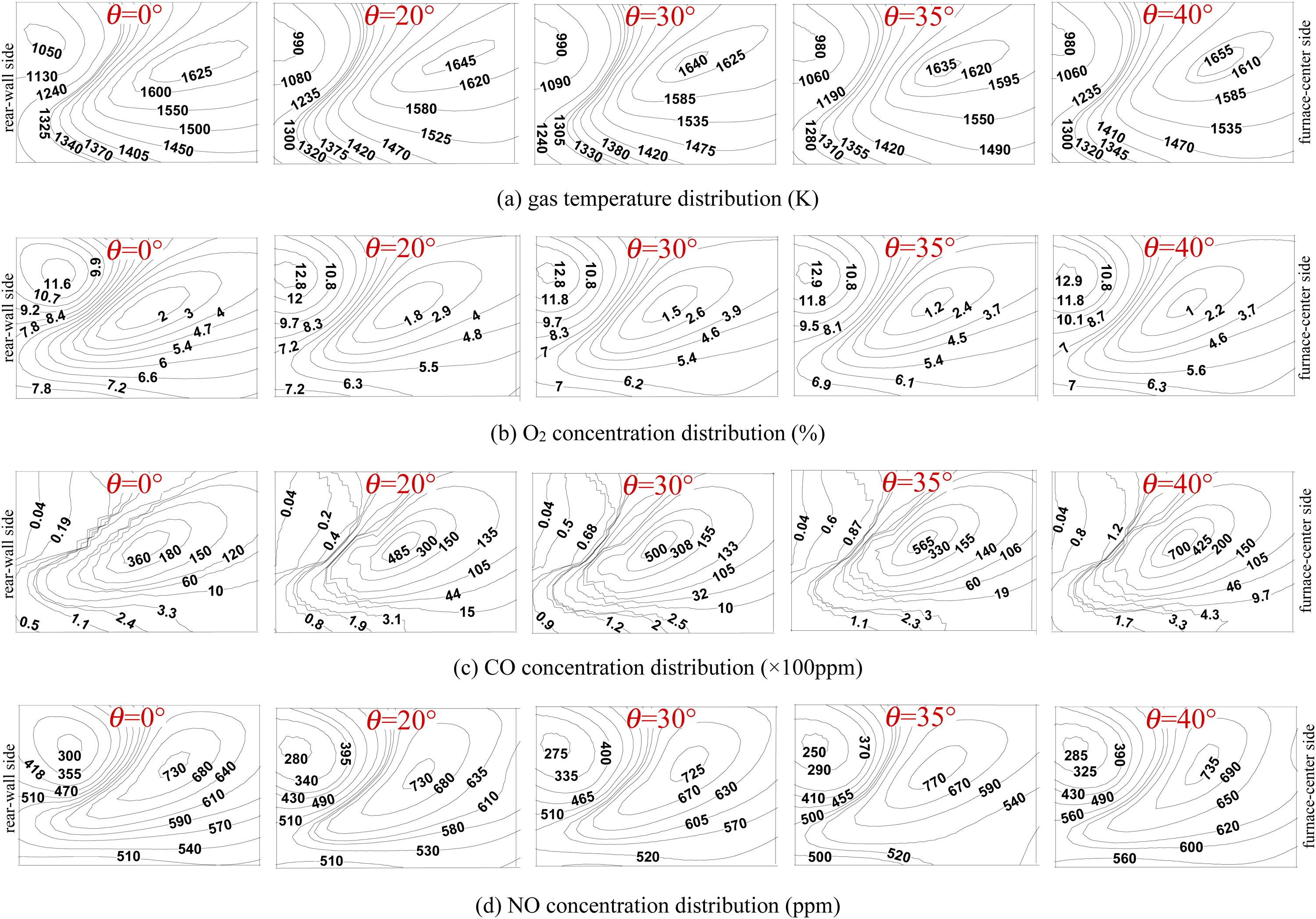
SAF's representative data distribution patterns along the horizontal Section C below the UHA.
Figure 5 exhibits the representative data distribution on the longitudinal Section D. The data distribution form on the Section D is characterized as a large central special zone (with high O2 and low temperature, NO, and CO) surrounded by two narrow special zones (with generally opposite data characteristics as those of the central special zone) respectively on the left and right sides. As the flame penetrates downwards along the Section D, there is an increase in both NO levels and temperature, a decrease in O2 levels, and the maintenance of low CO levels in the expansive central special zone. Conversely, data from the two narrow special zones typically exhibit opposite trends. These observations are explained by (i) positional relationship between UHA ports and Section D and (ii) the combustion of local char behaviors is facilitated by the UHA. As shown in Figures 1(b) and 2(b), with the Section D directly facing with the UHA ports, the UHA ports are positioned in a group pattern with a certain gap between any two neighboring groups. The Section D covers a little over a group of UHA ports in both the furnace height and breadth directions. These circumstances thus enable the UHA to dominate the major central zone and the gas to occupy the two narrow side zones, respectively. When the main flame moves to the large central zone, the UHA's mixing with the flame enhances the char combustion in the downstream, thereby raising temperature, lowering O2, and increasing NO to some extent. The local sufficient O2 and relatively low temperature thus keep the low CO levels and only cause a little NO increase. While in the two narrow side zones where the UHA is hard to diffuse, the reduced combustion as the flame approaches the hopper finally lowers both temperature and NO, increases a little O2, and decreases sharply CO. Figure 5 also shows that as the UHA angle increases, the dominant large central zone continuously moves downwards, with both gas temperature and NO showing a rise-to-drop trend while O2 levels displaying an opposite trend. These observed trends with the UHA angle occur because increasing θ not only delays the UHA's mixing with the flame on the Section D but also develops a rise-to-drop trend in the overall combustion (Figure 3(b)–(e)). In view of the important points that the UHA favors more char combustion in the downstream but with less CO and NO production, θ = 35° should be preferred as the optimal UHA angle among the five angle setups.
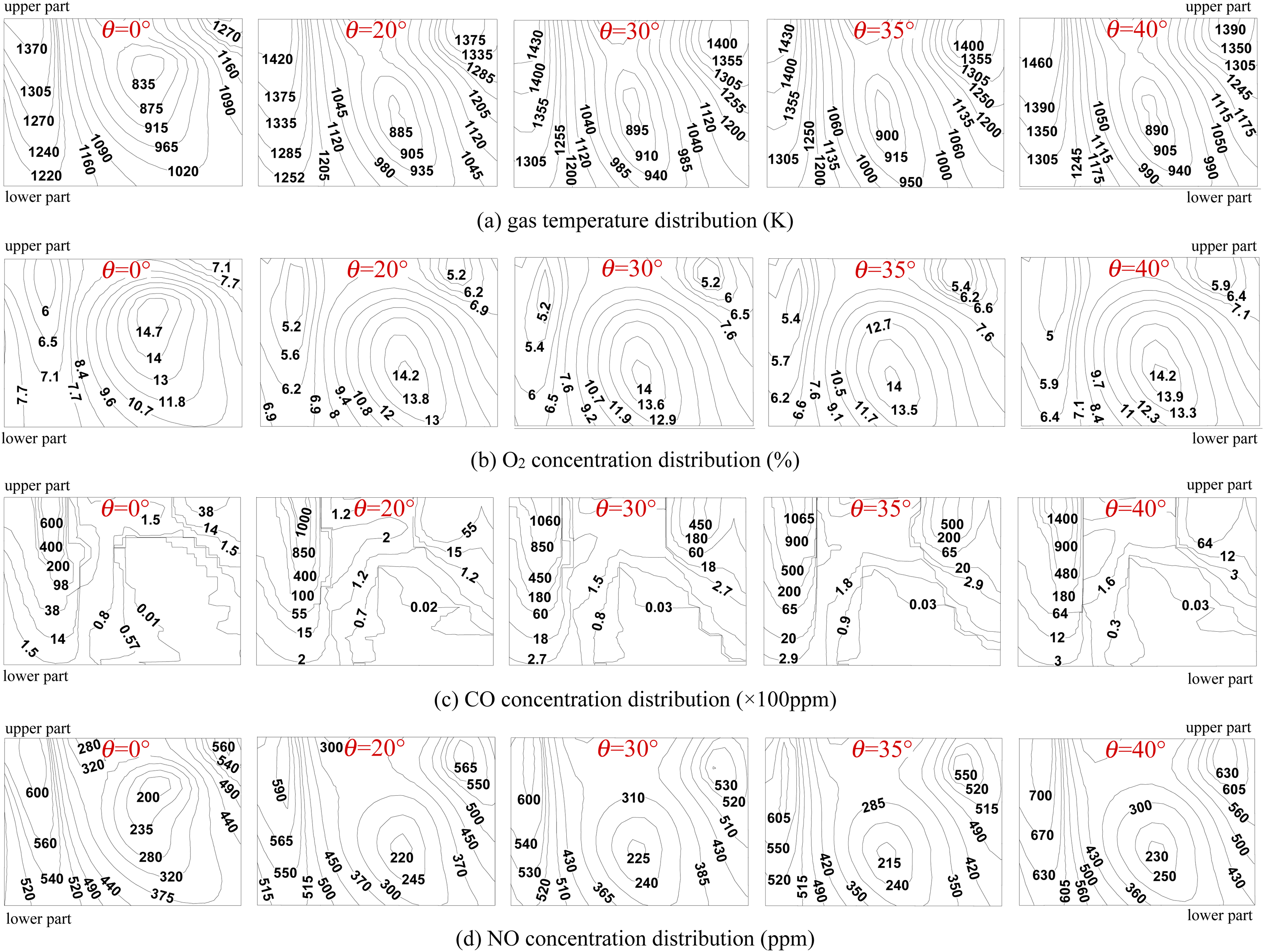
SAF's representative data distribution patterns along the vertical Section D facing the UHA.
With only gas temperatures and component levels involved, Figure 6 plots their data distribution curves along the aforementioned Line A. In each data panel of Figure 6, the longitudinal axis denotes the downward distance from the primary burner outlet. This means that in each data panel, the distance-increasing direction with the curves ascending from bottom to top actually corresponds to the downward flame's proceeding direction from the burner outlet. For all five angle setups, data curves along the Line A show a similar pattern in each panel, with the exception of some data variation. As the primary flame progresses downward (i.e., the curves ascend), the trends in the data levels can be summarized as follows. Temperature of gas shows two stages of increase followed by a decrease. O2 generally displays a dual pattern of decrease followed by an increase in the opposite direction. CO undergoes a substantial initial increase followed by a decrease, ultimately stabilizing at an extremely low concentration close to nil. NO initially fluctuates at low levels and then undergoes in turn a sharp and a small rise-to-drop stages prior to a continuous decrease. These data distribution patterns with combustion proceeding are explained below. For the preceding combustion stage below the upper arches, its good coal combustion status aided by the strong recirculating gas and the local reduced air supply, develop a sharp decline in both temperature and CO while a rapid decrease in O2. The local low-O2 and high-CO reductive atmosphere thus greatly inhibits the fuel-NO formation. Afterwards, with the main flame passing over the primary combustion and reburning stages, CO sharply decreases while gas temperature and other components all elevate initially but then descend. Reasons for these trends are depended on the staged-air injection for enhancing combustion in the upstream and the fuel reburning in the downstream. Initially, the staged-air injection enhances coal combustion to raise gas temperature and O2, where the local high-oxygen atmosphere sharply reduces CO and boosts the thermal-NO production. Here the NO distribution along the Line A suggests that with the SAF, the fuel-NO is significantly suppressed in the upstream while particularly high thermal-NO levels occur in the downstream. Subsequently, the fuel-lean FGR delivery (used for the endothermic fuel reburning reaction on the NO reduction) generally results in gas temperature and species levels decreasing with different rates. In the hopper with a limited char combustion fragment, where the UHA mainly enhances combustion and the LHA focuses on the hopper protection, both temperature and NO levels first ascend to some extent and then descend rapidly, accompanied by an opposite oxygen trend. The O2-rich environment and the presence of a limited combustion zone after the reburning stage, enable the extremely low levels of CO to vary slightly for a long time.
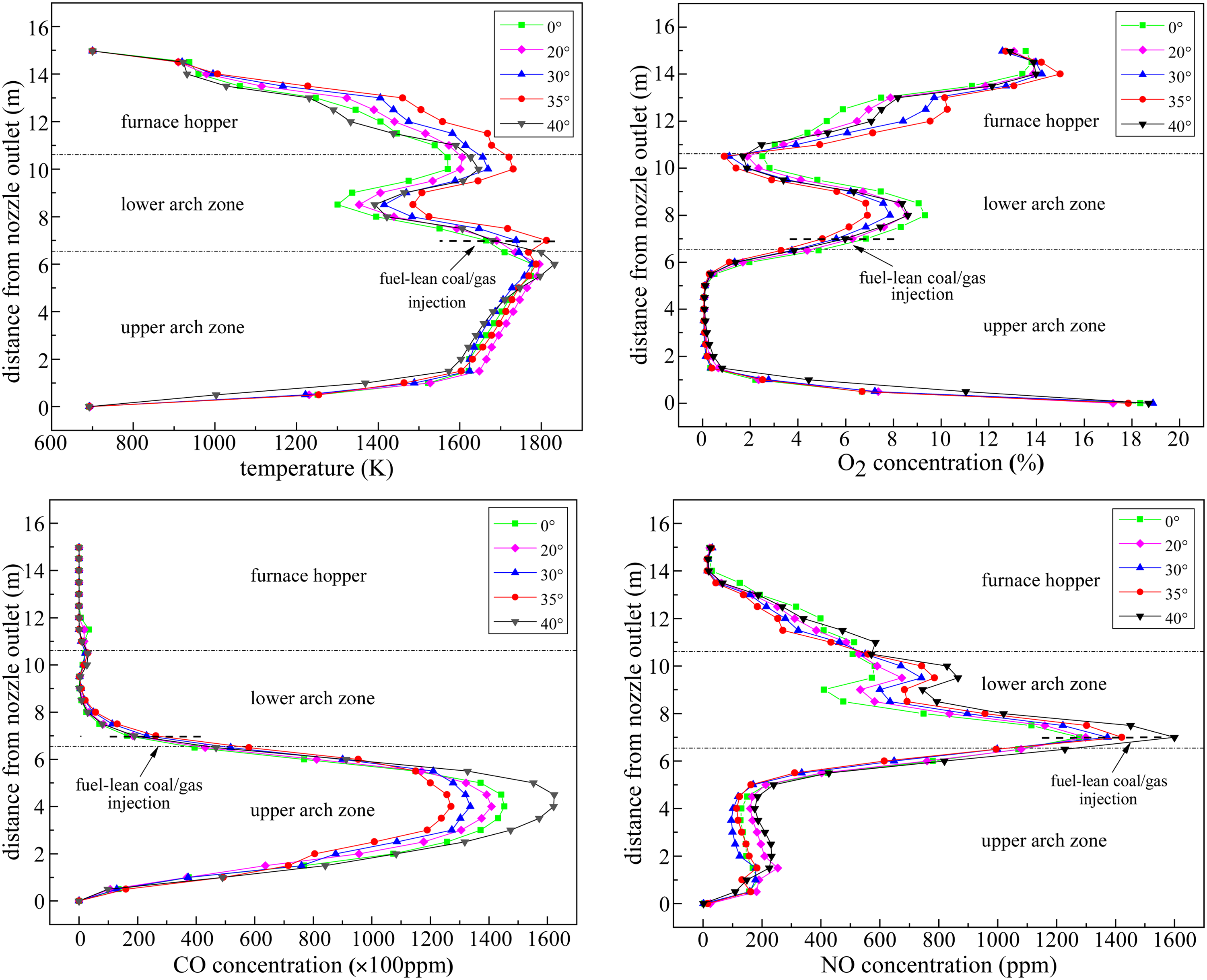
SAF's representative data distribution patterns along the longitudinal line A.
Figure 6 also shows the UHA angle effect on the data distribution along the Line A. As θ increases, these curve trends plus their related explanation are presented below. Gas temperature generally increases first before a subsequent decrease, while oxygen initially undergoes a drop-to-rise trend prior to the hopper and then acquires a general increase trend. This is owing to (i) the overall rise-to-drop combustion performance in the furnace (Figure 3(b)–(e)) and (ii) the continuously delayed mixing and reaction of the UHA with the char which essentially has a function in raising the local O2. The CO variation with θ mainly exists below upper arches, where a drop-to-rise trend first appears in the preceding combustion zone and then the trend reverses to an opposite form in the downstream. The former CO trend occurs because as θ increases, combustion initially strengthens but then weakens based on variations in the flame penetration and the large special zones below upper arches (Figure 3(b)–(e)). In the preceding combustion zone with an extremely low-O2 environment, high temperature, and good combustion status, a combustion elevation usually decreases the local CO and vice versa. The latter CO trend is attributed to the fact that as θ increases, the delayed UHA's merging with the main flame prolongs the reductive atmosphere range and lowers the local O2 from the reburning zone, thereby raising a little CO. However, at the largest angle of 40°, the weakened combustion plus a decrease in the effective flame penetration depth allows more residual O2 to drop the local CO. The NO trend with θ contains several stages below. First, low NO levels (about 200 ppm) vary slightly in the zone just below upper arches. Second, the subsequently surged NO shows a drop-to-rise trend. Third, in the overall NO-decline stage from the reburning zone, with increasing θ, NO initially shows a continuous increase behavior and then acquires again a drop-to-rise trend. This changeable NO form is depended on the combined factors including: (i) The extremely O2-lean atmosphere in the preceding combustion zone remains unchanged and strongly suppresses fuel-NO; (ii) The strengthened combustion generates more thermal-NO in the NO-surged, primary-combustion stage; and (iii) and the delayed UHA's reaction with char in the temperature-lowered hopper zone inhibiting again the local NO formation. From the above data and trends related to the flame penetration and the UHA angle, the combustion progress and NO fate along the downward flame travel have been clearly revealed. Moreover, the UHA angle impact on coal combustion and NO x fate has been well understood. In combination with the combustion enhancement and NO/CO inhibition along the main flame travel, an optimal UHA angle should be fixed at 35° in this study.
Figure 7 shows the distribution curves of gas temperature and component levels along the mentioned Line B. From the wall side to the mentioned centerline side, all five angle settings show similar data distribution curves. Corresponding to the aforementioned line-span division, gas temperature first increases sharply and then fluctuates prior to a small decline stage, oxygen develops a rise-to-drop trend in the right-half part while raises continuously in the opposite half part, CO remains at extremely low levels in the two side zones while displays two initially sharp but then moderate rise-to-drop stages in the central zone, and NO entirely presents a rapid rise-to-drop trend. Reasons for these trends rely on (i) the Line B crossing over the downshot flame in the wall side and its reversed version in the near-center zone, (ii) the aforementioned Line B span division, and (iii) the dual behaviors of the UHA in initially diluting the main flame but then attending char combustion. Because of the low-temperature UHA supply, the near-wall zone in the right side is characterized as high oxygen and low NO, CO and temperature. After mixing with the downward flame and moving towards the central zone, the UHA participates in char combustion to strengthen the local combustion intensity, resulting in oxygen descending sharply while other three aspects of data are all surging. During the flame reversal run with the main flame undergoing shallow down-to-up travel in the central zone, a portion of the LHA and the residual O2 in the upstream can support further char combustion but with the combustion share decreasing continuously, finally resulting in oxygen ascending while other three aspects of data descending. In the left-side part near the furnace centerline, the fact that the moderate temperatures (below 1500 K) fail to favor thermal-NO, plus the relatively sufficient O2 residue due to the continuously consumed char share, results in such low levels of CO an NO.
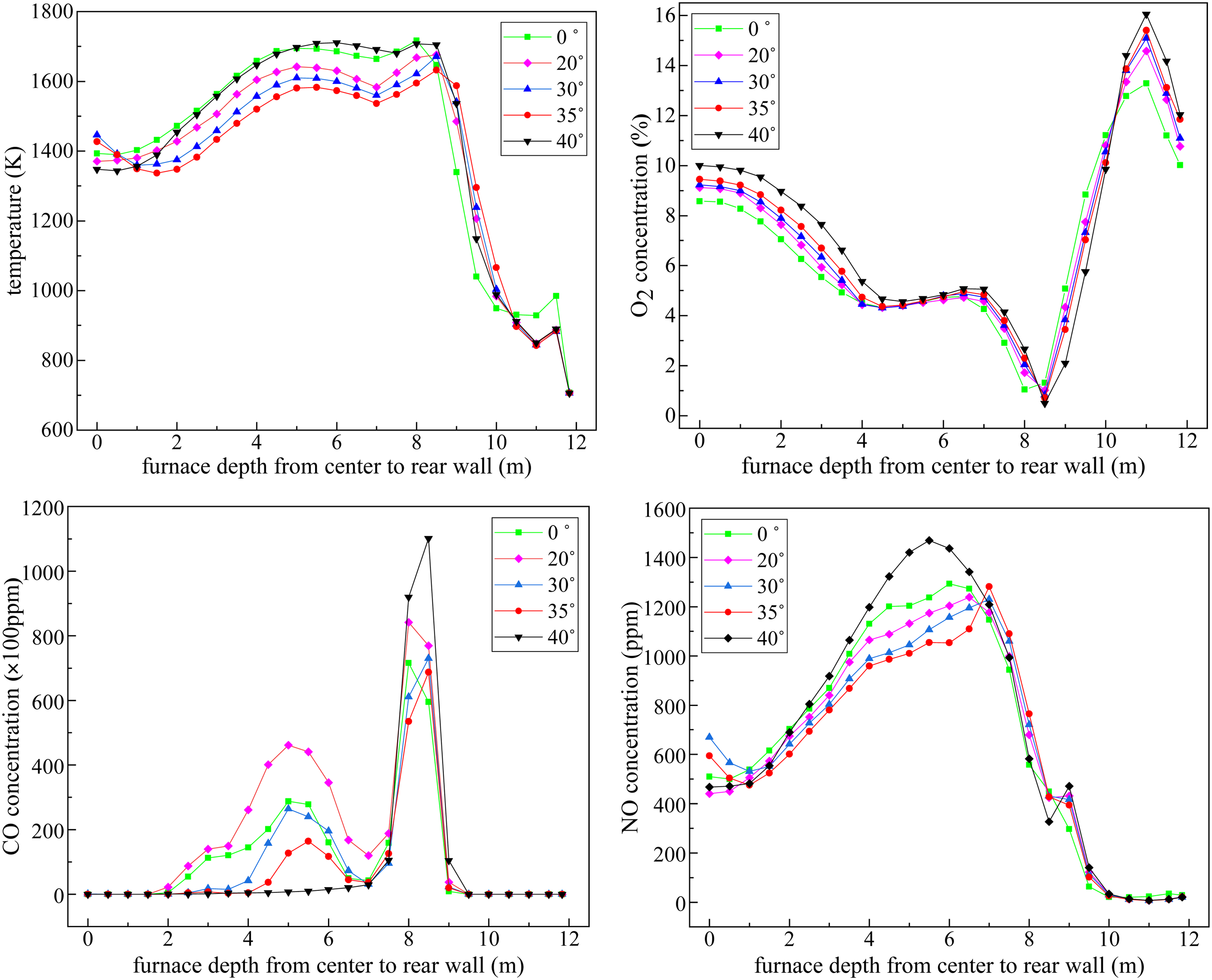
SAF's representative data distribution patterns along the horizontal line B.
Figure 7 also shows that with enlarging θ, both temperature and NO content present an rise-to-drop pattern in the right-half part while reverse the pattern in the left-half part. O2 initially presents a rise behavior in the narrow near-wall zone but then decreases continuously for a wide line span. CO initially increases in the first surged stage near the rear wall and subsequently shows a rise-to-drop behavior in the much shallower CO-increase stage near the furnace centerline. These trends with θ are explained by several aspects: (i) As mentioned previously (Figure 3(b)–(e)), because the overall in-furnace combustion first strengthens and subsequently degrades with θ, a strengthened combustion pattern lengthens its flame penetration to respectively rise and drop combustion fragments occurring in the hopper and in the upward flame. Therefore, a combustion pattern characterized by a relatively poorer or weakened state should yield opposite results. In general, an increase in combustion share is associated with higher levels of CO and gas temperature, along with a decrease in residual O2. (ii) Aside from the mentioned behavior of lengthening the flame penetration depth, increasing θ not only allows more air to blow the narrow near-wall zone but also postpones the char combustion aided by the UHA, thereby raising O2 in the near-wall zone while generating an opposite trend in the adjacent intense combustion zone; and (iii) In a relatively poorer or weakened combustion pattern such as the ones at θ = 0° and 40°, the relatively higher char combustion share occurs in a high-temperature (∼1700 K) and sufficient-oxygen (∼5%) atmosphere in the central zone, finally achieving high NO levels. A comprehensive consideration of a lower char combustion share for the final burnout and lower NO production along the Line B, suggests that the optimal UHA angle should be set at 35° in this work.
SAF's final performance indexes
Table 1 provides the final indexes of the SAF. As the UHA angle increases, almost all of the CO and NO emissions, combustible matter in fly ash, and residual oxygen descend first and then ascend, with the exception of a small increase in CO emission and residual oxygen at θ = 35°. This trend occurs mainly because as θ increases, the overall in-furnace combustion first strengthens and subsequently degrades and meanwhile, the NO production shows an opposite decrease-to-increase trend (Figure 3(b)–(e)). A detailed explanation is as follows. In the SAF furnace with the staged hopper-air pattern, when using an inclined UHA angle to lengthen the downward flame travel, the large circular special zones with the preceding and primary combustion stages entrained are enlarged to (i) complete well the major combustion share and (ii) form a local O2-lean environment to inhibit the NO formation. Moreover, the hopper experiences an increase in char combustion fragments due to the extended flame penetration, resulting in fewer unburnt char particles entering the upper furnace. All these circumstances favor a well burnout performance. In addition to NO-inhibition aspect out of the preceding and primary combustion stages, the postponed mixing of the inclined UHA with the downward flame, on the one side, extends the local reductive atmosphere of the reburning zone to strengthen the NO reduction via reburning, on the other side, restrains the char combustion intensity in the downstream. The moderately elevated temperature environment established in both the hopper and upper furnace is not conducive to thermal-NO formation, even in the presence of locally heightened O2 levels in these two zones. The above explanatory materials have clarified why an inclined UHA angle generates such a positive function in improving combustion and meanwhile lowering NO x emissions.
The initially reinforced but subsequently weakened low-NO x combustion with θ ultimately attains the optimal low-NO x performance at θ = 35°, resulting in NO x at about 600 mg/m3 (O2 = 6%) and 5% combustible matter in fly ash. The NO x calculation error (Table 1) adjusts the actual NO x levels of the SAF to 575 mg/m3 (O2 = 6%), indicating significantly reduced NO x emission along with a satisfactory burnout rate. In a related dep-air-staging art without such a staged hopper-air pattern and the UHA declination, 17 the obtained performance indexes with NO x emission at 667 mg/m3 (O2 = 6%) and combustible matter of 5.31% in fly ash are poorer than the present achievement, which also affirms the superiority of this staged hopper-air pattern with the inclined UHA. Compared with the original furnace, 8 the SAF significantly reduces further NO x emissions by about 300 mg/m3 (O2 = 6%) and meanwhile drops again the combustible matter in fly ash, equivalent to a 33.5% NO x reduction plus burnout improvement. Moreover, the previous hopper-temperature comparison (Figures 2(d) and 3(b)) has uncovered that the SAF sharply drops the hopper temperature levels by about 400 K, undoubtedly presenting its technique superiority in resolving the aforementioned hopper overheating problem of the original furnace. 8 An explanation of this low-NO x combustion promotion with the SAF is summarized below. Aside from the conventional low-NO x combustion solutions of air staging and fuel lean/rich bias combustion as used in the original furnace, the SAF not only implements other low-NO x arts of fuel reburning and FGR, but also improves air staging by strategically positioning staged hopper-air jets and reducing air delivery through the upper arches. In consequence, the NO formation is greatly inhibited in the upper-arch zone and meanwhile, NO generated in the upstream is effectively reduced via the fine pulverized-coal reburning. Moreover, as mentioned previously, because of the inclined UHA postponing its mixing behavior with the downward flame, two additional NO-inhibition functions occur, i.e., (i) prolonging the local reductive atmosphere in the reburning zone to enhance NO reduction, and (ii) restraining the char combustion intensity in the hopper to inhibit thermal-NO. These are all the NO-inhibition contributions of the SAF compared with the original art. The enhancement in burnout promotion, albeit to a slight extent, can be attributed to the combined advantages of the SAF, including: (i) A reduced yet more efficient flame penetration depth, (ii) improved air utilization via the staged hopper-air form to favor the local char combustion, (iii) the stronger recirculating gas below upper arches, and (iv) extended spread of OFA in the burnout zone.
According to the above performance merits, the SAF has apparent advantages in reducing sharply NO x emissions, achieving high burnout, and lowering apparently hopper temperature levels to eliminate the hopper overheating as compared with other low-NO x technologies7–10,16 fit for arch-fired furnaces. Meanwhile, the SAF can also incur shortcomings in cost and ease of implementation (such as the complexity in structure and operation adjustment). In detail, this SAF furnace with the staged HA increases the complexity of the air/fuel supply system, boiler's manufacturing cost, and difficulty of the timely air adjustment according to combustion status. However, in this work the SAF with the staged HA has presented prominent roles in improving the in-furnace combustion and final performance merits, which include (i) deepening air staging, (ii) shortening the downward flame penetration, and (iii) strengthening the UHA's combustion-aided role for burnout while remaining the LHA's hopper-protected function. As a result, NO x production is clearly reduced, combustion efficiency is improved, and the hopper overheating is removed. On the increasingly strict pollutant emission limits, the SAF equipped with the staged HA is still necessary to an advanced arch-fired furnace characterized as further lower NO x emissions, high burnout, and safe operation without such a hopper-overheating problem.
Conclusion
In the 600-MWe arch-fired furnace exhibiting persistently high NO
x
emissions and a notable risk of thermal fatigue in the hopper, a comprehensive investigation was conducted through real-furnace tests and simulations. The original low-NO
x
approach was replaced with the SAF owning a staged and inclined hopper-air pattern. Simulations were conducted at different UHA angles to explore the impact of UHA angles and assess the effectiveness of SAF in improving low-NO
x
performance and mitigating the thermal fatigue issue of the hopper. Key conclusions are outlined below.
The original furnace, characterized by an excessively deep flame penetration and numerous high-temperature zones, resulted in persistently high NO
x
emissions, particularly in the lower furnace, and posed a significant risk of thermal fatigue in the hopper. In contrast, the SAF achieved a shallower but more efficient downward flame penetration, improved hopper-air utilization for char combustion, significantly lower hopper gas temperatures, and enhanced OFA penetration in the burnout zone. The SAF effectively suppressed both fuel-NO and thermal-NO, with the primary NO formation relying on thermal-NO in the primary-combustion zone. This differs from conventional air-staging arch-fired furnaces where fuel-NO remains dominant. Varying the UHA angle (θ) in the SAF initially strengthened and then weakened combustion, leading to a drop-to-rise change in NO and CO emissions. Among the different angles tested, θ = 35° emerged as the optimal configuration, achieving NO
x
levels of 600 mg/m3 (O2 = 6%) and combustible matter of 5% in fly ash among the five angle setups. Reasonably inclining the UHA not only increased downward flame penetration but also enhanced fuel reburning, inhibiting NO formation and thermal-NO in the downstream. This resulted in improved combustion and reduced NO
x
emissions. Compared to the original furnace, the SAF furnace with the optimal θ = 35° demonstrated a further reduction of approximately 300 mg/m3 in NO
x
(O2 = 6%) while concurrently lowering burnout loss. This equates to a 33.5% reduction in NO
x
emissions alongside enhanced burnout. The confirmed efficacy of SAF in improving low-NO
x
combustion and reducing hopper temperatures highlights its potential for practical application.
Footnotes
Declaration of conflicting interests
The authors declared no potential conflicts of interest with respect to the research, authorship, and/or publication of this article.
Ethical approval
Funding
The authors disclosed receipt of the following financial support for the research, authorship, and/or publication of this article: This work was supported by the National Natural Science Foundation of China, Natural Science Foundation of Ningbo (grant number 52276122, 2022J113).