
Abstract
Within a 600 MWe staged arch-firing furnace (SAF) having the staged hopper air (HA) and overfire air (OFA) as its last two air-staging layers, the present attention was focused on evaluating the impact of the HA:OFA distribution and determining an appropriate HA:OFA ratio used to improve the hopper environment and low-NO x performance. Accordingly, by varying the HA:OFA distribution at a total air ratio of 31%, four HA:OFA ratio settings of 11:20, 13.5:17.5, 16:15, and 18.5:12.5 were formed to compare the in-furnace flow, coal combustion, and NO x emissions. With increasing the HA flux to raise the HA:OFA ratio, all of combustion symmetry, the downward flame penetration, and the HA's combustion-aided effect on char firstly improved and then weakened, the OFA penetration became shallower, and the high-temperature flame in the upper furnace extended. Final performance indexes showed that both NO x emissions and burnout loss first declined and then ascended, meaning a rise-to-drop trend in the low-NO x performance as deepening the HA:OFA ratio. Among the four settings, the moderate HA:OFA = 13.5:17.5 achieved the optimal indexes with NO x emission of 543 mg/m3 (6% O2) and carbon in fly ash of 4.89%. Compared with its previous reference furnace (holding levels of 905 mg/m3 and 5.1% respectively in the two index aspects), the SAF furnace using such a HA:OFA distribution mode reduced significantly NO x by 40%, improved a little burnout, and dropped apparently the hopper temperatures by 500 K to eliminate its high overheating risk.
Introduction
At present, because of environmental protection and sustainable development as a global issue, how to properly deal with the environmental pollution caused by industrial coal-fired furnaces has become a research hotspot.1,2 Among various types of coal-fired furnaces, arch-firing furnaces designed to burn low-volatile coals are widely used in China due to their special combustion organization principles.3,4 However, due to the requirements of stringent combustion conditions and poor reactivity of these coals, 5 actual operations often present problems of low burnout, strong slagging, and high NO x emissions. This raises a hard-to-resolved challenge in the energy and environment field for a high-efficiency utilization of these fuels.6,7 In order to improve combustion and reduce NO x emissions, great efforts have been devoted to the research on arch-firing furnaces. By introducing overfire air (OFA) to deepen air staging in a 300 MWe furnace, Li et al. 8 reduced NO x emission by 50% while affecting a little burnout. Ma et al. 9 proposed a staged wall-air box pattern for a 300 MWe furnace and found that it reduced carbon in fly ash from 8.85 to 5.93% and dropped NO x emissions from 1241 to 984 mg/m3 at 6% O2 (fixing this O2 benchmark for NO x emissions in the next). In order to reduce NO x emissions and eliminate the upper furnace's serious slagging (due to the vent-to-OFA arrangement), Liu et al. 10 proposed a low-NO x combustion solution for a 300 MWe FW arch-firing furnace by channeling vent air through the E-layer secondary air, inclining and reconstructing the F-layer secondary air, and removing the D-layer secondary air, whose simulated results revealed that NO x emissions were reduced by 36% while carbon in fly ash increased apparently. Kuang et al. 11 designed a multiple air-staging combustion technology and ultimately achieved a low-NO x combustion merit with NO x emissions of about 870 mg/m3 plus combustible content above 5% in fly ash. With the attention focused on the fuel rich/lean ratio, Wang et al. 12 increased the primary-air velocity by decreasing the vent-air damper opening, which optimized the combustion process, significantly improved burnout, and reduced NO x emissions. Aiming at creating a high-burnout and low-NO x environment, Zhang et al. 13 strengthened primary air and separated the secondary-air arrangement to lengthen the downward flame penetration, while this solution also yielded a hopper's overheating risk because of the excessive flame penetration. By adding the arch-supplied secondary air near the front/rear walls used to strengthen air staging, prolong the downward flame penetration, and expand the recirculation zones below furnace arches, Wang et al. 14 found that the industrial application of this low-NO x solution could reduce NO x emissions by over 33% in a 660 MWe furnace. A sidewall-dominated, W-shaped flame combustion pattern from Kuang's group, 15 which was developed for resolving problems of the severely asymmetric combustion, particularly poor burnout, and high NO x emissions in a 600 MWe furnace, was numerically confirmed to achieve an excellent furnace performance featured by symmetrical combustion and sharp reduction rates in both NO x emissions and carbon in fly ash. For lowering further NO x emissions and relieving the hopper's overheating problem caused by the excessive flame penetration in a 600 MWe furnace, a staged arch-firing framework with a primary-burner flue gas recirculation (FGR) was developed by Cheng et al., 16 whose numerical results demonstrated a NO x reduction rate of 33% and a hopper's temperature decrease of 400 K.
Obviously, the above studies have gained many valuable results in improving the low-NO x combustion within arch-firing furnaces. However, for reducing the flue-gas denitration cost as much as possible, there still exists an incompatibility between much lower in-furnace NO x levels and high burnout (such as creating circumstances of NO x below 600 mg/m3 plus carbon in fly ash below 5%). Meanwhile, other incurred problems (such as the hopper's overheating environment5,11,17,18) as deepening air staging and lengthening the flame travel, should be deserved equal attention for establishing furnaces’ safe operations. To address the above shortcomings and purse lower NO x merits as facing the increasingly stringent emission limits, a staged arch-firing low-NO x framework (abbreviated as the staged arch-firing furnace (SAF) in the next) was developed in the published work.16,18,19 Considering (i) the mentioned hopper's overheating environment due to the excessive flame penetration 18 and (ii) the shallow arch-delivered OFA penetration in the furnace throat (due to the head-on collision of OFA with the recirculating gas beneath the arch), 16 two solutions were applied in the SAF. First, a staged hopper air (HA) form was used to not only enhance further air staging but also protect the hopper wall. 19 Second, a throat-OFA form was applied to extend the OFA penetration by avoiding such collision. According to the combustion configuration, the SAF owns a comprehensive deep-air-staging framework with secondary air and staged air as the former two air-staging layers in the upstream while HA and OFA as the latter two air-staging layers in the downstream, respectively. HA aides char combustion in the downstream of the reburning zone, whereas OFA completes final burnout in the upper furnace. Obviously, the air distribution between HA and OFA, as an important determinant factor, should impact apparently the low-NO x combustion and hopper environment. Specifically, for a fixed total flux of HA and OFA, a moderate HA flux may enhance the local char combustion and the hopper-protected behavior while remain sufficient OFA for burnout in the upper furnace. On the contrary, an excessive HA injection may incur dual negative impacts. On one hand, the excessive HA dilutes the reductive atmosphere to weaken the NO-reduction function of fuel reburning and simultaneously declines its utilization for char combustion, on the other hand, the resulted insufficient OFA worsens the final burnout in the upper furnace. However, up to now, a comprehensive investigation on the staged HA and its air distribution between OFA in the downstream is absent in the published literature. This academic gap and the aforementioned requirements of the HA:OFA distribution for improving the SAF's low-NO x combustion performance thus incur the present work. That is, in order to evaluate the HA:OFA distribution impact on the SAF's low-NO x combustion and hopper environment and then establish rationally an HA:OFA distribution mode, the present study is devoted to comparing the in-furnace flow, coal combustion, NO x emissions, and hopper environment at various HA:OFA distribution setups within a 600 MWe SAF furnace modified from a previous deep-air-staging furnace in.11,18 The findings can offer a useful guidance on how to effectively and safely regulate ultra-low NO x combustion within arch-firing furnaces.
The 600 MWe SAF furnace and methods
Information about the SAF furnace and its case setups
The SAF furnace is a modified version on the basis of the previous deep-air-staging furnace11,18 (i.e., labeled as the reference furnace below). Compared with the reference furnace, the SAF furnace remains the main furnace body unchanged while has modifications in three aspects. First, the SAF reconstructs the furnace arches into a distinctive staged upper/lower arch pattern. In detail, the upper arch is used to arrange primary burners, which convey secondary air and the fuel-rich coal/air flow to regulate the primary combustion. The lower arch is designed to set auxiliary burners, which deliverer the fuel-lean coal/gas flow into the reburning stage. Second, the SAF enriches the low-NO x combustion framework. Aside from deepening again air staging, FGR and fine pulverized-coal reburning are added in the SAF. A combination of FGR and fine pulverized-coal through auxiliary burners essentially strengthens the reductive atmosphere in the reburning process. The ratios of FGR and fuel reburning are designed at 20% and 15%, respectively. With the pulverized-coal fineness following the Rosin-Rammler algorithm, the pulverized-coal particles in the primary burners for combustion have a median diameter of 55 μm, while those in the auxiliary burners for reburning own an apparently lower median diameter of 15 μm. Third, the SAF comprehensively deepens again air-staging conditions. Along the U-shaped flame trajectory, the flux-declined secondary air, location-elevated staged air, HA in a staged form, and OFA are supplied in turn to enhance apparently the air-staging conditions. The staged HA consists of the upper HA (UHA) at the uppermost edge of the hopper and the lower HA (LHA) in the hopper's upper zone, where the UHA's declinate angle is set at 35° and the LHA is horizontal, respectively. According to the combustion organization, the declinate UHA mainly favors the char combustion below the reburning zone. An excessive UHA flux may affect the reductive environment in the lower part of the reburning zone. The horizontal LHA is designed to end the downward flame penetration and protect the hopper wall. OFA is responsible for completing the final combustion in the upper furnace. Figure 1 and Table 1 respectively offer a schematic diagram of the SAF furnace and its air/coal parameters.
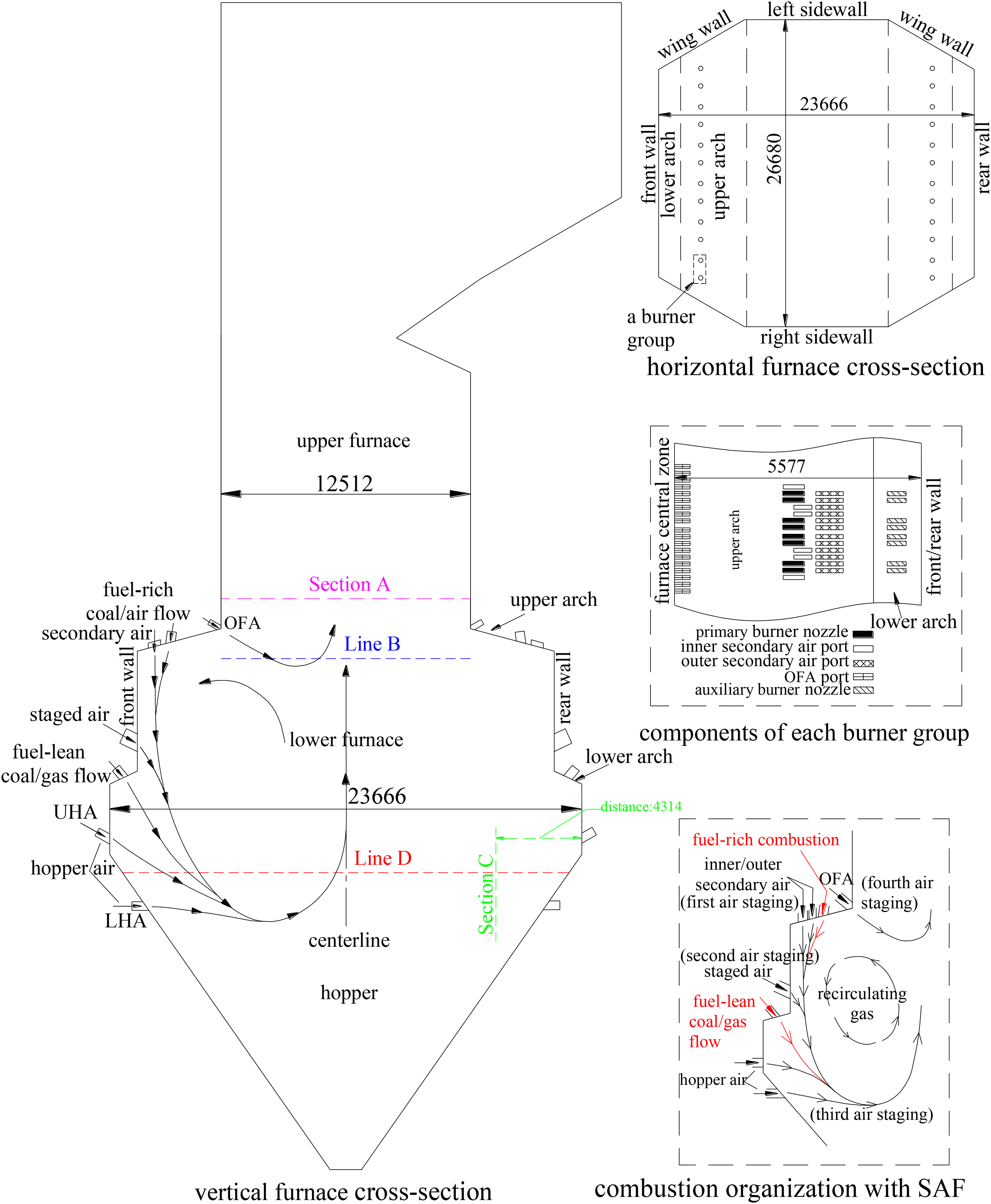
The 600-MWe staged arch-firing furnace.
Parameters in the 600-MWe arch-firing furnace before and after the SAF.
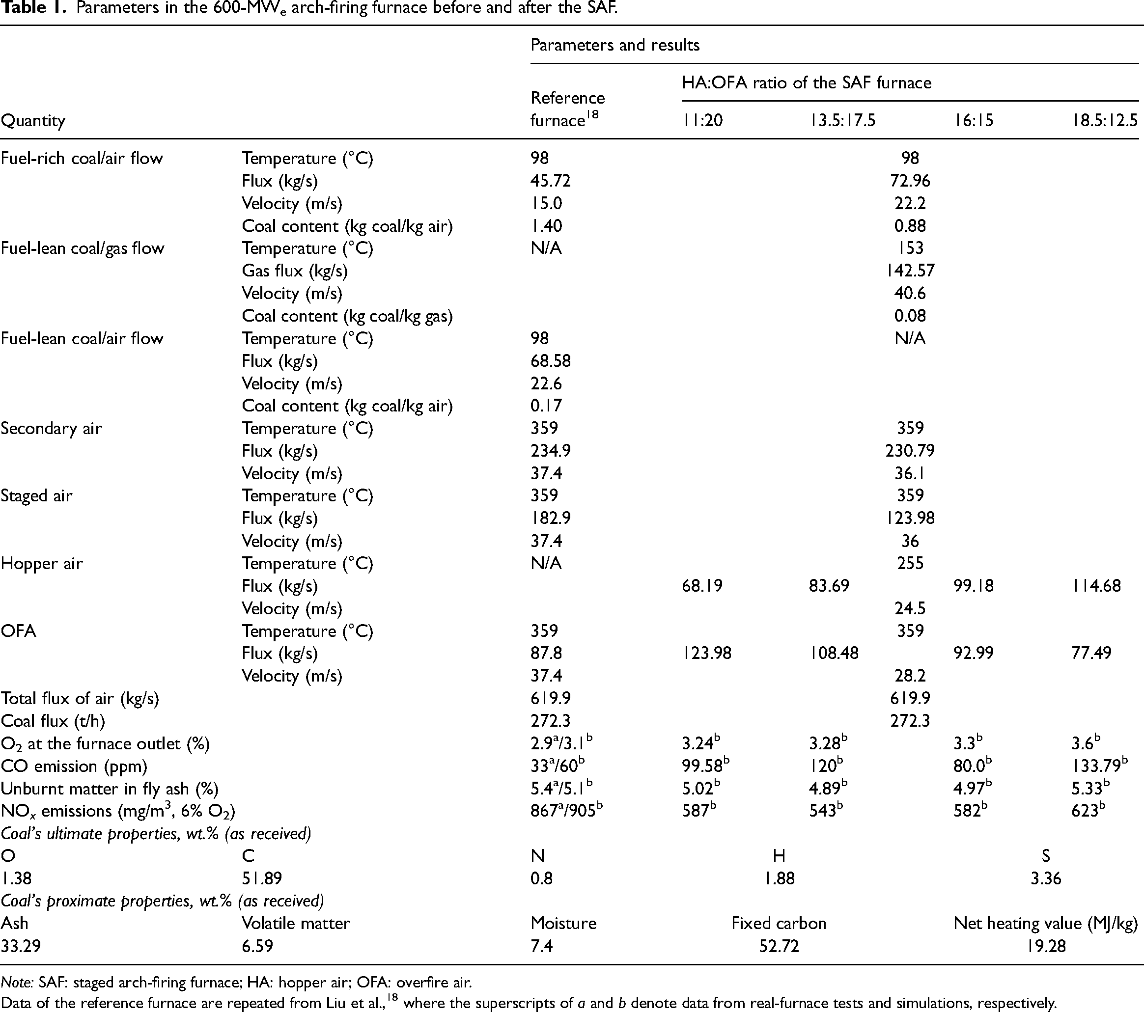
Note: SAF: staged arch-firing furnace; HA: hopper air; OFA: overfire air.
Data of the reference furnace are repeated from Liu et al., 18 where the superscripts of a and b denote data from real-furnace tests and simulations, respectively.
According to the aforementioned information, the air distribution between HA and OFA is very likely to affect the low-NO x combustion characteristics, hopper environment, and final furnace-performance merits. Based on a combination of (i) the reburning application raising the combustion share in the downstream, (ii) the functions of the UHA and LHA, (iii) the conventional OFA parameters8,11,12,17 for arch-firing furnaces, and (iv) our previous investigations respectively on the HA 19 and OFA, 20 the key external conditions as varying the HA:OFA distribution in this work were fixed at a total HA and OFA ratio of 31% and a UHA:LHA ratio of 6:4. Accordingly, four HA:OFA ratio setups of 11:20, 13.5:17.5, 16:15, and 18.5:12.5 were regulated. Table 1 lists the jet parameters of the four SAF settings as well as those of the reference furnace. Following the industrial-scale flue gas parameters of the reference furnace, here the gas components of FGR were set at N2 = 75.55%, CO2 = 13.1%, H2O = 5.69%, O2 = 5.25%, SO2 = 3300 ppm, NO = 380 ppm, and CO = 338 ppm.
Simulation setups and the related verification
Considering the symmetrical furnace and the combustion-independence between each burner group, a half of the furnace body in the furnace breadth was selected as the computation domain. Figure 2 shows the computational area of the SAF furnace and its grid division. To ensure accuracy regardless of the grid density used, representative grid-independent tests were conducted prior to the final simulations. The form was using the calculated longitudinal-velocity distribution of Vy at a fixed furnace height of H = 24 m. In Figure 2, it can be seen that at various grid densities of 3.55, 3.025, 2.2, and 2.005 million, Vy presents a similar distribution pattern and varies slightly with the tested grid numbers. Consequently, the minimal mesh setup of 2.005 million was selected for saving the simulation efforts while remaining the accuracy. The software of Fluent was used to carry out numerical calculations and the selected calculation models are described as follows. Since the airflow in pulverized-coal furnaces is usually complex, nonstationary, multiphase, turbulent, and nonuniform, the realizable k–ε model was selected for the gas-phase turbulence simulation. This turbulence model is more accurate in expressing the physical characteristics of complex turbulence, and has better applicability especially in the complex cases such as flow rotation and curved flow. In view of the furnace radiation accounting for more than 95% of total heat transfer in pulverized-coal furnaces, the P1 radiation model was taken for modeling heat transfer. This heat-transfer model can better capture the basic features of radiative heat transfer in the combustion region of pulverized-coal furnaces, having a high computational efficiency while guaranteeing the calculation accuracy. Considering that the combustion process of pulverized-coal particles is actually a kind of turbulent gas/solid two-phase flow motion, the Lagrangian stochastic orbital model was chosen for modeling the pulverized-coal motion process. Upon taking into account the random perturbation of particles in the turbulent environment, this Lagrangian model can reflect the motion state of particles more realistically, and shows good applicability for the complex scenarios like pulverized-coal furnaces. For the complex coal pyrolysis combustion process, the two-course competitive model and the probability density function (PDF) method of the nonpremixed combustion model were chosen for the volatile precipitation and combustion processes, respectively. In particular, with considering the non-uniformity and incomplete mixing between devolatilization and combustion, the PDF model simulates the complex combustion processes more accurately. The two-course competitive model considers different reaction situations at high and low temperatures and is thus more accurate. The char undergoes nonhomogeneous combustion in a gas-phase oxidizer and a process governed by both chemical kinetics and diffusion, yielding a section of the power-diffusion control model for char combustion. This char-combustion model not only considers the chemical reactions and oxygen transport processes on the surface of the particles, but also allows for a more accurate prediction of the combustion rate and the generation of combustion products. In pulverized-coal furnaces, it is conventionally thought that the influence of NO x on the mixing and thermodynamic characteristics of the gas-phase substances is slight. In order to simplify the calculation, a postprocessing approach was thus used to calculate the NO x generation. Given that NO occupies more than 95% of NO x in pulverized-coal furnaces, only NO generation was considered in the present simulations. The calculation of thermal-NO and fuel-NO was respectively based on the Zeldovich mechanism and De Soete model, while fast-NO was ignored because it accounted for an extremely small share in the total NO generation. This NO-calculated approach could ensure that the accurate flow, heat transfer, and combustion simulation results were obtained and NO production was precisely analyzed. Regarding the setting of boundary conditions, the present simulations applied the no-slip wall boundary conditions, where a wall-function method was used to calculate the near-wall fluid and wall temperatures were fixed at 700 K throughout the furnace. The above models and methods are conventional for simulations on pulverized-coal furnaces and details can be found in the literature.21,22
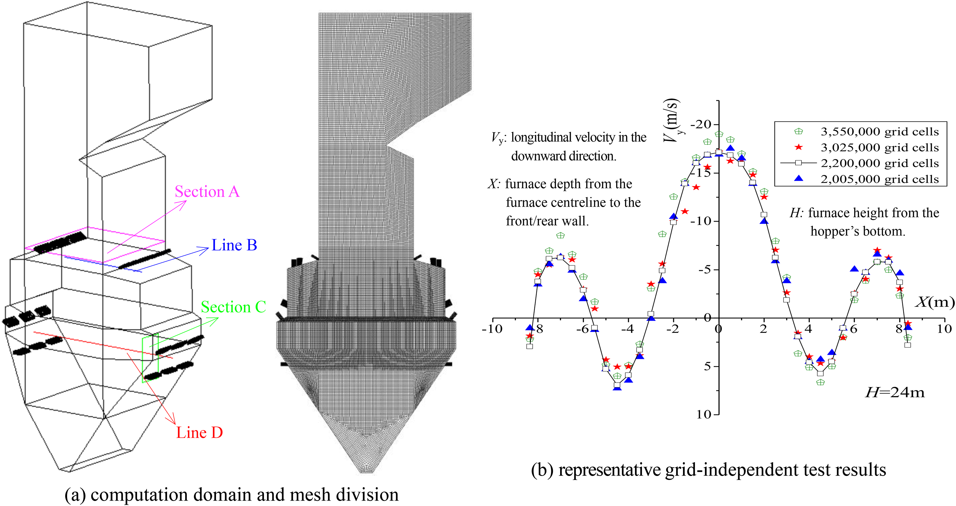
The computation domain, selected lines and sections for data extraction, mesh-partition pattern, and representative grid-independent test results.
With respect to the simulation verification, the published literature18,20 compared comprehensively the data of real-furnace measurements and simulations (using the same methods and models as described above) within the reference furnace. It was reported18,20 that for both the in-furnace data (including distributions of gas temperature and species content) and the furnace-performance indicators (CO and NO x emissions, residual oxygen, and carbon in fly ash), the tested and simulated versions were well consistent all the time, showing low calculation errors generally less than 5%. These reported results had confirmed the simulation validation. In view of (i) the mentioned high furnace similarities (i.e., sharing the same furnace dimensions but with only the combustion system retrofitted to a SAF version) and (ii) the same simulation methodology used for both two furnaces, it is thought that the previously verified simulation methodology via the reference furnace is reliable to simulate the SAF furnace.
Results and discussion
Flow-field distribution within the SAF furnace as varying the HA:OFA ratio
Flow fields at the four HA:OFA ratios are given out in Figure 3. In terms of the W-shaped flow field formation, the fuel-rich flow is first directed downward by the two ties of secondary air and then mixes in turn with the staged air, fuel-lean coal/gas flow, and HA before reversing in the hopper's upper zone. The descent-to-ascent flow trajectory thus regulates a U-shaped flame pattern in each half part of the furnace. This U-shaped flame travel plus the velocity difference between the high-speed arch-supplied jets and the low-speed upward gas, develops a pair of strong recirculation zones below the upper arches. In the throat zone, the declinate OFA penetrates to mix with the upward gas before reversing upward. Also based on this U-shaped flame form and the velocity-difference mechanism, Wang et al. 14 added the arch-supplied secondary air in the zone near the front/rear walls to lengthen the flame penetration and strengthen the recirculation zones, which was confirmed to be effective in improving combustion and reducing NO x emission. According to the literature,16,18,20 the reference furnace's flow field mainly holds two-fold shortcomings: (i) the downward flow penetrates excessively into the hopper's lower part, because of a high downward rigidity involving secondary air and the fuel-lean coal/air flow (Table 1); and (ii) OFA diffuses poor in the furnace throat zone, because of the arch-delivered OFA facing a head-on collision behavior with the strong recirculating gas below the arch. A comprehensive flow-field comparison suggests that applying the SAF in the reference furnace resolves well the two-fold shortcomings. First, due to an effective downward rigidity decrease (i.e., decreasing secondary air and removing the fuel-lean coal/air flow, Table 1) and the strengthened interception in turn by the location-elevated staged air and LHA, the downward flow ends reasonably in the hopper's upper zone. Second, the new throat-OFA form not only lengthens its OFA spread in the burnout zone but also avoids a head-on collision with the strong recirculating gas toward the burner outlets. In comparison to the above solutions in this work (i.e., reducing the arch-air flux and strengthening the wall-air interception) for shortening the downward flow penetration depth, investigations of Song et al.17,23,24 into this excessive flow-penetration issue in the same reference furnace 18 were not limited to a reduction in the inner secondary-air flux, but also turned to elongating burner distance and modifying the burner layout.
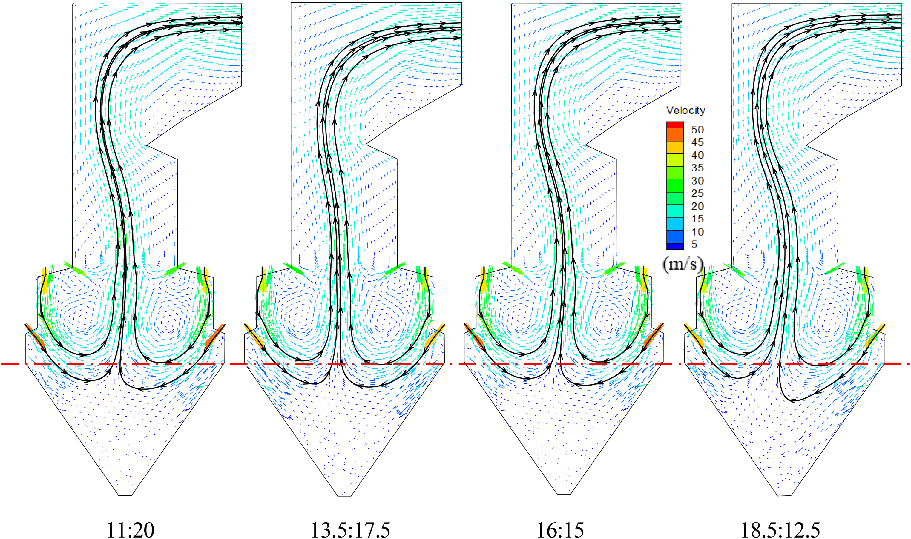
Flow fields at various HA:OFA ratios.
Figure 3 also reveals that, with raising the HA flux to enlarge the HA:OFA ratio, both the flow-field symmetry and downward flow penetration initially ameliorate a little but then deteriorate apparently, while the OFA spread weakens continuously. An explanation is below. With HA far from the upper arch and the downward flow herein having already decayed sharply, its declinate UHA and horizontal LHA respectively direct and reverse the downward flow. The UHA's directing function lengthens the downward penetration, while the LHA's interception facilitates to end the penetration. Meanwhile, either a strong LHA's interception or a powerful OFA penetration behavior can strengthen the internal extrusion 11 between the two upward gas flows stemming from the front/rear half parts, which is a major factor favoring the flow-field asymmetry. With increasing HA and meanwhile decreasing OFA to elevate the HA:OFA ratio, because (i) the dragging behavior of the declinate UHA on the downward flow strengthens and (ii) the mentioned internal extrusion related to the OFA's impulse weakens, the flow-field symmetry improves and the downward flow penetration lengthens. While raising excessively the HA:OFA ratio (such as reaching the ratio level of 18.5:12.5) enables both the declinate UHA and horizontal LHA to own a strong interception on the downward flow. This behavior strengthens the mentioned internal extrusion. Consequently, both the downward flow penetration and flow-field symmetry deteriorate. Among the four settings, requirements of (i) perfecting the flow-field symmetry for symmetrical combustion and (ii) shortening reasonably the downward flow penetration for burnout and the hopper-overheating removal,16,18,20 necessitate a moderate HA:OFA ratio (such as 13.5:17.5) when deepening further air staging in the SAF furnace.
Fields of gas temperature and species content regarding the HA:OFA ratio
Figure 4 presents fields of gas temperature and species content at the four HA:OFA ratios. The four cases show similar distribution characteristics in these data fields and details are described as follows. (i) Characteristics of high O2 and low levels of temperature, NO, and CO distribute in the near-wall region and in the hopper's lower and middle parts. These are explained by a combination of multiple air injections for deepening air staging, the HA arrangement, the wall's heat-absorption behavior, and a small combustion share undertaken in both the hopper and upper furnace; (ii) a pair of oval special zones, which are symmetrically located in the front/real half parts and range from the upper arch to the hopper's upper edge, show characteristics of high temperature, thoroughly low O2, high CO, and medium NO. The special zones basically correspond to the recirculation zones mentioned above, where the high-temperature and low-O2 recirculating gas not only heats the fresh pulverized-coal to promote ignition and stable combustion, but also reduces the local oxygen to inhibit the formation of fuel-NO; (iii) in the narrow central part extending from the hopper's upper edge to the furnace nose, a vertical special zone featuring high temperature and low levels of O2, CO, and NO, is formed because of the main upward gas and its reactions with OFA. As the upward gas ascends in the vertical special zone, all of gas temperature, CO, and NO first raise and then drop, while O2 shows an opposite trend. The reason for these data trends is that char particles react sequentially with the reversed UHA and OFA, where the powerful OFA in the furnace throat zone increases O2 and decreases levels of gas temperature, NO, and CO.
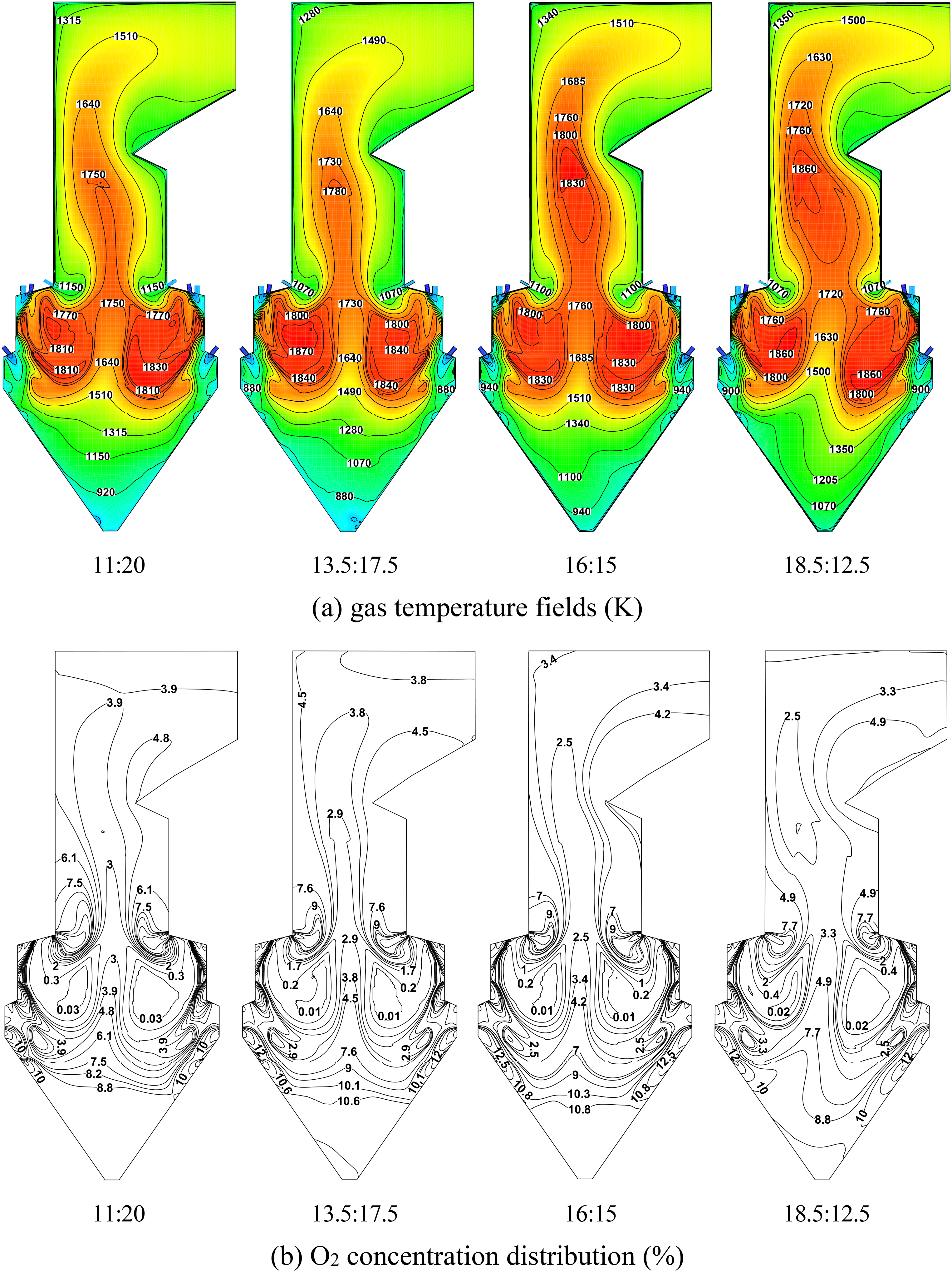
Gas temperature and species concentration fields at various HA:OFA ratios.
A comparison of the above data fields and those of the reference furnace11,18 reveals that the SAF thoroughly improves the in-furnace combustion and hopper environment. The details are below. First, the SAF strengthens combustion intensity, sharply lowers hopper's temperature levels, and raises the oxygen usage for char combustion while remains a sufficient oxidizing atmosphere in the hopper (i.e., from the hopper environment of 1600 K and 17% O2 for the reference furnace16,18,20 to that of 1100 K and 10% O2 for the present SAF furnace). This means that the previous overheating environment and poor air utilization11,18 in the hopper are sharply improved by the SAF application. This occurs because of the reasonably shortened flame penetration and the staged HA application within the SAF. The strengthened combustion intensity is based on the shrunk furnace zone below the upper arch and the stronger recirculating gas below arches. Second, the SAF apparently drops the in-furnace NO levels compared with the reference furnace.16,18,20 This NO-reduction function is mainly based on (i) the SAF's additional low-NO x components of the enhanced air staging, FGR, and reburning and (ii) the reasonable HA:OFA distribution. For the mentioned hopper overheating problem, real-furnace and simulated results from Kuang et al. 11 and Song et al.17,23,24 also emphasized reasons like an excessive flame penetration and poor staged-air usage for combustion.
Figure 4 also shows that regarding the symmetry extent, fields of gas temperature and species content undertake a rise-to-drop trend with the HA:OFA ratio. This is mainly explained by the same flow-field symmetry trend (Figure 3) and the direct relation between flow field and combustion. The overall data trends of these fields are described below. With increasing the HA:OFA ratio, gas temperatures in both the lower furnace and vertical special zone generally raise first and then decrease, while those in the hopper and furnace-outlet zone show a drop-to-rise trend. O2 levels undergo a decrease-to-increase trend in the lower and upper furnaces while present an opposite trend in the hopper. The hopper environment regarding gas temperature and O2 levels thus improves first and then worsens. CO generally declines in the hopper while presents a descent-to-ascent pattern in the lower and upper furnaces. NO presents a rise-to-drop trend in the lower furnace while reverses its trend in the upper furnace. These data trends reveal that with raising the HA:OFA ratio, the combustion status initially improves but then worsens, accompanied by an drop-to-rise NO trend in the furnace-outlet zone. Reasons for the data trends are twofold: (i) The combustion symmetry first improves and then worsens with the HA:OFA ratio. Symmetrical combustion homogenizes the in-furnace gas temperature distribution to decline the thermal-NO formation; and (ii) an initially strengthened but then worsened trend appearing in both combustion status and the downward flame penetration, plus the increased HA while decreased OFA, accounts for the major cause of the above data trends. The continuously increased HA strengthens the hopper-protected atmosphere and lowers its local O2 utilization, while the decreased OFA deteriorates the air-replenished conditions in the furnace throat zone. Due to the weakened combustion in the lower furnace not only raising the combustion fragment in the upper furnace but also elevating the flame kernel location and vice versa, char combustion is thus postponed apparently. The lengthened high-temperature area and the relatively high O2 content thus favor the NO formation. In summary, taking into account the overall combustion status and hopper environment, the HA:OFA ratio of 13.5:17.5 is most appropriate among the four setups.
Local gas temperatures and species levels influenced by HA and OFA
In order to highlight the HA:OFA ratio effect, several sections and lines are selected for extracting the local gas temperatures and species levels. Those include (i) the horizontal Section A and Line B corresponding to OFA and (ii) the vertical Section C and horizontal Line D in the hopper facing HA, as shown in Figures 1 and 2.
Figure 5 illustrates the data distributions on the horizontal Section A with a small distance over the furnace throat. These data distributions represent the local char combustion status at the upper furnace's lower part where OFA reverses. The central part of this section is occupied by a gas atmosphere featuring low O2 and high levels of temperature, CO, and NO, while the two side zones present the opposite characteristics. The reason is that the central part is filled with the upward gas where the entrained char particles react intensely with OFA to release heat, consume sharply O2, and generate NO. The intense char combustion in a high-temperature and low-oxygen environment thus releases relatively higher CO. In contrast, the opposite data characteristics in the two side zones occur because the local atmosphere is out of the dominant upward gas, with only a little combustion fragment hard to consume well the diffused OFA. In conjunction with the wall's heat-absorption impact, characteristics of high O2 and low levels of temperature, NO, and CO thus develop. With raising the HA:OFA ratio, data trends on the Section A are as follows. Gas temperature raises continuously in the side zones while shows a rise-to-drop trend in the central part. O2 first declines and then ascends in the central part while decreases continuously in the side zones. CO shows an opposite data trend as that of O2. NO generally raises first and then declines except the ascend at the 18.5:12.5 setting. Reasons for these data trends with the HA:OFA ratio are fourfold: (i) as mentioned above, the Section A is in the upper furnace's lower part, with only a small distance over the furnace throat. Data on this section almost represent the local combustion status just out of the lower furnace; (ii) the central part of this section is dominated by the strong upward gas where char combustion is intensely aided by OFA, while the two side zones are filled with the mixture of weak gas and some OFA; (iii) raising the HA:OFA ratio not only first strengthens and then worsens combustion in the lower furnace, but also decreases continuously OFA; and (iv) combustion symmetry clearly deteriorates at the highest HA:OFA ratio of 18.5:12.5. This event not only weakens the primary combustion to raise the residual combustion fragment in the upper furnace, but also strengthens the local high-temperature zones to favor the thermal-NO formation.
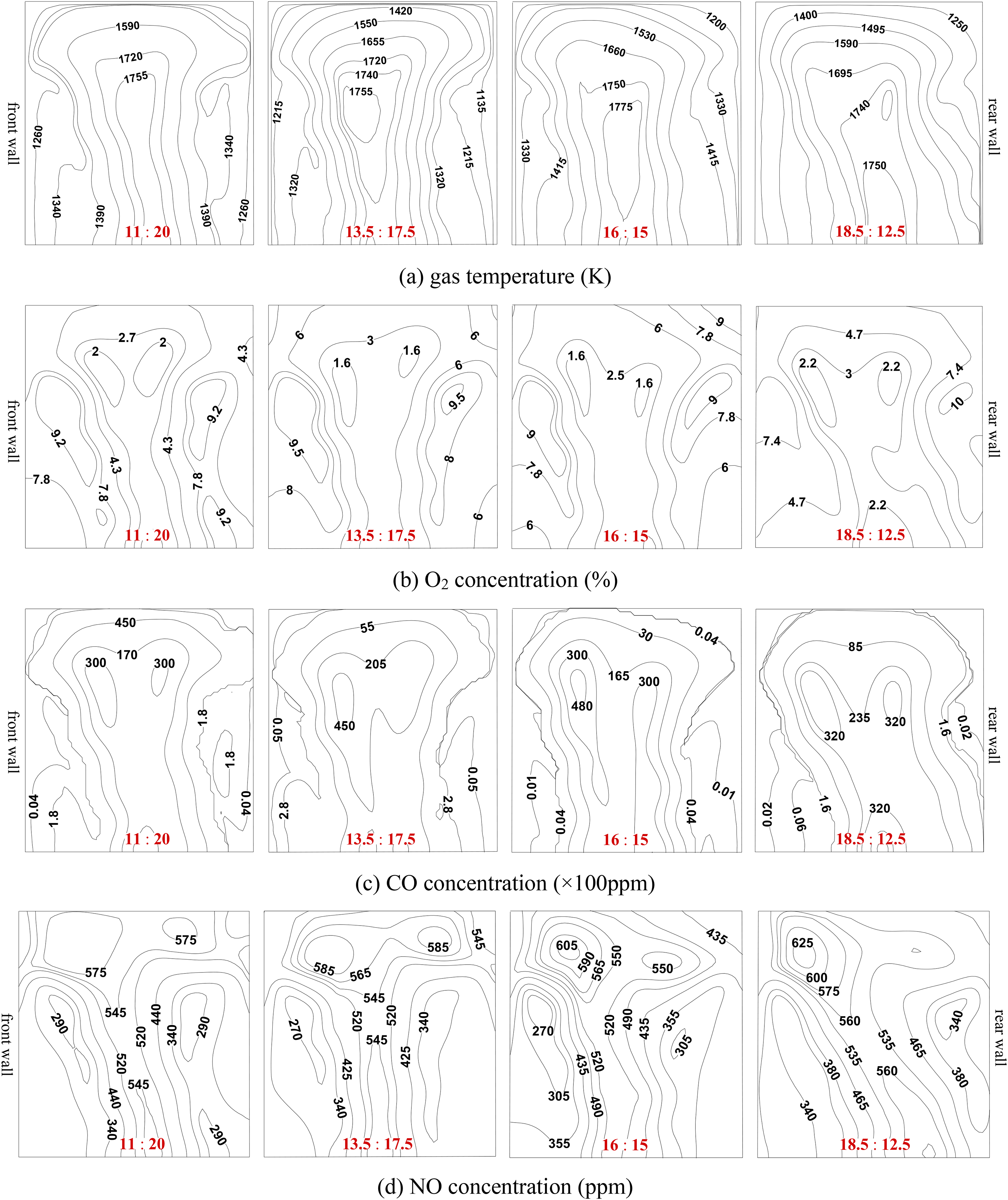
Data distributions on the horizontal Section A over the furnace throat.
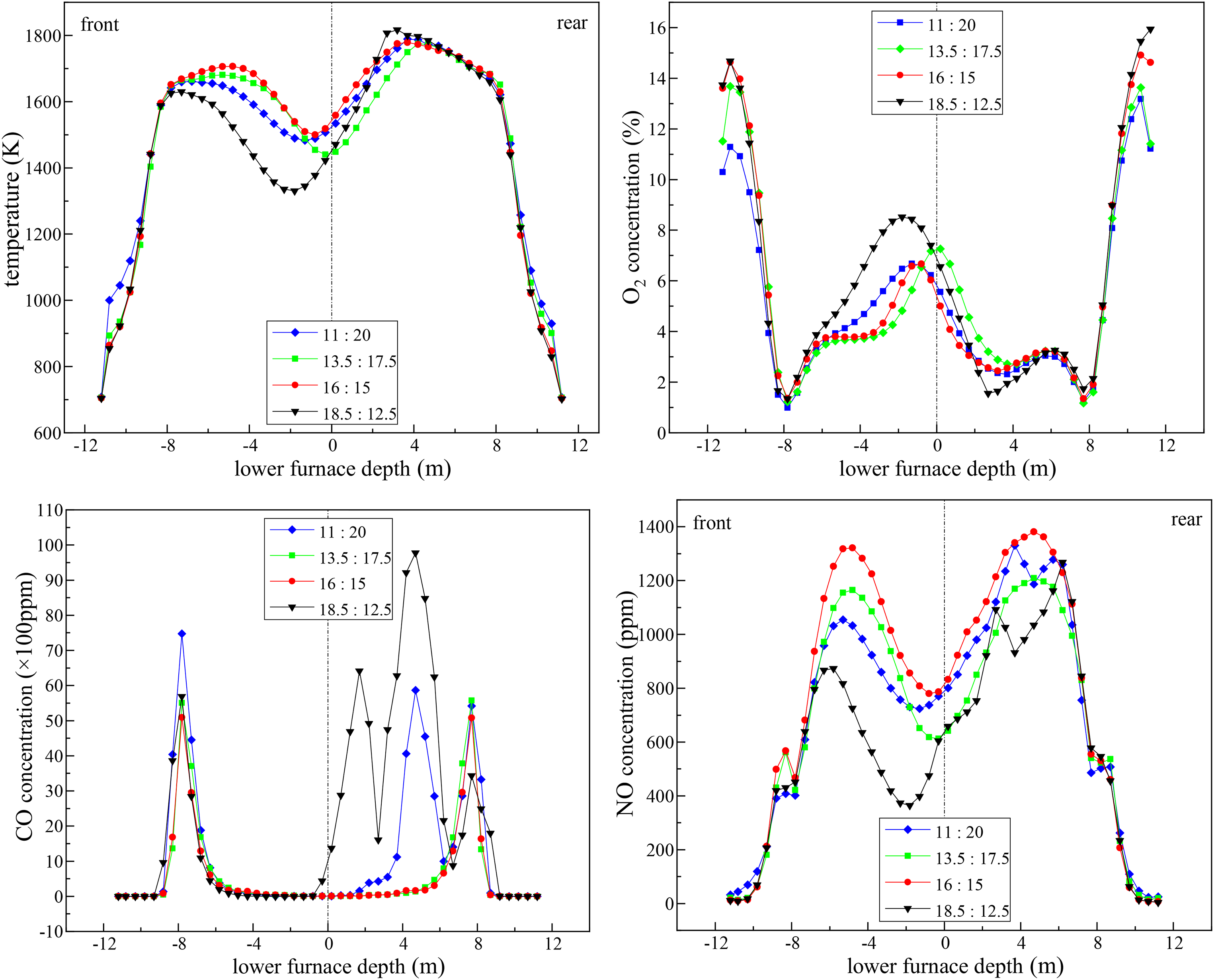
Figure 6 shows the distribution patterns of gas temperature and component concentration along the horizontal Line B. From the front/rear sides to the furnace's centerline, gas temperature first attains a sharp drop-to-rise trend and then maintains at high levels. O2 initially shows an opposite trend as that of gas temperature but then fluctuates at low levels in the central part. CO first varies at low levels and then undergoes a sharp rise-to-drop trend. NO generally decreases first and then increases. These data distribution patterns are mainly attributed to the location of the Line B, which is located at the lower furnace's upmost part with a small distance under the furnace throat. The local combustion status along this line is subject to multiple factors including the recirculating gas, OFA, and upward gas. That is, its two side parts are first affected by the recirculating gas toward the burner zone and then scoured by OFA, while its central part is dominated by the upward gas (Figure 1). The accumulation of the recirculating gas initially develops the characteristics of high temperature and NO but low O2 and CO at two ends of the Line B. Subsequently, OFA first scours the two side parts and then reverses. The initially cooling and diluting impacts but then a powerful combustion-aided role of OFA, thus yield a drop-to-rise trend in gas temperature, NO, and CO while an opposite trend in O2. Finally, because of OFA just reversing at the Line B, the central part of the line is thus dominated by the upward gas almost without OFA diffusion. The transition from the intense combustion (aided by the reversed OFA) to the inert upward gas thus develops the high temperature and NO, low O2, and a sharp CO decrease in the central part. Figure 6 also uncovers the data trends with the HA:OFA ratio. That is, with raising the HA:OFA ratio, both gas temperature and NO generally present a continuous decline in the two ends, a rise-to-drop trend in the side zones, and a drop-to-rise trend in the central part, respectively. O2 generally presents an opposite trend as that of gas temperature. CO shows a rise-to-drop trend in the side zones while reverses its trend in the central part. The above data trends are explained by the fourfold causes of (i) a continuous OFA decrease, (ii) a lower OFA flux weakening the OFA penetration to raise the OFA accumulation in the side zones, (iii) the first strengthened and then worsened combustion in the lower furnace, and (iv) the deteriorated combustion symmetry at the highest 18.5:12.5 setting.
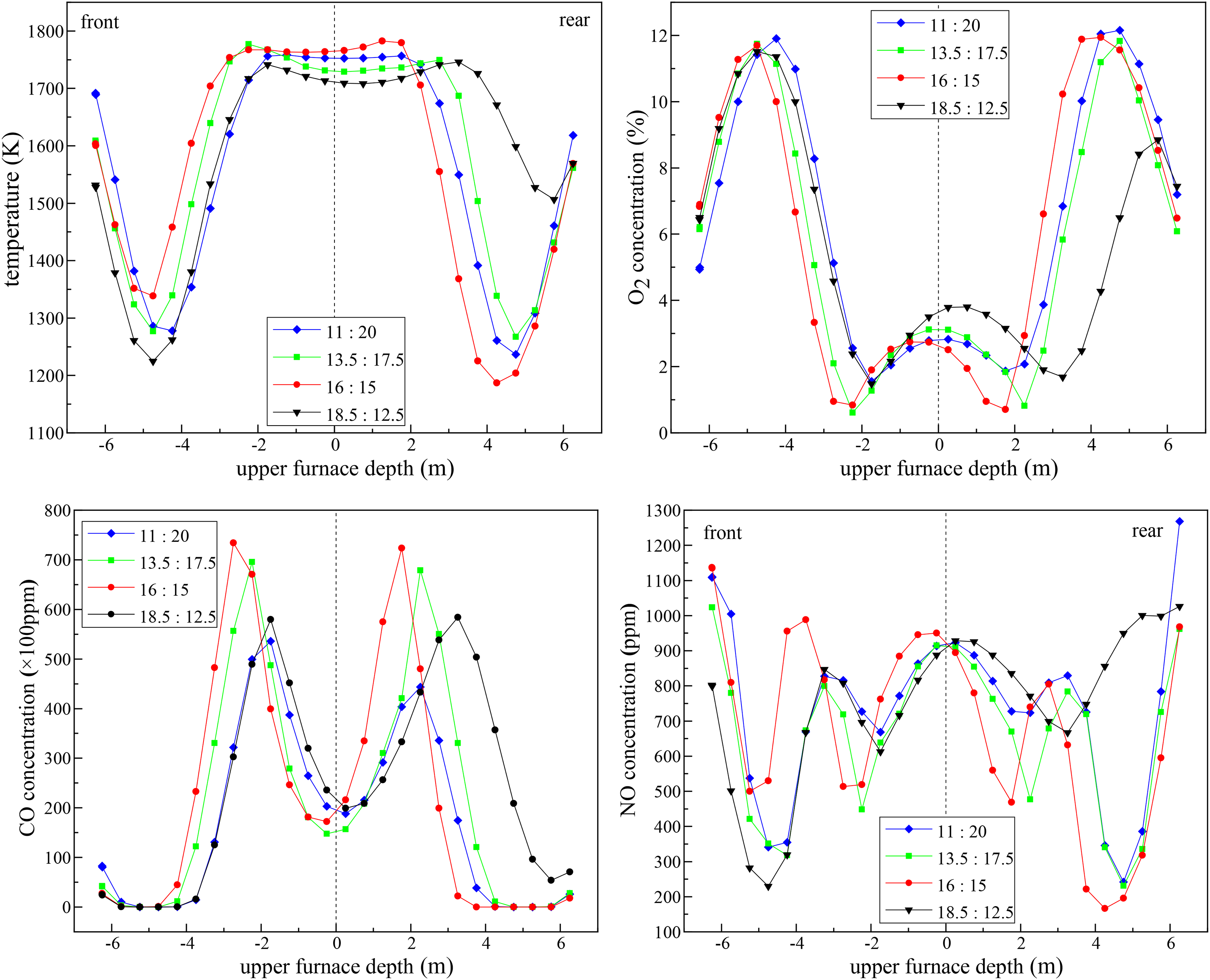
Data curves along the horizontal Line B under the furnace throat.
Based on the above results in Figures 5 and 6, requirements of (i) symmetrical combustion for a better furnace performance and (ii) relatively higher gas temperatures for burnout but lower NO in the throat zone, suggest that the HA:OFA ratio of 13.5:17.5 is more effective to distribute the air between HA and OFA.
Figure 7 displays the data distributions on the vertical Section C, which faces the UHA and LHA with different distances. From top to bottom (i.e., in the flame proceeding direction), gas temperature and NO generally display a rise-to-drop pattern, O2 undergoes an opposite trend as that of gas temperature, and CO declines continuously. These circumstances develop two special zones. The former is a powerful special zone dominating in the upper and middle parts, which features high temperature and NO, low O2, and moderate CO. The latter is a small special zone in the lower part, showing low levels of temperature, CO, and NO while particularly high O2. These observations are explained below. The Section C is below the reburning zone, where the downward combustion configuration essentially declines continuously gas temperature in the later combustion period. With the aforementioned location relation of the Section C and staged HA jets, UHA mainly affects the upper and lower parts of the section while LHA strongly scours over its lower part. That is, UHA aids the local char combustion to elevate temperature and NO while consume oxygen. On the contrary, LHA primarily ends the flame penetration, resulting in all of the local temperature, NO, and CO decreasing while O2 increasing sharply. Figure 7 also reveals the data trends with increasing the HA:OFA ratio. Gas temperature ascends first and then descends in the upper and middle parts while declines continuously in the lower part. O2 rises continuously while CO generally drops throughout the section. NO first declines and then raises. Reasons for these data trends are fourfold: (i) as mentioned above, UHA favors the local char combustion to raise temperature and NO, while LHA mainly roles on protecting the hopper and thus generates an opposite data trend; (ii) raising the HA:OFA ratio continuously increases both UHA and LHA; (iii) the lower furnace's combustion status first strengthens and then worsens with the HA:OFA ratio (Figure 4); and (iv) the poor combustion symmetry at the highest 18.5:12.5 setting strengthens the in-furnace local high-temperature zones, which favor the thermal-NO formation. Considering an atmosphere favoring the local char combustion for burnout, restraining NO formation, and dropping the hopper's temperatures, among the four settings it is optimal to select the HA:OFA ratio of 13.5:17.5.
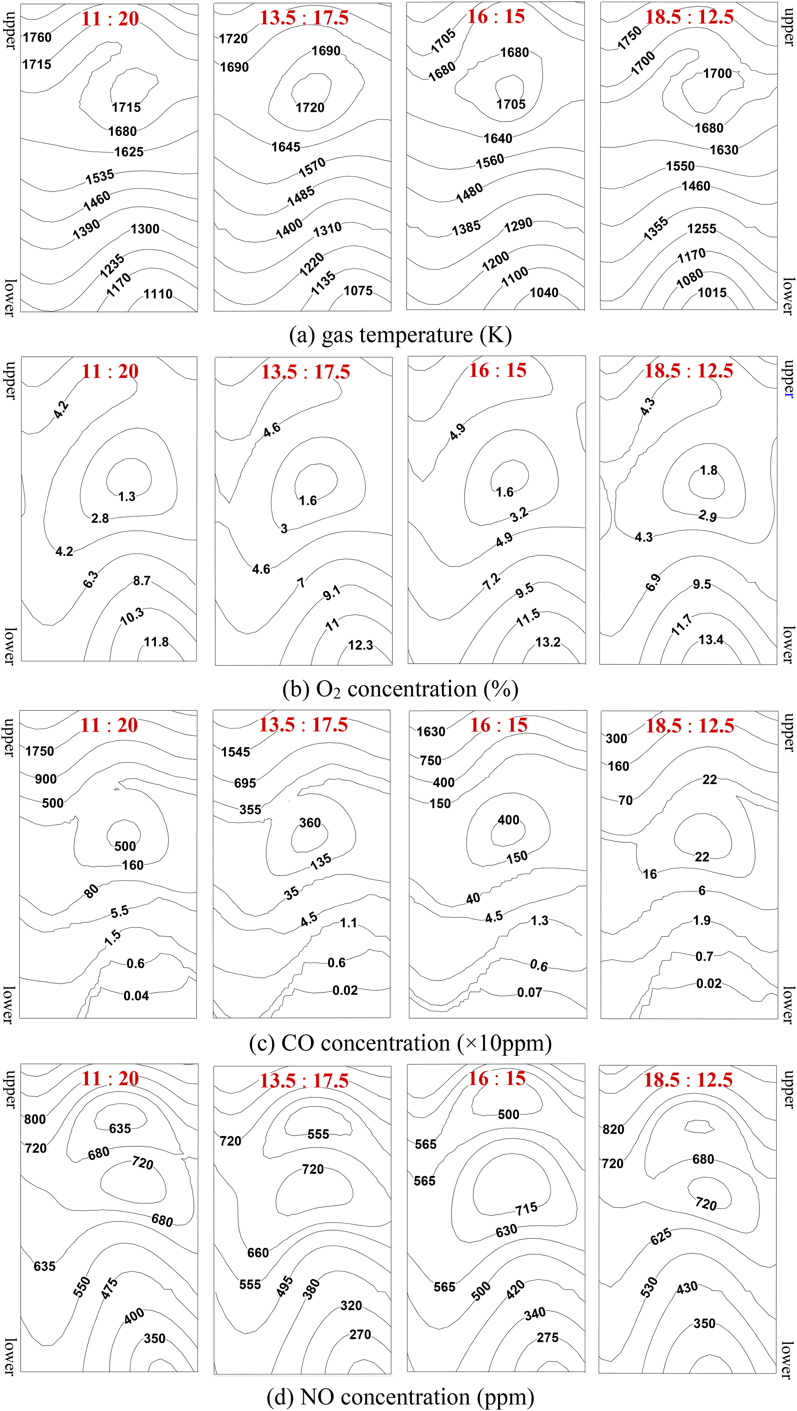
Data distributions on the vertical Section C in the hopper.
Figure 8 compares the data distributions along the horizontal Line D striding across the hopper's upper zone. From the front/rear sides to the central part, both gas temperature and NO first rise sharply and then fall to some extent. O2 initially increases a little but then decreases sharply before a final increase stage in the central part. In general, CO presents low levels at two ends, undertakes a sharp rise-to-drop stage in the side zones, and refreshes to low levels in the central part. These distribution patterns are mainly attributed to a combined effect of the line location, staged HA, upward gas, and the flame trajectory along the Line D. In detail, a combination of the UHA diffusion, wall's heat-absorption behavior, and the absence of combustion in the hopper's near-wall zone, develops such low levels of temperature, CO, and NO while high O2 at two ends of the line. Thereafter, the declinate UHA directly scours the line and mixes with the downward flame. These behaviors first raise O2 and then favor intensely the local char combustion. As a result, all of temperature, NO, and CO increase while O2 first raises a little and then declines sharply. Finally, due to (i) the UHA mixing prior to the flame reversal and (ii) the aforementioned UHA's function, O2 rise again and both gas temperature and other gas components turn to decline in the central part. According to Figure 8, with raising the HA:OFA ratio, O2 increases in the front/rear side zones and presents a drop-to-rise trend in the central part, while both gas temperature and NO generally attain an opposite trend as that of O2. CO generally decreases continuously, with the exception of the abnormal rise-to-drop stage in the rear-half side at settings of 11:20 and 18.5:12.5. Herein, the data trends with the HA:OFA ratio occur mainly because of a combined impact of the continuous HA increase and the promotion-to-attenuation combustion. The abnormal observation at settings of 11:20 and 18.5:12.5 is attributed to the poorer combustion symmetry. Aiming at pursuing symmetrical combustion, low CO for burnout, and low NO in the reversed gas in the central part, the 13.5:17.5 setting should be preferred as the HA:OFA ratio.
Data curves along the horizontal Line D in the hopper's upper zone.
Comparison of the final furnace performance
Table 1 compares various furnace-performance merits of the four HA:OFA ratios and the reference furnace reported in Liu et al. 18 With increasing the HA:OFA ratio in the SAF furnace, the residual O2 initially fluctuates slightly but then increases, both carbon in fly ash and levels of CO/NO x emissions generally decrease first and then increase. These furnace-performance trends mean that, for the SAF furnace equipped with the staged HA and OFA as the last two air-staging injections, reasonably raising the HA:OFA ratio not only drops NO x emissions but also improves burnout, while an excessive HA:OFA ratio deteriorates both two aspects. The circumstances enable the HA:OFA = 13.5:17.5 to achieve the optimal low-NO x and high-burnout merit (i.e., NO x emissions of 543 mg/m3 and carbon in fly ash of 4.89%) among the four settings. An explanation relies on several aspects: (i) as mentioned previously, with enlarging the HA:OFA ratio, all of the burnout-related components including the downward flame penetration, combustion symmetry extent, and combustion status first improve and then deteriorate, thereby yielding such a rise-to-drop burnout trend; (ii) an excessive HA:OFA ratio apparently raises the UHA flux to weaken the reductive atmosphere in the lower part of the reburning zone (Figure 4(b)), which is not conducive to NO reduction via fuel reburning. In contrast, an extremely low HA:OFA ratio such as 11:20 allows its high OFA flux to create a NO-favored environment in the burnout zone; and (iii) both the imperfect symmetrical combustion at the lowest 11:20 setting and the worsened combustion symmetry at excessive HA:OFA ratios not only strengthen the local high-temperature zones to raise NO formation, but also raise the combustion fragment in the upper furnace to weaken burnout.
Table 1 also demonstrates the merit comparison between the SAF and reference furnaces, where the SAF's low-NO x merit thoroughly defeats that of the reference furnace.11,18 Upon the NO x calculation deviation of +4.4% (determined by comparing the reference furnace's measured and simulated NO x levels, Table 1), the SAF's lowest calculated NO x emissions (i.e., 543 mg/m3) at its optimal HA:OFA ratio of 13.5:17.5 can be corrected to 518 mg/m3 in a real-furnace environment, which are much lower than the reported NO x levels in those conventional low-NO x arch-firing furnaces5,7–12,17 solely based on deep air staging and bias combustion. Compared with the still imperfect low-NO x outcome (i.e., NO x emissions of 905 mg/m3 and carbon in fly ash of 5.1%) and poor hopper environment (i.e., the particularly high temperatures and O2 respectively at 1600 K and 17% 18 ) of the reference furnace, here the SAF furnace significantly improves the furnace performance in two aspects. First, NO x emissions are sharply reduced to 543 mg/m3 and carbon in fly ash drops a little to 4.89%, meaning a further 40% NO x reduction rate plus a slight burnout improvement. This merit fully subverts the conventional understanding about low-NO x combustion where significantly reducing NO x emissions usually declines burnout, such as the low-NO x circumstances in.5,7–12,17 Second, both the overheating problem and poor air-usage environment in the hopper are resolved well by sharply declining its temperatures and O2 levels to 1100 K and 10%, respectively. In addition, here the optimal HA:OFA distribution improves further the SAF's low-NO x merit and hopper environment, in comparison to the previous SAF works18,20 with NO x emissions, carbon in fly ash, and hopper's temperatures of about 630 mg/m3, 5.3%, and 1200 K, respectively. This new progress thus highlights the importance of this work.
The significant NO x reduction and improvement in both burnout and hopper environment by using the SAF are explained as follows. First, in the NO x -reduction aspect, the SAF additionally imports FGR and fuel reburning as compared with the reference furnace. 18 Upon a combination of declining the arch-supplied air flux, applying a staged HA, and refining the HA:OFA distribution, the SAF regulates a clearly enhanced deep-air-staging environment throughout the furnace. Second, regarding the burnout improvement, the SAF relies on strengthening combustion via a staged arch form, arranging a staged HA pattern to favor char combustion, and using a throat-OFA form to improve burnout in the upper furnace. Third, with respect to the hopper-environment improvement, the SAF's contribution is depended on shortening the downward flame penetration and meanwhile raising the oxygen utilization in the hopper. That is, a combination of an arch-air flux decrease, the staged-air location elevating, a staged HA pattern, and an appropriate HA:OFA distribution removes the previous hopper-overheating environment reported in the reference furnace.11,18
Although all simulated results above have already highlighted the great superiority of the SAF in improving the low-NO x combustion performance of the reference furnace, the SAF would likely also incur shortcomings involving the complexity in the furnace configuration, combustion system, and real-furnace operation adjustments, because it applies the staged furnace-arch form and enriches the low-NO x framework. However, in order to upgrade further the high-burnout and low-NO x performance and eliminate the hopper's overheating problem, it is still necessary to pursue the SAF application in a real-furnace environment.
Conclusion
Based on a systematic evaluation of the in-furnace flow, coal combustion, NO x generation, and hopper environment under four settings of HA:OFA = 11:20, 13.5:17.5, 16:15, and 18.5:12.5, the HA:OFA ratio impact was reported for a low-NO x SAF, which was designed as a solution to a 600 MWe arch-firing furnace (i.e., the reference furnace) suffering from still high NO x and hopper's overheating environment. Major results are below.
In comparison to the reference furnace, the SAF application ended the downward flame in the hopper's upper zone, strengthened the recirculating gas below upper arches, lengthened the OFA diffusion, and improved the hopper environment by lowering levels of gas temperature and O2. As a result, the SAF contributed great benefits to various segments, i.e., strengthening combustion to improve burnout, significantly restraining NO x in all combustion stages, and greatly relieving the hopper's overheating environment. With raising the HA:OFA ratio, all of the downward flame penetration, combustion symmetry, and the combustion intensity in the lower furnace first improved and then worsened, yielding an opposite trend in the combustion fraction in the upper furnace.
The final performance indexes showed that with increasing the HA:OFA ratio, the unburnt matter in fly ash and levels of CO/NO x emissions declined first and then raised, meaning that a moderate HA:OFA ratio increase simultaneously achieved NO x reduction and burnout promotion. Among the four settings, the HA:OFA = 13.5:17.5 exhibited the best low-NO x merit with NO x emissions of 543 mg/m3 and carbon in fly ash of 4.89%. In comparison to its reference furnace, the SAF not only declined significantly NO x by 40% and improved a little burnout, but also relieved effectively the hopper's overheating environment by dropping its temperature levels by 500 K. In addition, the gained reasonable HA:OFA distribution upgraded further the SAF's low-NO x merit in comparison to the previously published investigations into the SAF. This new progress thus highlights the importance of this work.
Footnotes
Declaration of conflicting interests
The authors declared no potential conflicts of interest with respect to the research, authorship, and/or publication of this article.
Funding
The authors disclosed receipt of the following financial support for the research, authorship, and/or publication of this article: This work was supported by the National Natural Science Foundation of China, Natural Science Foundation of Ningbo Municipality, and Fundamental Research Funds for the Provincial Universities of Zhejiang (Grant Nos. 52276122, 2022J113, and SJLY2022009).