






Abstract
Nonlinear free vibration and damping of a clamped–clamped composite beam containing shape memory alloy wires with different prestrains embedded in the midsurface are investigated. The constitutive relations of shape memory alloy are considered in the large deflection response of the elastic Euler–Bernoulli beam, and Hamilton’s principle is used to derive differential equation of the beam motion with extensible midplane. Considering midplane stretching due to tension in the shape memory alloy wires provides an ability to model damping in a nonlinear analysis although there is no distinct damping expression in the governing equation of motion. The results show a gradual decrease in the free vibration amplitude of the beam until it reaches a fully elastic response while this cannot be seen in linear models. Free vibrations of the beam are investigated, and time response, phase diagram, state of stress and strain in the wires, and variations of loss factor are studied. The effect of prestrain in the shape memory alloy wires on the final stable vibration amplitude and loss factor in free vibrations of the beam is also investigated.
Introduction
The remarkable properties of shape memory alloys (SMAs), including shape memory effect and pseudoelasticity, have led to their application as sensors and actuators in various areas. They are also incorporated in smart structures to allow adaptive control of their static and dynamic behaviors. In such applications, SMAs have been utilized in various forms, including tendon (Speichera et al., 2011), thin film (Kniknie et al., 2010), and spring (Zhu et al., 2011). However, they have been widely used in the form of wire, and dynamic behavior of SMA wires (Kadkhodaei et al., 2007) and beams with embedded SMA wires (Dos Reis et al., 2010) have received special attention in recent years.
Vibration of an SMA-reinforced composite beam was investigated by Baz et al. (1995). They showed that natural frequencies of a beam can be controlled by the use of SMA wires. According to the results reported by Lau et al. (2002), if prestrained SMA wires are embedded into a composite beam, the generated recovery stress has a significant effect on the natural frequencies of the whole beam. When SMAs are embedded in a vibrating beam, damping is seen in the beam motion due to energy dissipation caused by the hysteresis in the SMA response. Gandhi and Chapus (2002) and Collet et al. (2001) employed finite element method using amplitude-dependent complex Young’s modulus to show that damping and frequency in vibrating SMA wires are strongly amplitude dependent. This amplitude dependency indicates that, by using a linear model, one cannot study damping of the beams with embedded SMA wires in the midsurface. Some linear models are proposed to study damping in SMA-reinforced beams, but they are for the cases where stiffness-proportional damping (Hashemi and Khadem, 2006) or environmental damping (Qingquan et al., 2008) already exists in the structure.
In this article, nonlinear free vibrations of a clamped–clamped composite beam with prestrained SMA wires are studied with special emphasis on damping behavior. All the wires are embedded in the midplane of the beam and are constrained between two supports. Large deflection beam analysis is implemented in order for the geometric nonlinearity to be considered in the model. As the SMA response under thermomechanical loads is nonlinear, hysteretic, and path dependent, material nonlinearity is also taken into account. Considering the effect of axial force due to midplane stretching, the Euler–Bernoulli beam theory is utilized, and the nonlinear equation of motion is derived using Hamilton’s principle. Galerkin’s method is used to discretize the nonlinear partial differential equation of motion. Although no damping can be seen in a linear analysis, the present nonlinear model is able to predict inherent damping due to the SMA wires. Free vibrations are investigated, and time response, the corresponding phase diagram, and state of stress and strain in the wires are studied. Moreover, the effects of initial conditions, number of embedded SMA wires, temperature, and prestrain on loss factor are investigated. To the authors’ knowledge, the effect of prestrain and axial force on the nonlinear free vibrations of SMA-reinforced beams has not been reported yet.
Constitutive model of SMA
The one-dimensional constitutive model proposed by Brinson (1993) and Brinson and Huang (1996) is used to express the relationship between strain and stress of SMA at different temperatures. This model can be stated as
where
in which
where
In this article, the SMA wires are employed in their pseudoelastic state where forward and backward transformations may take place. Referring to Figure 1, during conversion of austenite to martensite where

Critical transformation stresses.
For reverse transformation from martensite to austenite where
The subscript “0” refers to the initial conditions prior to the current transformation.
Equation of motion
A clamped–clamped composite beam of length L with uniformly embedded SMA wires within the midplane is considered as shown in Figure 2 from different views. Transverse vibrations of the beam produce midplane stretching. When considering the effect of axial force due to the midplane stretching, the SMA wires have considerable contribution in the generated force, which depends on the beam deflection.

A schematic of the SMA-reinforced beam.
To derive the equation of the beam transverse vibration, a differential element of length dx is considered at point P(x,0) in the undeformed configuration of the beam according to Figure 3. The beam is modeled according to Euler–Bernoulli theory. The axial and transverse displacements are denoted by u and w, respectively, both of which are functions of the spatial coordinate x. After deformation, point P moves to a new location P*(x * ,y * ) where

A differential element of the beam before and after deformation.
In Figure 3, ds is the length of the element in the deformed configuration and is expressed as
Differentiating equations (6) and (7) with respect to x yields
and
where “” denotes derivative with respect to x. Therefore, the length of the element in the deformed configuration can be expressed as
Elongation of the differential element is
Expanding equation (12) in a binomial series yields
Neglecting the higher order terms, the following equation is obtained (Nayfeh and Mook, 1979)
Integrating equation (14) over the domain, the beam’s midplane stretching is
where u(L) and u(0) are axial displacements at the two ends of the beam that are zero for the fixed ends.
It is assumed that there is no slip between the SMA wires and the beam, so the strain in the wires is equal to that in the midplane of the beam. Also, stress is assumed to be equally divided among the wires. The induced axial force due to the midplane stretching, S, is composed of restoring force due to stretching in the SMA wires and that in the composite material, and it can be expressed as
where
Potential energy due to bending is given by
in which
Potential energy due to midplane stretching is expressed as
Therefore, the total potential energy that is the sum of
The kinetic energy of the beam is
where
To derive the beam equation of motion, Hamilton’s principle is used in the form of (Meirovitch, 2000)
in which
where q(x,t) is the distributed load in the transverse direction. Corresponding boundary conditions for a clamped–clamped beam are:
The solution of equation (23) can be expressed as
in which s(t) is the first generalized coordinate and W(x) is the shape function given as (Meirovitch, 2000)
Galerkin’s method is applied to reduce the partial differential equation of motion to an ordinary differential equation. Equation (25) is thus substituted into equation (23), and the resultant expression is multiplied by equation (26). Subsequent integration over the length of the beam yields the nonlinear differential equation of motion as
where
Coefficient a represents square root of the linear fundamental natural frequency of the beam, and b is due to midplane stretching in the beam whose origin comes from the nature of the clamped–clamped boundary conditions.
Numerical analysis
The equation of motion may be rewritten as a first-order system of equations, assuming
The system of equations is numerically solved by employing a fourth-order Runge–Kutta scheme, and quantities including strain and martensite fraction are updated in every step of the solution. Two composites epoxy/glass and epoxy/carbon are selected for the beam material, and Nitinol is chosen for the SMA wires. The corresponding material properties as well as the dimensions of the beam and the wires are listed in Tables 1 to 3. In the following, free vibrations of a composite beam containing SMA wires with no prestrain (
Material properties of the SMA.
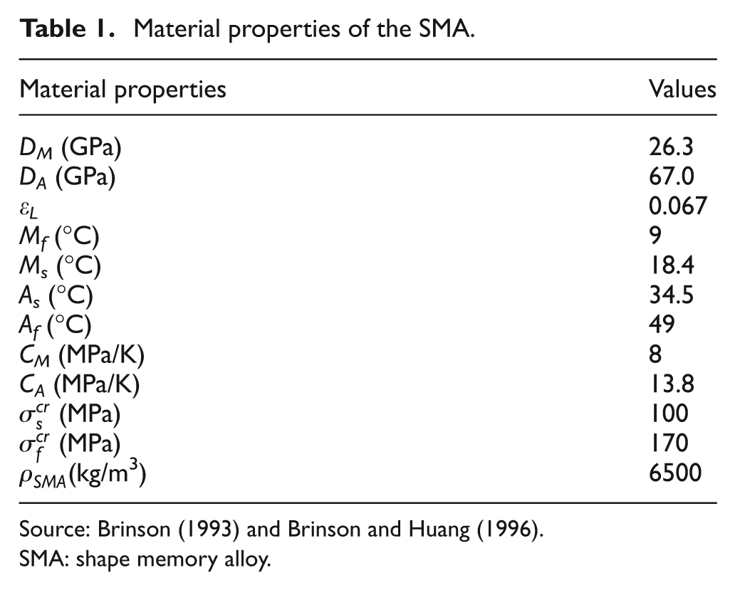
Source: Brinson (1993) and Brinson and Huang (1996).
SMA: shape memory alloy.
Material properties of the beam.

Dimensions of the beam and SMA wires.

SMA: shape memory alloy.
Figure 4 shows the free vibration response and corresponding phase diagram for an epoxy/glass beam with no embedded SMA wires. The initial conditions are assumed as (s1, s2) = (0, 220). As can be seen in Figure 4(a), the time response shows no decrease in the vibration amplitude since in this case the beam is an elastic vibrating structure. The phase diagram, shown in Figure 4(b), confirms this as it is an orbit representing vibration without damping.

Free vibrations of a beam with no SMA wire for (s1, s2) = (0, 220): (a) time response and (b) phase diagram.
Figure 5(a) shows time response of the beam when 20 SMA wires at the temperature of 50°C are embedded in its midplane. At this temperature, the wires are in austenite phase when placed inside the beam. Initial conditions, which are the same as those in Figure 4, are so that complete transformation from austenite to martensite starts at the beginning of the motion. Thus the hysteresis loop causes drastic decrease in the vibration amplitude of the beam. By decreasing the vibration amplitude, strain in the SMA wires is not high enough to generate the critical stress necessary for complete transformation. Thus, the maximum martensite fraction decreases, as shown in Figure 5(b), and incomplete hysteresis loops appear in the SMA stress–strain response by the passage of time, as shown in Figure 5(c). This procedure continues until the vibration amplitude is not able to induce any transformation in the wires so that only the elastic response of SMA in its austenite phase is activated. Hence, the whole beam vibrates elastically with constant amplitude. Figure 5(d) shows the phase diagram, which indicates a dissipative response converging to a limit cycle.

Free vibrations of the beam containing 20 SMA wires with no prestrain at 50°C for (s1, s2) = (0, 220): (a) time response, (b) variations of martensite fraction with time, (c) stress–strain curves of the SMA wires beginning from point A, and (d) phase diagram.
Logarithmic decrement formula can be used as a measure to calculate the loss factor (Meirovitch, 2000)
in which
In Figure 6, variation of the loss factor with the number of embedded SMA wires for two different composite beams at 50°C is shown. The initial conditions are assumed as (s1, s2) = (0, 220). By increasing the number of SMA wires, due to more energy dissipation, more decrease in the vibration amplitude is achieved leading to the increase of the loss factor. As it is seen, the Young’s modulus of the beam also affects the amount of loss factor. For epoxy/carbon whose elastic modulus is greater than that of the SMA, the restoring force generated by the wires is less than the force generated due to the stretching in the composite material. However, converse relation holds for epoxy/glass whose elastic modulus is smaller than that of the SMA. Therefore, the resultant loss factor in the epoxy/carbon beam is less than that in the epoxy/glass one for any number of embedded SMA wires.

Loss factor of SMA-reinforced composite beams with different number of SMA wires with no prestrain at 50°C for (s1, s2) = (0, 220).
To study the effect of the initial conditions, three different initial velocities are considered in Figures 7 to 9 for an epoxy/glass beam containing 25 SMA wires at 50°C. Figure 7(a) to (c) shows the time response, stress–strain diagram of SMA, and phase diagram for the beam with (s1, s2) = (0, 200), respectively. In this case, at the beginning of the vibration, strain in the midplane induces complete forward phase transformation in the wires. Thus, energy dissipation occurs at the early instances of vibration due to the hysteresis loops in the stress–strain response of the wires. However, according to the explanations provided for Figure 5, after a short while, the SMA response becomes elastic with no phase transformation causing constant vibration amplitude for the whole beam. The time response, stress–strain diagram, and phase diagram for the beam with (s1, s2) = (0, 100) are shown in Figure 8(a) to (c), respectively. These initial conditions induce partial phase transformation at the beginning of the vibration. Consequently, smaller hysteresis loops are observed in the results. If the initial velocity is not enough to generate necessary strain for the initiation of the phase transformation in the SMA wires, the whole beam behaves elastically with no damping from the start of the motion. Such a case is studied in Figure 9(a) to (c) for the beam with (s1, s2) = (0, 10). In Figure 10, variation of the loss factor with the initial velocity is presented for an SMA-reinforced epoxy/glass beam. If the initial velocity increases from the amounts not inducing any phase transformation in the SMA wires, by reaching to the velocities capable of inducing phase transformation, the loss factor is first increased due to the energy dissipation. However, beyond some specific velocity, the loss factor decreases with increase in the initial velocity. This is due to the fact that increasing the initial velocity increases the vibration amplitudes as well as decreases the rate of amplitude reduction although it gives rise to completeness of the phase transformations. In other words, both very low and very high initial velocities result in small loss factors due to the weakened effect of the SMA wires and less decreases in the successive vibration amplitudes, respectively. For instance, comparison of Figures 5 and 7 shows that complete transformation occurs at the beginning of vibrations for both s2 values of 200 and 220, but Figure 10 shows that the loss factor obtained for the case s2 = 220 is smaller than that for the case s2 = 200. Consequently, an optimal initial velocity exists in which the loss factor is maximum.

Free vibrations of the beam containing 25 SMA wires with no prestrain at 50°C for (s1, s2) = (0, 200): (a) time response, (b) stress–strain diagram of SMA wires beginning from point A, and (c) phase diagram.

Free vibrations of the beam containing 25 SMA wires with no prestrain at 50°C for (s1, s2) = (0, 100): (a) time response, (b) stress–strain diagram of SMA wires beginning from point A, and (c) phase diagram.

Free vibrations of the beam containing 25 SMA wires with no prestrain at 50°C for (s1, s2)= (0, 10): (a) time response, (b) stress–strain diagram of SMA wires beginning from point A, and (c) phase diagram.

Variations of loss factor with initial velocity for the epoxy/glass beam containing 25 SMA wires with no prestrain at 50°C for s1 = 0.
Figure 11 represents the effect of temperature on the loss factor for a vibrating epoxy/glass beam with the initial conditions (s1, s2) = (0, 220), reinforced with 25 SMA wires. At all of the temperatures studied in Figure 11, the wires are in austenite phase when embedded in the beam. By increasing the temperature, due to the increase in the transformation stresses according to Figure 1, the necessary strain to initiate transformation increases. Moreover, for the studied SMA, increase of the temperature causes the critical stresses of the forward and backward transformations to be closer to each other as C A is greater than C M , and hence, narrower hysteresis loop is achieved. Accordingly, the effect of hysteresis loop weakens leading to the decrease of the loss factor.

Variations of loss factor with temperature for the epoxy/glass beam containing 25 SMA wires with no prestrain at 50°C for (s1, s2) = (0, 220).
If the SMA wires are first prestrained at low temperatures when they are in martensite phase and then heated to above A s , when embedded in the clamped–clamped beam, a recovery stress is generated in the installed wires due to the constraints on both ends of the beam. Shown in Figure 12 are variations of the recovery stress with temperature for SMA wires inserted with different amounts of prestrain. In Figure 12, the SMA response starts from zero stress state with some initial detwinned martensite volume fraction corresponding to the amount of prestrain. Since the thermal strains are negligible in comparison to the transformation strains, no significant change in the stress or the volume fraction occurs during heating until temperature reaches A s . At this temperature, the SMA response enters the reverse transformation strip [A], and the martensite volume fraction begins to decrease while the stress begins to increase due to the fixed strain during heating. As it is seen in Figure 12, the increase of the recovery stress stops if heating continues, so that the SMA response exits from the reverse transformation strip. At such a high temperature, the wires are in full austenite phase but subjected to prestress prior to the start of vibrations. Consequently, compared to the cases in which the wires are embedded with no prestrain, a larger restoring force that leads to more considerable effects of the SMA is produced when the beam vibrates.

Variations of recovery stress with temperature for different amounts of prestrain in SMA.
To investigate the effect of prestress resulting from prestrain in the wires, response of a prestrained SMA wire during free vibrations of an epoxy/glass beam is shown in Figure 13. The wire is embedded with 0.4% prestrain, and the beam begins to vibrate when the temperature is raised to 70°C with the initial conditions (s1, s2) = (0, 220). As can be seen in Figure 13, the stress–strain response of the wire starts from point A where the SMA is in austenite phase. Due to the nonzero initial stress and strain of the wire, less strain due to the beam vibrations is needed to induce phase transformation. In other words, transformations in the SMA occur more easily causing the portion of the elastic response to be reduced and, hence, the effect of the hysteresis loop to be increased. Therefore, damping effects of the SMA wires are more pronounced in free vibrations of a beam inside which the prestrained wires are embedded. In Figure 14, the free vibration response of an epoxy/glass beam containing 25 SMA wires with 0.4% prestrain at 70°C is compared with that of the beam when the wires are embedded with no prestrain. As it is seen, existence of the prestrain makes more reduction in the amount of vibration amplitude, and this effect increases with time so that a more evident difference is seen in the stable amplitude.

Stress–strain diagram of SMA wires beginning from point A with 0.4% prestrain at 70°C for (s1, s2)=(0, 220).

Time response of the beam containing 25 SMA wires with two different prestrains at 70°C for (s1, s2) = (0, 220).
Figure 15(a) and (b) shows the variations of stable vibration amplitudes and the loss factors with respect to prestrain for different temperatures and the same initial conditions (s1, s2) = (0, 220) for an epoxy/glass beam, respectively. In all these cases, the amounts of temperature and prestrain are so that the SMA wires are in full austenite phase at the onset of the free vibrations. In such conditions, for any specified temperature, smaller amount of stable vibration amplitude as well as higher loss factor is achieved by increasing the SMA prestrain. This behavior is predictable according to the explanations provided for Figures 13 and 14. However, for any desired prestrain, increase in the temperature causes the final amplitude to be increased and the loss factor to be decreased. As it was discussed for Figure 11, increase in the transformation stresses and strains as well as decrease in the difference between the critical stresses of the forward and backward transformations leads to decrease in the effect of the SMA hysteresis loop by increasing the temperature. Consequently, regardless of the amount of prestrain in the embedded SMA wires, temperature has an inverse effect on the damping of the SMA.

Variations of (a) the stable vibration amplitude and (b) loss factor with the amount of prestrain in the SMA wires for the epoxy/glass beam containing 25 wires at different temperatures for (s1, s2)= (0, 220).
Conclusion
In this article, nonlinear free vibration and damping of a clamped–clamped beam with prestrained SMA wires embedded in the midsurface are analyzed. To take both geometric and material nonlinearities into account, the constitutive relations of SMA are considered in the large deflection response of the elastic Euler–Bernoulli beam. Hamilton’s principle is used to derive differential equation of motion for the beam with extensible midplane. The nonlinear partial differential equation of motion is numerically solved with the use of Galerkin’s method. Time responses and the corresponding phase diagrams, state of stress and strain in the SMA wires, and variations of loss factor for different conditions are investigated. The results show that the mechanical properties of the beam and SMA wires, number of embedded wires, amount of prestrain in the wires, temperature, and initial conditions of motion have significant effects on the vibration behavior and damping properties of the composite beam. Although there is no distinct damping expression in the governing equation of motion, the proposed nonlinear model can predict inherent damping due to energy dissipation in the embedded SMA wires, while this cannot be seen in the linear analyses.
Footnotes
Nomenclature
A c is the cross-section area of the beam
A f is the austenite final temperature
A s is the austenite start temperature
A SMA is the total cross-section area of all the SMA wires
C A is the slope of the backward transformation strip
C M is the slope of the forward transformation strip
D is the Young’s modulus of SMA
D A is the austenite Young’s modulus
D M is the martensite Young’s modulus
E c is the composite Young’s modulus
e is the elongation of the differential element
I c is the moment of inertia of the beam
I SMA is the total moment of inertia of all the SMA wires
K is the kinetic energy of the beam
L is the beam length
M s is the martensite start temperature
M f is the martensite final temperature
q(x,t) is the distributed load in the transverse direction
s1(t) is the first generalized coordinate
s2(t) is the time derivation of s1
T is the temperature
u is the axial displacement of the beam
V is the total potential energy of the beam
w is the lateral deflection of the beam
Greek letters
Funding
This research received no specific grant from any funding agency in the public, commercial, or not-for-profit sectors.