
Abstract
This article presents the conceptual design, modelling, prototyping and testing of a novel rotary motor featuring shape memory alloy wires and overrunning clutches. The device comprises a shape memory alloy wire wound around a low-friction cylindrical drum contrasted by a backup beam spring and fitted to the output shaft through an overrunning clutch. Electrical heating produces a contraction of the wire, hence a rotation of the drum which is transferred to the shaft. Thanks to the overrunning clutch, during the recoiling phase, the drum rotates backward while the shaft does not move. Spurious backward movements of the shaft are contrasted by a second overrunning clutch linking the shaft to the frame. This article develops a model for the quasi-static simulation of the motor and the experimental characterization of a prototype device featuring three active drums, a rotary sensor and an angular brake to apply the external load. Despite the low degree of optimization, the tested motor performs well in terms of specific stroke, specific output torque and specific output work per cycle. Winding of the wire on the drum impairs somewhat the fatigue life with respect to publish data on straight wires, a drawback which calls for further design refinements.
Introduction
High-power density, smooth and silent operation, mechanical simplicity and compatibility with aggressive environments are but a few from a long list of advantages that make shape memory alloy (SMA) actuators strong competitors to conventional drives in many industrial applications. A relatively unexplored field for the exploitation of the shape memory technology is the area of rotary actuators, especially for generating multiple revolutions or endless rotations. Fields of application for low-speed, unidirectional actuators are, among others, towel dispensers, peristaltic pumps, conveyor belts, rotary positioning tables, toy motors, rotating beacons, pencil sharpeners and turnspit drives.
Shape memory torsion tubes are the favourite concept for rotary shape memory actuators due to their simple geometry and high output torque (Friedman et al., 2011; Keefe and Carman, 2000; Mehrabi et al., 2015). Using thin-walled tubes, all the material work is transferred directly to output energy and the part count is very low. A simple gear reduction is all that is needed to get large, though not endless, rotations from a modest size tube. Many engineered solutions based on torsion tubes have been developed and implemented for the aeronautical industry (Calkins and Mabe, 2010) mainly thanks to the work by the Boeing Company (Bushnell and Whitley, 2007; Gunter, 2014; Jacot et al., 2000, 2002; Mabe et al., 2011). The main hindrance to adopting SMA tubes is represented by the need to heat the alloy by electric blankets, fluid flow or thermoelectric modules (Caldwell et al., 2007) instead of direct current supply as for the wires.
The simplest, strongest and most efficient SMA elements that can be used in practice are the drawn wires, commercially available in a wide range of diameters and physical properties. The main issue in using SMA wires for rotary actuation is the need to convert the linear motion, intrinsic to the wires, into an angular movement. Marketed rotary actuators make this conversion either by means of antagonistic wires wound onto a rotating shaft (http://www.toki.co.jp/biometal) or by coupling a linear shape memory actuator with a spring-loaded, cam-action rotary output (http://www.migamotors.com/index.php?main_page=product_info&cPath=1&products_id=29). Jansen et al. (2004) developed an integrated positioning actuator using two SMA wires wound antagonistically onto an output shaft. A brake-assisted mechanism activated by a third SMA wire and released by a fourth SMA wire was provided to ensure stability of intermediate positions. A modular architecture comprising several units was envisioned to adapt the concept to a wider field of applications. A modular approach was adopted also by Spinella et al. (2009) where the basic module contained a moving rotor actuated tangentially by four shape memory springs. The solution by Spinella et al. (2009) contains also a first instance of elastic compensation performed by means of an elastic spring that reduced the torque ripple of the single module. Lan et al. (2009) presented the design and implementation of a rotary manipulator combining SMA wires and flexural beams. Both one-way and two-way wheel-like manipulators were validated, in which the outer rim of the wheel was connected by three compliant sprockets to the centre shaft. Tangential forces were provided by SMA wires connecting the midpoints of each sprocket to the outer rim. Upon deactivation of the wires, the internal elastic force returned the sprockets to their original positions. Although mechanically simple, the concepts described above have severe limitations in the output rotation (60° is the maximum claimed rotary stroke) and cannot by any means provide unlimited angular motion.
In the early 2000s, Yoshida (2002) proposed a continuous rotary actuator formed by an inner disc rotating around a main shaft. The inner drum was connected to an outer casing through two spiral springs, which were wound in opposite directions and could unwind to recoil when electrically heated. Ratchet gears were provided between drum and casing to allow continuous motion. The merits of ratchet architectures for producing large strokes from compact packages in SMA actuators were recently addressed by Kim et al. (2013) in a fairly general way. Scalable bi-directional rotary actuators were designed by Park et al. (2001) using SMA wires with diameter of about 100 µm. Based on this bi-directional actuator, SMA ratchet mechanisms with minimum feature sizes of about 200 µm were developed transforming the alternated angular motion to continuously rotating motion. Pöhlau and Meier (2004) suggested a high-torque drive powered by six pairs of SMA actuators positioned radially inside a flexible gear wheel with external teeth. The flexible wheel was meshed with an outer gear wheel with internal teeth. Activating the pairs of SMA wires sequentially produced a strain wave in the internal wheel which induced continuous rotation of the external wheel much in the way a harmonic drive does. The conceptual design, mathematical modelling and experimental testing of an SMA Poly Phase motor was presented by Sharma et al. (2008). Three identical SMA wires in series with identical elastic springs (forming the three phases of the motor) were fixed to the end point of a crank and the other ends of the springs were connected to fixed points, spaced 120° apart. By activating the SMA wires sequentially, a bi-directional continuous rotation of the crank could be achieved with net output torque. Zhang and Yan (2012) modelled and characterized a low-speed, high-torque continuous rotary motor actuated by multiple segments of SMA wires. The requirements of continuous rotation were met by coupling in series five unidirectional rotary actuators, actuated sequentially. Each actuator achieved the unidirectional rotation by exploiting the irreversibility of motion between a ratchet wheel and two friction pawls, one used to receive the tangential force of the SMA wires and the other used as stalling device. Hwang and Higuchi (2014a, 2014b) proposed a cycloidal wobble motor driven by SMA wires. The applied driving mechanism consisted of a pin/roller-based annular gear as a wobbler, a cycloidal disc as a rotor and crankshafts to guide the eccentric wobbling motion. The wobbling motion of the annular gear was generated by sequential activation of radially placed SMA wires backed up by elastic springs. The cycloidal disc was rotated by rolling-contact-based cycloidal gearing placed between the wobbler and the rotor. Although continuous and sometimes characterized by high output torque, the above-mentioned SMA motors are marred by the complexity of the mechanisms used to convert the reciprocating elongation of the wires into unlimited angular rotation.
To overcome the limitations of the published solutions, this article presents the conceptual design, modelling and prototyping of a novel rotary motor based on SMA wires, coiling drums and overrunning clutches. The basic module of the device capitalizes on a SMA wire wound around a low-friction cylindrical drum according to a concept originally proposed by Song (2007). The drum is coupled with a set of overrunning clutches as explained in the following section. This combination of elements produces a rotary actuator with high output torque and virtually infinite angular stroke (motor). The model developed and the proof of concept described in this article demonstrate the potential of this idea to be converted into a compact, robust and efficient rotary motor with unlimited output stroke.
Architecture of the rotary motor
The rotary motor described in this article merges wire-on-drum actuators (Scirè Mammano and Dragoni, 2011b; Song, 2007) with overrunning clutches (Shigley et al., 2004) to exploit the advantages of both devices.
Figure 1 shows the concept of a wire-on-drum actuator. The SMA wire W is wound onto the low-friction drum D and is fixed in c to the drum itself and in e to the frame F. The drum can rotate freely about the axis a–b so that the tension force in the wire is contrasted by the compression force in the elastic spring S, also attached between drum and frame. Upon activation/deactivation of the wire, the wire slips over the drum and the inner attachment point c reciprocates between the positions c and c′ so that the drum oscillates by the angle Δα.
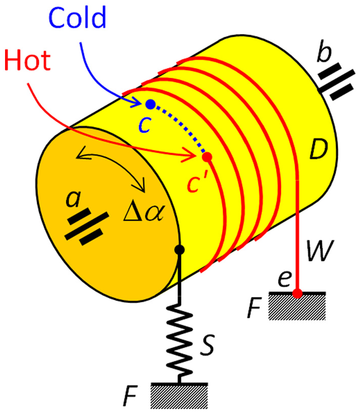
Concept of the reciprocating wire-on-drum actuator (Scirè Mammano and Dragoni, 2011b).
An overrunning clutch is a device in a transmission that disengages the driveshaft from the driven shaft when the driven shaft rotates faster than the driveshaft. Among the many practical instances available from the market (Shigley et al., 2004), Figure 2(a) exemplifies one particular type of overrunning clutch based on the sphere-socket concept. Figure 2(b) shows the symbolic representation of the device which will be adopted in the following description of the motor, regardless of the specific way to realize the device.
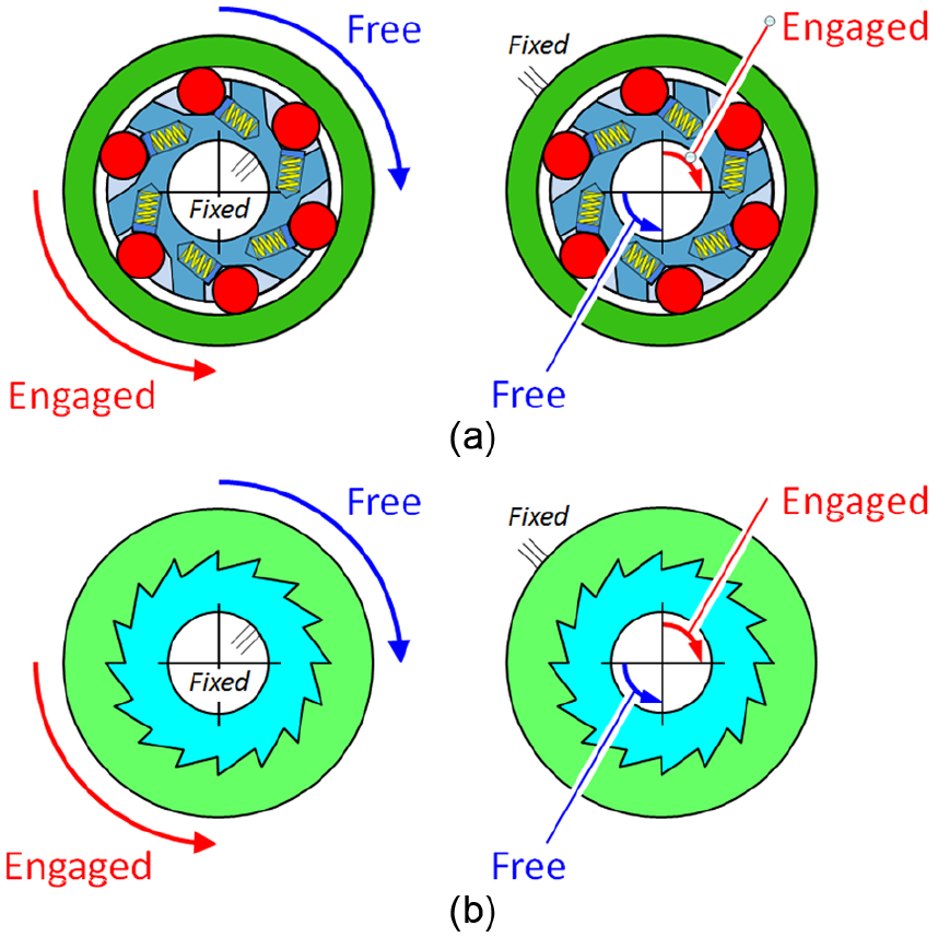
(a) Embodiment of an overrunning clutch with fixed inner or outer ring and (b) corresponding symbolic representation of the device.
Figure 3 shows the conceptual architecture of the motor. The main shaft, S, is coupled to the frame, F, by means of the primary overrunning clutch, C1, which allows only clockwise rotations of the shaft. The other end of the shaft is fitted with a second overrunning clutch, C2, mounted with the same orientation as C1 (if the outer ring of C2 is held stationary, the shaft can rotate only clockwise). A low-friction drum D, fixed to the outer ring of C2, receives several tightly wound turns of the pre-stretched SMA wire, W, the ends of which are attached to the drum, D, and frame, F. The winding orientation of the SMA wire is such that, upon contraction of the wire (activation of the motor), a clockwise torque is applied to the drum, D. Thanks to the engaged overrunning clutch, C2, the clockwise torque is ultimately transferred to the shaft, S, which is free to rotate because of the particular orientation of the first overrunning clutch, C1.
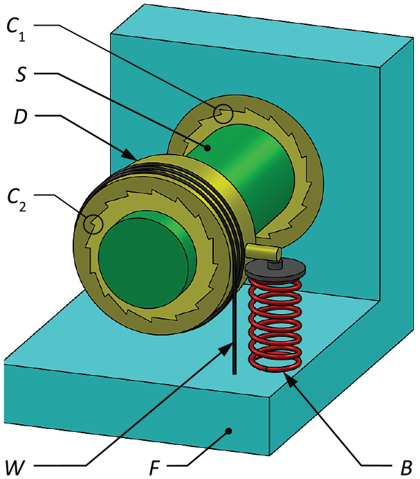
Concept of the rotary motor.
Tangentially on the drum, D, is also acting the elastic compression spring, B, which applies a counterclockwise backup torque to the system. The torque applied by the spring B must be large enough to overcome the torque of the martensite wire when it is in the cool, deactivated state. If this is the case, the counterclockwise rotation of the drum is allowed by the overrunning clutch C2, while the clutch C1 prevents any spurious counter-rotation of the shaft with respect to the frame. In principle, the overrunning clutch C1 is not strictly necessary and it could be replaced by a conventional rolling-contact bearing. However, during the backward rotation of the drum upon cooling of the wire, the internal frictional torque of clutch C2 could promote backward motion of the shaft. The overrunning clutch C1 basically prevents this unwanted reverse rotation.
In summary, once the pre-stretched wire has been tightly wound on the drum, the unidirectional clockwise rotation of the shaft is obtained by repeating two-step cycles of alternated heating and cooling of the wire. During heating, which is conveniently achieved by Joule effect through electric current supply, the wire contracts and effectively rotates the drum and the shaft clockwise. During cooling, which is improved by direct contact of the wire with the drum, the backup spring rotates the drum counterclockwise, thus elongating the memory wire while the shaft remains still. At the end of cooling step, the motor is ready to perform another cycle. Depending on the timing of actuation and number of cycles the drum could heat up as well, which would be detrimental to cooling. This issue is addressed in the second last paragraph of section ‘Discussion’.
The sub-system comprising the SMA wire, W, the backup spring, B, the drum, D, and the overrunning clutch, C2, represents the unit power module of the motor. The shaft, S, embodies the output port of the motor. Of course, several unit modules can be arranged on a single output shaft, as shown in Figure 4 for a three-stage motor, and activated in several possible ways. Serial activation of the modules (i.e. by cycling them one after the other) results in a smoother rotation of the output shaft with respect to a single-stage motor. Similarly, parallel activation of the modules (cycling them simultaneously) increases the output torque while conserving the step-wise rotation of the unit stage. If the number of modules is large (three or more), it is also possible to combine serial and parallel activation of subsets of modules and also partially overlap the cycle time of the modules within each subset. This produces concurrent increase in output torque and improved regularity of the rotation.

Example of a three-stage rotary motor.
Modelling of the unit module
This section presents the analytical model of the unit module of the motor (dashed box in Figure 4) in terms of angular displacements produced by activating the SMA wire for any given externally applied torque. The model is based on the theory developed by Scirè Mammano and Dragoni (2011b) for the case of a SMA wire wound on a low-friction cylindrical drum and contrasted by a constant force. That theory is applied here to the unit module by assuming that the backup spring (B in Figure 3) generates a constant force and, consequently, the drum D receives a constant external torque. As widely recognized (Scirè Mammano and Dragoni, 2011a), the constant backup force (zero backup stiffness) improves the performance of the actuator with respect to a linear backup force (constant stiffness). For this application, a nearly zero-stiffness condition is achieved using a thin beam loaded axially beyond its buckling limit (Berselli et al., 2014).
The wire-on-drum model developed by Scirè Mammano and Dragoni (2011b) assumes a linear elastic stress–strain response of the shape memory wire in the austenite state and a bilinear response in the martensite state as shown in Figure 5 (for details on this simple yet realistic material model, see Scirè Mammano and Dragoni, 2011a). The relationship between applied torque and angular rotation of the drum following this assumption is based on the differential elongation of the wire in the two limit states of fully transformed austenite and fully transformed martensite. The behaviour of the device for partial degrees of transformation is not taken into consideration.
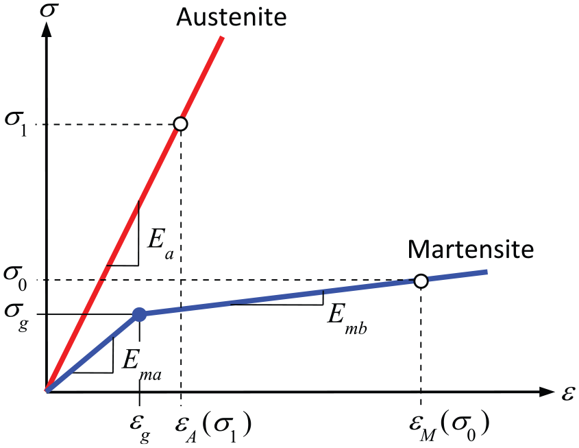
Material model of the SMA wire in austenitic and martensitic states.
Central to the determination of the austenite and martensite elongations of the wire is the stress acting in the wire due to the torques acting on the drum in the two material states. Upon activation, the stress in the austenite wire, σ1, is (see Figure 3)
where R is the winding radius of the wire, Aw is the cross-sectional area of the wire, T1 is the friction torque of the overrunning clutch C1, TL is the externally applied torque and Tb = Fb·rb is the restoring torque generated by the backup spring B (Fb is the constant backup force and rb is the arm of Fb with respect to the axis of rotation of the drum).
Upon deactivation, the stress σ0 in the martensitic wire is
where T2 is the friction torque of the overrunning clutch C2. Both stresses σ1 and σ0 are measured in the free wire length comprised between the frame and the drum in Figure 3.
Following Scirè Mammano and Dragoni (2011b), the elongation ΔLm of the martensite wire in contact with the drum produced by the stress σ0 is
in which Ema is the elastic modulus of the martensite, sm = Emb/Ema is the characteristic ratio between pseudoplastic and elastic martensitic moduli, f is the frictional coefficient between wire and drum, z = σg/σ0 is the ratio between the martensite yield stress and the overall stress in the wire, αA is the winding angle and αg is the portion of αA over which the wire is stressed beyond σg (yielded wire). Angle αg has the following expression
In equations (3) and (4) and in the remainder of the article, the Boolean operator 〈expression〉 is used, which assumes the values 1 or 0 according to whether expression is true or false.
When the wire is activated and the alloy transforms from martensite to austenite, the stress in the free wire switches from σ0 to σ1 and the stress in the wound wire, σc, increases with the winding angle α according to the following exponential law

The model by Scirè Mammano and Dragoni (2011b) shows that the net rotation angle of the drum, Δα, following recovery of the strain upon martensite to austenite transformation is given by either of the following two values Δα1 and Δα2
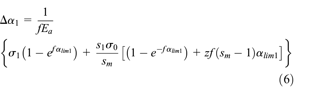

where

and
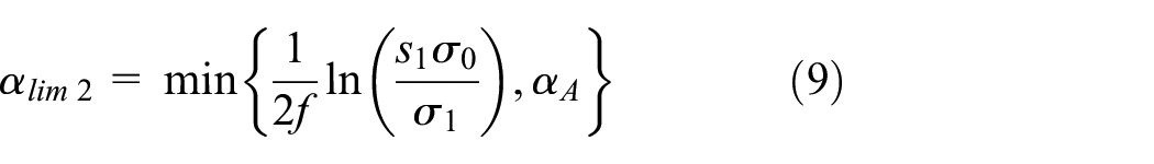
are alternative winding angles over which the strain in the wire is actually recovered, Ea is the elastic modulus of the austenite wire and s1 = Ea/Ema is a characteristic elastic ratio of the alloy.
The flowchart in Figure 6 summarizes the procedure used to calculate the maximum wire elongation and the effective rotation of the motor from the equations presented above. Figure 7 plots the net rotation of the drum, Δα, as a function of the frictional coefficient and the number of wound coils, n, for a wire stretched with an initial martensite strain of εM = 5% (see Figure 5). It is seen that the efficiency of the device increases exponentially as the coefficient of friction approaches zero.
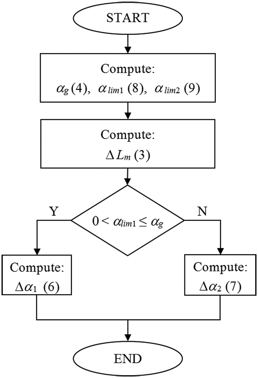
Flowchart of the logical steps for calculating the angular stroke of the motor.
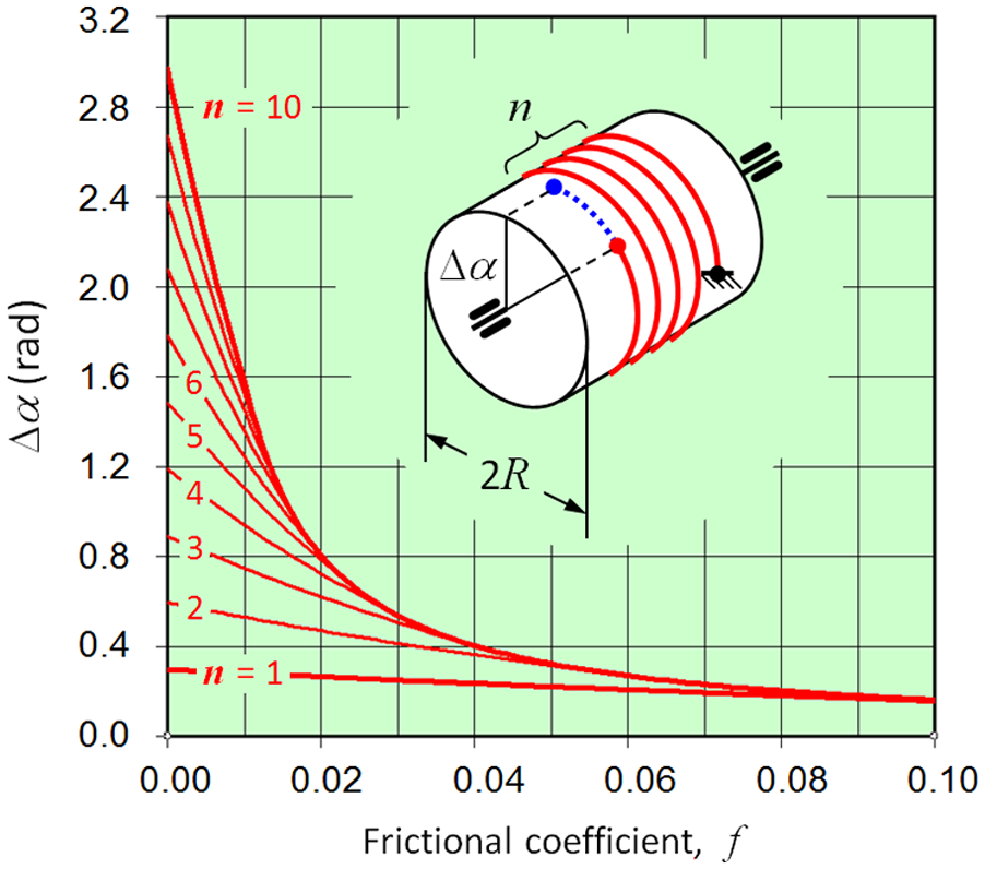
Net rotation of the wire-on-drum actuator for a martensite strain εM = 5%.
Design of prototype and test bench
Motor architecture
For the prototype motor, the architecture with three unit modules shown in Figure 4 was chosen. The modules were operated sequentially to increase the regularity and the mean speed of the output shaft. A sensor for measuring the output rotation and a brake for applying the external torque were added to the design to allow final characterization. Figure 8 shows the computer-aided design (CAD) model of the motor mounted on the test bench.
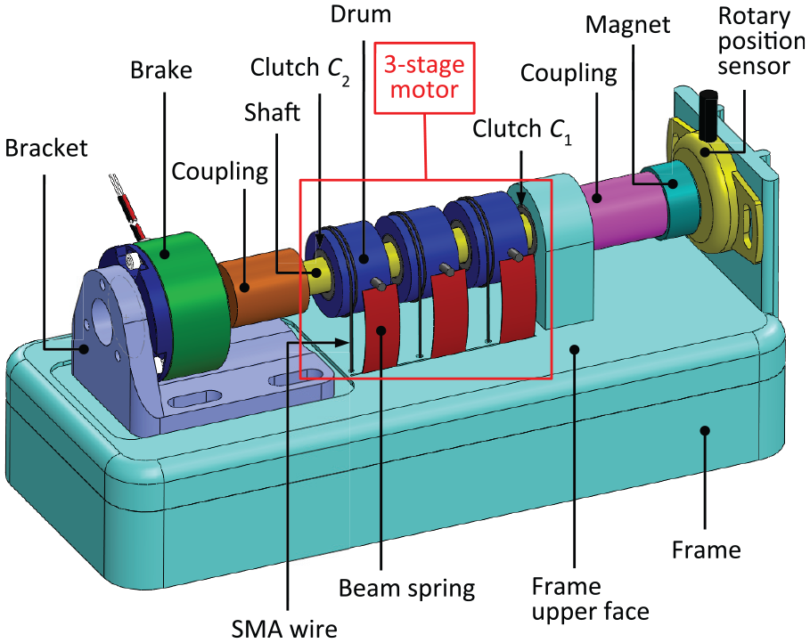
3D CAD model of the prototype motor mounted on the test bed.
The SMA wires of the prototype were powered through a custom electronic board implementing a current-loop control. The desired supply current was set by means of a proportional voltage (gain = 1 A/V) generated by a National Instrument USB 6251 card. The USB 6251 card handled the operation and the data acquisition for the entire system by means of a custom program developed in the LabVIEW environment.
The three SMA wires were electrically connected in parallel. Each wire was supplied through an n-type metal–oxide–semiconductor (N-MOS) field-effect transistor operated in the saturated region and acting as a switch for the corresponding wire. The three transistors were driven by the USB 6251 card through a voltage signal ranging from 0 to 5 V. Despite the parallel hardware connection, the wires were supplied sequentially so as to be activated one at a time.
Design of the unit module
The three basic elements of the unit module in Figure 3 are the wound SMA wire, the overrunning clutch C2 and the backup spring B. As SMA element, the 0.15-mm NiTi SmartFlex wire manufactured by SAES Getters was chosen (Aw = 0.0177 mm2, As = 86°C, Af = 94°C, Ms = 65°C, Mf = 57°C). From the quasi-static martensite and austenite stress–strain curves shown in Figure 9, the following parameters were calculated: Ema = 8 GPa, σg = 35 MPa, s1 = 5.62 and sm = 0.4. Each of the three SMA wires in Figure 8 was wound for 1.5 turns on a 20-mm drum, giving a winding length of about 94 mm. One end of the wire was attached to the drum by means of an electric ferrule inserted into a radial hole in the drum. The other end of the wire was also provided with an electric ferrule and was fastened to the frame by means of a screw. The total length of the wire, including the unwound portion, was about 120 mm.
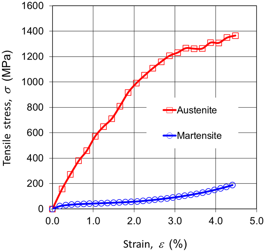
Martensitic and austenitic stress–strain curves for the 0.15-mm SmartFlex® wire used in the prototype motor.
The overrunning clutches for the three unit modules (C2 in Figure 3) and for the support of the shaft (C1) were made using NBS clutches, model HF0812, with a bore of 8 mm, an outside diameter of 12 mm and a width of 12 mm. This particular model of clutches comes without centring roller bearing, which is recommended when the radial loads are particularly high. The friction torque of the clutches, either with or without external load, was not provided by the manufacturer. All four overrunning clutches were coupled by interference fit to a ground aluminium shaft of 8 mm in diameter. Each clutch of type C2 was encased in a polytetrafluoroethylene (PTFE) drum with external radius R = 10 mm.
The three backup springs of the prototype (B in Figure 3) were embodied by axially loaded flat beam springs made by cutting straight laminae from a spring steel sheet. The laminae were inserted vertically into a socket cut into the frame (see Figure 8) and engaged with the corresponding drum through a radial steel pin jutting out from the drum surface. Both ends of the laminae engaged with ‘V’ sockets provided by frame and pin. This solution promoted stability of the contact and reproduced pinned–pinned constraining conditions in the plane of flexure of the beams. The arm of the beam springs with respect to the shaft axis was rb = 10.25 mm. When loaded beyond the buckling limit, the axial beam springs bend transversely at almost constant force (nearly zero stiffness). The combination of relatively large buckling forces with virtually zero post-buckling stiffness makes these elements an ideal backup element for SMA-activated devices. Another practical advantage of this spring solution is the ease with which laminae with the designed mechanical properties can be manufactured inexpensively from steel sheets using simple shears or other standard cutting tools.
Berselli et al. (2014) describe the detailed beam design procedure, which leads to the material, length and cross section of the lamina starting from the required buckling load and total deflection. For the prototype motor, the stress needed to stretch the martensite SMA by εM = 4% is σ0 = σ (ε = εM = 4%) ≈ 155 MPa. The force of the lamina able to generate this stress is P0 = σ0Aw R/rb = 155 × 0.0177 × 10/10.25 ≈ 2.65 N. The overall elongation of the martensitic wire, ΔL, equals the elongation of the wound wire, ΔLm = 3.56 mm, from equation (3) plus the elongation of the free wire, ΔLFree = 0.04 × (120 − 94) = 1.04 mm. This gives ΔL = 4.6 mm, which was rounded up to ΔL = 5 mm. The length, l, of the vertical spring beams, was chosen so that the midpoint of the deflection ΔL = 5 mm was placed approximately at the same height as the motor axis (about 20 mm) from the upper face of the frame (see Figure 8). This condition yielded l ≈ 23 mm.
The prototype laminae were cut from standard high-carbon steel sheets with elastic modulus E = 190.7 GPa, allowable stress σadm ≈ 1400 MPa and thickness ranging from 0.05 to 0.15 mm in steps of 0.05 mm. Entering the above values into the procedure by Berselli et al. (2014) led to a beam spring with free length l = 23 mm, thickness of 0.1 mm and width of 8.46 mm. The actual stiffness of the spring was k0 = 0.061 N/mm, which means that the force increase after the elongation ΔL = 5 mm was about 0.3 N, a mere 11% greater than the nominal force P0 = 2.65 N. Figure 10 shows the force–deflection curve of the single beam spring measured experimentally. The force P0 = 2.65 N (dashed horizontal line) is achieved approximately at midspan of the nominal deflection of 5 mm (hollow circle).
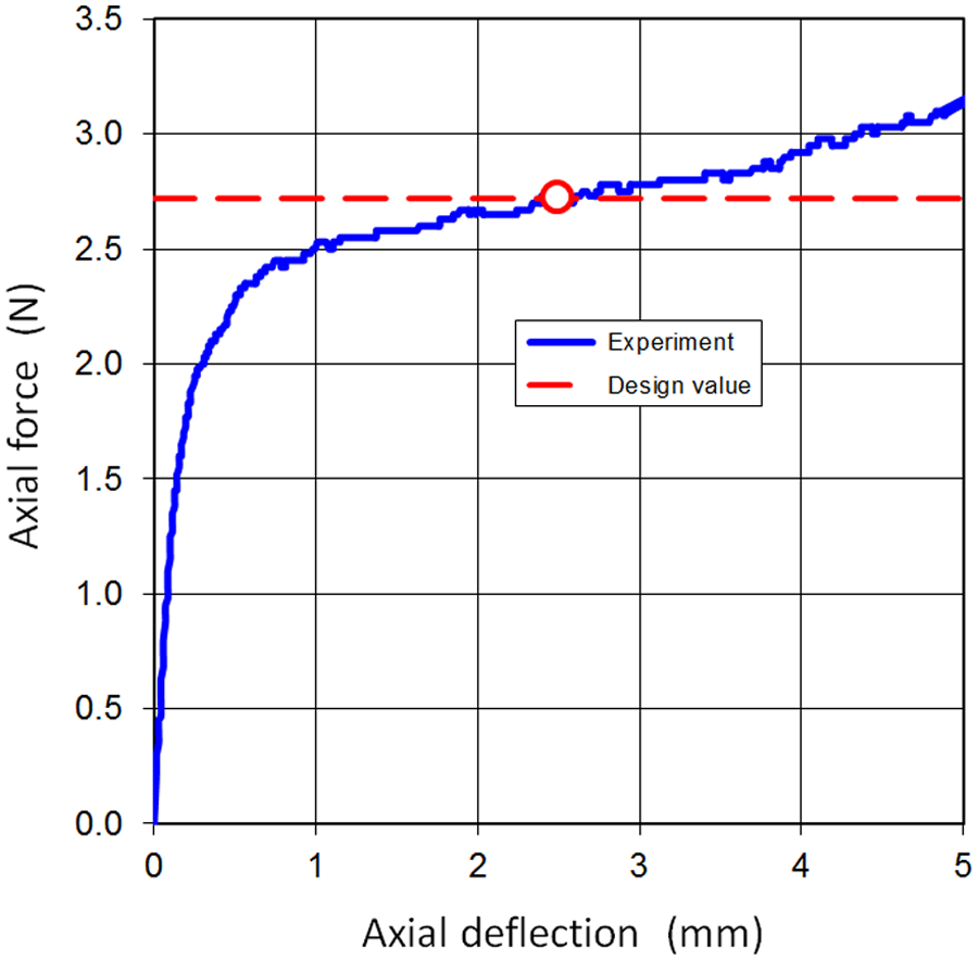
Experimental force–deflection curve for the beam spring used in the prototype motor.
Test bench
The 3D CAD model in Figure 8 includes the sensor and the brake used for experimental characterization. The contactless rotary position sensor (Penny + Giles NRH280DP) is seen on the right, with the stator fixed to the frame and the polarized magnet (rotor) connected to the shaft by means of a polymer joint. The reading of the sensor was acquired by the USB 6251 card and processed by the custom LabVIEW program. At the left end of the frame in Figure 8 is the magnetic hysteresis brake (MOBAC HB3M-2) featuring a two-way torque capacity up to 20 Nmm. The rotor of the brake is connected to the motor shaft while the brake casing is fixed to the frame. Advantages of the magnetic hysteresis technology are the very low-friction torque and the precise linear relationship between applied voltage and braking torque. As for the rotary sensor, also the brake was connected electrically to the USB card and managed logically by the LabVIEW interface.
Prototype testing and model validation
The prototype motor is shown in Figure 11. The drums, beam springs and SMA wires are easily recognizable, together with the rotary sensor and the brake. The frame was manufactured by rapid prototyping using a 3D printer based on fused deposition modelling (FDM) technology. Testing of the prototype in Figure 11 was performed in four stages, with two stages involving the single module and two stages involving the motor as a whole.
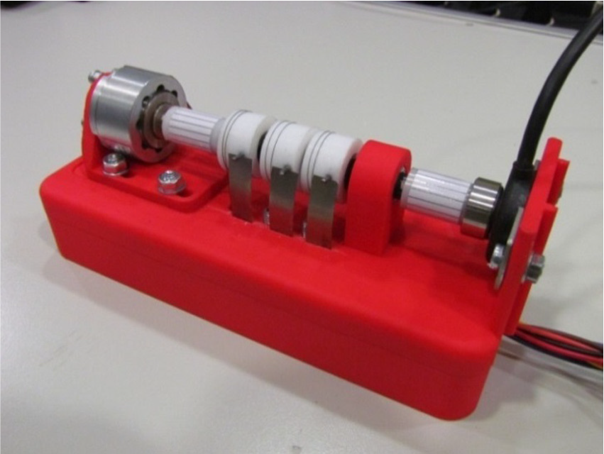
Close-up of the prototype motor in testing arrangement.
In the first test stage, the net stroke of the unit module was measured for five levels of braking torque: 0, 5, 10, 15 and 20 Nmm. The measurements were performed starting with the wire in the martensite state and then supplying the wire with a constant current of 800 mA, which was identified from previous thermomechanical tension tests (Scirè Mammano and Dragoni, 2014a, 2014b, 2015) performed under several stresses on the same SMA wires as used in the motor. This current level corresponds to the minimum supply that transformed completely the martensite to austenite under the stresses generated in the wire by the maximum torque applied to the motor. Of course, lower currents could transform the alloy for lower applied torques. In the real life, the adoption of smart power management to adapt the supply current to the actual applied stress and possibly operate the device with partial transformation would greatly increase the actuation fatigue life (Scirè Mammano and Dragoni, 2015). The experimental points of this first stage of testing are shown in Figure 12 with solid circles and compared with the analytical predictions (hollow squares) for the net rotation defined as

where Δα is the theoretical rotation calculated using the procedure in Figure 6 and ΔαFree is the shaft rotation associated with the strain recovery in the free wire length between frame and drum. Based on the martensite and austenite strains, εM and εA, highlighted in Figure 5, the free rotation ΔαFree can be calculated as
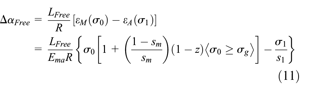
where LFree ≈ 26 mm and the stresses σ0 and σ1 are calculated from equations (1) and (2) with T1 = T2 = 0.
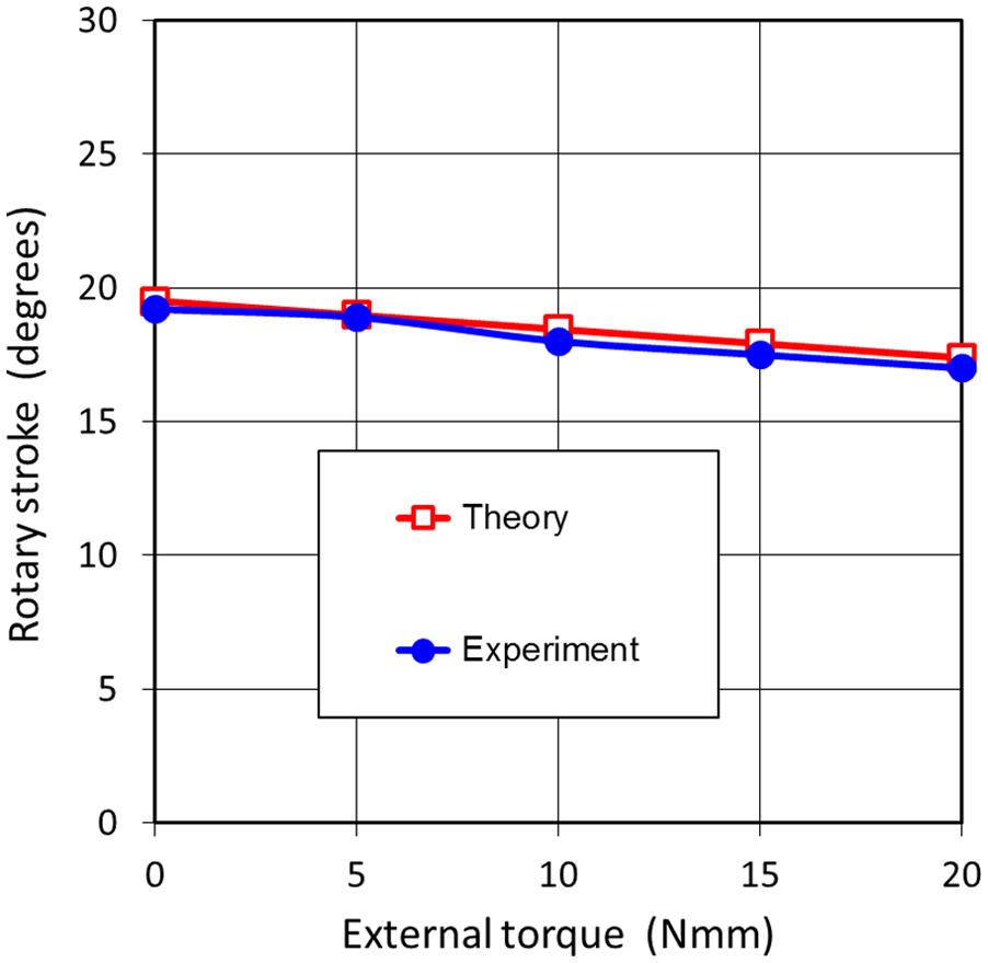
Experimental and analytical output rotation of the unit module as a function of the external torque.
In the second test stage, the transient output rotation of the unit module was measured under five levels of braking torques (0, 5, 10, 15 and 20 Nmm) upon application of a supply current stepping instantly from 0 to 800 mA. The results of this test, which was aimed at quantifying the intrinsic dynamics of the motor, are shown in Figure 13.
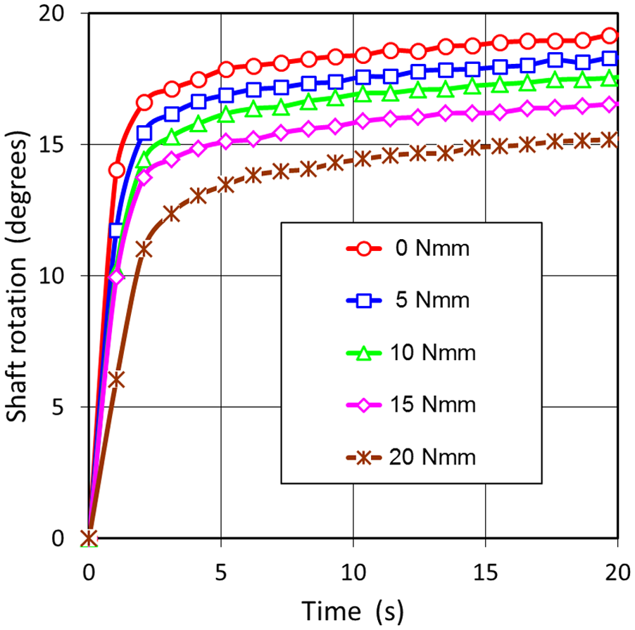
Transient of the shaft rotation (unit module) under a current step of 800 mA for several external torques.
In the third test stage, the mean velocity of the entire motor was measured for several braking torques (again 0, 5, 10, 15 and 20 Nmm) and by varying the supply time, tphase, of the modules. During each single test, a constant current of 800 mA was supplied sequentially to the modules for a time equal to tphase, giving a cooling time equal to 2 tphase before being powered again. The mean angular velocity was calculated as the inverse of the time (in minutes) taken by the motor shaft to perform one complete rotation starting from the condition of all the modules at room temperature (martensite state). The results of these tests are presented in Figure 14.
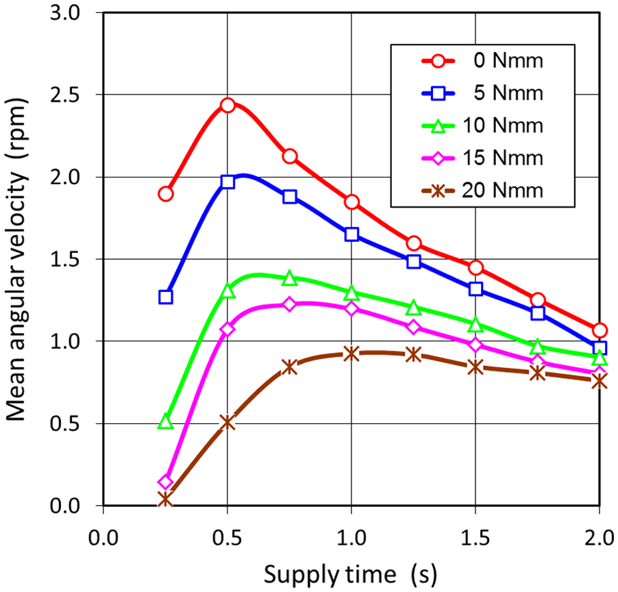
Mean angular velocity of the output shaft (three-stage motor) as a function of the supply time tphase of the modules for several external torques (supply current = 800 mA).
The fourth and final test stage was endurance test, carried out with the chief aim to investigate the fatigue life of the SMA wires in the actual working conditions of the motor. The modules were actuated sequentially with the following test parameters: supply current = 900 mA, supply time tphase = 1.0 s, cooling time = 2.0 s and external torque TL = 10 Nmm (implying a maximum wire stress of 227 MPa). The results of the endurance tests are shown in Figure 15 for two runs performed on two distinct sets of wires. The rotation reported along the vertical axis in Figure 15 represents the overall rotation of the shaft upon completion of an entire supply cycle (all three stages have been activated and deactivated).
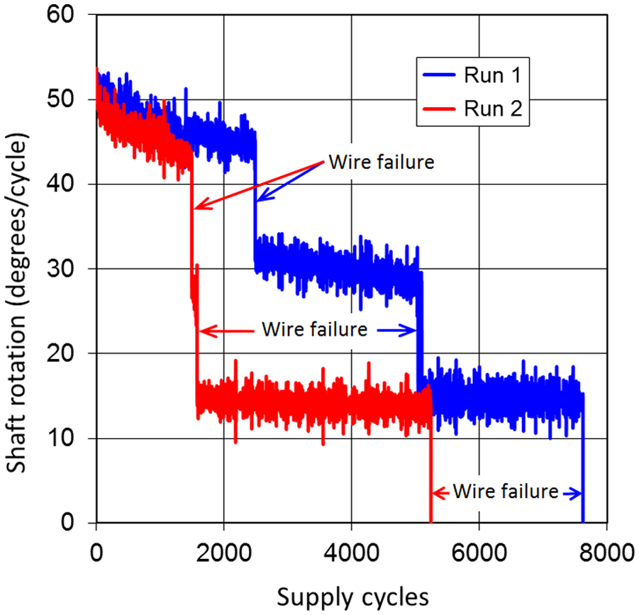
Endurance test results for the three-stage motor under an externally applied torque TR = 10 N mm (the red and blue curves refer to two different sets of SMA wires).
Discussion
From an engineering standpoint, the main advantage of the design presented is the modularity of the concept. The assembly of any number of unit modules (overrunning clutch, SMA wire and backup spring) on the same shaft, as shown in Figures 4, 8 and 11, can easily lead to series, parallel or series-parallel working modes by choosing the proper scheme of electrical power management. Sequential supply of the modules (series mode) improves the regularity of the motion (e.g. the initial stroke of 52°–53° in Figure 15 for the serially supplied three-stage motor in Figure 5 is about three times the 18° stroke of the unit module in Figure 12 for the same applied torque TR = 10 Nmm). Simultaneous supply (parallel mode) increases the output torque (e.g. parallel supply of two modules would maintain the same characteristic curves of stroke/rotation/velocity plotted in Figures 12 to 14 when the external torques are exactly doubled). Overlapping of the supply times between modules (series-parallel mode) enhances both regularity and output torque.
Another asset of the construction is represented by the particular type of backup spring used to recoil the SMA wire upon deactivation of the modules. Besides being compact, the flat beam springs provide remarkable deflections at nearly constant force. Figure 10 shows that the variation of the actual force is within ±15% of the nominal force (red dashed line) in the range of deflections 0.5−5 mm. Furthermore, the flat beams are easily manufactured to any design, a production flexibility which is particularly important for prototype or custom constructions.
The good uniformity of the force generated by the backup spring made it possible to use the analytical model developed by Scirè Mammano and Dragoni (2011b) to describe the torque–stroke behaviour of the unit module (see also Figure 7). Figure 12 shows that, although the restoring force of the backup spring is not precisely constant as assumed by Scirè Mammano and Dragoni (2011b), the analytical predictions (hollow squares) fit very closely the experimental data (solid circles). The error between theory and experiment is never greater than 2.5% for all the torques applied to the module. It is seen that the analytical predictions are always in excess of the test data. This is probably due to having dropped from the model the friction torque in the clutches (C1 and C2 in Figures 3 and 8) because this piece of information was not available from the supplier.
The dynamics of the unit module emerging from Figure 13 (transient rotations following a stepped current supply) can be considered satisfactory. The time needed to achieve 50% of the full stroke (values in Figure 12) ranges from 0.7 to 1.3 s as the external torque increases from 0 to 20 Nmm. These promising response times can probably be further reduced by increasing the supply current or adopting optimized supply schemes. For example, pulse-width modulation (PWM) supply is becoming more and more popular in the field of SMA actuation (Hannen et al., 2012) because it increases the heating efficiency without impairing the fatigue life of the material (Scirè Mammano and Dragoni, 2015).
The relevance of the supply scheme on the dynamic behaviour of the motor as a whole is clearly visible also in Figure 14. The key variable in Figure 14 is the supply time (tphase) of each module within a sequential supply scheme across the modules. Due to the sequential activation, the heating time of the single module affects also the cooling time of the same module, which equals the time needed to supply the remainders (for the present case of three modules, the cooling time is 2 tphase). Figure 14 shows that, regardless of the applied torque, the mean velocity of the motor initially increases and then decreases with the supply time. For very short supply time, the wire has not enough time (2 tphase) to cool down and recover the strain before the next supply cycle starts again. For relatively longer supply times, the modules remain idle even after they have cooled down and the strain in the wire has been completely recovered. The curves in Figure 14 show that the peak angular velocity decreases with the applied torque while the supply time needed to achieve the peaks increases with the torque. Both results are coherent with Figure 13 (lesser strokes and longer transient times for larger torques) and are explained by the increase in the transformation temperature of the SMA promoted by the higher stresses in the wire. Since the supply current was always the same (800 mA), the higher transformation temperatures require more time for complete transformation, leading to poorer dynamics for the higher loads.
The cycles to failure of the wires during cyclic operation of the motor (Figure 15) range from about 1500 to about 7500, with an overall mean of about 3900 cycles. The applied stress during the activation of each motor stage was almost constant, ranging from 227 to 234 MPa. During deactivation, the only force applied to the wire was due to the beam spring, which was designed for inducing a martensite strain of 4%. For a similar combination of applied stress and maximum martensite strain (235 MPa and 4%, respectively), the laboratory tests by Scirè Mammano and Dragoni (2014, 2015) gave an average life of about 7900 cycles (with a standard deviation of 965 cycles). The lower fatigue life with respect to published data (Scirè Mammano and Dragoni, 2014a, 2014b, 2015) is presumably due to the bending overstresses consequent upon winding of the SMA wires on the drum. This drawback could be reduced using many thinner wires on each drum instead of a single thick wire. This solution would conserve the area of the wire cross section (thus preserving the output torque) while reducing the bending stresses due to the lesser ratio of wire diameter to drum diameter.
Another drawback of the wire-on-drum solution, already reported by Scirè Mammano and Dragoni (2011b) with possible detrimental effects on the fatigue life, is the steady increase in the temperature of the PTFE drum during cyclic activation of the wire. This is because the low-friction drum material has also a relatively low thermal conductivity. A possible solution to this problem could be limiting to a minimum the thickness of the PTFE ring covering the overrunning clutch. Better still, using modern coating techniques (Incerti et al., 2011), the outer ring of the clutch could be cladded with a thin layer of antifriction material to let the metal body of the clutch function as a heat sink. In this way, the heat would be taken away from the wire through the metal-to-metal contact between clutch, shaft and eventually the frame of the motor.
The prototype motor was tested under externally applied torques up to 20 Nmm because this was the maximum torque capacity of the available brake. For the torque of 20 Nmm, the stress in the SMA wire averages 260 MPa through the activation cycle. Although this stress level is not low, this particular alloy could certainly withstand higher stresses, resulting in higher output torques. This, of course, would be achieved for ever-decreasing rotary strokes, mean angular velocities and useful fatigue life.
The overall dimensions of the prototype in Figure 11 are L × W × H = 168 mm × 70 mm × 65 mm, inclusive of frame, brake and position sensor. By excluding brake and sensor (which belong to the test apparatus) and optimizing the frame, the net dimensions of the present system could be easily reduced to 60 mm × 20 mm × 35 mm, for a total volume V = 42,000 mm3. With reference to the parameters defined in the comprehensive comparison by Nespoli et al. (2010), this reduced motor would present the following properties: specific angular stroke, SR ≡ (angular stroke)/(volume)=360°/42,000 =0.0086°/mm3; specific output torque, TR ≡ (maximum output torque)/(volume) = 20/42,000 = 0.48 ×10⁻³ Nmm/mm3; and specific work per cycle, WR ≡ (work per cycle)/(volume) = 20 × 10−3·2π/42,000=0.3×10−5 J/mm3, which place this solution in the high end of all actuators known so far. In particular, the specific output work per cycle, WR, is about three times the highest value reported by Nespoli et al. (2010).
In general design terms, the output torque of each stage is proportional to the stress in the wire times the wire cross section times the drum radius. Given the characteristic axial stresses σ0 and σ1 of the material (Figure 5), the output torque of each stage is proportional to the square of the wire diameter times the drum radius R. As a result, if the ratio of wire diameter to drum diameter is fixed to limit the bending overstresses in the wire, the output torque of the unit stage is proportional to the third power of drum radius R. As observed above, using multiple wires per drum would increase the torque output for given radial size with minimum impact on the longitudinal size of the module. In terms of stroke for given torque, from equations (6) to (9), we see that the characteristic angles contributing to the net rotation Δα do not contain the drum radius. Thus, given the characteristic stresses of the material (σ0 and σ1), the stroke of the unit stage is independent of the size of the drum.
Conclusion
A three-stage rotary motor combining SMA wires wound on low-friction drums coupled to a common centre shaft through overrunning clutches has been modelled, manufactured and tested. The multi-stage concept allows the motor to be driven electrically in series (to improve the velocity), in parallel (to improve the output torque) or in series-parallel (to improve both velocity and torque) with no changes to the mechanical hardware. A previously developed analytical model for the wire-on-drum system is adapted to describe the behaviour of the single module and is found to fit well with the measured performance in terms of applied torque and net stroke. Thanks to the unidirectional coupling offered by the overrunning clutches, the motor can run indefinitely with no limits on the magnitude of the shaft rotation. The three-stage prototype tested presents specific strokes, specific output torque and, above all, specific output work per cycle which place the device in the upper end of performance reported for SMA actuators and motors. Preliminary endurance tests on the motor indicate a fatigue life of the wires ranging from 1500 to 7500 cycles under stresses of about 260 MPa. Although these values are lower than reported for straight wires under similar stress levels, the performance of the device can be optimized by proper selection of the ratio between wire diameter and drum diameter.
Footnotes
Appendix 1
Acknowledgements
This paper was presented at the ASME 2014 Conference on Smart Materials, Adaptive Structures and Intelligent Systems – SMASIS 2014, 8–10 September 2014, Newport, RI, USA (Paper number SMASIS2014-7406).
Declaration of Conflicting Interests
The author(s) declared no potential conflicts of interest with respect to the research, authorship and/or publication of this article.
Funding
The author(s) disclosed receipt of the following financial support for the research, authorship, and/or publication of this article: This research was partially funded by the Office for Industrial Development of Italy’s Regione Emilia Romagna (grant Intermech 2010).