
Abstract
Atherosclerosis is one of the major types of cardiovascular diseases. Stent deployment into the stenosed artery is the most common treatment for atherosclerosis. Two common stent models based on two different expansion principles are balloon-expandable and self-expandable stents. Depending on the modality of the expansion, the material used for these two stents varies. Despite the extensive progress made in the field of stent construction, plaque fragmentation and in-stent restenosis are two of the problems that still cause complications in stenting. Computational modeling and finite element method help us predict the damage effects to the artery and plaque in the stenting process. In this article, we simulate the insertion of two stents (the stainless steel stent and the shape memory alloy stent) in a diseased artery with real geometry. Results are compared to account for the effects of these stents on the artery, especially, the maximum stress in the plaque and arterial layers and surgically induced damage as the main cause of plaque fracture during the stent deployment and in-stent restenosis. It is found that arising from superelasticity, the shape memory alloy stent induces less damage to the artery. In addition, the stress created in the artery by the shape memory alloy stent is smaller. Therefore, the risk of plaque fragmentation and in-stent restenosis is reduced in shape memory alloy stents.
1. Introduction
Atherosclerosis is one of the cardiovascular diseases in which some components of the blood (excessive fat, cholesterol, and calcium) deposit in the artery, called plaque, cause partial or total occlusion of the artery. One way to treat atherosclerosis involves the deformation of plaque taking advantage of stenting. Despite the fact that the insertion of the stent in the artery has long been put to use, it still faces some complications, such as plaque fragmentation and in-stent restenosis (ISR). After the insertion, over time, a thin layer of cells grows over the stent. When the growth of this layer continues, it may lead to restenosis. Indeed, neointimal hyperplasia after stent deployment causes significant restenosis (Migliavacca et al., 2004). Different methods were proposed to prevent or lower the rate of restenosis such as intravascular brachytherapy and stent-based drug delivery. Stent design and mechanical properties have a direct effect on the amount of ISR by affecting the value of the stent-induced damage in arterial tissue, as the main cause of neointimal hyperplasia (Holzapfel and Fereidoonnezhad, 2017).
Two common types of stents for this purpose are (1) balloon-expandable stent and (2) self-expandable stent. Inserting the stent in the artery and expanding, the artery and plaque are pushed and extend the amount of blood flow. These two types are commercial stents based on two different expansion principles.
The balloon-expandable stent is positioned by inflating the balloon. The balloon inflates, and the stent expands under the pressure of the balloon. One of the common materials for a balloon-expandable stent is stainless steel (SS). A self-expandable stent is compressed by a protective sheath after being manufactured. In the stenosis artery, when the sheath is retracted, the stent expands by itself.
Smart materials, for example, shape memory polymers (SMPs) and shape memory alloys (SMAs) are good candidates for the fabrication of artery stents. A number of models have been presented to explain shape and force recovery response of SMPs (Baghani et al., 2012b, 2014) for use in smart polymeric stents. Some researchers examined this material in different loading conditions by numerical or analytical methods for potential use in cardiovascular applications (Ansari et al., 2018; Baghani et al., 2012a). They also studied different methods to improve their performance (Yarali et al., 2019). However, much attention has been paid to SMAs for use in stents due to their pseudo-elastic properties. The SMA pseudo-elasticity of self-expandable stents offers some advantages over the balloon-expandable ones, that is, a more flexible delivery system, a lower risk to overstretch the artery during expansion, lower bending stresses when deployed in the artery (Carter et al., 1998). Moreover, SMA seems to have better biocompatibility and corrosion resistance than SS (Thierry et al., 2002).
Different constitutive models have been provided to explain the behavior of SMA material (Auricchio and Taylor, 1997; Brinson and Lammering, 1993; Souza et al., 1998) and improved over time (Auricchio et al., 2007; Poorasadion et al., 2014). These models take into account the superelastic and shape memory effects of SMA materials by considering martensite and austenite phase transformation. Some studies developed numerical tools for SMA materials according to the proposed constitutive models (Gu et al., 2016).
Different reports are presented to examine the stent insertion into the artery. In some works, the effects of the SMA stenting were investigated (Nematzadeh and Sadrnezhaad, 2013; Wall et al., 2010; Wu et al., 2007a; Zhao et al., 2012). In some other papers, the effects of SS stent were surveyed (De Beule et al., 2008; Douglas et al., 2014; Karimi et al., 2014b). A few works examined the difference between SMA and SS stents in arteries experimentally and computationally (Aboodi et al., 2014; Migliavacca et al., 2004). Such papers investigate the influence of the mechanical behavior of SMA on their effects on the artery in stenting process. Arising from the pulsed blood flow, the issue of fatigue in the stent is vital; thus, some researchers scrutinized fatigue of SMAs and stents (Moumni et al., 2005; Pelton et al., 2007; Scalet et al., 2018). The modeling of the geometry and mechanical behavior of the artery and the plaque are important issues to predict the accurate effects of the stent on the artery. The geometry and mechanical behavior of the artery vary from one patient to another, and with the formation of the plaque, this difference becomes even more significant. However, in different studies, different assumptions were applied for modeling of the artery to simplify the whole process. Majority of studies employed a simplified cylindrical shape for artery (Bukala et al., 2016; Karimi et al., 2014a; Lally et al., 2005; Suyitno et al., 2018; Takashima et al., 2007; Teo et al., 2000; Wu et al., 2007b; Xu et al., 2016; Zahedmanesh and Lally, 2009) which does not seem to be a realistic assumption. Some recent studies focused on a more real geometry of the stenosed artery (Holzapfel et al., 2005; Wall et al., 2010). However, they employed a hyperelastic constitutive model for the arterial tissue, which is not authentic enough for supra-physiological loading occurring during the stent deployment. Stenting may cause some inelastic phenomena such as stress softening (Mullins effects) and permanent deformation in the artery where hyperelastic models are not capable of predicting. Therefore, some researchers proposed models to predict the injury in the artery (Fereidoonnezhad et al., 2016; Maher et al., 2012).
In this article, it is aimed to compare the effects of the SMA and SS stents on real geometry artery by considering a hyperelastic model with stress softening and permanent deformation behavior to simulate the mechanical behavior of the artery. Knowing the extent of the damage enables us to predict the long-term effects as well as the short-term ones. Stent developers must make sure the quality of the stent before its application inside the body. Testing the expansion of the stent in the real condition is not possible. Therefore, computational analysis opens a new avenue for analyzing the stent before its manufacturing and deployment.
This article is organized as follows: In Section 2, we discuss the steps of simulations such as the introduction of the geometry and material models of the stents, artery, and plaque; meshing; boundary conditions; and loading. In Section 3, the results of the simulations and explanations are presented. Finally, we present a summary and draw some conclusions in Section 4.
2. Materials and methods
The requirements for computational simulations such as the geometry of the stent and stenosis artery, mechanical behavior of the stent and artery, the stent–artery interaction, the boundary conditions, and loading are described in detail in the following.
2.1. Material models
In the following, the constitutive equations to describe the mechanical behavior of two stents (SMAs and SS), plaque, and artery are briefly introduced.
2.1.1. Artery and plaque
The constitutive model proposed in Fereidoonnezhad et al. (2016) is employed for the arterial layers. This model is an inelastic model, which considers the hyperelasticity, stress softening, and permanent deformation behaviors of the artery. It is also able to evaluate the damage in the arterial tissue after the stent insertion. In the following, this model is briefly discussed (Fereidoonnezhad et al., 2016).
In this model, the local deformation is split into volumetric and isochoric part. Therefore, the deformation gradient is considered as

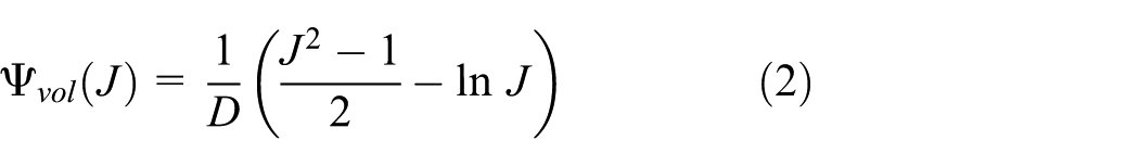
where
where


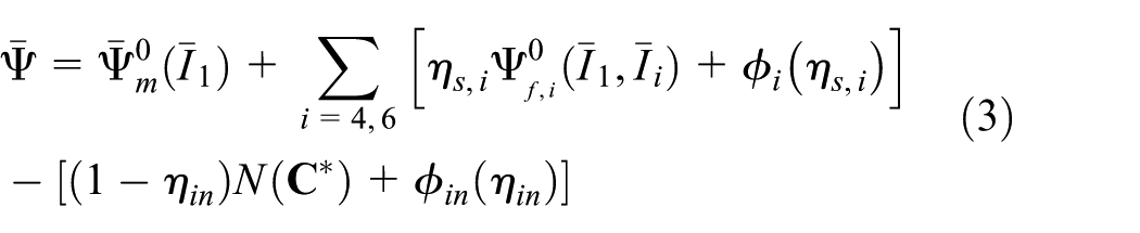
The stored strain energy function in the ground matrix

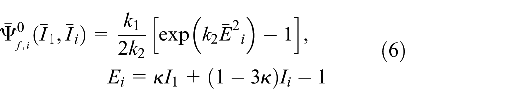
in which
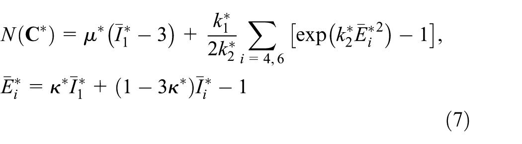
where
Material parameters of the artery layers and plaque are listed in Table 1. It should be noted that the dissipation and damage effects in the plaque are disregarded. Therefore, the constitutive model of plaque confirms to Gasser et al. (2006). To identify the material parameters of the plaque, experimental data from Holzapfel et al. (2004) are borrowed to calibrate the material parameters by the optimization toolbox in MATLAB; the fitting diagram of experimental data is plotted in Figure 1.
Material parameters of the hyperelastic -damage (inelastic) model for layers of the artery (Fereidoonnezhad et al., 2016) and hyperelastic model of the plaque (Holzapfel et al., 2004).
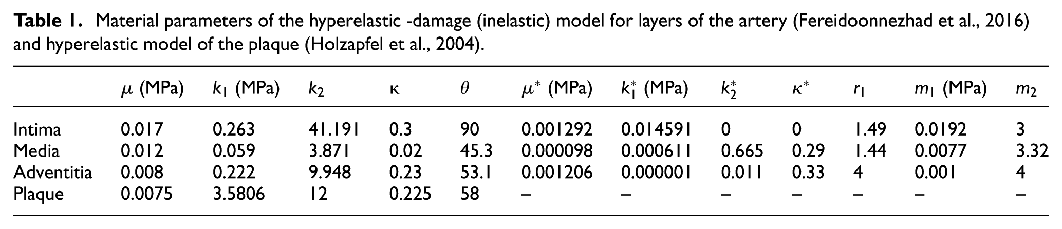
The fitting diagram of the plaque experimental data and model to identify the material parameters of the plaque.
2.1.2. Stent
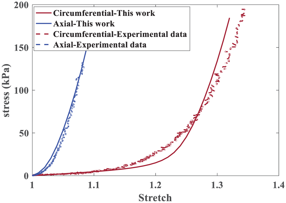
The problem is considered for two different stents (balloon-expandable and self-expandable). The typical material for the balloon-expandable and self-expandable stent is SS316LN and Nitinol SMA, respectively. Material parameters for SS316LN stent are borrowed from Auricchio et al. (2001) which includes the elastic and plastic behavior of the stent (see Table 2).
Material parameters of stainless steel stent.
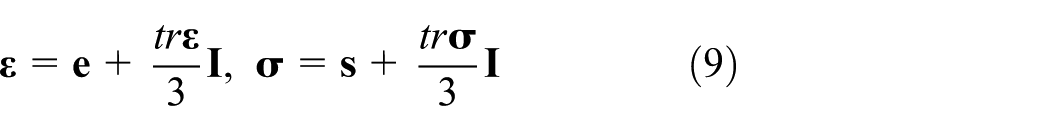
The self-expandable stent has the pseudo-elastic behavior. Due to this property, the SMA stent is capable of recovering its original shape when it is unloaded after a considerable amount of strain (as shown in Figure 1). The constitutive mechanical behavior of SMA is based on the Souza model introduced in Souza et al. (1998) and Auricchio and Petrini (2002). In this model, the strain and stress are decomposed into deviatoric and volumetric parts
where
in which

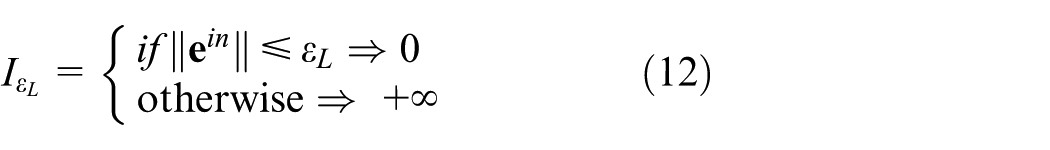
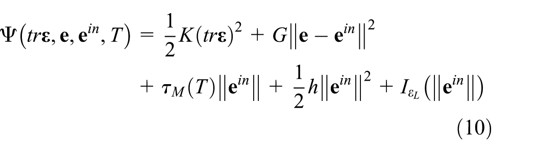
A UMAT is implemented in ABAQUS to implement this SMA constitutive model in an implicit time-discrete form. Material parameters of SMA listed in Table 3 are borrowed from Auricchio et al. (2010) and superelastic response of SMA materials is presented in Figure 2.
Material parameters of SMA stent (Auricchio et al., 2010).
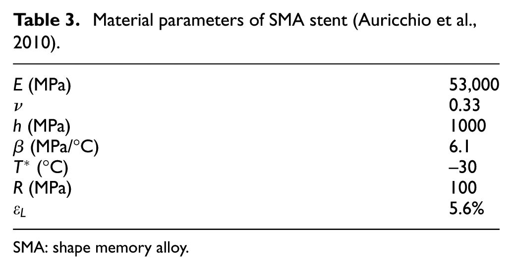
SMA: shape memory alloy.
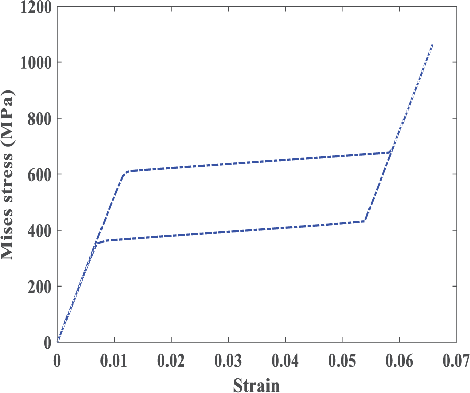
Stress–strain diagram shows superelastic behavior of SMA materials in the loading and unloading process.
2.2. Model geometry
In this study, we look into the individual human stenosis as presented in Holzapfel et al. (2005). Therein, the model geometry of the stenosis artery is composed of different layers and is almost 34% clogged specified from high-resolution magnetic resonance images (hrMRI) and reconstructed through non-uniform rational B-splines (NURBS). As shown in Figure 3, a high degree of non-symmetric stenosis is observed in the artery, in contrary to the symmetric assumption used in the majority of the previous studies (Bukala et al., 2016; Karimi et al., 2014a; Lally et al., 2005; Takashima et al., 2007; Zahedmanesh and Lally, 2009).

The geometry of the stenosis artery. The tissue components are adventitia , media  , intima
  , and plaque
  .
.
Two types of commercial stent commonly employed in the treatment of the artery stenosis are the balloon-expandable stent and the self-expandable one. To compare the effects of different materials on the stent performance, it is important to avoid the influence of geometrical effects on the results. Therefore, the geometry of the SMA stent is assumed to be similar to the deformed configuration of the SS stent. The inner and outer diameters of the SS stent and the inner and outer diameter of the SMA stent are 2, 2.1, 5, and 5.1 mm, respectively. Strut width in both stents is 0.1 mm. Two stents are illustrated in Figure 4.
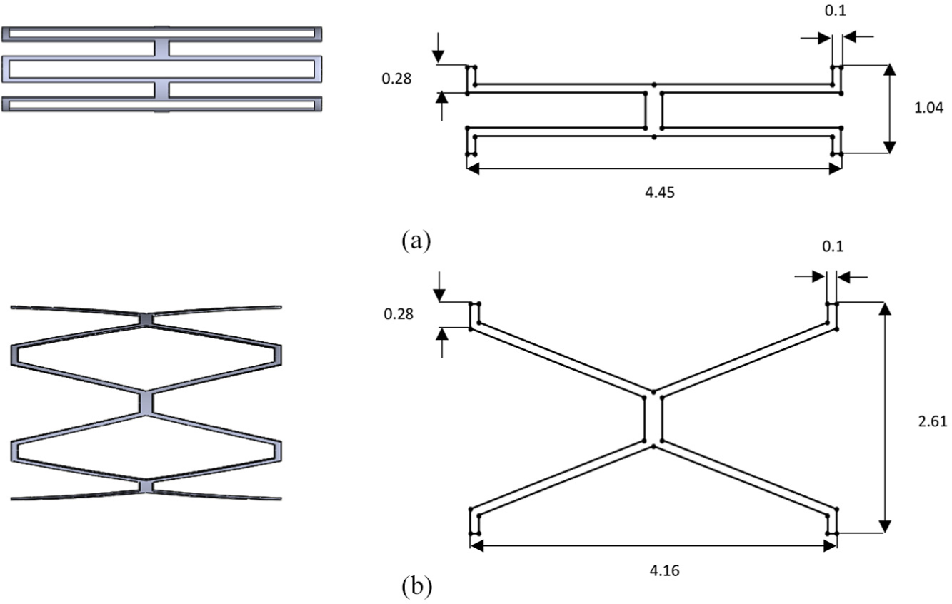
The geometry of the (a) SS stent and (b) SMA stent. Figures in the right are one-fourth of stents.
2.3. Loading and boundary conditions
Self-expandable stents should be compressed at first; thus, the stent with diameter of 5 mm is squeezed to the diameter of 2 mm. After removing the applied pressure, the stent expands to its original shape. For the balloon-expandable stent, it needs to be expanded. For this purpose, a radial displacement is applied directly to the stent. At first, the diameter of the balloon-expandable stent is 2 mm, and after expansion, it reaches to 5 mm. Finally, both stents are removed for further study of the residual stress and induced-damage distribution in the arterial tissue (unloading process). When the stent (balloon-expandable or self-expandable) contacts the plaque and the artery, the interaction between them leads to the expansion of both the plaque and artery. The contact between the outer surface of the stent and the inner surface of the plaque and artery is assumed to be frictionless. For both stents, two ends of stents are constrained in the circumferential direction. To avoid moving the stent in the longitudinal direction, the stent is constrained at one end in the longitudinal direction. Both ends of the artery are constrained in the longitudinal and circumferential directions while the radial displacement is permitted.
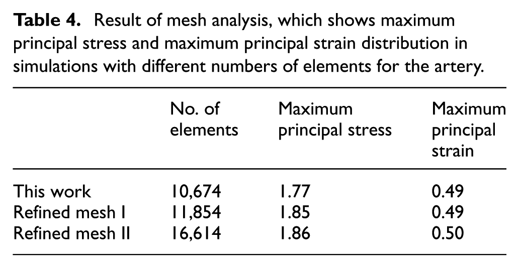
2.4 Mesh independency study
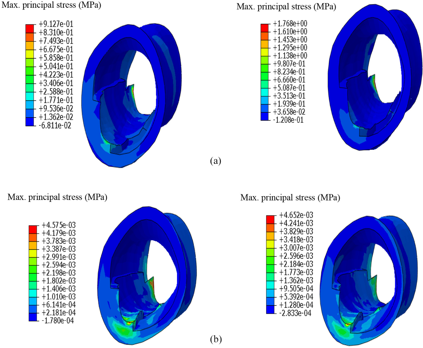
The total number of 7020, 2606, and 3654 elements is used for artery, self-expandable stent, and balloon-expandable stent, respectively. Three-dimensional eight-node linear, hybrid elements (C3D8H) are put to use for artery and plaque, and three-dimensional eight-node linear elements (C3D8) are assigned to the stents. According to the mesh analysis test, these elements are suitable candidates for models because it supplies a good balance between the accuracy and computational cost. To check the mesh convergence, the analysis is performed with a refined mesh for the artery. The results of the balloon-expandable stent implantation in the artery after the loading process are shown in Table 4, which indicates the mesh-independent result.
Result of mesh analysis, which shows maximum principal stress and maximum principal strain distribution in simulations with different numbers of elements for the artery.
3. Results and discussions
In this section, the effect of using two different types of stent on the artery is examined. As depicted in Figure 5, at the loading step, the maximum principal stress induced by the SS stent in the artery is almost twice the maximum principal stress induced by the SMA stent. After unloading, the maximum principal stress developed by SS stent is still 10% higher than that of the SMA stent.
Distribution of the maximum principal stress after (a) loading (expansion of the stent) and (b) unloading. In the left are results of the simulation with the SMA stent and in the right are those of SS stent.
It is observed that by both stents, the pattern of the maximum principal stress and the place where it is the highest in the artery is almost similar (as depicted in Figure 5). One may conclude that the location of the maximum stress depends highly on the geometry of the artery as well as the position of the stent in the artery; it is noteworthy that this feature cannot be captured in a symmetrical artery as was assumed in most of the previous studies (Bukala et al., 2016; Karimi et al., 2014a; Lally et al., 2005; Takashima et al., 2007; Zahedmanesh and Lally, 2009). Knowing the critical position helps us predict the restenosis state and provide solutions to this problem. It should be noted that after unloading, the maximum residual stress does not occur at the same position as the maximum stress in loading (compare Figure 5(a) and (b)); this effect can be due to the geometry of the artery.
At the loading stage, there is 10% difference between the strain caused by the SS and SMA stent, and the unloading strain is higher in the artery by SS stent that shows much permanent deformation by SS stent. This residual strain can affect the subsequent behavior of the artery and it may cause some dysfunctions in the artery. As stated in the previous section, the position of the maximum strain is not the same after the loading and unloading (see Figure 6(a) and (b)). Moreover, the contact pressure of the SS stent is 30% higher than that of the SMA stent (see Figure 6(c)).
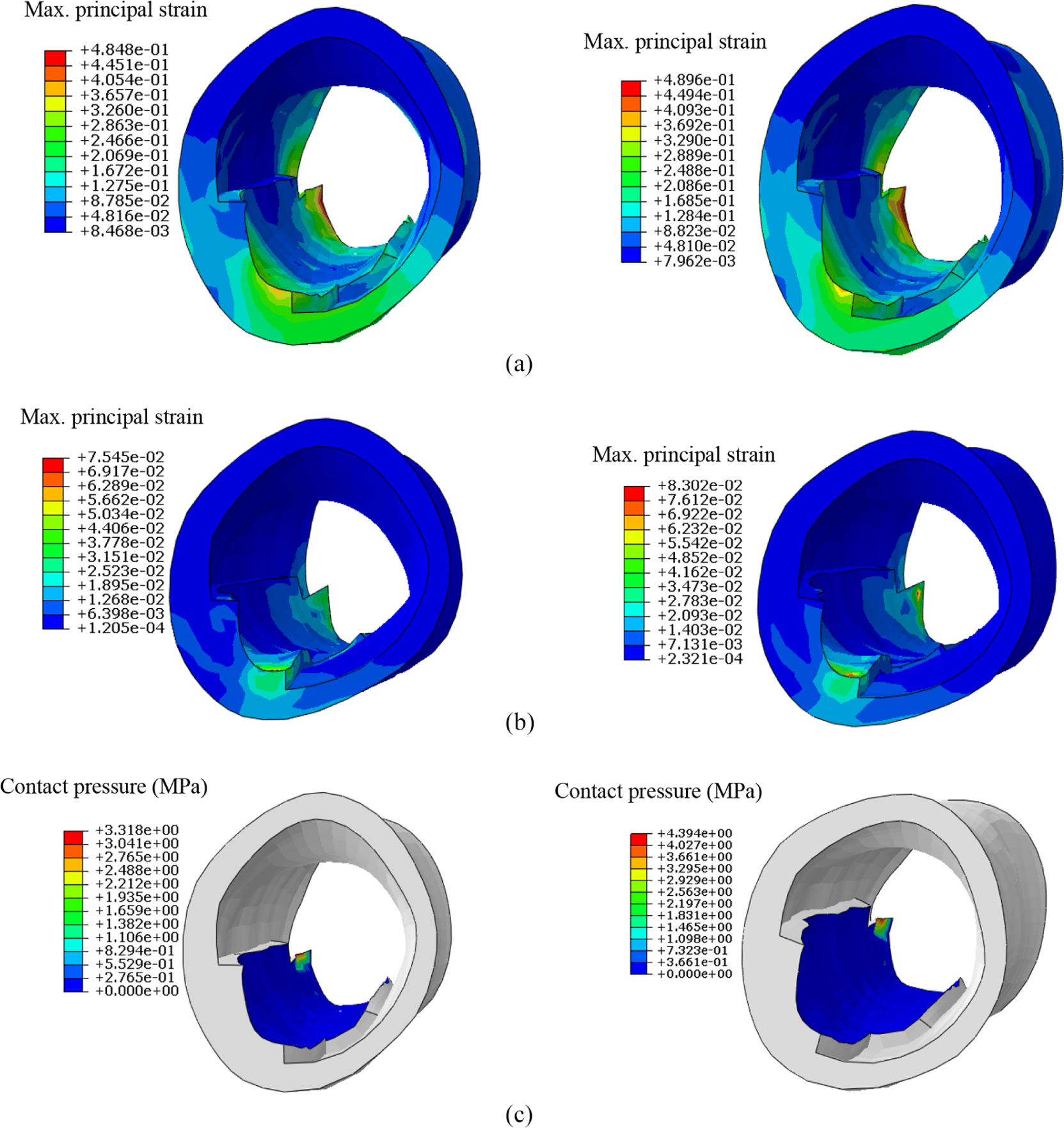
Distribution of (a) strain after loading (expansion of the stent), (b) strain after the unloading, and (c) contact pressure. In the left are results of the model with the SMA stent and in the right are those of the SS stent.
Maximum damage developed in the artery by each stent is plotted in Figure 7. As shown, with a similar displacement of stents, the damage is higher in SS stenting. The highest damage takes place in intima for both simulations. As explained, the damage in arterial tissue is known as the main mechanical stimulus for ISR and influences the long-term behavior of the artery. Consequently, prediction of the surgically induced damage is vital for the evaluation of the long-term success of the procedure.
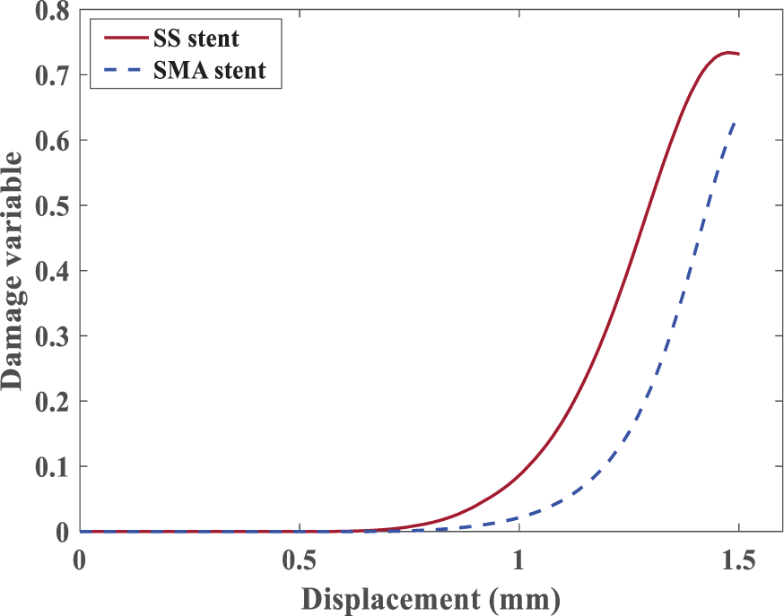
Distribution of the damage for SS and SMA stents.
In Figure 8, distribution of the stress has been shown. The generated stresses by SMA stent on the plaque are smaller than those of SS stent. Given presented results, in the same conditions, the SMA stenting resulted in more desired outcomes than the SS stent, namely, less damage and stresses.
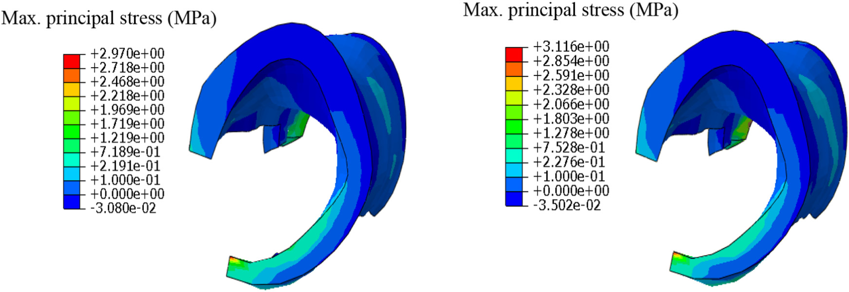
Distribution of the maximum principal stress. In the left is the result of the model with the SMA stent and in the right is the result of the model with SS stent.
In Figure 9, stress–strain diagram of four different nodes of the SMA stent in the crimping and expanding process is plotted. As one may observe the superelastic behavior of the SMA causes the structure to undergo larger strains while the stress does not need to go much higher. This phenomenon lowers the stresses applied to the vessel walls, which means less damage. This is the key idea in putting to use SMA in stents instead of conventional metals, that is, SS.
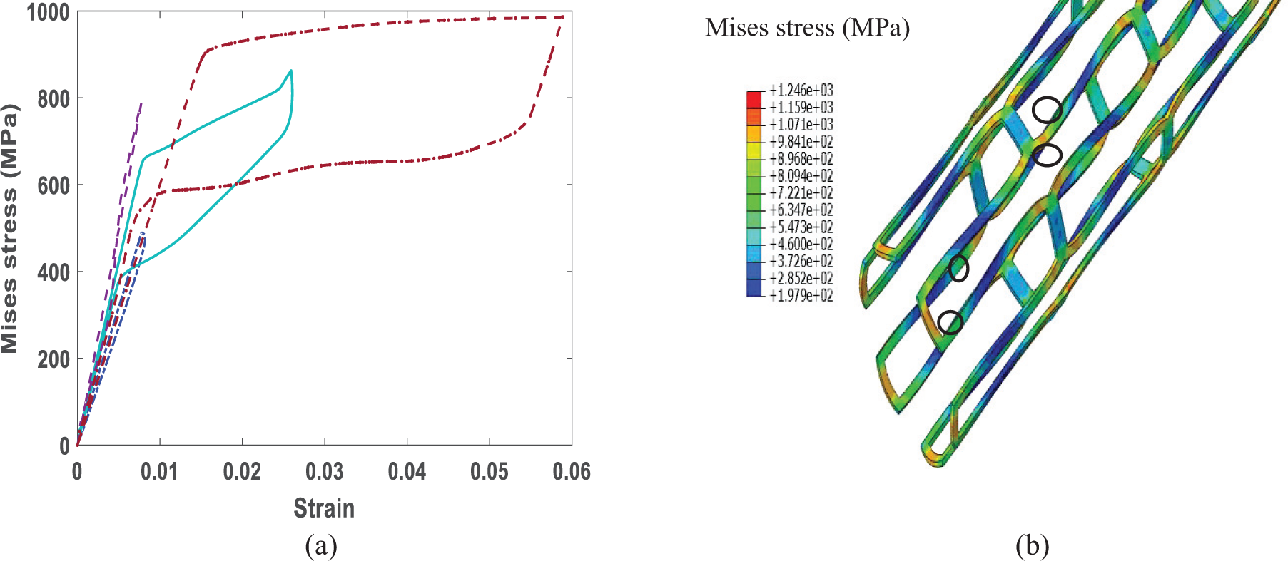
(a) Stress–strain diagram of four nodes, which are determined in (b), of the SMA stent in the crimping and expanding process.
To expand SS stent, pressure is necessary which is applied with a balloon in practice. In Figure 10, the diagram of pressure–displacement is plotted. This pressure is applied to the artery, and due to its behavior, the artery encounters higher stresses and damage in comparison to the artery opened by the SMA stent.
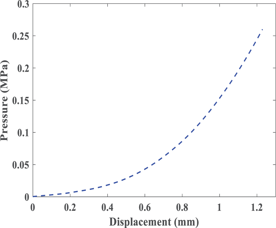
Pressure–displacement diagram of balloon-expandable stenting.
4. Summary and conclusion
The insertion of a stent in the artery is one of the most common remedies for atherosclerosis. Two common types of stents are balloon-expandable and self-expandable stent. Despite the significant benefits of this treatment method, there are some short-term consequences, for example, plaque fragmentation, and long-term consequences, for example, ISR for patients; in this article, we studied the damage in the artery and the stress in the plaque. This damage growth can potentially lead to plaque fragmentation. Here, the stent type is a major factor.
Most of the previous models were based on the simplified symmetrical artery and commonly one type of stent. Moreover, models, which considered the patient-specific geometry of the stenosed artery, at best have considered a hyperelastic constitutive model for the arterial tissue, which is not enough for supra-physiological loading during stent insertion. To the best of the authors’ knowledge, a comparison between two types of smart and common stents has not been performed under these circumstances (the patient-specific geometry of the stenosed artery and employing an inelastic model to investigate damage development in the artery). In this article, to compare the effect of insertion of SMA (due to its pseudo-elastic behavior) and SS stent, we simulated the insertion of the stent in an artery with real diseased geometry, while inelastic arterial behavior due to the supra-physiological loading was accounted for. Considering both patient-specific geometries of the stenosed artery and suitable constitutive modeling of arterial tissue are critical for developing a precise computational model. Finally, the maximum stress in plaque and arterial layers which is the main cause of the plaque fracture and the surgically induced damage in arterial tissue, as the main cause of ISR, were presented. Such simulations can be useful to compare different stents to minimize the artery damage and allowing better prediction of the behavior of the artery in the short-term and the long-term effects and choose the best material for the manufacturing of the stent.
Footnotes
Acknowledgements
The authors would like to acknowledge Professor Gerhard A. Holzapfel for his valuable discussion and comments on the constitutive modeling of artery and also Dr Michael Stadler for providing the geometrical data of the stenotic artery.
Declaration of conflicting interests
The author(s) declared no potential conflicts of interest with respect to the research, authorship, and/or publication of this article.
Funding
The author(s) received no financial support for the research, authorship, and/or publication of this article.