
Abstract
This paper presents the modelling and experimental evaluation of a semi-active vehicle suspension installed with a self-powered MR damper which is able to perform variable stiffness. Its variable stiffness feature as well as the self-powering capability was evaluated and verified using a hydraulic Instron test system. The testing results show that the stiffness of the damper is dependent on the current which can be generated by the self-powering component. A mathematic model was established to describe the dynamic properties of the MR damper and its power-generating capability. Finally, the self-powered MR suspension was installed on a quarter car test rig for its vibration isolation evaluation. A controller based on the short-time Fourier transform (STFT) was developed for the stiffness control. The evaluation result illustrates that the proposed MR damper can reduce the acceleration and displacement of the sprung mass by 16.8% and 21.4% respectively, compared with the passive system.
1. Introduction
Vibration has a serious negative impact on the driver’s safety and health. It is easy to induce drivers’ fatigue, which has been a primary factor in a significant percentage of crashes. Physical pain is very common in jobs that involve driving, especially those required to drive over long hours and distances, and over rough environments with off-road vehicles or machinery operation. To alleviate the adverse impact to the drivers, suspension technology has been increasingly developed to reduce the vehicle vibrations.
The suspension systems that have been utilised for current vehicles can be divided into three types: passive suspension, active suspension and semi-active suspension. A passive suspension, composed of the passive spring and passive damper, has the advantages of simple structure and low-cost. However, it cannot provide a controllable force and consequently, its performance is inevitably limited. While maintaining the geometric and dynamical properties of a passive suspension structure, an active or semi-active device has been considered for incorporation in modern suspension structures. It is known that active control system can provide active force to achieve good vibration attenuation performance (Ning et al., 2018; Orvnäs et al., 2011). However, the high-cost of the hardware and the potential high instability problem of active suspension limit its practical applications (Sun et al., 2017). Comparatively, A semi-active suspension offers desirable performance comparable to that brought by active suspensions without requiring high power consumption and expensive hardware (Dong et al., 2018; Fu et al., 2019; Guo et al., 2015; Wang and Liao, 2005, 2011; Zong et al., 2013). In the past decades, a kind of smart material, magnetorheological fluid (MRF), has been a preferred choice to make semi-active devices realistic. MRF has gained popularity since entering the commercial automotive market because of its magnetically sensitive rheological properties (Carlson and Jolly, 2000; De Vicente et al., 2011; Nakano, 2011). MRF is very responsive to magnetic field, with an estimated response time of less than 10 ms (Carlson and Jolly, 2000). Furthermore, it requires relatively low power to operate (Hu et al., 2014; Li et al., 2003; Yu et al., 2019). Semi-active suspensions using MR dampers have oriented a new research direction and achieved certain expectations on vibration mitigation. For example. Bai and Wereley (2014) applied MR seat suspension for mitigating ground vehicle crashes. Despite the success on the development of MR seat suspension, there are still critical drawbacks making it hard to satisfy various complex working scenarios. One of the key challenges is that the traditional MR damper is unable to provide controllable stiffness, which means that the traditional MR suspension can neither avoid vibration resonance under different vibration excitations nor adjust its stiffness according to varying sprung mass.
In order to solve this problem, considerable research has been conducted to include variable stiffness to vehicle suspension. The research of Sun et al. (2017) reveals that lower transmissibility can be achieved when both variable damping and stiffness are integrated into one suspension system. Choi et al. verified that variable damping and stiffness systems can significantly improve the vibration reduction performance (Choi et al., 2005). Zhang et al. presented a variable stiffness and damping MR damper which was composed of an air spring, separate films, MR valve and accumulator (Zhang et al., 2009). Zhu et al. adopted air springs which have soft, medium and firm states to realise variable damping and stiffness characteristics (Zhu et al., 2011). All of the above mentioned devices have proved that the inclusion of variable stiffness brings better vibration reduction performance, that’s because the variable stiffness is able to shift the suspension’s natural frequency away from the excitation frequency to avoid vibration resonance. However, those devices still need external power which increases the system complexity and operation cost.
To avoid this problem, a self-powered variable stiffness MR suspension has been developed in our previous work (Zhu et al., 2020). Following our previous work, this paper developed a phenomenological model and controller for the new MR suspension and evaluated its vibration isolation performance on a quart car test rig. The paper is presented in the following order. Section 2 introduces the design, prototype and testing of the suspension. Section 3 builds a model to describe the self-powered variable stiffness MR damper. Section 4 evaluates the vibration attenuation performance of the MR damper on the quarter car test rig and verifies the feasibility of the self-powering component. The last section draws the conclusion.
2. Structure, prototype and characterisation of the MR damper
2.1. Structure and prototype of the MR damper
Figure 1(a) presents the schematic diagram of the novel MR damper and Figure 1(b) indicates its prototype. The MR damper is composed of two main parts, that is, variable stiffness part and power generation part. The variable stiffness part mainly consists of one coaxial damping cylinder and two sets of coil springs. By controlling the inner bypass MR damping cylinder, the stiffness of the MR damper can be controlled. The other section indicates the self-powering component. A ball screw mechanism is applied to convert the linear motion to the rotary of the generator, thereby generating electricity. The details of the damper structure and working mechanism can be referred to our previous paper (Zhu et al., 2020).
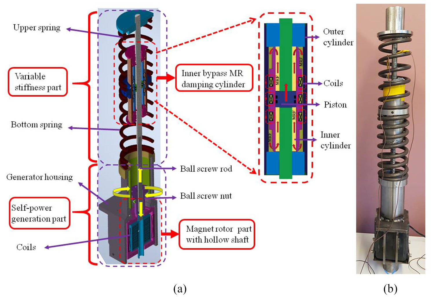
Structure and prototype of the self-powered MR damper: (a) schematic diagram and (b) prototype.
2.2. Experimental setup for the MR damper testing
INSTRON® test system has been widely used to obtain the dynamic performance of various mechanical systems. The configuration of INSTRON® test system to test the new MR damper is shown in Figure 2. Two main hydraulic grippers fixed the two ends of the MR damper. The bottom gripper is driven by a hydraulic cylinder and can move up and down to generate excitation. The upper gripper is fixed and holds the upper end of the MR damper during the test. Both displacement sensor and force sensor are installed inside the testing system to measure the real-time data. The predesigned excitation profile is programmed in the computer to excite the damper.
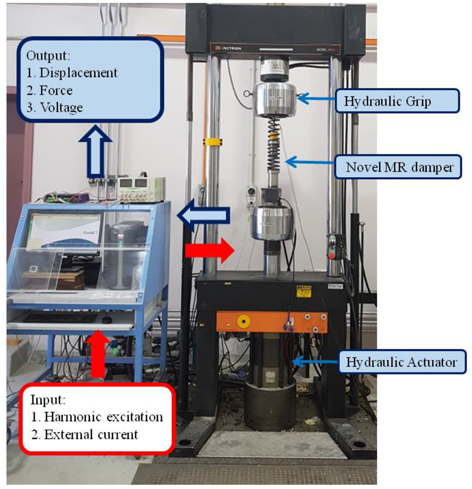
Configuration of INSTRON® test system.
2.3. The electricity generating capability of the self-powering component
In order to investigate the electricity generating capability of the self-powering component, a series of experiments were conducted under the harmonic excitation with 0.15 Hz frequency and different amplitudes of 10, 20 and 30 mm. The generator used in this study is modified from a step motor with four wires (two coil sets). The two coil sets, defined as
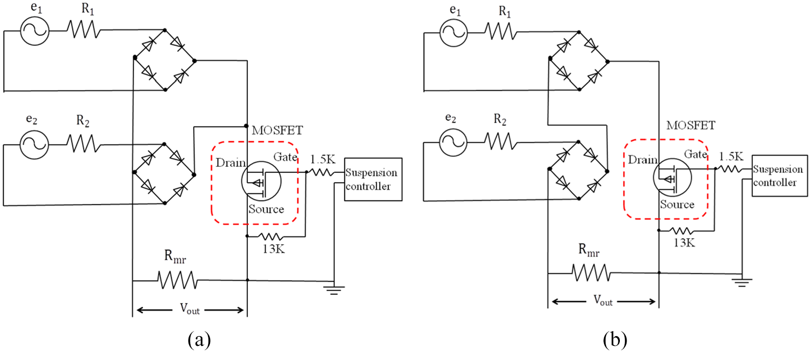
Rectifier circuits of the self-powering component: (a) parallel and (b) series.
The testing results are shown in Figure 4. Figure 4(a) presents the voltage generated by one coil
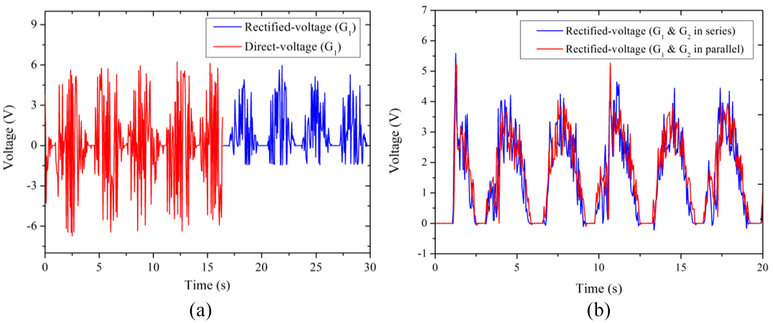
The effect of the rectifier circuit on the power generation: (a) directly generated voltage and rectified voltage of
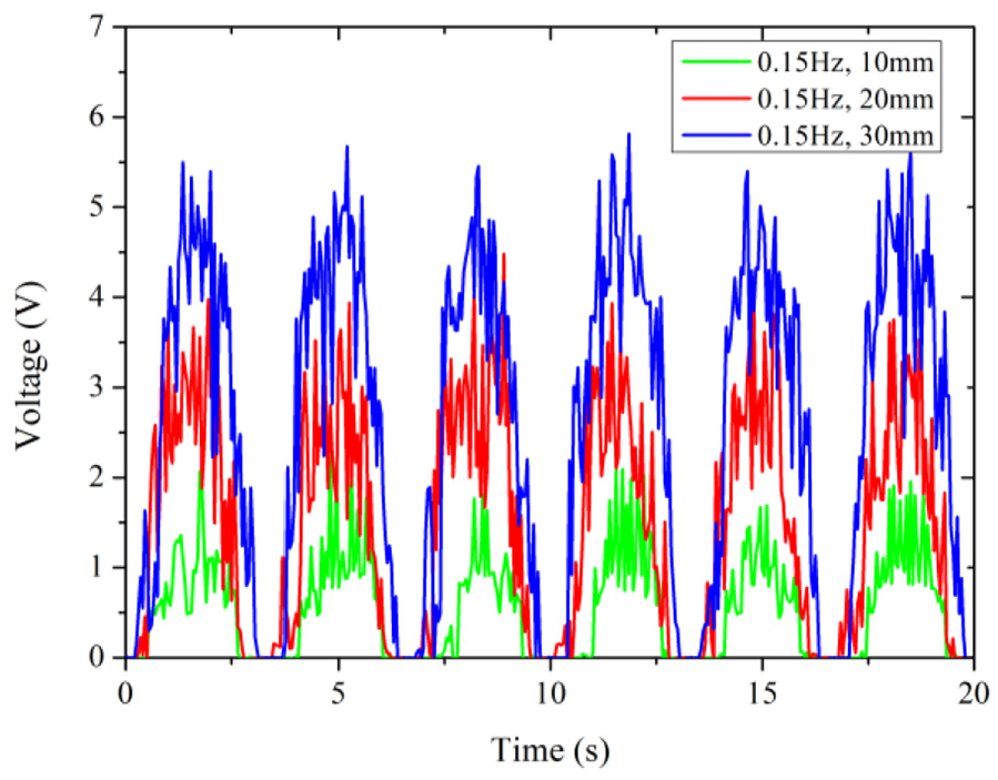
Self-generating capability under different amplitude.
After the investigation of the influence of the rectifier circuit, the effect of the excitation amplitude is further studied. The two rectifier circuits for
2.4. The variable stiffness property test
To validate the variable stiffness characteristic, a harmonic excitation with a frequency of 0.15 Hz and different amplitudes (20 and 30 mm) was chosen as the excitation signal. The self-powering component is under open-loop scenario during the test. For each amplitude, different current levels changing from 0.0 to 1.2 A with an interval of 0.4 A was used to energise the MR damper.
During the experiment, the measured data from displacement sensor and force sensor was delivered to the computer for recording. Force-displacement relationship of the MR damper was used as the primary description method in the following analyses. The measured hysteresis loops indicating the variable stiffness are shown in Figures 6 and 7. To analyse the working mechanism of the proposed MR damper, the hysteresis loop excited by 0.4 A current and 20 mm amplitude was taken as an example. It is seen that the force-displacement loop was hexagonal and that six letters from A to F were placed clockwise at the inflection points on the curve shown in Figure 6. From point A to point D, the suspension is compressed while the suspension undergoes the opposite stretching process from D to A. The segmentation from point A to B indicates the friction and damping force of the whole system, including the friction and damping force of the generator, the friction force of the ball screw and the force generated by the variable stiffness component. During the segmentation from point B to point C, the top stiff spring was compressed. In this case, The MR damper performs large stiffness. With the applied force increasing, the cylinder of the MR damper slides relatively with respect to its piston, which results in the compression of the lower soft spring. In this scenario, the two coil springs work in series and the MR damper demonstrates soft stiffness, as indicated by the segmentation CD. The segments DE, EF and FA are the stretch processes of the MR damper corresponding to segments AB, BC and CD.
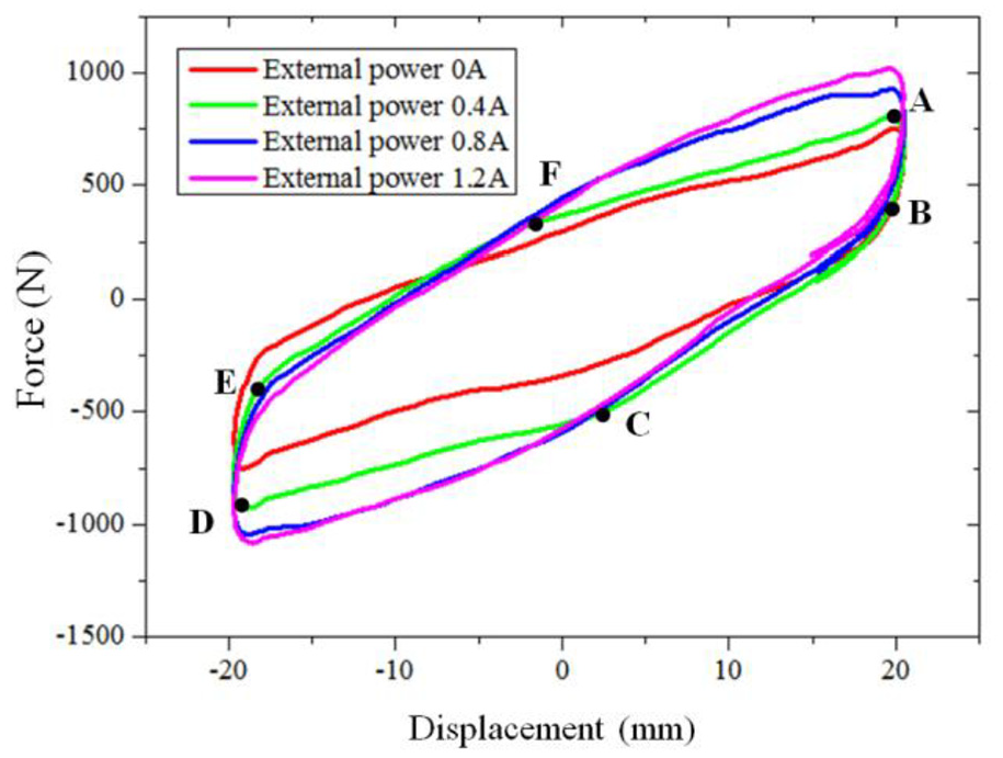
Force displacement relationship under excitation amplitude of 20 mm.
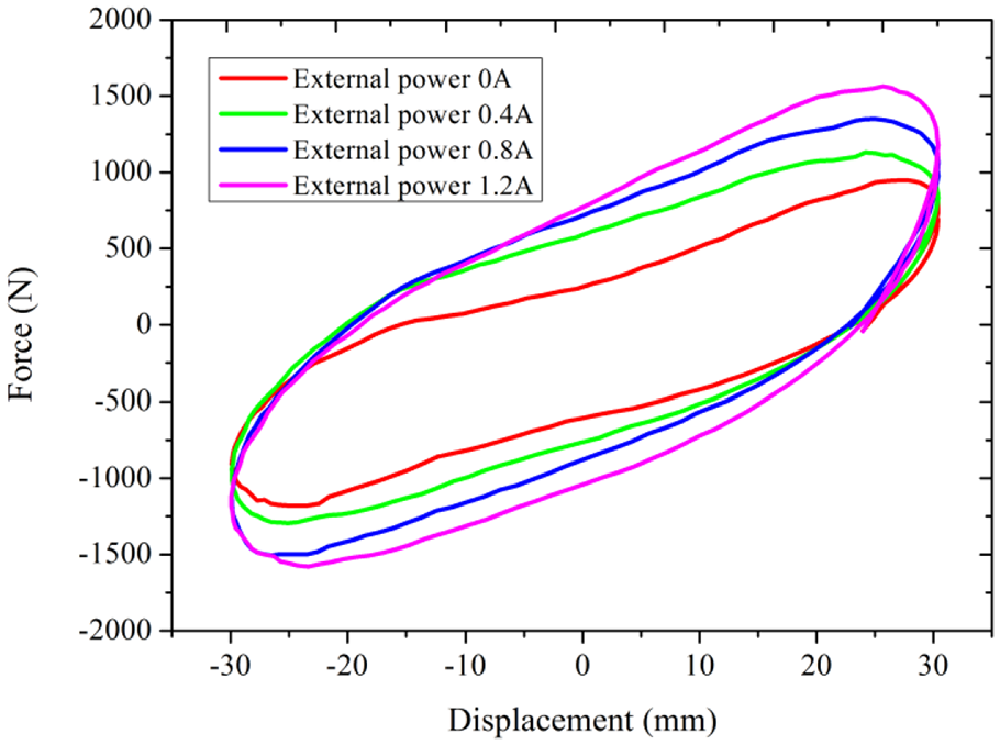
Force displacement relationship under excitation amplitude of 30 mm.
Figures 6 and 7 also indicate that the force-displacement loop tends gradually to be parallelogram rather than hexagon with the increasing current. This is because the damping force of the inside MR damping cylinder is large enough to hold the deformation of the top spring and thus the MR damper demonstrates large stiffness across the whole stroke.
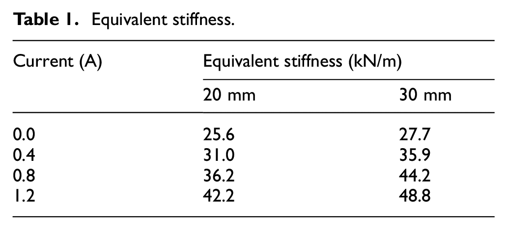
The equivalent stiffness of the MR damper can be calculated through the slope of various loops under 20 and 30 mm excitation amplitudes. The calculated results are shown in Table 1.
Equivalent stiffness.
In order to further verify that the self-powered energy is sufficient to control the MR damper, the damping force generated from both of the self-powered MR damper and the passive MR damper are compared and presented in Figure 8. It is seen that the damping and stiffness of the self-powered MR damper are much larger than the passive MR damper, which means the self-generated power is enough to control the MR damper.
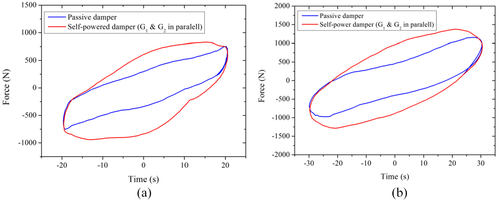
Property comparison between the passive MR damper and self-powered MR damper: (a) 20 mm amplitude and (b) 30 mm amplitude.
3. Mathematic models of the proposed MR damper
In order to describe the property of the suspension system, two models, that is, the variable stiffness dynamic model for the MR damper and the electricity generating model for the self-powering component, were built.
3.1. Dynamic model for MR damper
The dynamic model of the MR damper is shown in Figure 9, which is composed of a self-powered part and a variable stiffness part. The dynamic force generated by the self-powered part consists of a damping coefficient
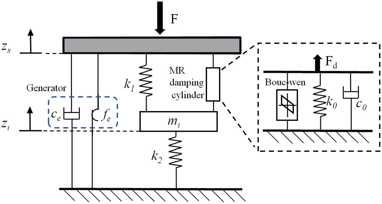
Dynamic model of the variable stiffness damper.
The output force of the damper consists of three parts: the damping force from MR damper, the spring force from springs and the force generated by the generator. The resultant force can be calculated by:

where
If:

If:

where

where c0 is viscous damping parameter, a is the evolutionary coefficient, k0 is the stiffness coefficient.
The parameters in equation (4) can be calculated as follow:
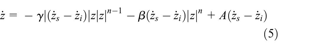


where A, γ, β are the hysteresis parameters, i is the control current.
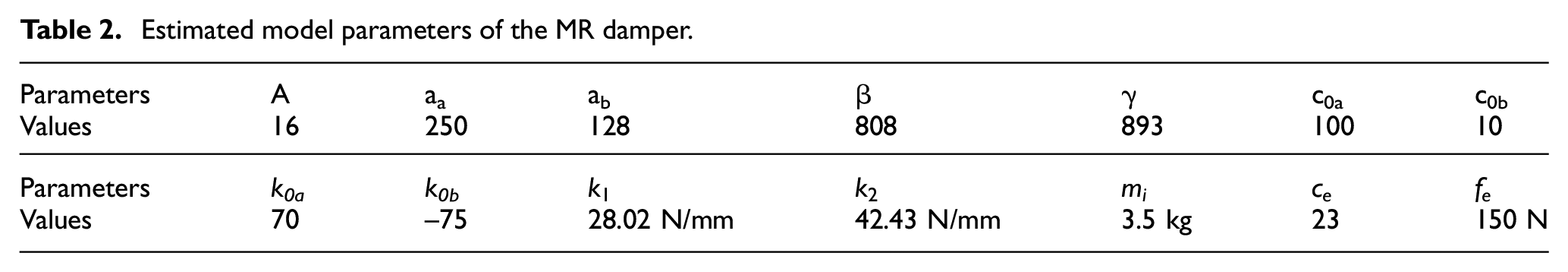
All the parameters of the Boue-Wen model can be determined through the parameter identification using the testing results of the MR damper. The parameter identification is conducted using Matlab/Simulink and the identified parameters are given in Table 2.
Estimated model parameters of the MR damper.
The fitting results between the modelling result and the experimental results are given in Figure 10. This figure shows that the established model can predict the dynamic performance of the MR damper accurately.
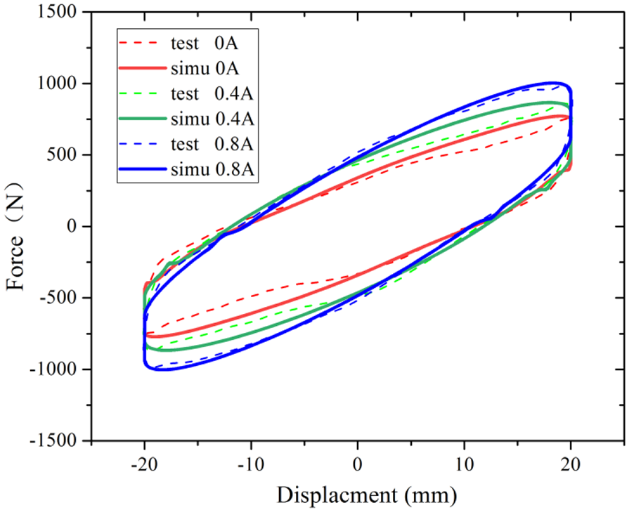
Comparison between simulation and experimental results.
3.2. Electricity generating model of the self-power component
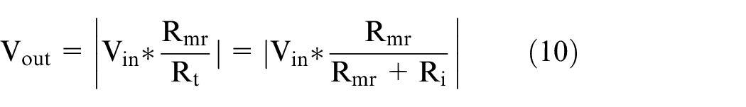
According to the rectifier circuit, the total resistance of the circuit can be calculated by:

where
Since the two groups of coils were parallel in the circuit, the voltage
where


where
The relationship between the linear motion speed of the ball screw rod and the rotation speed of the screw nut can be expressed as:
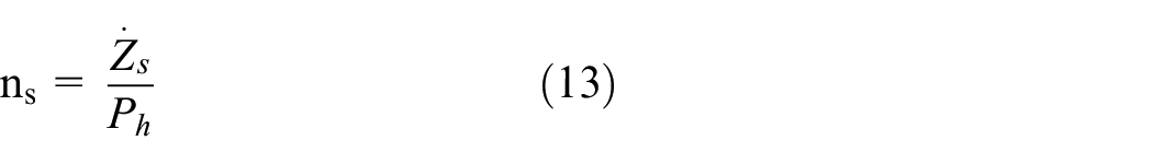
where
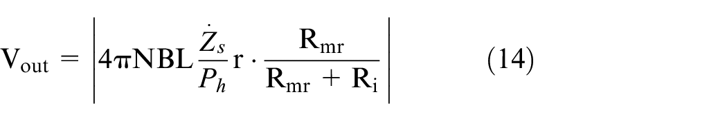
According to the above equations, the relationship between the self-generated voltage and the velocity of the ball screw rod can be expressed as:
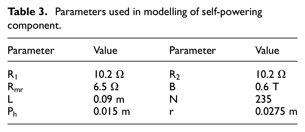
The circuit parameters are indicated in Table 3.
Parameters used in modelling of self-powering component.
The comparison between the simulated voltage and the experimentally obtained result is shown in Figure 11. According to the figure, the simulated voltages are very close to the experimental results, which means the proposed model can predict the electricity generating performance of the self-powering component well.
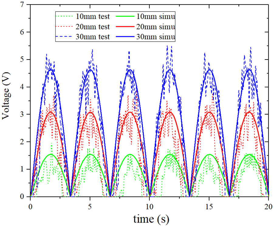
Modelling results of the self-powering component.
4. Experimental evaluation of the self-powered variable stiffness damper on a quarter-car test rig
4.1. Quarter-car test rig
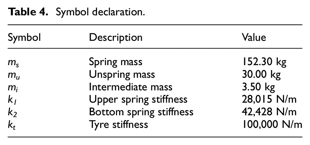
Quarter-car test system has been widely used to evaluate the ride comfort of vehicle suspensions. As shown in Figure 12, a quarter-car test system which consists of a car body, suspension system, controller and road excitation generation system was established. The specifications of the quarter-car test system are given in Table 4. The road excitation generation system includes a hydraulic cylinder, a hydraulic valve, a hydraulic station, a laser sensor and a real time excitation controller using PID control algorithm (Model: myRIO-1900, NI Corp.). Meanwhile, the suspension control system consists of two laser sensors, MOSFET (STP60NF06) switch and a real time suspension controller (Model: myRIO-1900, NI Corp.). Laser sensors are used to collect the displacement of the sprung mass and the stroke of the MR damper. The MOSFET switch is controlled by the suspension controller and it is used to control the working mode of the self-powering circuit.
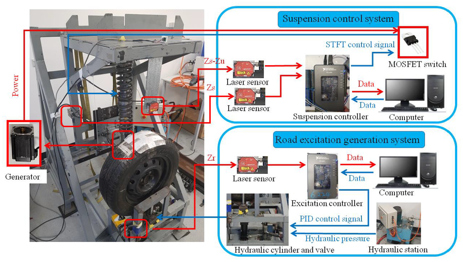
Quarter car test system for the novel suspension evaluation.
Symbol declaration.
The circuit works in the following two modes, switch-on and switch-off. When the input PWM signal from suspension controller is +10 V, the MOSFET switch is on, thereby connecting the coil of the MR damper in series with the self-powered component. In this case, the MR damper is energised by the self-powered energy, resulting in the increase of the damping force as well as the stiffness of the device. On the contrary, when the suspension controller sends a 0 V signal to the MOSFET, it will be off and the circuit will be open. In this case, the self-powered energy will not be used to power the MR damper.
4.2. STFT control strategy
For semi-active suspension, the control strategy is also a significant part of the system. STFT control strategy (Nagarajaiah and Varadarajan, 2005; Sharma et al., 2013) is a popular and effective algorithm for non-resonance vibration control. The STFT algorithm splits the signal into small time segments and then analyses each time segment to find their dominant vibration frequency (Narasimhan and Nagarajaiah, 2005). After obtaining the dominant frequency, it will be compared with a threshold frequency. The threshold frequency is the frequency corresponding to the intersection point of the transmissibility of the passive mode (0 A) and self-powered mode. Upon comparing the dominant frequency with the threshold frequency, the controller will send a control signal to the MOSFET switch so that the stiffness of the self-powered MR damper can be adjusted to avoid the resonance.
4.3. Evaluation under sweep excitation
The harmonic excitation with sweep frequencies from 0.5 to 2.75 Hz was used to excite the quarter car test rig so as to obtain the transmissibility of the vehicle suspension. The transmissibility is the ratio of the car-body displacement to the road excitation displacement with respect to the sweep frequency, the lower the better. Four kinds of suspensions were tested on the quarter-car system: three passive suspensions energised by constant external currents of 0, 1.2 and 2 A, and self-powered suspension using the self-generated energy. For comparison purpose, three vibration transmissibilities of the three passive suspensions were measured, presented together with the vibration transmissibility of the self-powered suspension in Figure 13. It is observed that the resonance frequency of the passive suspension increases with the increase of the applied current, indicating the frequency shift property. This is because the increase of the applied current leads to the increase of the damper stiffness. Then comparing the passive transmissibility (0 A) to the self-powered one, an intersection is found with the intersecting frequency to be 2.1 Hz. Here the frequency of 2.1 Hz is defined as the threshold frequency. It is seen that if the excitation frequency is within the range from 0.5 to 2.1 Hz, the transmissibility of the self-powered suspension is much lower than the passive one; otherwise, the passive transmissibility is the lower one. As the control target is to achieve the lowest transmissibility, the control signal sent to the MOSFET switch can be expressed as equation (15).
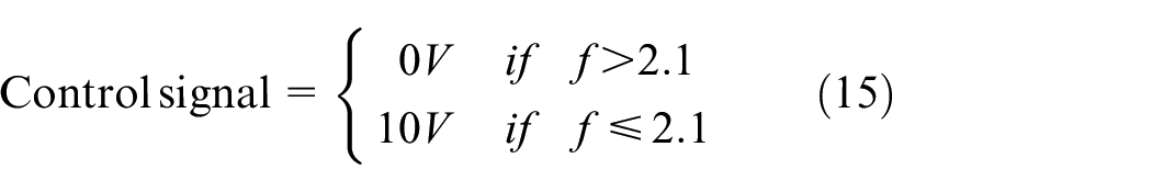
Specifically, if the dominant excitation frequency is lower than the threshold frequency, the suspension controller will send a 10 V signal to turn on the MOSFET switch and the self-powered energy will be used to control the MR damper. In this case, the stiffness of the damper is high and the segment of self-powered transmissibility within 0.5 to 2.1 Hz will be achieved. Otherwise, the MR damper will work in passive mode (0 A) and the segment of passive transmissibility over 2.1 Hz will be achieved. Based on the above narrative, the lowest transmissibility which is composed of the two segments of transmissibility can be obtained across the whole frequency range using the STFT controller.
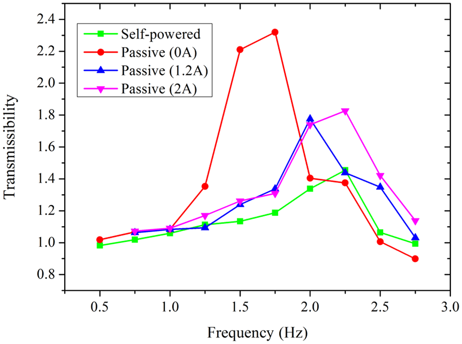
Transmissibility under sweep excitation.
4.4. Evaluation under random excitation
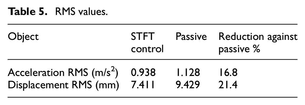
This section evaluated the vibration isolation performance of the MR damper under a random road excitation. During the evaluation, the STFT controller identifies the instantaneous dominant excitation frequency and then uses the control rule in equation (15) to control the MOSFET switch. The displacement and acceleration responses of the sprung mass are important indications of the ride comfort achieved by a vehicle suspension system. These indexes are the core evaluation criteria and will be applied to the subsequent analysis. Figure 14 presents the comparison of accelerations between the passive open loop suspension (0 A) and the self-powered closed loop suspension using the STFT control. It can be seen that the acceleration of the controlled case is much lower than that of the passive suspension. Figure 15 indicates the control signal (voltage) and the self-powered energy during the STFT control. The control signal switches between 0 and 10 V according to equation (15). The generated power changes consistently with the control signal, that is, when the control signal is 10 V, the electric energy can be collected and used to power the MR damper; otherwise, no energy was applied to the MR damper. Figure 16(a) and (b) present the displacement comparison between the passive suspension and self-powered suspension in time domain and frequency domain, respectively. For both the time domain and the frequency domain, the self-powered suspension under the STFT control performs better than the passive suspension in reducing the displacement. The RMS values for both acceleration and displacement are calculated and listed in Table 5. The quantitative analysis results demonstrate that the STFT controlled self-powered MR damper reduces the acceleration and displacement by 16.8% and 21.4% respectively compared to the passive suspension.
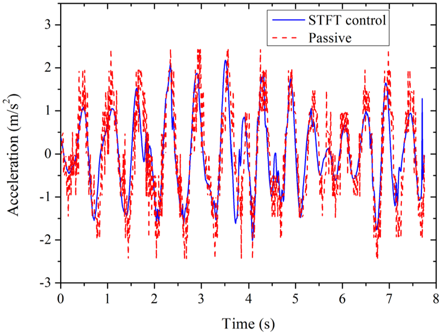
Acceleration comparison between the controlled MR damper and passive MR damper.
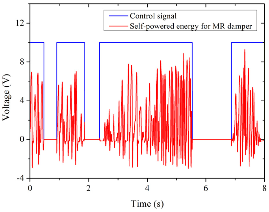
The control signal and self-powered energy of the MR damper under random excitation.
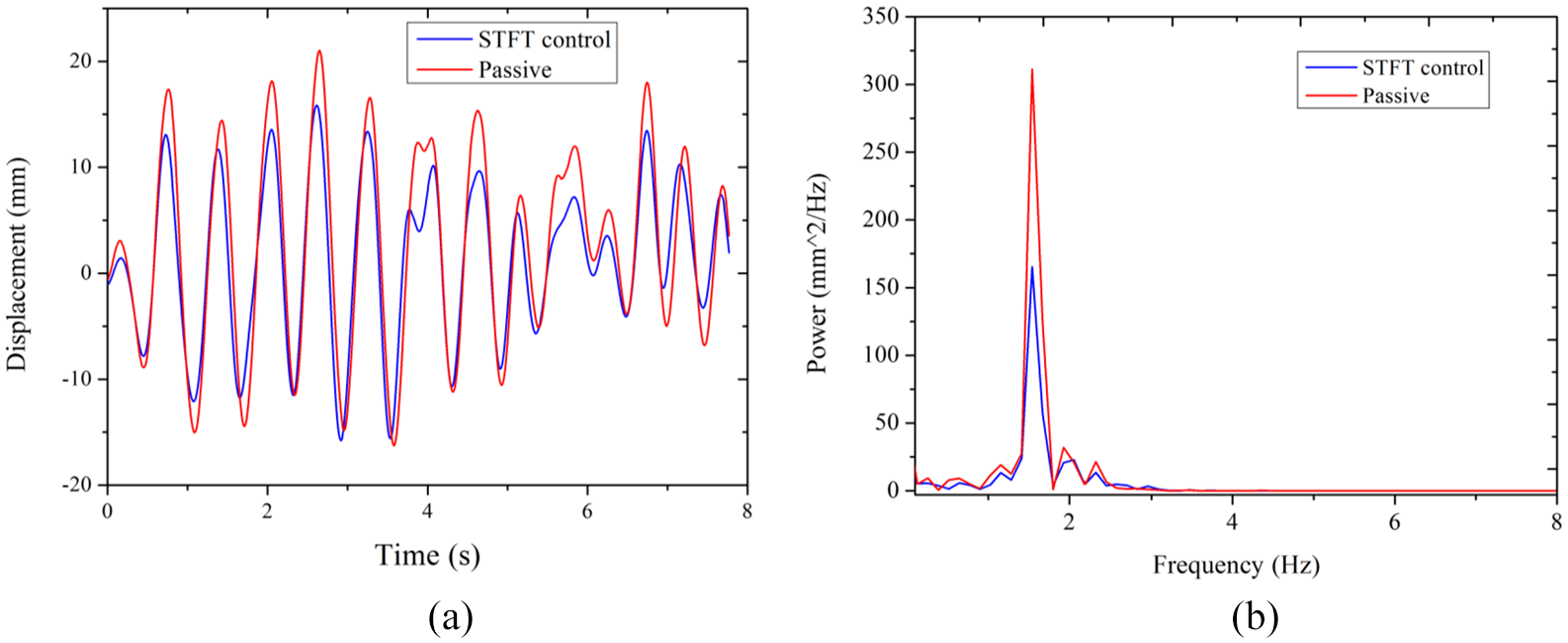
Displacement response comparison between passive suspension and controlled MR suspension: (a) time domain and (b) frequency domain.
RMS values.
5. Conclusion
In this paper, a semi-active vehicle suspension which can provide variable stiffness and self-generating electric power was successfully developed. Experimental tests have been conducted to evaluate the stiffness variable feature and the self-powered generation capability. The testing results show that the self-powered generation component can produce sufficient electric power to vary the stiffness of the suspension. A mathematic model was then established and used to predict the performance of the MR damper accurately. The evaluation results of the self-powered MR damper on a quarter car test rig demonstrate that the self-powered suspension controlled by the STFT controller outperforms the passive suspension, with the acceleration reduced by 16.8% and displacement reduced by 21.4% compared with the passive case.
Footnotes
Declaration of conflicting interests
The author(s) declared no potential conflicts of interest with respect to the research, authorship, and/or publication of this article.
Funding
The author(s) disclosed receipt of the following financial support for the research, authorship, and/or publication of this article: This research is supported by ARC Linkage Grant (LP150100040).