






Abstract
Magnetorheological impact dampers (MRIDs) have been widely investigated as an effective strategy for mitigating the harmful effects of impact shocks and vibrations. However, flow-mode MRIDs suffer from strong velocity sensitivity and high off-state forces, whereas conventional shear-mode designs deliver low velocity sensitivity at the expense of limited load capacity. To address this trade-off, this study proposes a novel shear-mode twin-tube MRID that increases the effective shear-activated magnetorheological fluid (MRF) volume within a confined envelope. Magnetic coils are placed between two concentric annular channels spanning the long operational stroke to improve magnetic-field utilization and dissipation efficiency without enlarging the package. The work comprises development of a quasi-static force model for shear-mode behavior, a FEM-based, performance-index driven multi-objective optimization of the magnetic circuit and geometry for impact requirements, and fabrication of an optimized prototype. Comprehensive cyclic loading experiments were performed to characterize damping force performance under varied coil currents and frequencies. Results show good agreement between model and measurements, pronounced field-dependent force generation with modest velocity sensitivity, and tunable increases in energy dissipation as current is raised. Subsequent drop-weight tests further demonstrate the effective impact mitigation capability of the proposed MRID under practical impulsive loading environments.
Introduction
An impact refers to the forceful contact between two or more objects over a short duration, during which energy is rapidly transferred and may lead to serious consequences. Such events range from common occurrences, including mechanical shocks in vehicles (Marshall and Riley, 2020), heavy machinery operations (Saberi et al., 2021), and helicopter hard landings (Yang et al., 2020), to catastrophic scenarios such as vehicle collisions (Sun et al., 2021) or elevator accidents (Hou et al., 2022). Although impacts are natural phenomena, the released energy can cause severe injuries or structural failures, making their mitigation essential for safety and integrity. One of the most effective strategies to alleviate these detrimental effects is the use of impact dampers, which are generally classified into three categories: passive, active, and semi-active, based on their control mechanisms and adaptability. Passive impact dampers dissipate energy through fixed mechanical properties without external power, providing simplicity and reliability but limited adaptability under dynamic or unpredictable conditions (Chaari et al., 2017; Shi et al., 2019). Active impact dampers, on the other hand, overcome these drawbacks by employing sensors, actuators, and control systems to adjust damping forces in real time (Maciejewski et al., 2010; Son et al., 2018); however, this performance advantage comes at the cost of increased complexity, energy consumption, and implementation expense. The last category, semi-active impact dampers, serves as a compromise between passive and active systems (Feng et al., 2022b; Lu et al., 2024). They achieve greater adaptability than passive devices but operate with lower power demand and simpler control than fully active counterparts.
Recent advancements in smart materials and high-performance computing have enabled adaptive semi-active damping systems for diverse impact scenarios. Among these, magneto-rheological fluids (MRFs), comprising micron-sized ferromagnetic particles suspended in a carrier liquid with stabilizing additives, are especially attractive due to their rapidly and reversibly tunable rheological properties, high load capacity, and energy efficiency (Ashour et al., 1996). Leveraging these features, MRF-based impact dampers (MRIDs) can precisely modulate damping forces under a controllable magnetic field, and ongoing research has continuously improved their structural design and practical performance. MR dampers in general can operate under three typical modes: flow, shear, and squeeze (Oh et al., 2022). In the squeeze mode, the MRF is compressed between two approaching surfaces, generating very high damping forces (Dong et al., 2024; Meng et al., 2019). However, the inherently short stroke and high sensitivity of damping force to small gap variations limit its applicability. Since long-stroke operation is essential in impact scenarios to ensure effective energy dissipation and a soft-landing effect (Wereley et al., 2011), the squeeze mode is generally unsuitable for MRIDs. In another approach, the flow mode produces damping force through the pressure drop as the MRF flows through an annular channel between two chambers under a magnetic field. This mode is widely adopted for MRIDs owing to its high energy absorption over long strokes, large load capacity, and maturity for large-scale applications. Building on this concept, Zheng et al. (2022) investigated the feasibility of employing multiple MR shock absorbers with an internal-bypass, bi-fold configuration to achieve elevator soft landing under high impact velocities. In the MR damper models proposed by Han et al. (2020), the MRF flows through orifices and recoil valves with configurable magnetic core parameters, producing asymmetric compression/extension behavior and robust fail-safe performance that enhance the stability and efficiency of small-aircraft landing gear. Later, to improve the energy dissipation effectiveness of an aircraft landing gear system, Kang et al. (2023) presented a MR shock strut employing a single-ended monotube MR damper with an internal annular orifice and an external bypass. Alternatively, a multi-stage flow-mode MR damper featuring stacked axial circular-hole and radial disk-shaped channels was integrated into a semi-active valve-controlled hydraulic actuator to mitigate underdamped responses and enhance impact resistance under sudden load changes (Ma et al., 2023).
In conventional flow-mode MR dampers, the uncontrollable viscous force increases quadratically with velocity, often dominating the total damping output and producing excessive transmitted peaks during high-speed impacts that endanger occupants and structures. To achieve a desirable plateau effect and improve controllability, various control algorithms have been proposed (Feng et al., 2022a; Han et al., 2019; Huang et al., 2025; Li et al., 2023; Zheng et al., 2022). However, as these approaches remain limited by response time, power demand, and system complexity, recent works have focused on structural design modifications to inherently shape the damping-force profile and reduce reliance on sophisticated control. Jin et al. (2021) presented a new linear flow-mode MR damper for impact mitigation, featuring a hybrid powering system that produces a current opposite to the initial current to achieve rate-dependent softening characteristics without closed-loop control. In the study of Xi et al. (2021), a passive adaptive MR energy absorber was proposed to maintain a constant damping force over the full piston stroke, in which an axial variable damping gap is preset along the piston travel so that viscous and MR magnetic damping compensate each other as velocity changes. Later, Wang et al. (2025) introduced a novel flow-mode MR damper with multiple parallel relief orifices designed to mitigate excessive initial impact peaks and enhance plateau behavior under high-impact loads. Although extensive efforts have been made to realize the plateau effect in flow-mode MR dampers, their inherently high velocity sensitivity and elevated off-state force (i.e. the force generated in the absence of a magnetic field) remain fundamental drawbacks. These characteristics cause the dynamic range, defined as the ratio of maximum to minimum damping force under different currents, to shrink rapidly with increasing velocity, thereby degrading controllability. In addition, energy dissipation efficiency declines even at low impact levels, as large initial damping forces quickly diminish with decreasing velocity, leaving later stages less effective. To address these issues, researchers have explored shear-mode operation for MRIDs, in which the MRF undergoes pure sliding within a continuous annular channel without bulk flow. This configuration significantly reduces viscous contribution at high speeds, yielding lower velocity sensitivity, a larger dynamic range, and smoother energy dissipation along the stroke. Reflecting these advantages, Nguyen et al. (2014) performed an optimal-design study of MR dampers for front-loaded washing machines, analyzing shear-mode configurations featuring varied geometries and coil numbers, with and without a nonmagnetic bobbin, to minimize off-state force. Aiming at enhanced vibration control in variable-mass systems such as impeller-type washing machines, Deng et al. (2018) developed a direct shear-mode MR suspension rod with four coils in series, offering a theoretically unlimited stroke through its non-piston structure. In another application, Bai et al. (2018) introduced a power-generating shear-mode MR energy absorber employing a ball-screw and generator to convert linear motion into rotational torque, enabling simultaneous energy harvesting and a wide, nearly velocity-independent damping range. To improve controllability under high-speed impacts, a multi-coil, long-stroke shear-mode MRID was proposed by Deng et al. (2022), which effectively reduced velocity sensitivity and maintained nearly constant peak forces compared with the conventional flow-mode type. Recently, Nguyen et al. (2025) designed and tested a compact shear-mode MRID with four rectangular coils, enabling progressive magnetic activation and smooth force buildup throughout the piston stroke without complex control.
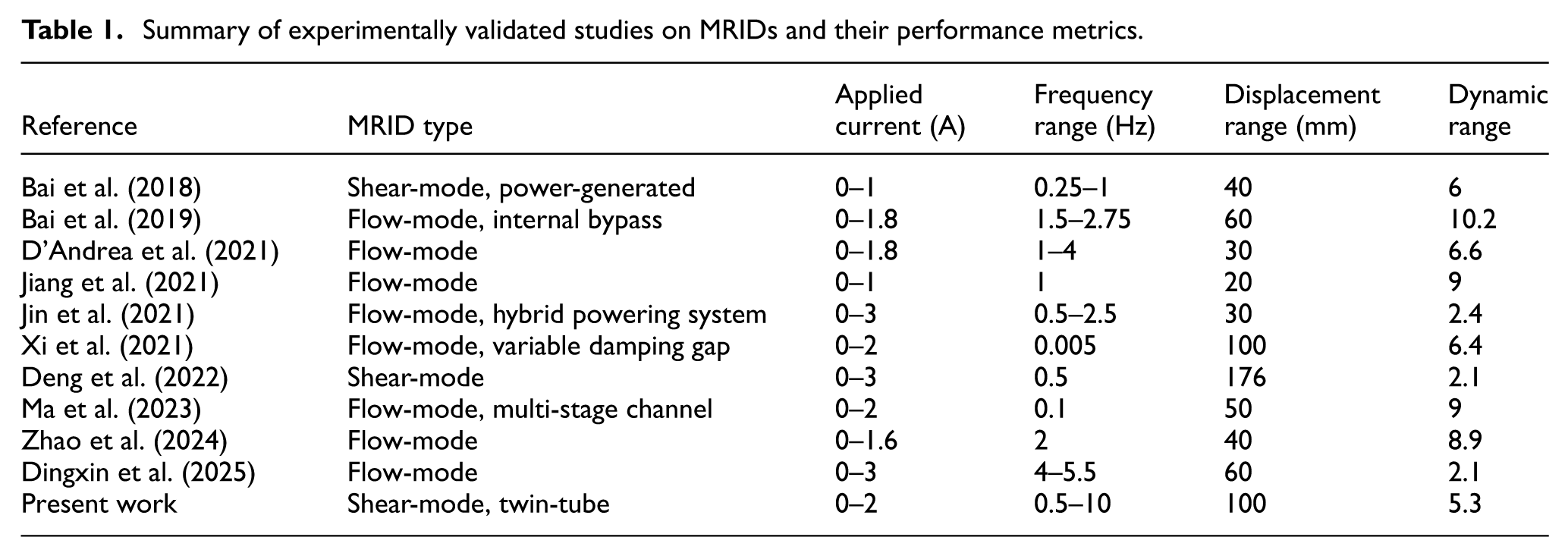
Table 1 summarizes experimentally validated studies on MRIDs and their key performance metrics. Since flow-mode MRIDs suffer from high velocity sensitivity and elevated off-state forces while conventional shear-mode designs trade these advantages for limited load capacity, this study proposes a novel compact shear-mode MRID to overcome these trade-offs. The damper adopts a twin-tube configuration that can increases the effective MRF volume, and thus load capacity, within a confined space. Magnetic coils are arranged between two concentric annular channels over the long operational stroke, enhancing magnetic-field utilization and energy-dissipation efficiency without enlarging the package. A multi-objective FEM-based optimization was performed to refine the geometry and coil parameters for key impact criteria, yielding an effective design for high-energy, fast-response, long-stroke applications. Finally, the optimized prototype was fabricated and validated through cyclic loading experiments, followed by detailed performance evaluation and discussion.
Summary of experimentally validated studies on MRIDs and their performance metrics.
Configuration and principle
Figure 1(a) illustrates the configuration and working principle of the proposed shear-mode twin-tube MRID. The device consists of three main coaxial components: a central cylinder core, an outer cylinder housing, and a hollow piston that slides axially relative to both the cylinder core and cylinder housing. The inner and outer surfaces of the piston form two concentric annular channels, which are filled with MRF to create a twin-tube structure. A series of electromagnetic coils are embedded circumferentially within the piston, separated from the two channels by thin nonmagnetic partitions and serving as magnetic field generators for MRF activation. The MRF is sealed between four O-rings mounted on the piston rod and translates together with the piston; therefore, its volume remains constant during operation. The rod intrusion into the cylinder is accommodated by a bottom air cavity located beneath the MRF module. This cavity is vented to the ambient environment through calibrated vent holes that enable bidirectional air exchange, thereby substantially minimizing internal pressure buildup and the associated contribution of pneumatic stiffness. The structural integrity and alignment are ensured by plain bearings and circlips positioned at appropriate interfaces.
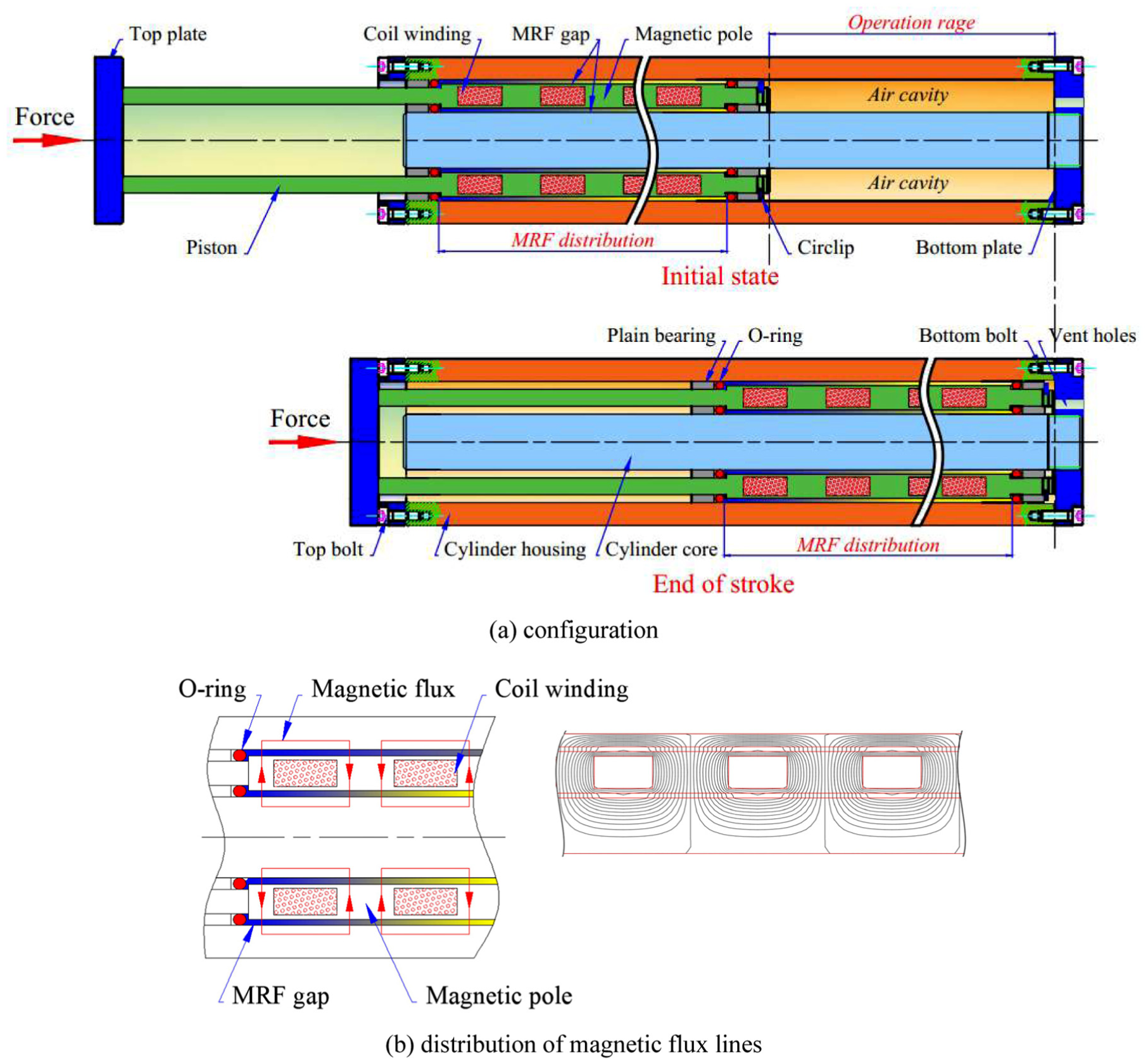
Concept of the shear-mode twin-tube MRID: (a) configuration and (b) distribution of magnetic flux lines.
The proposed MRID operates in a shear mode, where shear deformation is induced by the relative axial motion between the piston and the thin MRF layers confined in the annular channels. Under non-magnetized state, the MRF behaves as a Newtonian fluid, offering small resistance to motion and thus a low off-state force. When the coils are energized, magnetic flux is generated and quickly saturates at the thin partitions. This flux is then forced to pass through the twin MRF gaps, toward the cylinder core and cylinder housing, thereby establishing closed magnetic circuits across these channels, as shown in Figure 1(b). The applied magnetic field activates the MRF and consequently rises the shear resistance to produce a controllable damping force. The twin-tube configuration enables two annular MRF layers to operate simultaneously, effectively widening the active area and enhancing the damping capacity without enlarging the overall device envelope. Moreover, the distributed magnetic poles and elongated coil arrangement along the stroke length promote fully magnetic field utilization, leading to improved energy dissipation efficiency.
Mathematical modeling
Prior to modeling a MR damper, it is essential to analyze the dynamic characteristics of the controlled system to determine the expected damping performance. A MR damper-based suspension system can be modeled as a variably damped spring–mass system. The governing equation of motion for such a single-degree-of-freedom system subjected to an impulsive load at time t = 0 is expressed as:

The corresponding steady-state solution of the response is given by:

where m is the mass of the post-collision system, c is the damping coefficient, k is the spring stiffness, x(t) is the relative displacement of the suspension system caused by the impulse excitation, and the subscript 0 denotes the initial state (at the time t = 0). The damping ratio ζ, natural frequency ω n , and damped frequency ω d are given by the following equations, respectively:

Considering that the suspension system is at rest before the impulsive load is applied and the magnitude of the impulse is S, the response of the system in equation (2) becomes:

The essential aspect of MR damper modeling lies in establishing the dependence of damping force on the structural geometry and magnetic field distributed within the device. The total damping force F d generated by the damper consists of three primary components, including the field-dependent yield force F τ produced by the magnetically induced shear stress of the MRF, the field-independent viscous force F η arising from the inherent viscosity of the MRF, and the frictional force F f associated with Coulomb mechanical friction between the O-rings and sliding parts:

Figure 2 illustrates the fundamental geometric dimensions of the shear-mode twin-tube MRID, which serve as the basis for establishing its controllable damping characteristics. In this configuration, N z electromagnetic coils are evenly distributed along the damper stroke length, thereby forming N z identical MRF operating zones, each associated with a corresponding coil. Given the narrow dimensions of the annular channels, the MRF flow within these gaps is assumed to exhibit a linear velocity profile under shear. Following the Bingham plastic model, the yield force F τ and viscous force F η are determined as:


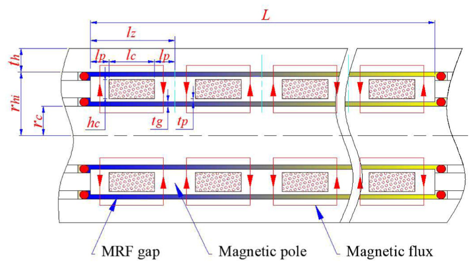
Fundamental geometric dimensions of the shear-mode twin-tube MRID.
In these equations, A
z
and l
z
denote, respectively, the surface area and length of the cylinder portion within each MRF operating zone, A and L are the total surface area and length of the cylinder in contact with the MRF, r
c
is the radius of the cylinder core, r
hi
is the inner radius of the cylinder housing,

where C and Φ Fe are the parameters associated with the MRF composition, specifically the carrier fluid and the volume fraction of iron particles, and H denotes the magnetic field intensity.
The final damping component, the friction force F f , can be estimated using the empirical formula proposed by Parker’s O-Ring (2021):

where f
c
is the O-ring compression-induced friction per unit rubbing length, l
r
is the length of the sealing contact surface, f
p
is the fluid pressure-induced friction per unit projected area, and A
s
is the projected area of the sealing surface. Since the proposed MRID operates in the shear mode, the fluid pressure-induced friction f
p
is negligible and can be omitted. As illustrated in Figure 2,

In the absence of the applied magnetic field (H = 0), the field-dependent yield stress τ y and thus the yield component F τ vanishes. The off-state damping force F0 then reduces to the sum of the viscous contribution F η and the mechanical friction F f :

Apart from the damping capacity, the response rate is also a significant parameter that governs the effectiveness of a MRID in real-time impact control. It is primarily influenced by the electrical properties of the coil and can be estimated using the electromagnetic time constant T, expressed as:

where L c and R c denote the inductance and resistance of the coil, respectively, which can be determined as:


In the above, n t is the number of winding turns per coil, Φ is the magnetic flux through the MRF gaps, I is the coil current, ρ is the resistivity of the wire material, A w is the cross-sectional area of the wire, and l w is the total wire length per coil, given by l w = πdcnt, where d c is the mean coil diameter. Assuming that the wire is wound in multiple straight stacked layers within the coil groove with filling factors k a (axial direction) and k r (radial direction), the number of turns n t can be approximately evaluated as:

in which d w is the wire diameter and A c is the cross-sectional area of the coil, structurally defined by the product of its length l c and height h c .
Structural optimization
Based on the dynamic response and quasi-static modeling presented in Section 3, the structural optimization of the shear-mode twin-tube MRID is carried out to achieve an appropriate balance among the key design criteria. A low electromagnetic time constant T is evidently desirable for impact applications, as it allows the damper to respond rapidly to sudden loading events. In addition, achieving a sufficiently high maximum damping force F d is essential to ensure effective impact mitigation and energy absorption under extreme conditions. However, increasing the maximum force typically requires enlarged structural dimensions for stronger magnetic excitation or smaller MRF gaps, which inevitably elevate the off-state force F0 due to intensified viscous and mechanical frictional effects. A high off-state force reduces the device’s dynamic range and responsiveness to sudden impacts, causing premature resistance even before the magnetic field is activated, which could transmit excessive shock to the protected structure or occupants. Therefore, in this optimization problem, the electromagnetic time constant T and the off-state force F0 are set to be minimized, while the maximum controllable damping force F d is maintained sufficiently greater than an expected damping requirement.
Since the viscous component often contributes only a small portion to the overall damping performance of shear-mode dampers, the dynamic behavior of the proposed MRID in this study can be reasonably approximated as that of a typical Coulomb friction damper. Accordingly, by equating the energy dissipated per half vibration cycle W d by the damping force of the MRID (with an equivalent viscous damping coefficient ceq) to that dissipated by the equivalent Coulomb friction force F c , the following relationship holds:

where X denotes the peak displacement reached during the first half vibration cycle. Using equation (4) and its derivative, the equivalent Coulomb friction force F c can then be expressed as:

In this study, the impulse excitation is assumed to be generated by a mass of 10 kg dropped freely from a height of 1 m. The spring stiffness k is selected as 4491 N/m based on commercially available spring specifications to ensure a practical design and an appropriate dynamic response of the system. The damping ratio ζ is set to 0.7 according to the Integral of Time-weighted Absolute Error (ITAE) criterion (Dorf and Bishop, 2011), which is widely used in dynamic system design, in order to provide a good compromise between fast response and limited overshoot. The equivalent Coulomb friction force F c is accordingly calculated from equation (17) to be 466.88 N. Therefore, the expected damping requirement for the optimization problem is established as 467 N.
In summary, the structural optimization of the shear-mode twin-tube MRID is formulated as a constrained multi-objective problem, mathematically stated as follows:

The design variables of the optimization problem are the principal geometric parameters that define the MRF operating zones of the damper, comprising: the length l c and height h c of the coil, the length of the magnetic pole l p , the radius of the cylinder core r c , and the thickness of the cylinder housing t h , as shown in Figure 2. It is worth noting that during optimization, the thickness of the MRF gaps t g tends to decrease to strengthen the magnetic field within the gaps, thereby increasing the maximum controllable damping force. Likewise, the thickness of the thin partitions t p should be ideally minimized so that these regions quickly reach magnetic saturation and thus more effectively drive flux through the MRF gaps, improving magnetic field utilization efficiency. Reducing excessively t g and t p , however, introduces significant manufacturing challenges in maintaining dimensional tolerances and mechanical integrity of the device. Therefore, these two parameters are not treated as design variables but are fixed empirically at 1 mm.
The input data for the simulation are summarized as follows. The operating zone of the proposed MRID is confined within a cylindrical space of 100 mm in length and 30 mm in radius. The magnetic components are made of commercial C45 steel, while 28-gage copper wire with an effective diameter of 0.36 mm is adopted for winding the electromagnetic coils. The working fluid is MRF-140CG supplied by Lord Corporation (USA), which has the carrier fluid coefficient C = 1 and the volume fraction of iron particles ΦFe = 0.4. NBR rubber O-rings with a hardness of 70 Shore A are compressed by 15% to ensure reliable sealing of the MRF in the flow channels, resulting in the O-ring compression-induced friction fc = 175.1 N/m (Parker’s O-Ring, 2021). In this research, the modeling and optimization of the proposed shear-mode twin-tube MRID are performed on ANSYS Mechanical APDL platform using the finite element analysis (FEA) approach. The magnetic field behavior is analyzed through a two-dimensional axisymmetric electromagnetic model based on the PLANE233 element (ANSYS Inc, 2013), which accurately predicts the magnetic flux distribution and the resulting field intensity within the MRF domains. Figure 3(a) illustrates the finite element model of the proposed MRID. A mapped mesh is employed, with the mesh density defined by specifying the number of elements along each line segment. This meshing strategy ensures compatibility with the continuous variation of geometric dimensions during the optimization process. Figure 3(b) presents a mesh sensitivity analysis of the average magnetic field intensity in the inner and outer MRF gaps. As the mesh is refined, the results become progressively stable, with convergence observed at a mesh density of 8. Further refinement from 8 to 10 leads to only minor changes, with average deviations of 0.11% and 0.07% for the inner and outer gaps, respectively. Considering the associated computational cost, a mesh density of 8 is considered sufficient for accurate results in this study. The boundary conditions used in the magnetic field simulation include setting the magnetic vector potential (AZ) to zero at the outer boundary, which implies that the magnetic flux lines are parallel to the boundary of the computational domain. In addition, geometric symmetry and the corresponding symmetric magnetic field distribution are assumed in the model.
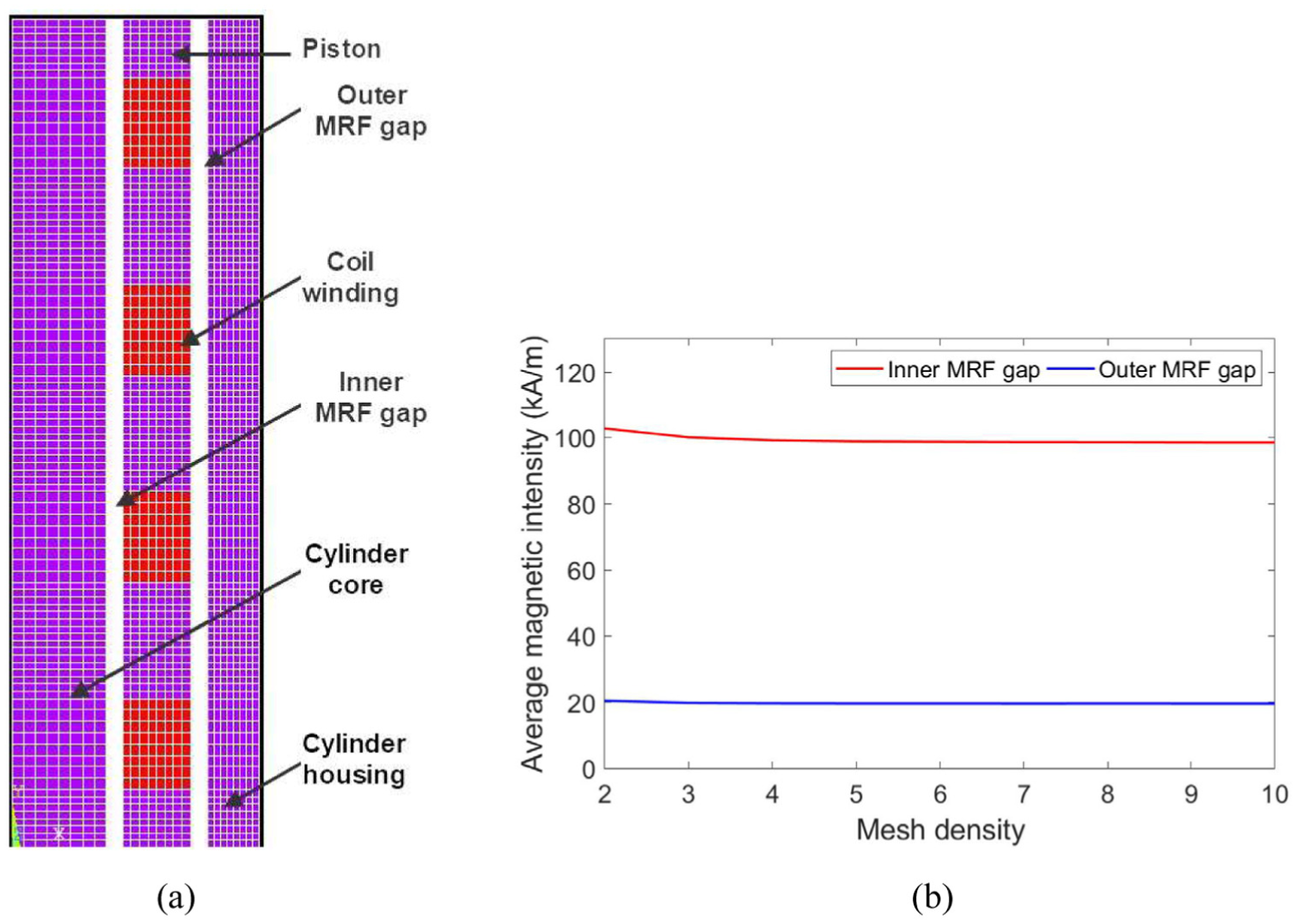
(a) Finite element model of the shear-mode twin-tube MRID and (b) mesh sensitivity analysis of average magnetic intensity in MRF gaps.
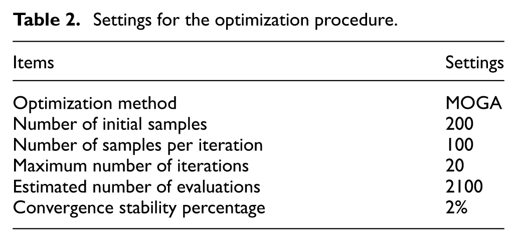
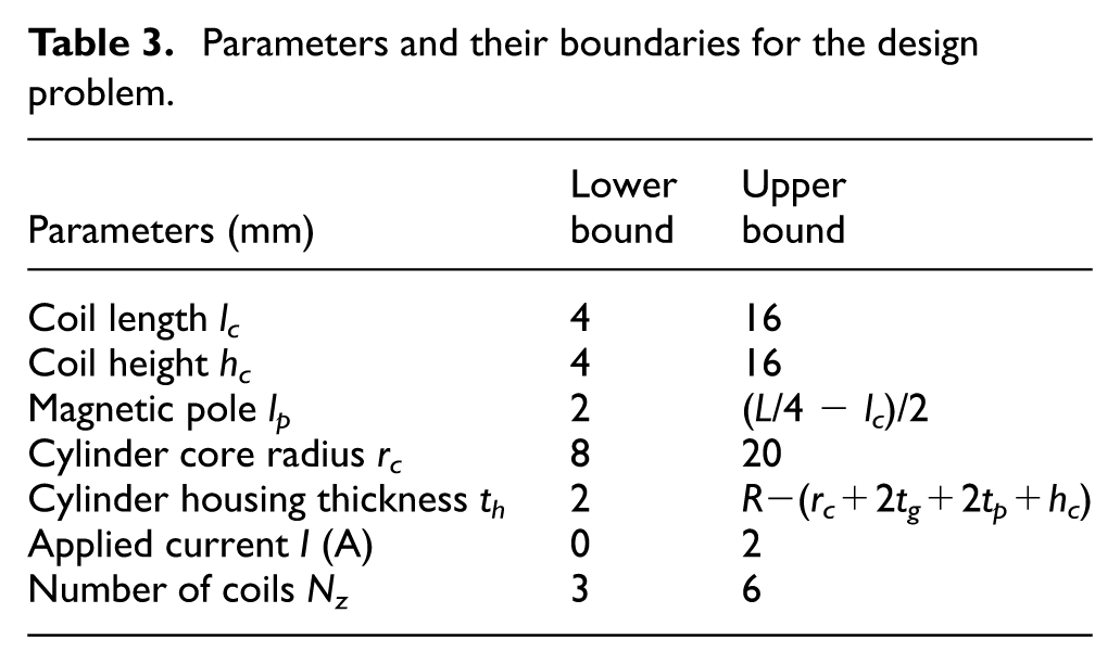
The optimization procedure is implemented with the Multi-Objective Genetic Algorithm (MOGA) integrated in Direct Optimization tool of ANSYS Workbench, which is well suited for nonlinear, multi-parameter problems involving conflicting objectives. The MOGA flowchart is shown in Figure 4. In this optimization, each candidate design is evaluated through physics-based simulations (FEA) performed in ANSYS Mechanical APDL. For every set of design variables generated by the genetic algorithm, the corresponding finite element model is solved to obtain the relevant performance responses, which are then used to compute the objective functions and constraints. Within this framework, the principal geometric parameters of the MRID are iteratively adjusted to achieve an optimal balance among the competing design criteria defined above. A convergence stability percentage criterion is employed to assess the optimization process, where population stability is characterized by its mean and standard deviation. Convergence is considered achieved when variations between successive generations become negligible. In this work, a default threshold of 2% is adopted to define convergence stability. The settings of the optimization procedure are summarized in Table 2. In addition to these continuous design variables, the number of electromagnetic coils N z is also regarded as a critical configuration parameter, as it directly governs the segmentation of the MRF operating regions and the magnetic field distribution along the stroke. Therefore, MRID configurations with different N z values are considered and examined to identify the most appropriate coil arrangement for enhanced output performance. The model parameters and their boundaries for the design problem are summarized in Table 3.
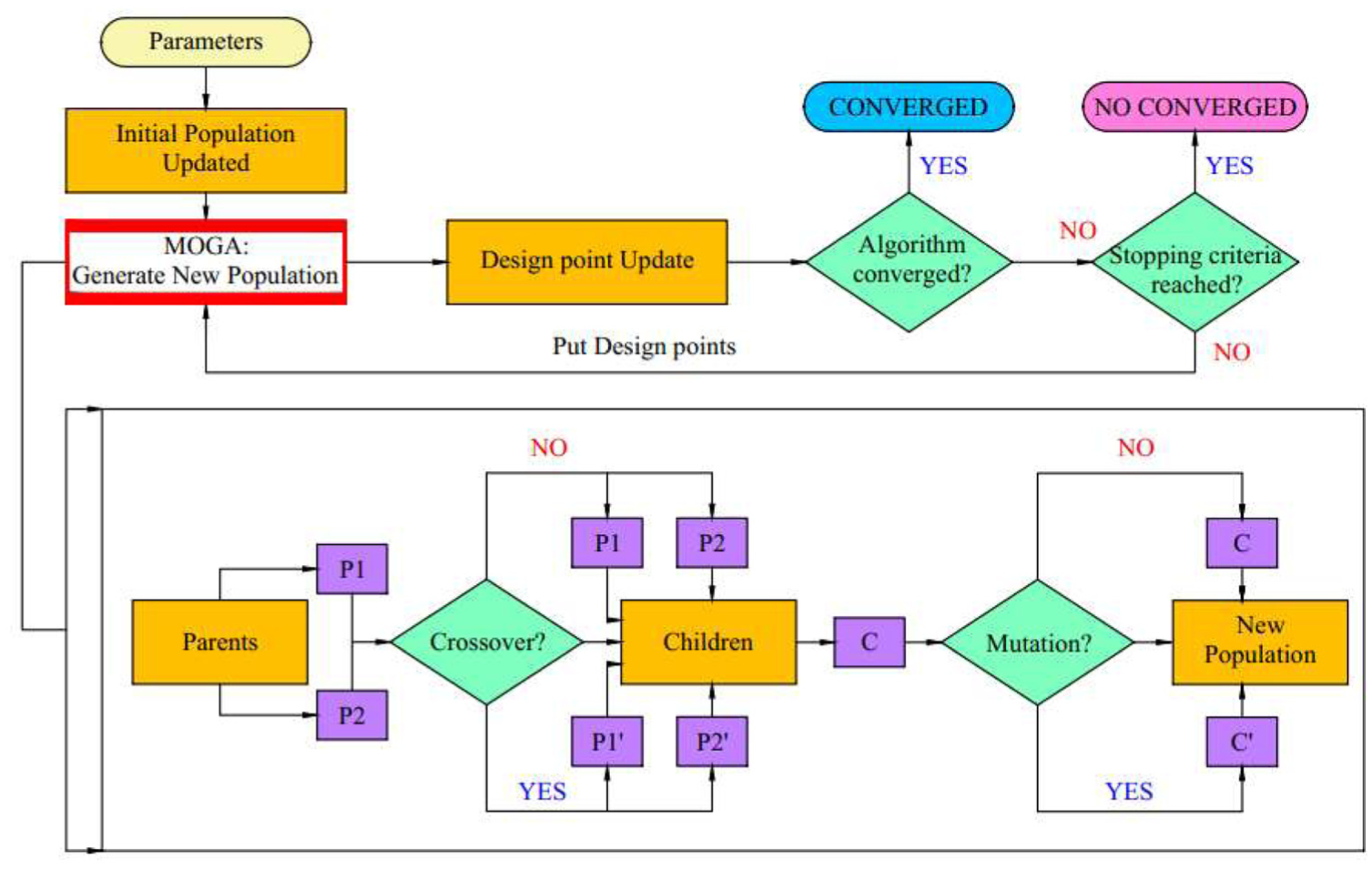
MOGA flowchart (ANSYS Inc, 2021).
Settings for the optimization procedure.
Parameters and their boundaries for the design problem.
Based on the evaluated objective functions, the candidate solutions are compared using the concept of Pareto dominance, where a solution is considered superior if it improves at least one objective without degrading the others. The algorithm then ranks the population according to Pareto dominance and applies evolutionary operators such as selection, crossover, and mutation to generate new candidate designs. Through successive generations, the population evolves toward a set of non-dominated solutions, which collectively form the Pareto frontiers representing the optimal trade-offs among the competing design objectives. Figure 5 illustrates the Pareto front charts obtained for four configurations with the number of coils N z ranging from 3 to 6. These results reveal the trade-offs between the two optimization objectives, off-state force F0 and electromagnetic time constant T, across the investigated coil-number configurations. In order to quantitatively assess and compare the candidate solutions on the Pareto fronts, a weighted performance metric is adopted, expressed as (Marler and Arora, 2010):

where PI is the performance index of the candidate solutions, and wF0 and w T denote the weighting factors assigned to the objectives F0 and T, respectively, satisfying wF0 + w T = 1. The superscript ref indicates the corresponding reference values, which are taken from the feasible Pareto solution with the lowest off-state force F0. Under this definition, a lower PI value represents a better candidate solution. In general, the weighting factors wF0 and w T can be tuned depending on the performance priorities of a specific impact application. However, the electromagnetic time constant T typically varies within a relatively limited range due to coil and magnetic circuit constraints, whereas minimizing F0 is often more critical for ensuring low passive resistance and a wide controllable force range. Therefore, in this work, wF0 and w T are set to 0.7 and 0.3, respectively, forming a moderately biased weighting distribution that places greater emphasis on minimizing the off-state force and reflects a typical practical design scenario. With this formulation, the performance indices of the candidate solutions on the Pareto fronts for the four considered MRID configurations are computed and shown in Figure 6. The results clearly indicate that the configuration with Nz = 4 delivers the most favorable output performance among the evaluated designs, as evidenced by the lowest filled blue square. Accordingly, this configuration is adopted for further development in the subsequent sections. To examine the generality of the optimization results, additional weighting combinations of wF0 and w T are also considered besides the 0.7/0.3 case. For weighting sets of 0.5/0.5, 0.4/0.6, and 0.3/0.7, the optimal solution shifts to the configuration with six coils (Nz = 6). This indicates that the optimal design tends to increase the number of coils as greater emphasis is placed on minimizing the electromagnetic time constant T, which is consistent with electromagnetic design principles.
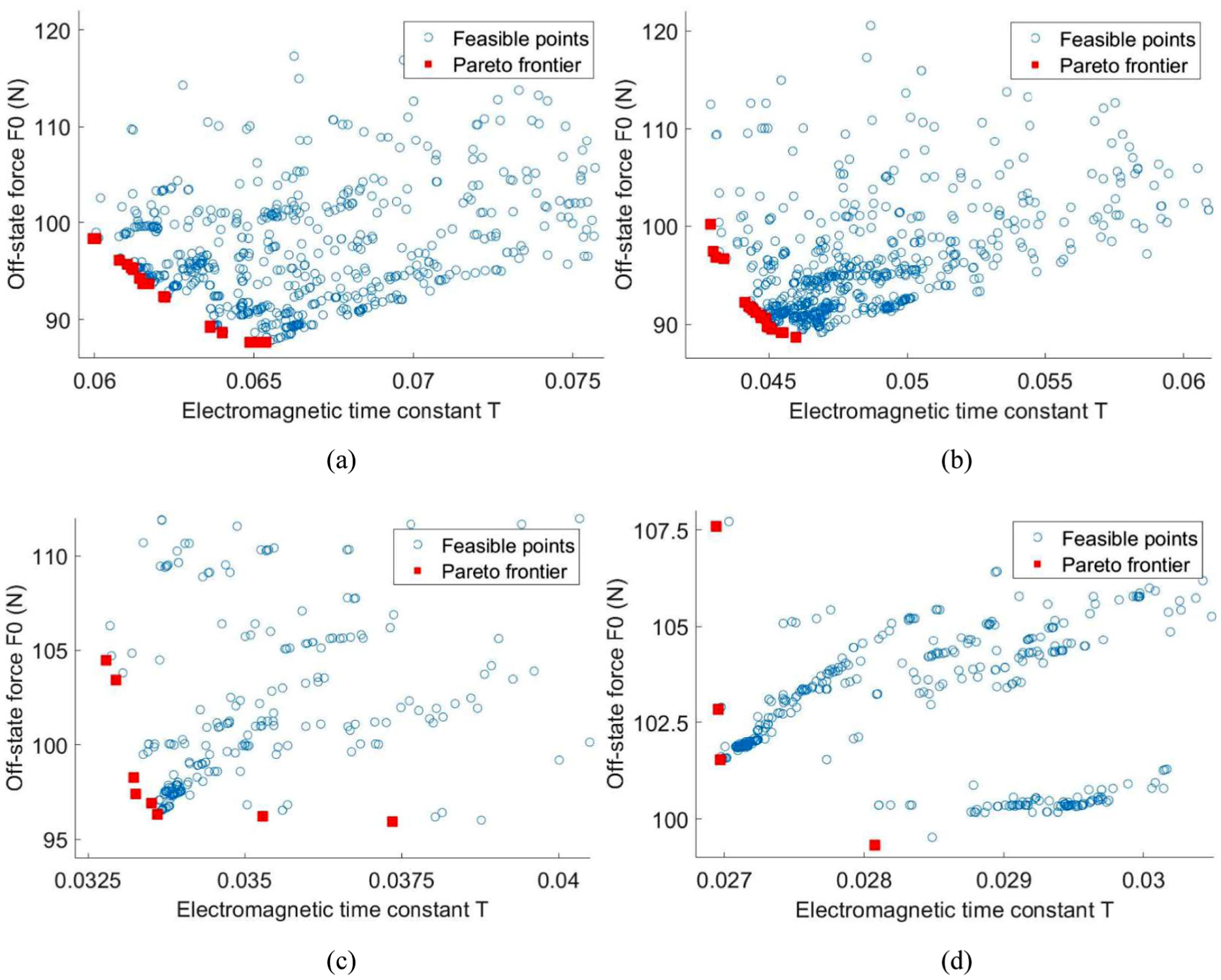
Pareto front charts generated for different configurations of the shear-mode twin-tube MRID: (a) Nz = 3, (b) Nz = 4, (c) Nz = 5, and (d) Nz = 6.
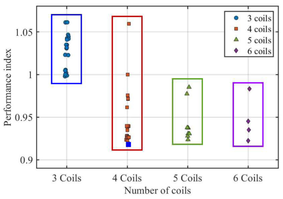
Performance indices of the Pareto candidate solutions for the four MRID configurations.
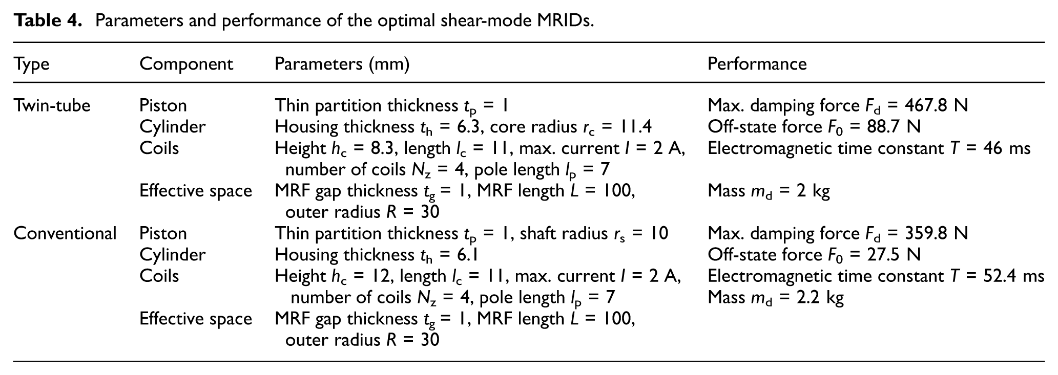
Table 4 summarizes the parameters and performance of the optimal shear-mode twin-tube MRID with Nz = 4 (weighting set 0.7/0.3). To demonstrate the superiority of the proposed twin-tube shear-mode concept, the optimal solution of a conventional single-tube shear-mode MRID is also included for comparison. It is worth noting that, within the same confined effective space, the conventional configuration produces a maximum damping force of 377.3 N, which falls short of the required 467 N, whereas the twin-tube MRID satisfies this constraint. This comparison clearly demonstrates the superior damping capability and compactness of the proposed design. However, this improvement is accompanied by an increase in off-state force (88.7 N vs 27.5 N), indicating a trade-off between load capacity and baseline resistance. For the present shear-mode configuration, the viscous contribution to the off-state force is relatively small, accounting for approximately 13% based on simulation results. The dominant contribution arises from the seal friction due to the increased number of O-rings in the twin-tube configuration compared to the conventional design. This structural feature primarily leads to the higher baseline friction force. Additional variations due to manufacturing tolerances may exist but are considered secondary relative to the systematic increase associated with the sealing design. From an application perspective, the elevated off-state force remains acceptable for the intended impact mitigation scenario. Under impact loading, the damper operates in a high-force regime where the relative contribution of the off-state force is small compared to the peak force capacity. Moreover, a certain level of baseline resistance may help suppress initial free motion and contribute to early-stage energy dissipation. The higher off-state force also provides an inherent fail-safe characteristic, ensuring a minimum level of damping even in the event of power supply or control system failure. Therefore, the observed trade-off is considered acceptable, as the proposed design fulfills the required load capacity while maintaining a manageable increase in passive resistance. Figure 7 further illustrates the magnetic flux density distributions at the optimal conditions for the two shear-mode MRIDs. It can be observed that the twin-tube configuration utilizes the magnetic field more effectively within the constrained space, enabling a larger volume of MRF to be activated and thereby leading to a substantial improvement in overall performance.
Parameters and performance of the optimal shear-mode MRIDs.
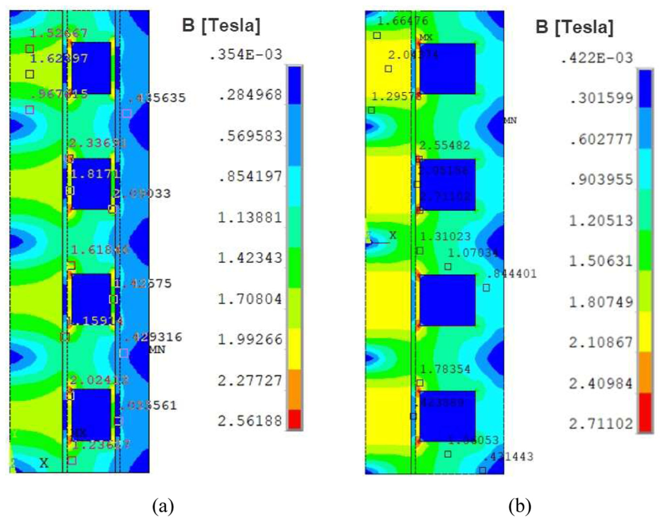
Magnetic flux density B distributions of the optimal shear-mode MRIDs: (a) twin-tube configuration and (b) conventional single-tube.
Experimental evaluation
Guided by the optimal configuration derived in Section 4, the proposed twin-tube shear-mode MRID with Nz = 4 is developed and fabricated for experimental evaluation. Figure 8 displays the prototype assembly along with its primary mechanical components. All parts were CNC-machined for high dimensional precision, followed by careful manual assembly to guarantee proper alignment and sealing integrity. No significant MRF leakage was observed during the tests, while any residual air entrapment was maintained at a minimal level and did not noticeably affect the measured responses.
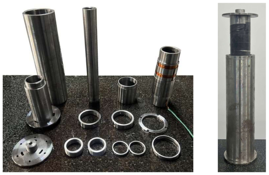
Prototype of the optimized twin-tube shear-mode MRID with Nz = 4.
Figure 9 illustrates the experimental platform used to characterize the damping behavior of the MRID prototype. In this setup, a linear actuator transforms the motor’s rotational motion into linear motion to drive the piston. A dedicated power supply delivers the required current to energize the MRID coils. The piston displacement and generated damping force are monitored by a linear variable differential transformer (LVDT) and a load cell, respectively. The sensor outputs are conditioned, digitized via a data-acquisition (DAQ) module, and transferred to a computer for data logging and further analysis. It is noted that to reduce the noise and uncertainty effect for better measurement consistency, the experiments are repeated five times under identical conditions and the average values are used in the following figures.
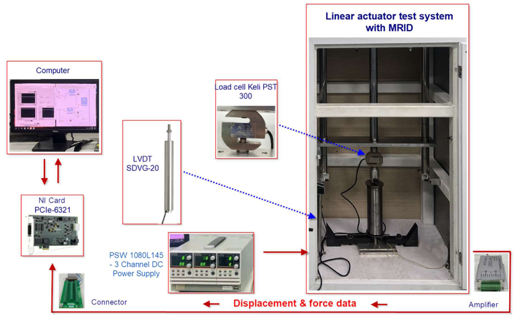
Experimental platform to evaluate damping force performance.
Figure 10 presents the experimental response of the MRID prototype under a cyclic excitation at 1 Hz frequency for coil currents from 0 to 2.5 A (0.25 A increments). Results predicted by the quasi-static model developed in Section 3 are included for reference. Overall, the measured responses correlate well with the model. At steady state, the experimentally measured off-state force is approximately 13.8% higher than the modeled value (see Figure 10(c)). This discrepancy is primarily attributed to uncertainties in Coulomb friction, arising from manufacturing tolerances of coaxial components and from the theoretical underestimation of piston–O-ring friction. As the coil current increases, the field-dependent yield force becomes dominant and the relative difference between experiment and model diminishes. However, beyond about 0.75 A, unmodeled magnetic losses and flux leakage in the practical magnetic circuit cause the experimentally obtained damping force to fall below the predicted values by roughly 3.4%. Measurement noise and small alignment errors may also contribute to the remaining deviation. Furthermore, the experimental results indicate that the damping force approaches saturation when the coil current reaches approximately 2 A. Increasing the current further to 2.25 and 2.5 A does not produce a noticeable increase in the measured damping force, with the average change for each increment remaining within about 1.2%. This response suggests that the magnetic circuit is approaching its effective saturation limit, beyond which additional current provides negligible improvement in controllable force while inevitably increasing power consumption and heat emission in the excitation coils. It should be noted that the present results are obtained from short-duration tests, and thermal effects associated with prolonged high-current operation are not considered.
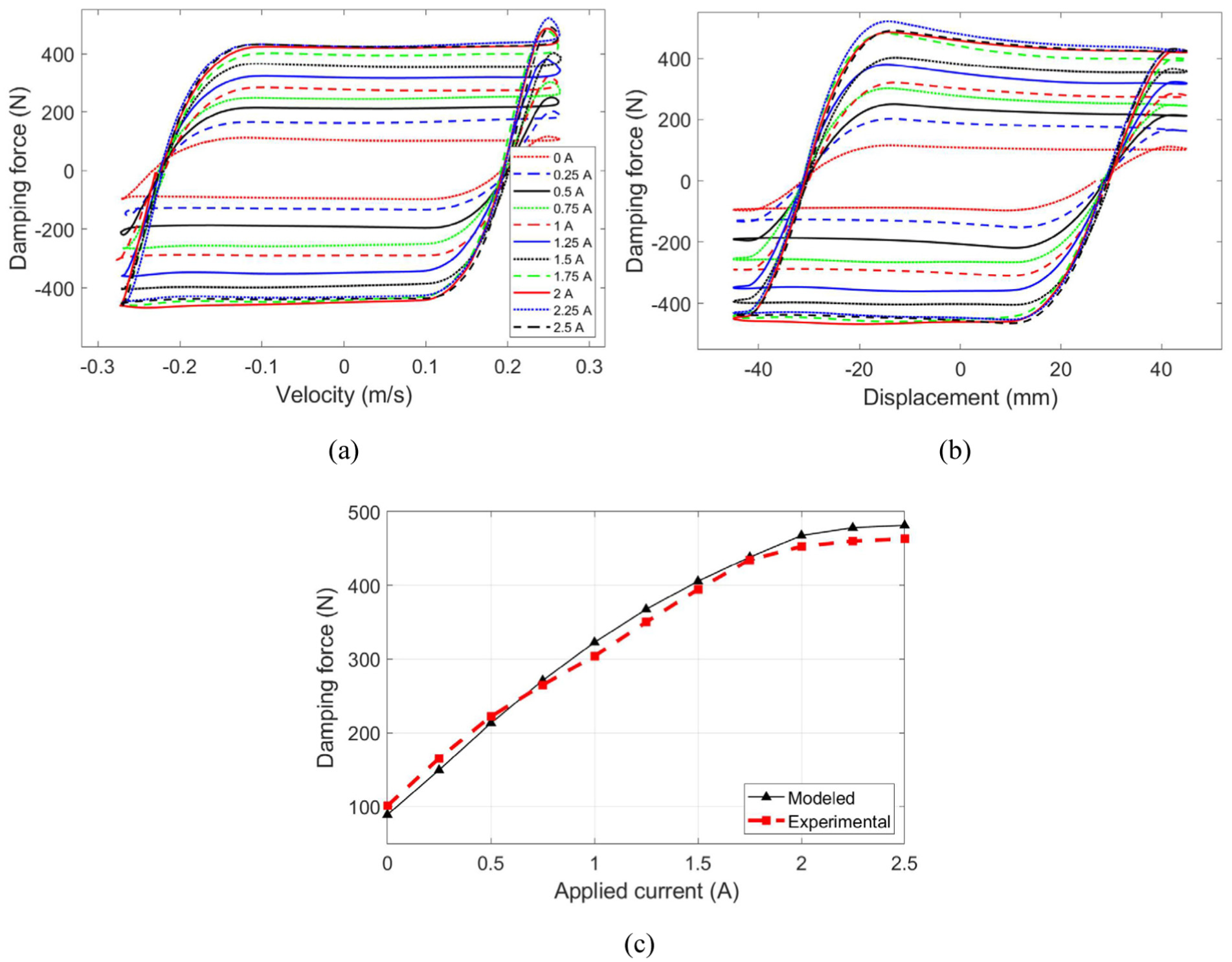
Experimental damping performance of the MRID prototype under a frequency of 1 Hz and currents of 0–2.5 A (0.25 A increments): (a) force versus velocity, (b) force versus displacement, and (c) steady peak force versus current.
Turning attention to the damping force–velocity characteristics of the MRID prototype under cyclic excitation in Figure 10(a), the responses clearly exhibit a pronounced hysteretic behavior, evidenced by well-defined closed loops generated from distinct force trajectories during the forward and return strokes. For a given velocity, the force does not retrace the same path between acceleration and deceleration, reflecting path dependence and memory effects characteristic of hysteresis. Specifically, this hysteresis originates from the delayed structural response of the MRF. During cyclic motion, magnetic field-induced particle chains deform, break, and reform, causing the internal shear stress to lag behind velocity changes and generating different force trajectories in the forward and return strokes. The width of the hysteresis loop represents the magnitude of this delay and the amount of the mechanical energy dissipated per cycle. As the excitation current increases, both the peak force and loop area expand monotonically, confirming that the applied magnetic field effectively augments the yield force and enhances the device’s energy dissipation capability, with more pronounced hysteresis. The smooth loop profile also indicates that the hysteresis mainly arises from rheological processes within the MRF rather than discrete mechanical friction. The loop shape remains largely rectangular at low velocities, characterized by an approximately constant force level in both loading directions. This behavior indicates that the response is dominated by a rate-independent yield stress component, analogous to Coulomb-type friction. Quantitatively, the plateau force corresponds to the field-dependent yield shear stress of the MRF integrated over the effective shear area of the annular gap. As velocity increases, a gradual slope appears in the force–velocity relation, reflecting an additional velocity-dependent term consistent with Bingham-type damping. Because the bottom cavity is vented, the internal gas pressure remains close to ambient pressure. Therefore, the observed velocity dependence originates predominantly from the intrinsic post-yield viscous behavior of the MRF rather than pneumatic compression effects. However, the small-slope linear regression of the high-velocity region shows that the viscous contribution is secondary relative to the yield force, demonstrating the low velocity sensitivity achieved by the proposed design within the tested velocity range. Mild asymmetry between positive and negative strokes is also observed, likely attributable to non-idealities and preload effects inherent to the device structure.
To investigate the influence of excitation rate on the damping performance, the MRID prototype was tested at elevated frequencies. As shown in Figure 11, the damping force–velocity loops retain the characteristic shear-mode behavior, with the overall response governed predominantly by field-controlled shear yield rather than strong flow-induced viscous effects typical of flow-mode MRIDs. While the force–velocity slopes are only marginally steeper than those at low frequency, the loop width and curvature increase slightly at higher piston speeds, indicating a modest rate-dependent contribution superposed on the rate-independent yield. Correspondingly, the steady peak forces show mild increases of approximately 3.5% and 8% at 5 and 10 Hz, respectively, relative to the low-frequency data, which further confirms the inherently low velocity sensitivity of the shear-mode configuration. The incremental growth in loop area with frequency therefore arises mainly from larger attainable velocities acting against an essentially constant yield-dominated resistance, and may also reflect additional mechanisms including viscous drag, inertial effects, and transient magnetic diffusion in the practical device. The force–velocity responses also exhibit small backward hysteresis loops near the extremities of the curves, which are attributed to the combined effects of the intrinsic response lag of the MRF and the pneumatic dynamics associated with the air cavity. In the proposed twin-tube MRID, the MRF operates predominantly in shear mode with negligible bulk flow, and the damping force is governed by the field-dependent yield stress. However, the evolution of yield stress does not instantaneously follow the applied magnetic field, introducing a finite response lag. In addition, the vented air cavity at the piston end forms a compressible subsystem in which pressure equalization is delayed. The interaction of these mechanisms leads to a transient mismatch between piston velocity and damping force, resulting in local non-monotonic behavior and the formation of backward loops.
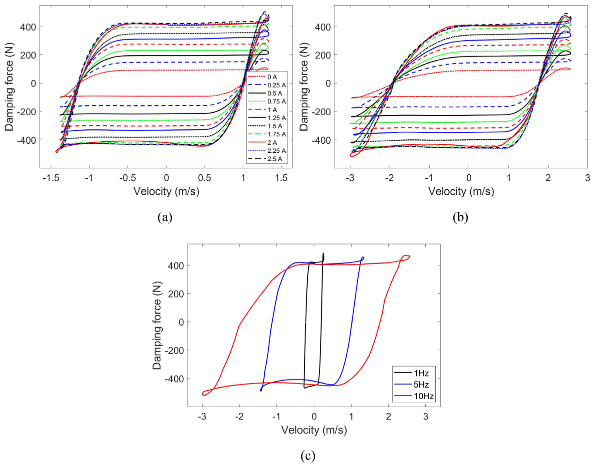
Experimental damping performance of the MRID prototype under higher frequencies: (a) 5 Hz frequency and 0–2.5 A currents, (b) 10 Hz frequency and 0–2.5 A currents, and (c) 2 A current and different frequencies.
Following the damping performance evaluation under cyclic excitations, the shock-mitigation capability of the proposed shear-mode twin-tube MRID under real impact scenarios is examined. The experimental configuration for the drop-weight tests is shown in Figure 12. The setup consists of a guided drop mass, an impact plate, and vertical guide columns. Beneath the plate, a suspension system integrating the MRID prototype with a spring is rigidly anchored to the foundation to absorb and control the impact input. A mechanical release mechanism is employed to drop a 10 kg mass from a height of 1 m, enabling direct engagement with the MRID system upon impact. The tests are conducted at different constant coil currents, supplied by the power unit, to assess the field-dependent mitigation performance. For each current level, the resultant force–time and displacement–time histories are recorded for post-processing to evaluate the overall attenuation effectiveness.
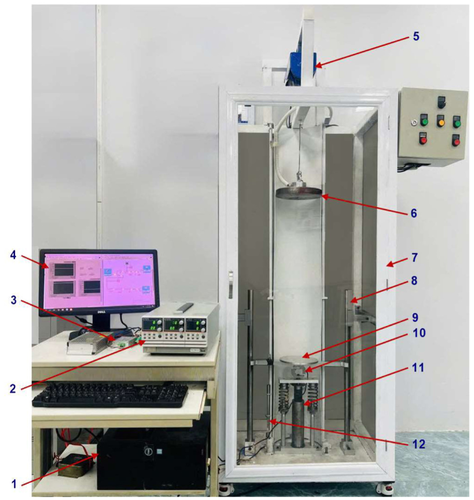
Experimental drop-test setup to evaluate impact mitigation performance. (1) DAQ-integrated computer, (2) power supply, (3) amplifier, (4) monitor, (5) drop mechanism, (6) drop mass, (7) drop-test frame, (8) guide column, (9) impact plate, (10) force sensor, (11) MRID prototype, (12) LVDT.
Figure 13 presents the measured force–time and displacement–time histories of the MRID in the off-state and at 2 A excitation current. The impact events are initiated at 1 s, followed by oscillatory relaxation of the damped mass–spring suspension system. As shown in Figure 13(a), the residual and peak piston displacement decreases significantly when the current is applied. In the zero-field case, the mass penetrates deeper into the MRID–spring system, whereas the activated state more effectively limits motion, indicating enhanced arresting capability. Conversely, the transmitted force histories in Figure 13(b) show that the magnitude of the initial compression peak increases under excitation. This higher resistive force corresponds to a more rapid deceleration of the impacting mass and an increased rate of energy dissipation during the initial compression stroke. As a result, a larger portion of the impact energy is dissipated within the MRF, rather than being stored elastically in the suspension or manifested as prolonged oscillatory motion. However, the excitation also leads to a higher instantaneous transmitted force, which may elevate the load experienced by occupants or protected structures. Therefore, achieving optimal impact mitigation requires an appropriate control strategy that balances peak force limitation and energy absorption. Overall, these findings demonstrate the rate-insensitive damping performance and effective impact mitigation capability of the proposed compact twin-tube shear-mode MRID.
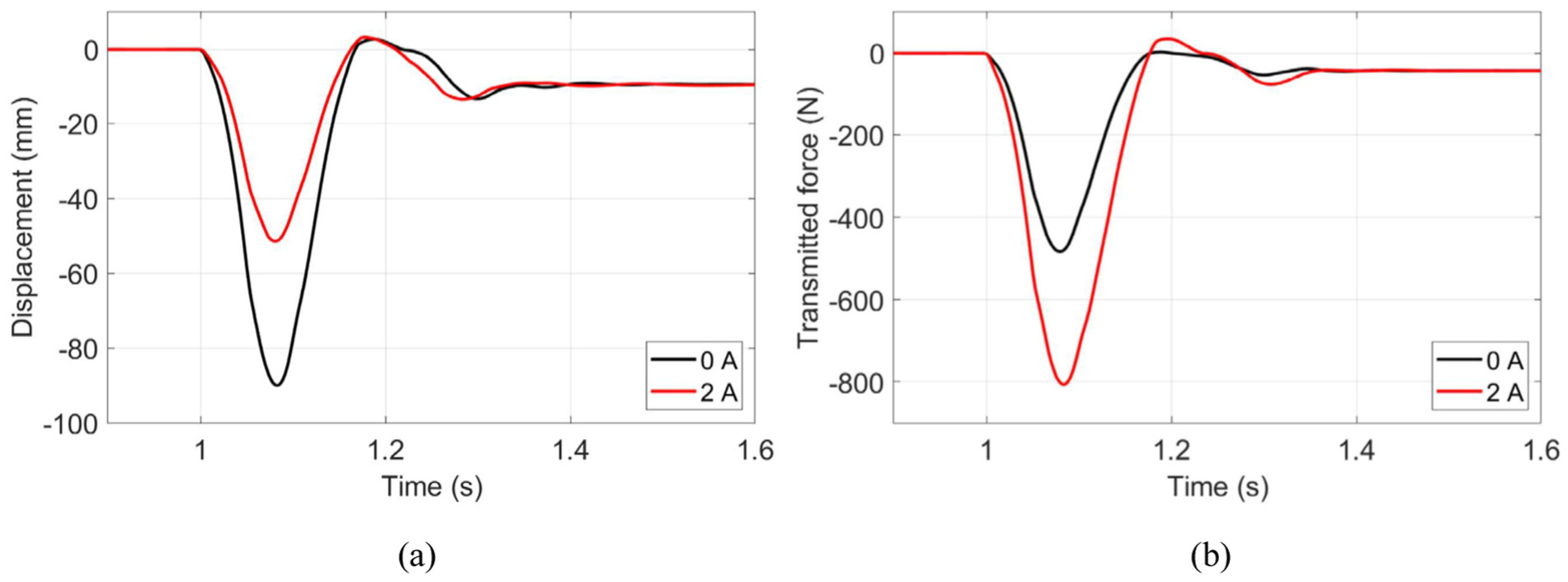
Measured force–time and displacement–time histories for different coil currents under impact: (a) displacement versus time and (b) force versus time.
In summary, the proposed model is validated primarily under cyclic excitation conditions, where experimentally measured results at 1, 5, and 10 Hz with input currents from 0 to 2.5 A show good agreement with the predicted responses. The proposed shear-mode twin-tube MRID is designed for a maximum operating current of 2 A, and the experimental results indicate the onset of magnetic saturation at higher currents (2.25 and 2.5 A), suggesting that the near-saturation regime is partially captured within the validation range. For transient impact conditions, the model is applied to interpret the drop-induced responses. However, due to the highly dynamic nature of impact loading and the limited number of test cases, the corresponding results should be considered approximate. Therefore, the model is well validated for quasi-steady cyclic operation, while its predictions under impact loading should be interpreted with caution.
Conclusions
This study introduced a novel shear-mode twin-tube magnetorheological impact damper (MRID) designed for compact and tunable impact mitigation. The design concept was rigorously developed and validated via quasi-static modeling, performance-index-driven optimization, and experimental testing of a prototype. Compared to a conventional single-tube shear configuration, the twin-tube architecture enlarges the effective shear-activated magnetorheological fluid region within a constrained volume, achieving a superior field-dependent damping capacity. Cyclic experimental tests validated the modeling framework, revealing yield-dominated hysteresis with low velocity sensitivity. Minor discrepancies between model predictions and measured responses were originated from magnetic leakage, seal friction, and machining tolerances. High-frequency excitation tests further demonstrated that the damper maintains stable, yield-dominated hysteretic behavior, with only modest increases in hysteresis loop width and peak force as frequency rises. This limited force enhancement underscores the design’s inherently low velocity sensitivity; additional energy dissipation at higher rates is primarily due to greater attainable velocities, alongside minor viscous, inertial, and transient magnetic effects. Subsequent drop-impact experiments also confirm that energizing the MRID enhances motion arrest and energy dissipation capability, albeit with an accompanying increase in instantaneous transmitted force, highlighting the need of an appropriate control strategy to balance effective impact attenuation with acceptable peak load levels. In overall, the proposed twin-tube shear-mode MRID offers a compelling combination of compactness, load capacity, controllability, and applicability. This work provides a foundation for future advanced research in areas such as closed-loop control, refined magnetic-loss modeling, and long-term durability assessment. Our next research phase will focus on expanding the range of impact conditions, quantifying key performance metrics, investigating current sensitivity, and establishing a more complete impact-performance map for the proposed device.
Footnotes

Funding
The authors disclosed receipt of the following financial support for the research, authorship, and/or publication of this article: This research is funded by Vietnam National Foundation for Science and Technology Development (NAFOSTED) under grant number 107.03-2023.86.
Declaration of conflicting interests
The authors declared no potential conflicts of interest with respect to the research, authorship, and/or publication of this article.
Data availability statement
All data that support the findings of this study are included within the article (and any supplementary files).