






Abstract
Sedimentation of carbonyl iron microparticles (CIP) in magnetorheological (MR) fluids is an inherent phenomenon driven by the density difference between the fluid’s phases. In rotary MR clutches, the high centrifugal accelerations substantially amplify this effect, specifically for power transmission applications where accelerations are held for long durations. The mechanics describing the segregation of CIP from MR fluid under high acceleration fields in hundreds of g is yet unknown. To describe the phenomenon, this paper proposes a mathematical description of the motion of the CIP under centrifugal acceleration and verifies model predictions with experiments. The model is based on the theory of kinematic waves for centrifugal acceleration, here adapted for MR fluid. Centrifugation tests are performed in a LUMiSizer centrifuge using a MR fluid formulation without typical additives. The fluid has a particle concentration of 37% v/v, which is typical for clutch applications. Results show that the model accurately predict particle dynamic above 60g and up to 2325g. Below this threshold, discrepancies emerge, mostly attributed to the thixotropic properties of MRF and the determination of the flux function. These results show that kinematic waves theory captures the key mechanisms of MR fluid centrifugation for the tested formulation, while highlighting the need for further work to extend its applicability to a broader range of MR fluids with different particle concentration, size distribution and additive packages.
Introduction
Motivation
Magnetorheological (MR) actuators are a motion control solution for applications requiring high torque density, high torque controllability and backdrivability (Plante et al., 2025). The distinctive feature of MR actuators is the presence of a torque-controllable MR fluid clutch, strategically placed between the motor and the actuator’s output. Contrary to conventional clutches, MR clutches have no mechanical contacts. Instead, a thin annular gap is filled with magnetorheological fluid (MRF), a suspension of carbonyl iron micro particles (CIP) mixed in a non-magnetic carrier fluid. When subjected to a magnetic field, CIP align along the magnetic flux lines to form chains, modifying the apparent viscosity of the fluid under shear (Rabinow, 1948). MR clutches in actuator applications perform two key functions: (1) control the torque output electrically with precision and reactivness by an electro-magnet and (2), decouple the motor inertia from actuator output, providing low actuator inertia and low backdriving forces.
Most MR clutches applications proposed so far have been for robotics and vibration control applications (RVCA), where operating conditions are constantly varying in time as in a transient regime (Bira et al., 2022; Bucchi et al., 2014; Chen et al., 2019, 2022; East et al., 2021; Fauteux et al., 2010; Kikuchi et al., 2010; Mallette et al., 2023; Moghani and Kermani, 2016; Ning et al., 2020; Pisetskiy and Kermani, 2020; Plante et al., 2025; Shafer and Kermani, 2011, 2014; Viau et al., 2017). MR clutches have also been investigated for power transmission applications (PTA), where operating conditions are mostly static in time, being either locked or unlocked, as in a steady state regime (Kieburg et al., 2007; Lo Sciuto et al., 2023; Neelakantan and Washington, 2005; Park et al., 2022, 2024; Singh and Sarkar, 2023; Wu et al., 2019, 2025; Zhang et al., 2019a). Table 1 compares both operating conditions of RVCA and PTA.
Order of magnitude of the differences in operating conditions between RVCA and PTA.
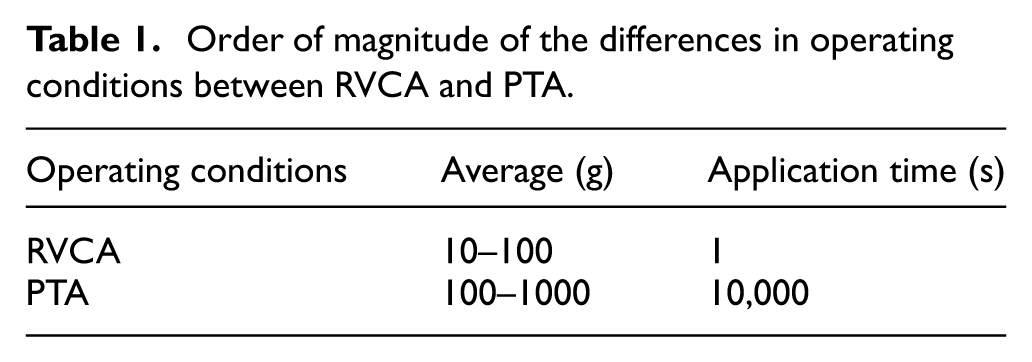
Centrifugal sedimentation in RVCA has not been observed so far. However, PTA have significantly higher rotational speeds held for significantly longer time. Those conditions are akin to centrifuge machines (Neelakantan and Washington, 2005) and can cause centrifugal sedimentation, where the CIP will eventually separate from the carrier fluid if held for sufficient time, as illustrated in Figure 1.
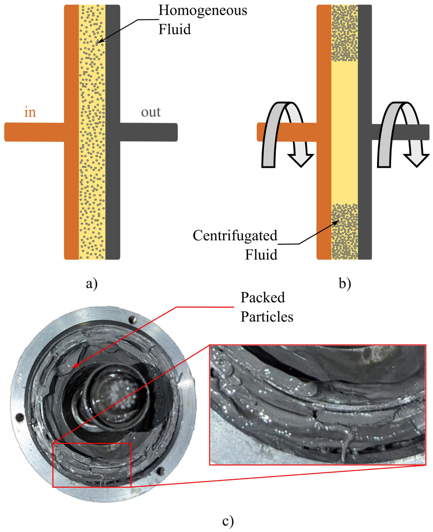
Clutch cross-section schematic of centrifugation: (a) before high speed rotation and centrifugation, (b) after or during centrifugation, and (c) packed particles in a centrifugated MR clutch.
Background
Neelakantan and Washington (2005) had already highlighted the issue of centrifugation for MR clutch. To solve this issue, they proposed to use MR foam instead of MRF, the open-cell polyurethane trapping particles and preventing sedimentation. They tested the prototype and showed that the foam was able to limit the CIP migration. They however kept their testing to small rotational speed, stating that “removing the problem of centrifuging at high rotational speeds is to be confirmed” (Neelakantan and Washington, 2005). They also highlighted that a method to track particle velocity in the centrifugal field is needed.
Zhang et al. work has also accounted for the centrifugal effect on MRF (Zhang et al., 2019b; Zhang and Lu, 2018). They described a torque estimation model accounting for the impact of the centrifugal effect. As the present study concentrates on describing the particles motion, which implies no magnetic field, this approach is discarded.
Finally, Güth and Maas showed that it was possible to use Taylor vortices to induce turbulence in the fluid at really high rotational speed (34,000
To date, there is no model in the literature that predict the motion of CIP during centrifugal sedimentation of MRF. By contrast, lots of work has been published regarding gravitational sedimentation of MRF. A model that presented good agreement with experimental measurement was the kinematic waves theory based on Kynch’s work (Kynch, 1952) and adapted for MRF by Choi et al. (2016), to study fluid sedimentation in MRF-based device used infrequently. The theory of kinematic waves has also been validated for the centrifugation of non-MR suspensions such as red blood cells (RBC; Frömer and Lerche, 2002).
Approach
The objective of this paper is to conduct a first mathematical description of the particle motion during centrifugal sedimentation in MR fluids. To do so, an extensive experimental characterization of MRF is first conducted with a centrifuge machine and one-dimensional sample vials, to build a reliable dataset. Then, a sedimentation model based on kinematic waves theory is derived and used to predict sedimentation under various acceleration fields. Finally, results are compared to experiments and model performance is discussed.
Experimental
This section presents the properties of the tested MRF and those of the centrifuge apparatus setup as well as typical measurements obtained in operation.
Fluid
The test fluid is specifically formulated for this study, without typical additives like anti-wear, dispersant or viscosity modifier. The reason is to simplify the problem by eliminating the additives’ effects on the rheology, which is left for future work. Therefore, more tests with different formulations (CIP concentrations, size distribution and additive packages) will be required to show a broader applicability of the mathematical description that is presented later in Section ‘Analytical development’. The MRF still contained minimal traces of dispersant to facilitate the process of remixing prior to each test, which ensures repeatability between experiments.
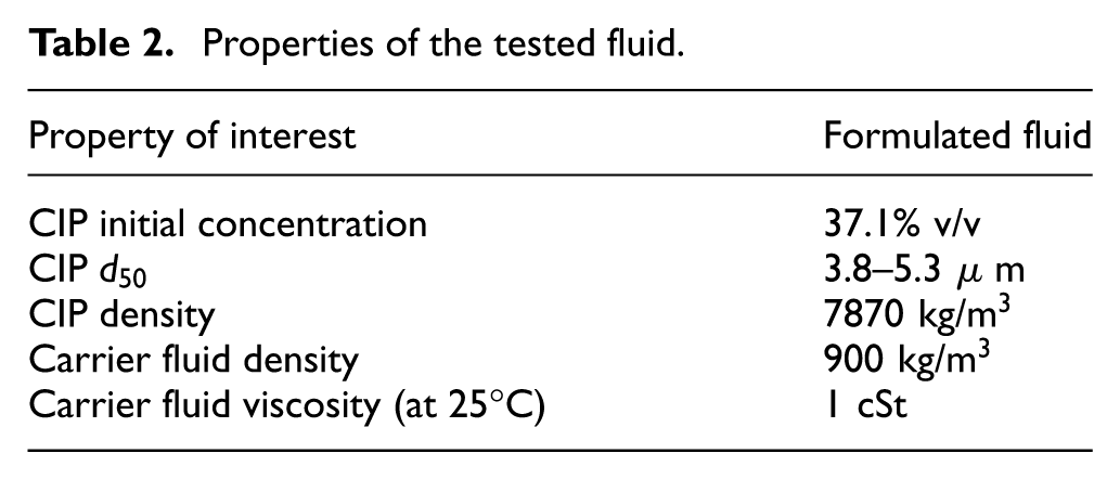
Properties of the MRF are presented in Table 2. A concentration of CIP of 37.1% v/v is chosen, which is typical for MR clutch applications. The particle size distribution is characterized by a median diameter
Properties of the tested fluid.
Centrifuge
A LUMiSizer® (LUM GmbH, n.d) dispersion analyzer, which is an analytical centrifuge equipped with a light transmission sensor, is used to centrifuge the MRF. During a measurement, light rays are sent through the entire height of fluid while the samples are rotating at a constant speed. In the suspension, particle locally obstruct the light from reaching the receptor on the other side of the translucid vial. The carrier fluid, on the contrary, is translucid and let the light through. The local light transmittance levels are attributed to different concentration of particles and are assembled into a profile of light transmission for the whole height of fluid. This profile is measured at each desired time stamps over the centrifugation period. The measuring mechanism is illustrated by Figure 2. Specifications of interest for the LUMiSizer are presented in Table 3.
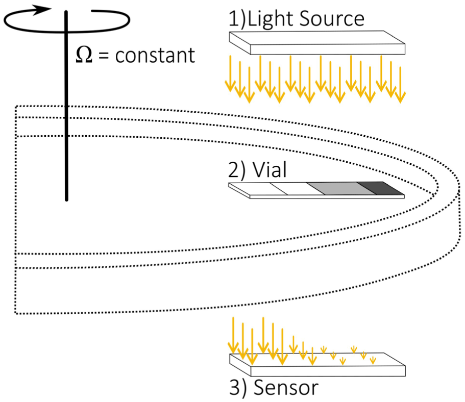
LUMiSizer® measuring mechanism.
LUMiSizer’s specification (from LUM GmbH, n.d).
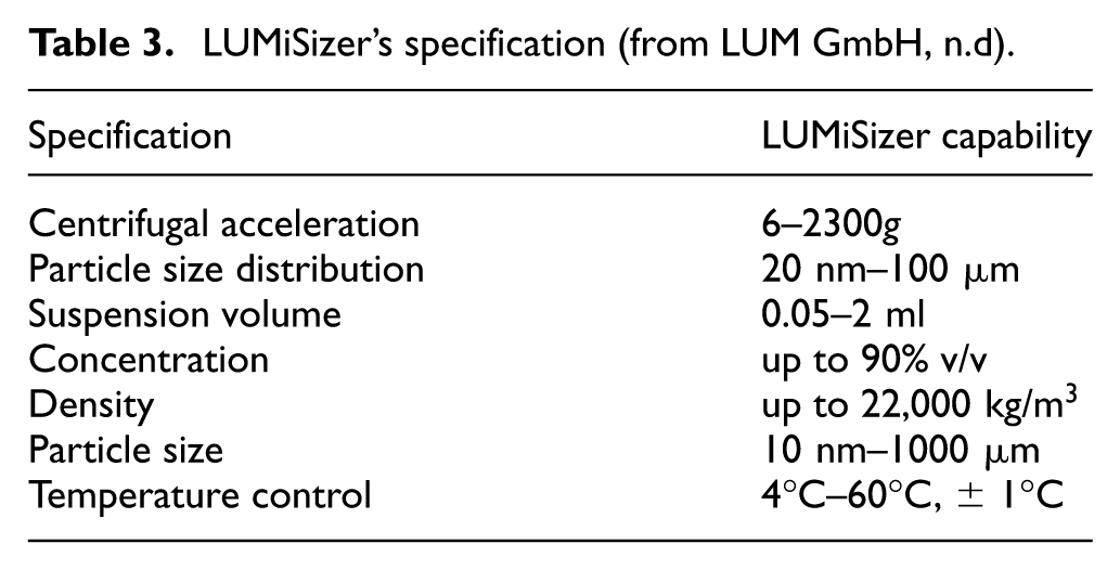
The LUMiSizer testing capabilities are suitable for MRF, as the fluid properties presented in Table 2 are all within the centrifuge specification ranges. Tests conditions are as follows:
2 ml is poured in three different LUMiSizer vials to ensure repeatability of the data.
The dimensions of the vials are 3 × 8.5 mm for the rectangular base, filed up to approximately 20 mm of MRF.
Test periods of 250 min, making sure that steady state is reached and the concentration profile are stable.
The temperature is kept constant at 25°C throughout the test.
Typical test results along with a picture of a sample vial with the centrifugated MRF is presented at Figure 3. The light transmittance measurements are presented by solid lines with a color gradient from red to green, respectively for the beginning and the end of the test, with 30 s between each measurement. A dip in light transmittance is found at approximately 108 mm. It is caused by the meniscus of fluid. It marks the position of the top of the fluid height, and is indicated by a first red dashed line. The second red dash line marks the bottom of the vial. Over the course of the experiment, the sedimentation front, indicated by the blue dashed line, progressively descends toward the bottom of the vial. This is shown on Figure 3(a)) by the progression of the solid red lines to the right. On Figure 3(b)), the clear yellow phase is attributed to around 50% of light transmittance while the particles block the light and has a value of 0%.
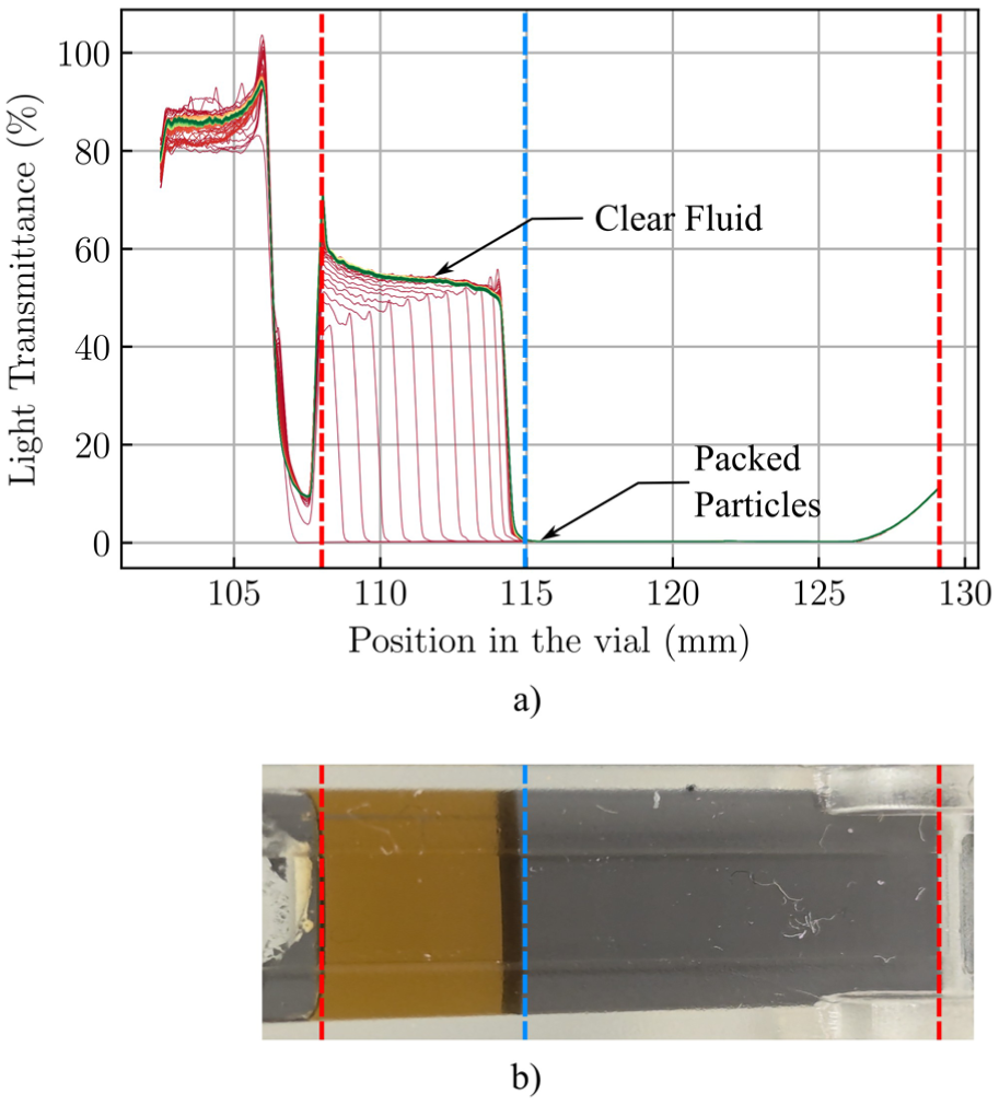
Outcome of a LUMiSizer test: (a) typical results for light transmittance and (b) centrifugated vial of MRF.
The first value of 0% of light transmittance is tracked over each profile, as it corresponds to the sedimentation front. Its evolution over time is presented at Figure 4. Results range from 40 to 500g. Measurements above 500g are almost identical and are not shown for clarity. The y-axis is kept non-dimensional in order to compare all the measurement with a fixed reference frame, as the total height of fluid vary with the exact volume of fluid poured in the vial. Arbitrary value of one is attributed to the top of the fluid height and two for the bottom of the vial, as in Lueptow and Hübler (1991).
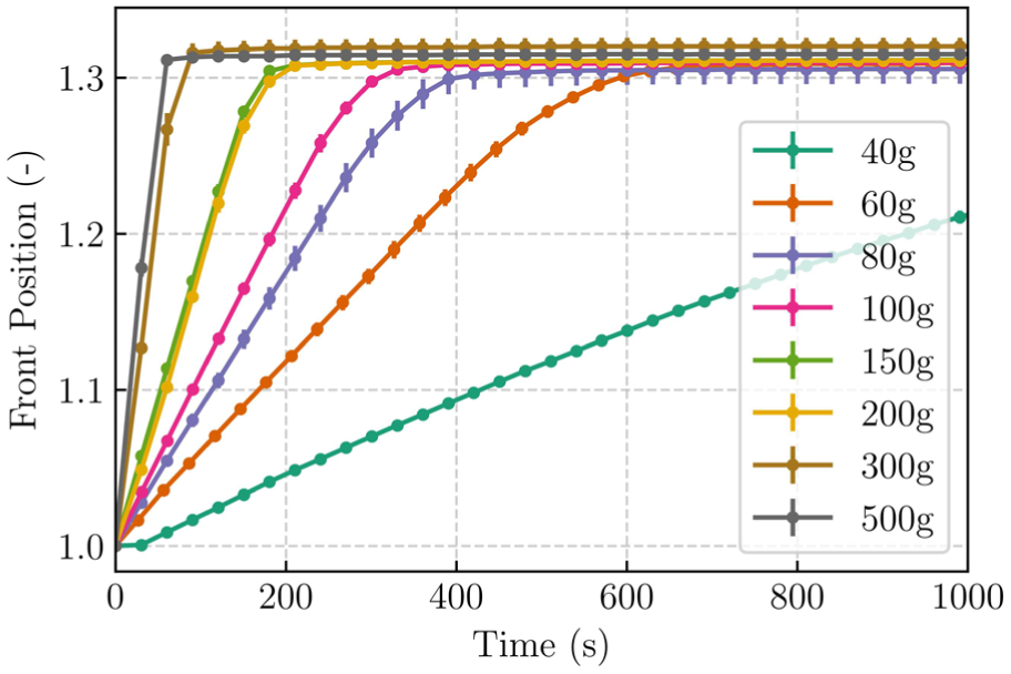
Progression of the sedimentation front from 40 to 500g.
For all tested acceleration, the maximal concentration reached in the packed particles after centrifugation is around 54% v/v. It corresponds to a final position of 1.32 for an initial concentration of 37%v/v. This is consistent with the literature, which says that for solid particles, maximal concentration from 50% to 74% v/v have been observed. This deviation from the theoretical maximal value of 72% v/v for polydispersed particles is caused by “the arrangement of particles and presence of lubrification forces which tend to sustain non-zero gaps” (Ungarish, 1993).
All points also have their error bars, calculated with the three samples for the position of the front, mainly visible for the 80g case. The maximal standard deviation for all points was 1%.
Analytical development
Particle concentrations in MRFs used for clutch applications are typically high (around 40% v/v), to maximize torque density. In such heavily loaded fluids, particle-particle interactions are significant, as they become non-negligible above 5% v/v (Holdich, 2002). Sedimentation models accounting for particle-particle interactions are referred to as hindered settling. Since each particle obstructs its neighbors from reaching their individual free settling velocity, the suspension settles at a slower velocity than an isolated particle. Hindered settling is characterized by a piston-like settling motion with the formation of clear interfaces between zones of distinct concentrations. This is presented by Figure 5, with phases A, B, C and D (Lueptow and Hübler, 1991).
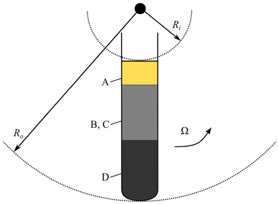
Hindered settling in a centrifuge.
Because of the hindering effect, particles located near the top of the suspension will always rejoin the settling front. This generates a growing region of clear fluid atop the suspension, referred to as the supernatant or the clear fluid (A). Immediately below lies the region of sedimenting particles (B), in which the particles settle collectively at an approximately uniform velocity, concentration being approximately uniform. As sedimentation progresses, particles accumulate at the bottom of the container, forming a packed layer of stationary particles. This layer is known as the hard cake or the packed particles (D). Finally, an intermediate region develops between the sedimenting zone and the hard cake. Called the accumulating particles (C), it contains particles whose concentration increases progressively as they approach the packed bed. The increased concentration in this region enhances particle-particle hindrance, leading to a progressive deceleration of the settling process until particles are stationary in the hard cake. As there is no discontinuity between the sedimenting particles and the accumulating particles, both region merging after some time, they are represented as a continuous region.
Kinematic waves theory
Kynch (1952) considered hindered settling for gravitational acceleration. Anestis and Schneider (1983) adapted the model for centrifugal acceleration with the kinematic waves theory. In this theory, the continuous gradient of particle concentration in a zone corresponds to waves and the discontinuity between zones corresponds to shocks. The kinematic waves theory is based on two fundamental assumptions:
The concentration of a suspension is constant along a horizontal cross-section of the container, making the model one dimensional.
The only parameter affecting the speed of a particle is the local concentration of particles.
Lerche and Frömer showed that the one-dimensional assumption was valid in their studied case, as there was good agreement between experiment and theory for centrifugation of RBC (Frömer and Lerche, 2002; Lerche and Frömer, 2001).
The modeling framework proposed in this paper consists of: an incompressible fluid that has a density

where

From the characteristic speed is calculated the characteristic time of the system

This system is the basic framework on which is applied the kinematic waves theory. It starts by expressing the continuity equation for particles in terms of concentration

stipulating that the variation of concentration in the container over time only depends on the particle flux


where
As centrifugal sedimentation differs from gravitational sedimentation, with a variation of the acceleration along the radius, the assumption that particle velocity only depends on its local concentration is adapted (Lueptow and Hübler, 1991). The particle flux is related to the radial position with

Applying the chain rule, the conservation equation is modified into

The system is finally transferred to the non-dimensional domain for the solution to be applicable to all centrifugal acceleration



with




More detailed discussions on the selection of the boundary conditions and solving methods for characteristic problems can be found elsewhere (Anestis and Schneider, 1983; Lueptow and Hübler, 1991).
Settling flux function
As the fundamental assumption of hindered settling stipulates that the particle settling velocity is only dependent on its local concentration, a function between theses two parameters is essential. With the hindrance being cause by complex particle-particle interaction effects, several empirical or semi-empirical settling velocity function have been used to correct the free settling velocity of a particle by the hindering effect. The most commonly used for MRF (Choi et al., 2016; Zhang et al., 2020) are the Dick and Young (1972), Richardson and Zaki (1954) and Vesilind model (Vesilind, 1968):



where
For the current work, equation (9) from Section ‘Kinematic waves theory’ requires particle flux

It is important to note that this is only applicable for the Vesilind model (equation (13c)) if
The Richardson and Zaki flux function is the model used for the present study, as it is the one commonly used for centrifugal cases (Frömer and Lerche, 2002; Lerche and Frömer, 2001; Ungarish, 1993). Its form for the flux function is adapted using equation (14) on equation (13b)

with

Equation (16) describes the dimensionless viscosity of the suspension, or the increase of the hindering effect caused by the high concentration of particles (Frömer and Lerche, 2002; Ungarish, 1993). The

For MRF, with the CIP being in the micrometer scale, particulate Reynolds number are normally in the viscous regime. In viscous regimes, Richardson and Zaki (1954) indicated an
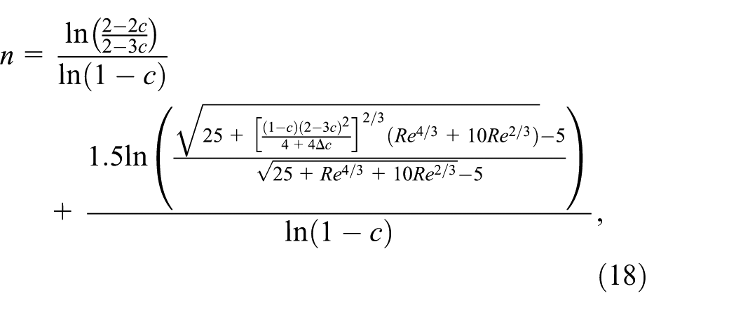
which shows that

The particulate Reynolds number varies with the rotational speed and the particle sizes in the
Variation of
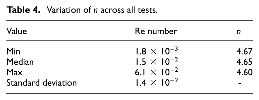
The selected n parameter for the present study is taken from the median value, which is 4.65. The flux function is calculated with equation (15) and presented at Figure 6.
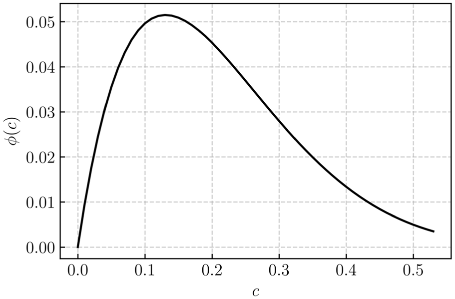
Flux function based on Richardson and Zaki with
It is important to specify that other techniques have been used in the literature to find the empirical constant of the flux function. Since there is only two parameters, a method is to formulate several suspensions with the same chemical components but different concentrations of CIP. The settling velocity is measured for every concentration, each fluid being a datapoint to build the settling velocity function (Choi et al., 2016; Frömer and Lerche, 2002; Zhang et al., 2020).
Results
The resolution of equation (9) in the
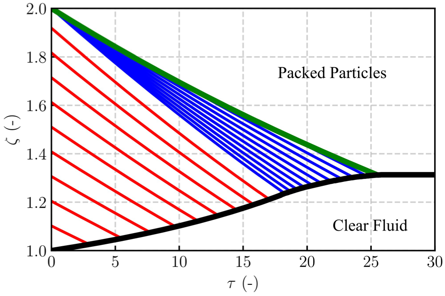
Resolution by the method of characteristics with
In reference to Figure 5, the red characteristics are for the sedimenting particles (B), the blue characteristics are for the accumulating particles (C) and the green characteristics marks the shock to the packed particle region (D). The black line marks the clear fluid shock or the interface between the supernatant (A) and the sedimenting particles.
Figure 8 only shows the Clear Fluid – Sedimenting particles discontinuity progression over time since the other discontinuities are not visible with the LUMiSizer, the particles blocking all the light transmission. To compare model predictions to experimental data, the time axis
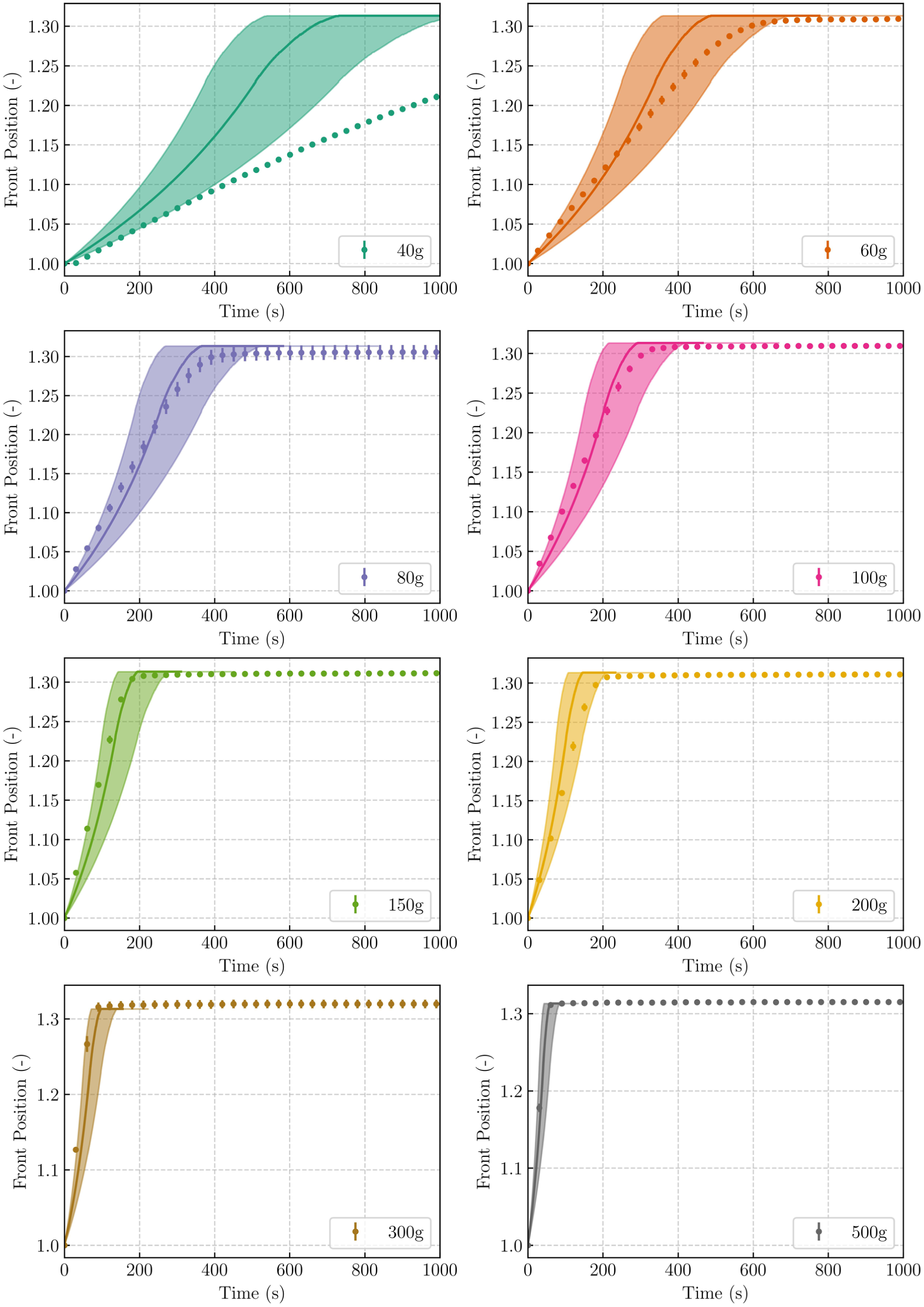
Comparison between experimental measurements and model predictions for centrifugation of MRF from 40–500g.
Figure 9 also shows that the model is valid up to 2325g. According to model predictions, sedimentation should stop after 15 s, which is smaller that the measurement sampling interval. The trend is however really similar, asserting that model predictions is in the good order of magnitude.
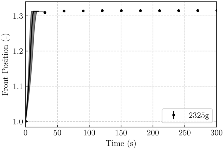
Comparison at 2300g showing the trend is respected.
The model however presents some limitations. First of all, the shaded area seems to narrow as the centrifugal acceleration increases, showing a lesser precision for smaller accelerations. This is mainly due to the wide dispersity of particle sizes in the tested fluid, given by the range of the
Variation of the characteristic time and its impact on the precision of the model.

For smaller centrifugal acceleration, it is also observed that the model is not in agreement with the experiment: data points are outside the shaded area for the 40g test, and they tend to approach the prediction of the median particle radius as the centrifugal acceleration increase. Result from the 40g test with and extended time axis (until measurement reaches steady state) is presented at Figure 10. The best explanation for the discrepancy between model predictions and experimental results is that the flux function from equation (15) is not valid for all ranges of centrifugal acceleration. This can be caused by several physical factors.
One of the main assumption of the model is that the particles are monodispersed and spherical, which is not the case in this study, as it is shown by the
While preparing the fluid and redispersing the particles, it was noted that the fluid exhibited thixotropic properties. This is typical of MRF, which normally exhibits shear-thinning behavior at small shear rates. Their rheology is usually modeled by Bingham plastic or Herschel-Bulkley model (El Wahed and Wang, 2019), both exhibiting decrease of viscosity with initial increase of shear rate. In the hindered settling literature, this non-Newtonian behavior is accounted for by the flux function. The method used to define the flux function in this study seems unable to grasp the strong thixotropy of MR fluids.
In previous usage of the kinematic waves model in the literature, the density difference between the suspension’s phases was not as high as for MRF, which means that the force transmitted to the particles was smaller. This seems to bring a transition akin to the Bingham plastic model, where under a certain threshold, the suspension behave as a viscoplastic. Particle-particle interactions are then highly predominant and the hindering is underestimated by the model. For greater acceleration, order is given to the flow and the sedimentation process is faster. This viscoplastic effect (Balmforth et al., 2014), giving different behaviors across centrifugal acceleration, is to be validated by observing the effect of increasing the centrifugal acceleration on the settling flux function of a suspension.
Another factor is linked to equation (18). The study used to define equation (18) reports and increase of the
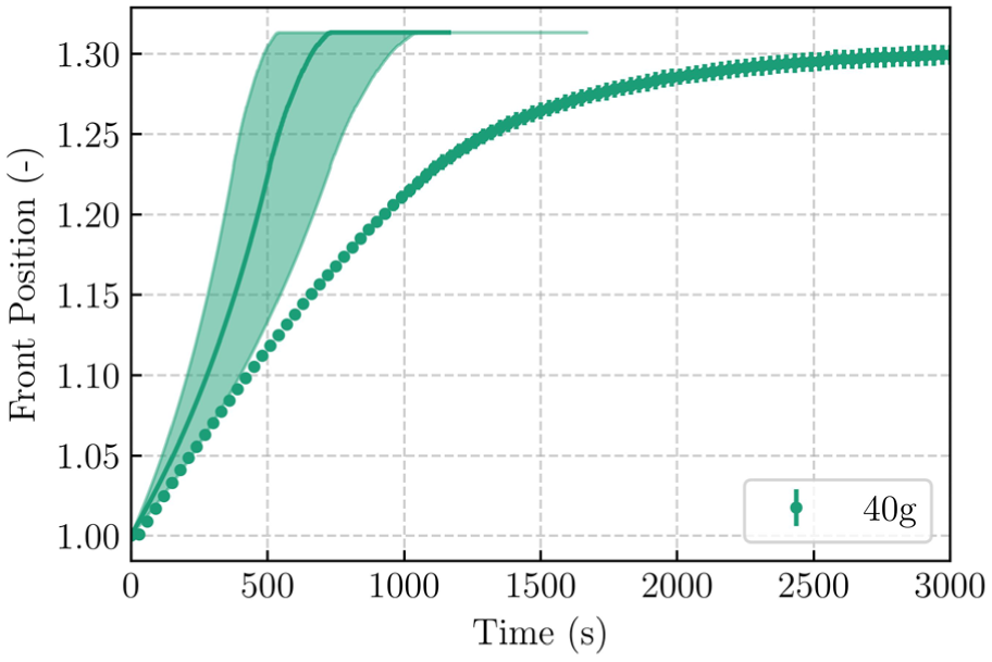
Comparison at 40g showing a slower sedimentation speed for experimental measurements compared to the model.
To reduce discrepancies between model predictions and experiments, it would be interesting to calibrate the flux function to the tested fluid, as it was done in other research (Choi et al., 2016; Lerche and Frömer, 2001; Zhang et al., 2020). Doing so, the possible effects from the polydispersity and density difference would be better captured by the fluid specific function. The shape of the curve might also differ significantly from the Richardson and Zaki flux function, pointing out that other models must be used. In fact, the Dick and Young model had a better fit for the tested fluid in (Zhang et al., 2020), while the Vesilind model was better in (Choi et al., 2016), showing that a single flux function model cannot be used for every fluid formulations. Finally, the evolution of the flux function shape variation along the increase of centrifugal acceleration should be quantified.
Over all, the model of kinematic waves is able to describe the centrifugal sedimentation of MRF over a wide range of acceleration fields ranging from 60 to 2325g. Model precision below 60g is limited by an accurate determination of the flux function across a wide range of centrifugal accelerations. It should be noted that results from this work are limited to a simplified version of MRF, without any additives rendering the viscosity even more non-newtonian. Care should therefore be taken in extrapolating results from this work to all MRF formulations, as more tests with different concentration and additives will be required to show a broader applicability of the model.
Conclusion
Centrifugal acceleration causes the separation of MRF into distinct solid and liquid phases. To characterize the motion of the particles, a simplified MRF was centrifuged in one dimensional vials. Centrifugation tests with the LUMiSizer® dispersion analyzer ranged from 40 to 2325g, measuring the progression of the sedimentation front.
The measurements are compared to a predictive model based on the kinematic waves theory. A Richardson and Zaki flux function is used to model hindered settling, adapted to MRF by taking into account the density difference between the particles and the carrier fluid. The model provides prediction with good precision above 60g, as the experimental measurements are within its predictive range. Precision increased with centrifugal acceleration, as the precision is eight times better at 500g in comparison to 60g.
Limits were however observed as the model does not agree with experimental measurement for the 40g test. The possible cause of this behavior is linked to the non-Newtonian behavior of MRF, having thixotropic properties. Accordingly, next steps should focus on the determination of the flux function, which was based on the literature for this study. It should be modified in order to better reflect the change of viscosity with centrifugal acceleration.
As the tested fluid had a simplistic formulation, futur work should address the effect of different particle concentration and fluid additives, as they modify the rheology of the fluid. These steps will be required to extend the applicability of the model from a simplistic formulation to fully formulated fluids. The impact of clutch geometry, either disk or drums, must also be studied in order to prevent centrifugation of actuators.
Footnotes
Acknowledgements
The authors would like to highlight the contribution of Infineum UK Ltd. in providing the MRF and laboratory test equipments that were used in this study.

Funding
The authors disclosed receipt of the following financial support for the research, authorship, and/or publication of this article: This research is supported by the CRIAQ (Gouvernement du Québec), NSERC (Natural Sciences and Engineering Research Council), Udes (Université de Sherbrooke), Bell Flight, Exonetik, Infineum and Gastops through a CRIAQ Exploring Innovation grant (MRFS+) and NSERC Alliance grant (ALLRP 567155-21).
Declaration of conflicting interests
The authors declared no potential conflicts of interest with respect to the research, authorship, and/or publication of this article.
Data availability statement
Data sharing not applicable to this article as no datasets were generated or analyzed during the current study.