
Abstract
A cohesive zone model is utilized to simulate grain boundary interface decohesion under load reversals with hold time being imposed at the maximum load level. This study considers the role of creep–fatigue and environment, which have been introduced as scalar damage parameters. These parameters are coupled with the traction–displacement laws governing the grain boundary cohesion and surrounding time-dependent deformation field. The accumulation of reversible fatigue damage is described using a damage rate law as a function of the elastic potential energy of the interface while creep damage is introduced using a modified Kachanov–Rabotnov type law. The role of environment is modeled by considering the grain boundary dynamic embrittlement occurring as a consequence of oxygen diffusion and accumulation in the grain boundary fracture path. The separation of damage laws into creep, fatigue, and environment, allows the examination of the influence of the different mechanisms on the intergranular crack growth rate. Theoretical aspects of the model are discussed and finite element simulations of intergranular crack growth are performed on a nickel-based superalloy, IN100, at 700℃ to illustrate the main features of the model and its comparison with the experimental data.
Introduction
Nickel-based superalloys are commonly used in many industrial components subjected to elevated temperatures and variable loading scenarios resulting in time-dependent deformation and damage processes. Many studies have investigated these materials by focusing on examining the role of creep–fatigue–environment interactions on the crack growth process (Andrieu et al., 1992; Ghonem et al., 1993a, 1993b; Krupp et al., 2004; Pfaendtner and Macmahon, 2001; Tong et al., 2001). These efforts have been described using analytical and numerical models with the goal of identifying and predicting the relative damage processes. In general, the analytical models correlate the experimental crack growth rate with global loading parameters, such as stress intensity factor and cyclic loading frequency. The limitation of these type of models is their inability to explore effects of a material’s internal variables or properties on the crack growth process. In order to incorporate failure mechanisms into a model, the cohesive zone concept has been employed. In this approach, a number of cohesive zone models (CZMs; Allen and Searcy, 2001; Helms et al., 1999; Needleman, 1990; Nguyen et al., 2001; Roe and Siegmund, 2003; Siegmund and Needleman, 1997) have been proposed to simulate the crack growth process under both monotonic or fatigue loading conditions. For example, Allen and Searcy (2001) and Helms et al. (1999) developed a micromechanical CZM in which the grain boundary (GB) is simulated as an assembly of parallel fibrils bridging the cohesive crack path interface. They applied the model to predict GB cracking in polycrystalline viscoplastic materials subjected to monotonic loading. Nguyen et al. (2001) have extended the CZM approach to cyclic loading conditions by introducing unloading–reloading hysteresis in the cohesive law. Roe and Siegmund (2003) proposed an irreversible CZM for interface fatigue crack growth simulation by coupling a continuum damage approach and a cohesive zone approach. The coupling was implemented by defining the current cohesive strength as a product of fatigue damage factor and initial cohesive strength. The fatigue damage evolution law was given in an incremental form by relating it to the current traction and separation increment rate. In a similar way, Bouvard et al. (2009) have proposed a CZM model for the prediction of creep–fatigue crack growth in single crystal superalloys. Their work considers a damage parameter which is the sum of fatigue and creep based on a strain energy release rate and Kachanov–Rabotnov type of law, respectively. The addition of environmental damage has been examined by many authors (Bika and MacMahon Jr, 1995; Carranza and Haber, 1999; Chaboche and Gallerneau, 2001). A numerical study of intergranular fracture and oxygen embrittlement in an elastic/viscoplastic solid is developed by Carranza and Haber (1999) includes coupling of the mechanical response, stress-assisted diffusion of oxygen, and a moving cohesive interface that determines crack initiation, growth, and arrest. Bika and MacMahon Jr (1995) consider environmental damage through a dynamic embrittlement process in which the stress-induced diffusion of surface atoms cause a concentration build up ahead of the crack tip resulting in decohesion.
The goal of this study is to model the intergranular dwell-fatigue crack growth in a Nickel-based superalloy by considering the fatigue, creep, and environmental damage processes associated with dwell loadings at elevated temperatures. Modeling of these events are carried out by adapting a cohesive zone approach in which the GB fracture path is viewed as an interface element with internal singular surfaces. The deformation behavior of this element is controlled by the adjacent continuum, coupled with the GB intrinsic traction–separation laws. In this, the fatigue damage due to loading and unloading is related to the separation increment rate of the interface while the creep damage evolution, due to the hold time duration, is described by a modified Kachanov–Rabotnov type law. The damage evolution due to environment is considered as a dynamic embrittlement process due to oxygen diffusion. The first part of the article presents the fatigue, creep, and environment damage evolution laws. Next, the constitutive behavior of the continuum material is presented. Dwell-fatigue crack growth experiments at 650℃ and 700℃, are described and a calibration procedure of oxygen diffusion parameters is presented based on the experimental crack growth data. Finally, finite element simulations are performed to predict intergranular crack growth rate and illustrate the role of GB creep at the crack tip.
CZM formulations
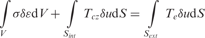
As mentioned above, cohesive zone formulations are discussed by many authors attempting to describe progression of deformation and damage events in polycrystals and single crystal materials. An examination of issues encountered in the application of these models applied to interfaces is presented in Chandra et al. (2002). In general, however, for a continuum volume including a cohesive interface, the finite element method is formulated by the principle of virtual work as
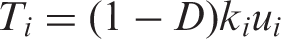
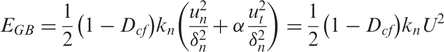
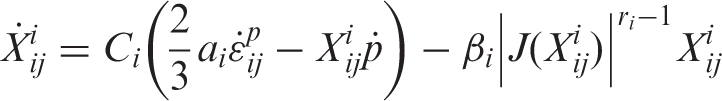
The cohesive zone law assigned for the crack tip intergranular path defines the relationship between the cohesive traction and opening displacement. A general form is written as (Alfano and Crisfield, 2001; Bouvard et al., 2009; Camanho et al., 2003; Omiya and Kishimoto, 2010)
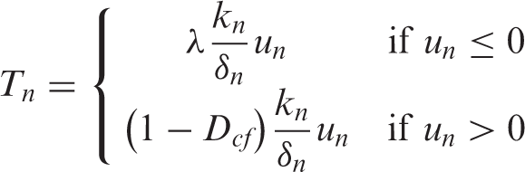
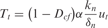

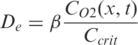
In addition, an environmental damage component, De, due to dynamic embrittlement through oxygen diffusion will be introduced. This environmental damage process is a near surface localized phenomenon, thus, De will be considered independent from Dcf. This assumption is based on the fact that the depth of oxygen penetration is very small in relation to the zone where the combined creep and fatigue damage operates. The interaction between creep, fatigue, and environment appears indirectly through the degradation of the stiffness by Dcf in the normal and tangential tractions, as expressed by equations (3) and (4), respectively. The rate of evolution for each damage parameter (Df, Dc, and De) decreases with the decrease in traction across the GB.
A failure criterion is, therefore, introduced based on the maximum value of creep–fatigue or environmental damage, which is expressed as
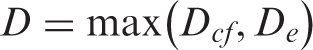
As such, crack tip advancement is assumed to occur as a result of two independent damage accumulation processes; creep plus fatigue or environment. This assumption is based on experimental observation that in IN100 at 700℃, the crack tip damage is dominated by environment (Kirchhoff, 2008). The rate of oxygen flux along the GB path is governed by the deformation field in the crack tip region which is progressively modified by the material stiffness by a function of the creep–fatigue damage accumulation. This would allow failure to occur when the parameter D reaches unity with respect to independent accumulation of creep plus fatigue or environmental damage. This general failure criterion allows the cohesive zone tractions, based on equations (3) and (4), to approach zero under conditions where the creep–fatigue damage is dominant, i.e. Dcf is accumulating faster than De does. On the contrary, if the environmental damage is dominant, the failure occurs when the cohesive zone tractions are finite. The following sections will describe the laws governing the evolution of fatigue, creep, and environmental damage components as a function of the interface traction and displacement over time.
Fatigue damage evolution law
It is understood that fatigue loading results in the accumulation of cyclic plastic strain, which is a measure of the degradation of the loaded materials. A fatigue damage law given by Lemaitre and Desmorat (2005) and Tvergaard (2005) is described by the scalar damage parameter, Df, the value of which assumes a number between 0 and 1, corresponding to no damage and complete failure, respectively. The evolution of this variable is written in terms of the cyclic plastic strain, pc, and the strain energy release rate, Y, as
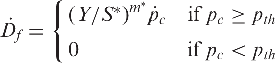
Substituting equations (3) and (4) into equation (9) yields
Creep damage evolution law
Time-dependent deformation and associated damage processes occurring in the crack tip region of superalloys are attributed to mechanisms involving GB sliding and/or cavity nucleation and growth. Observations made on post-test intergranular fracture surfaces in the alloy under study here, IN100, at the temperature levels 650℃ and 700℃, show no evidence of cavities. As such only GB sliding will be considered here. In this, GB fracture is assumed to occur when the accumulation of irreversible GB strain, over the slip length, reaches a critical limit, allowing crack tip failure to occur and the crack tip to advance over that length along an intergranular path. This slip length is described in the work of Dahal et al. (2012) as the average spacing between the slip bands intersecting GB fracture path. The GB time-dependent damage process is described by the classical Kachanov–Rabotnov creep damage law (Bouvard et al., 2009; Murakami et al., 1992) which is given as
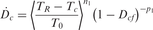
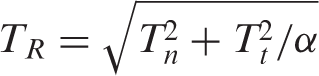
Under monotonic displacement controlled loading, as Dc, calculated from equation (11) approaches 1, the traction using equations (2) and (4) asymptotically approaches the endurance limit. To overcome this issue, a modified form of equation (11) is proposed as
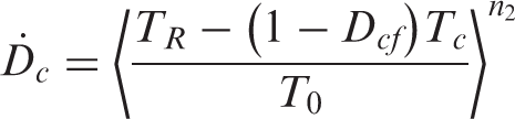
Here, Tc represents the endurance limit of the virgin material, i.e. no creep damage. This limit is diminished by the survivability factor (1 − Dcf), representing the endurance limit of a damaged material.
Environmental damage evolution law
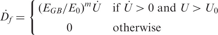
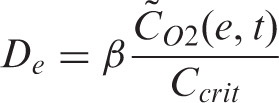
The environmental damage process in IN100 alloy is attributed to dynamic embrittlement associated with oxygen diffusion (Kirchhoff, 2008). This is supported by experimental observations that the crack growth rate in terms of length per second, da/dt, is hold time independent at a constant temperature, and the crack length, as well as, the crack opening displacement as a function of number of cycles, are continuous in nature. These observations suggest, as mentioned earlier, that the cracking process does not involve damage events that require incubation time and that environmental damage due to oxide formation can be precluded as a possible damage mechanism. This concept is discussed in the work of Maciejewski and Ghonem (2012). The dynamic embrittlement mechanism is associated with a stress-induced diffusion of oxygen atoms from the surrounding environment into the crack tip region along the affected GB path. This leads to the assumption that the environmental damage, De, is proportional to the built up oxygen concentration in the crack tip grain boundaries, given as


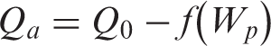
D0 is the frequency factor, Qa the stress dependent activation energy for diffusion of oxygen in the GB, R the universal gas constant, and T the absolute temperature. The work of Ghonem and Zheng (1992) has correlated Qa with inelastic strain energy density, Wp, as
The evolution law of the environmental damage as described by equation (14) is a continuous function of the position x, measured from the crack tip. In order to implement the law numerically in the finite element simulation, the average oxygen concentration in the crack tip cohesive zone element is used instead of local oxygen concentration. This can be derived by integrating over the element length, e, as
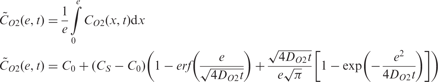
Hence, equation (14) is replaced in the simulation by
Equations (8), (13), and (20) are the requirements to satisfy the fracture criterion described in equation (6). The following section will describe the constitutive model to account for the deformation of the continuum surrounding the crack tip path.
Constitutive behavior of the continuum material
Internal state variable formulations
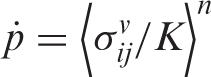
As discussed above, the cohesive interface traction–displacement laws are applied along the GB crack path. The deformation of this path is governed by the viscoplastic response of the surrounding continuum, the constitutive equations of which are modeled on the basis of a nonlinear kinematic hardening material. The model is formulated on the assumption that a viscoplastic potential, Ω, exists in the stress space and is a function of the viscous stress,
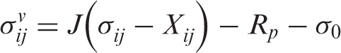
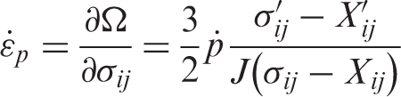
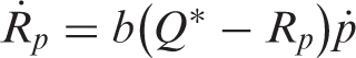
The hardening rules can be divided into two categories, kinematic and isotropic hardenings. The kinematic hardening terms can be described by the motion of the center of the yield surface, which is measured by the back stress,
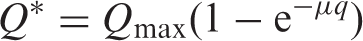
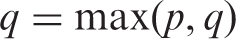
The slow evolution of microstructure associated with cyclic hardening or softening of the material can be described by the isotropic hardening variable, Rp, and is governed by the following equations (Nouailhas, 1987, 1989; Zaki and Ghonem, 2000)
Simulation and validation of the internal state variable model
The material employed in this study is Inconel 100 (IN100), a P/M processed nickel-based superalloy having the composition (in wt%): Al 4.85, Ti 4.24, Co 18.23, Cr 12.13, Mo 3.22, V 0.71, Zr 0.071, B 0.02, C 0.072 (Wusatowska-Sarnek et al., 2003). The heat treatment of the as received material is a three stage process (Kirchhoff, 2008). The average Rockwell C hardness of the as received material is 42.7 HRC and its microstructure, which is shown in Figure 1, includes primary γ′ located at the triple points of the grain boundaries as well as secondary and tertiary γ′ within the grains and carbides mostly located along the grain boundaries. The average grain size is 5 µm (ASTM 12).
(a) Secondary electron image of the as received IN100 microstructure, etched with 0.6 g granulated Na2O2 and 50 mL HCl applied for 7–10 min, showing secondary and tertiary γ′ in the matrix, primary γ′ and carbides located along the grain boundaries and (b) transmission electron micrograph of the as received IN100 showing details of the tertiary γ′.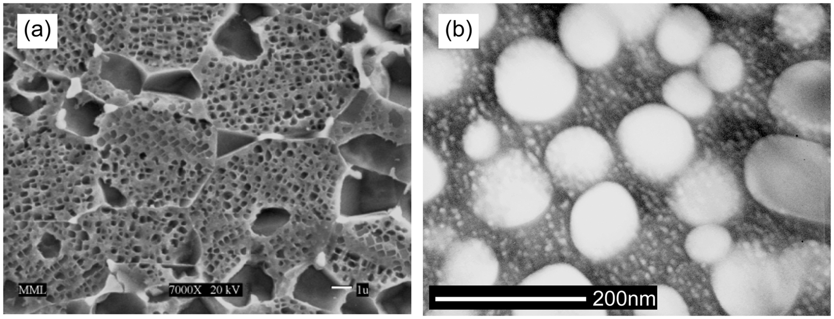
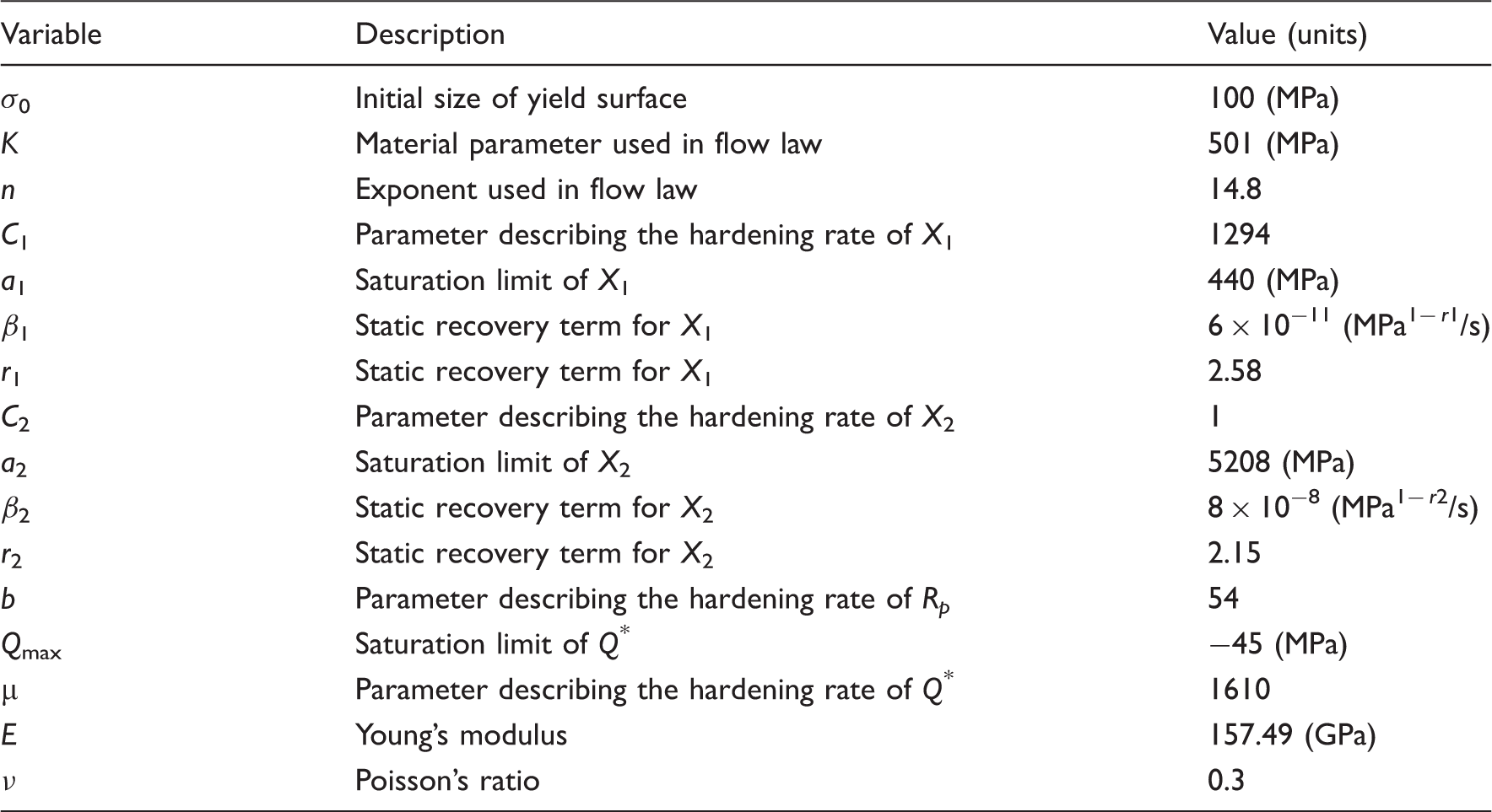
The constitutive formulations described by equations (21) to (27) are implemented into a UMAT subroutine. The material parameters required to implement the set of equations listed in the previous section are determined from results of low cycle fatigue (LCF) tests carried out at 700℃ in a procedure detailed in the work of Maciejewski et al. (2012). These parameters, presented in Table 1, are invoked in a subroutine within an ABAQUS platform to solve the above mentioned equations and simulate uniaxial monotonic and cyclic strain controlled conditions. The stress versus strain results of this simulation are compared with those obtained experimentally, as shown in Figure 2. The comparison in Figure 2 shows the numerical and experimental results are in good agreement thus validates the implementation of our UMAT code and confirms the material constants used in this study.
Experimental and numerical stress versus strain curves at 700℃ under strain controlled loading: (a) monotonic loading at two strain rates, 1 × 10⁻⁵ s−1 and 5 × 10⁻⁵ s−1 and (b) cyclic loading at a strain rate of 5 × 10⁻⁵ s−1 for two strain ranges, Internal state variable model material constants for IN100 at 700℃.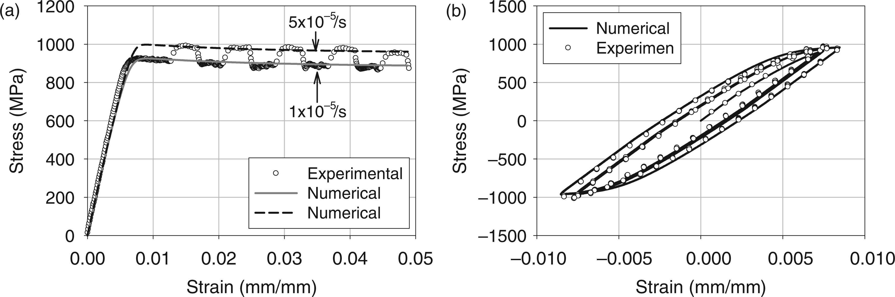
Parameter identification for the environment damage evolution law
Determination of the oxygen diffusion coefficient, DO2, is required to calculate the concentration of oxygen accumulated in the crack tip region. Calculation of this coefficient requires the knowledge of the related activation energy, Qa, and the frequency factor, D0. Calibration of these two parameters is done using crack growth data in the manner described below.
A series of dwell crack growth tests are carried out using compact tension (CT) specimens made of IN100 at two temperatures, 650℃ and 700℃, in air environment. The cyclic loading profile in these tests consists of 1 s loading, 1 s unloading, and a dwell time of 100, 600 and 7200 s at the maximum load level. All tests were performed at a stress ratio of 0.1 with crack propagation being monitored using the potential drop technique. Details of these tests are given in Kirchhoff (2008) and Maciejewski and Ghonem (2012). The typical intergranular crack path and fracture surface appearance are shown in Figure 3. In this figure, the presence of secondary cracking indicates that the creep component is an active damage parameter and damage is not a localized process, i.e. not fully controlled by environment, thus justifying the independency between the creep–fatigue and environment processes.
Typical intergranular (a) crack path and (b) fracture surface in alloy IN100 during hold time crack growth testing at elevated temperatures.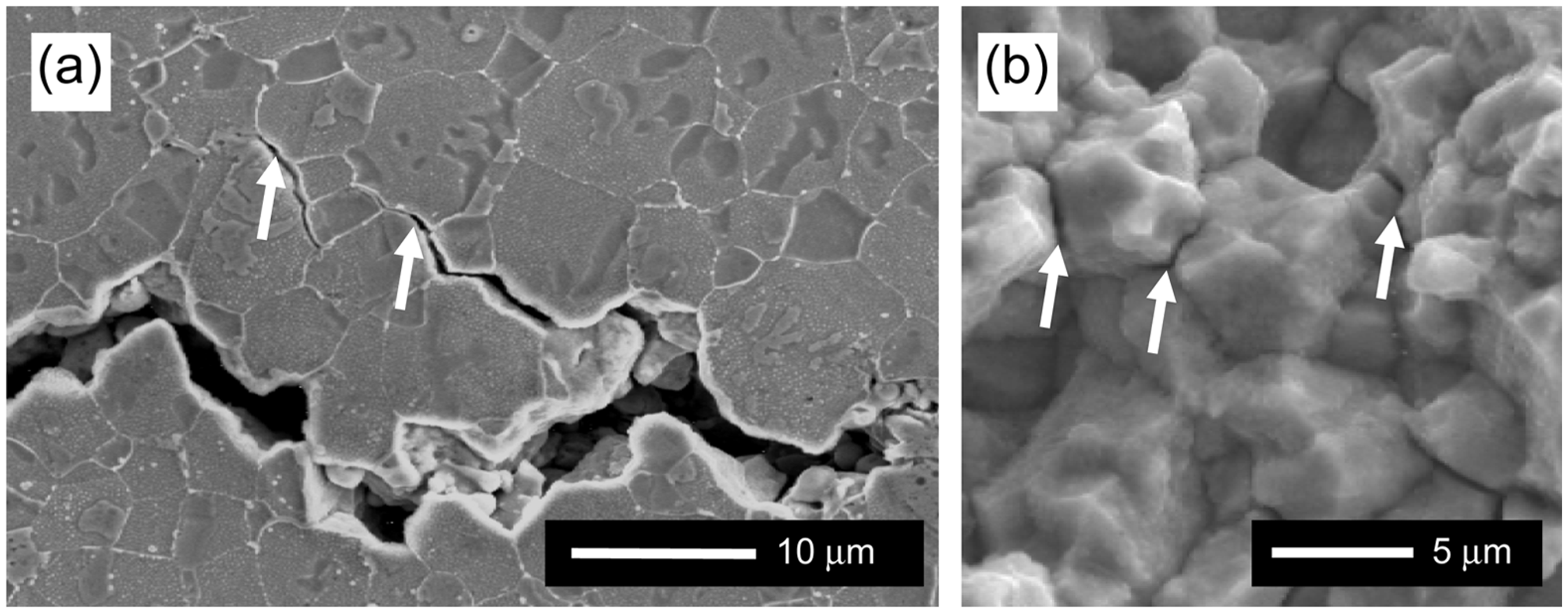
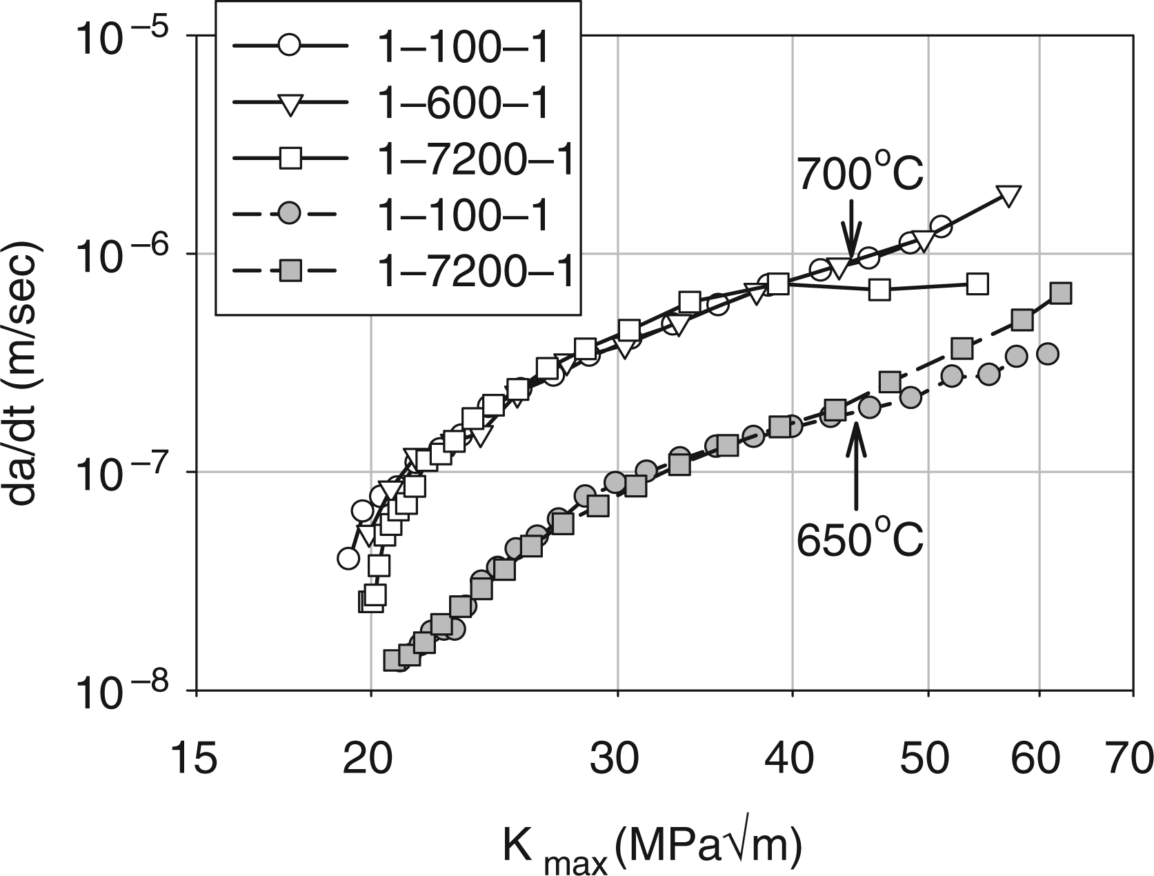
The crack growth rate in terms of da/dt versus Kmax, is shown in Figure 4. This figure indicates that da/dt is independent of hold time and is only a function of the test temperature. As such, da/dt being a thermally activated parameter, it can be fit into an Arrhenius type law in the form
Crack growth rate, in terms of da/dt versus Kmax, as a function of temperature and hold time duration for IN100 in air environment. (a) Crack growth rate, da/dt, versus the inverse of absolute temperature for different Kmax values and (b) apparent activation energy as a function of Kmax for IN100 in an air environment.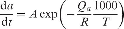

To calculate the frequency factor, D0, De is set to 1, thus, rearranging equation (19) yields an average concentration of oxygen in an element,
Intergranular crack growth simulation
Finite element simulation
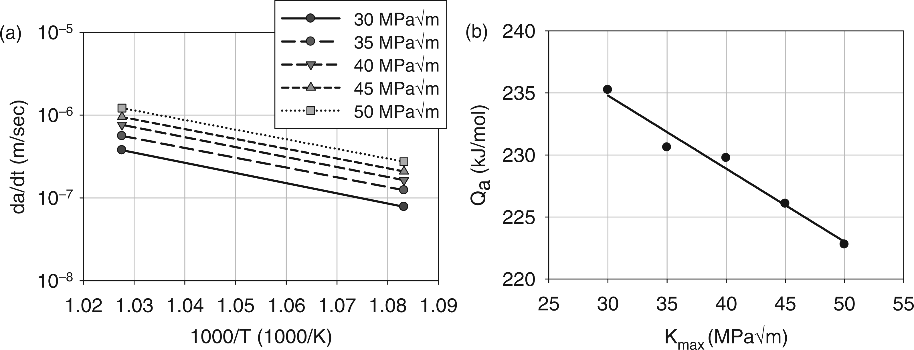
Creep–fatigue crack growth tests of a CT specimen under mode I, load controlled conditions, were simulated with a two-dimensional finite element procedure using ABAQUS platform. The CT specimen meshing and geometry are shown in Figure 6 with an initial crack length of 7.62 mm, a width of 25.4 mm, and a thickness of 6.35 mm. In order to predict the numerical crack growth rate, four initial crack lengths were used to simulate various Kmax conditions. These lengths were 7.62, 10.81, 11.83, and 13.66 mm. The meshing consists of three node linear and four node bilinear elements under the plain strain with an element size of 1 µm at the crack tip. The loading profile consists of a ramp up in 1 s to a maximum load of 5 kN, dwell at maximum load for 100 s, and ramp down in 1 s to a minimum load of 0.5 kN. The crack propagation is assumed to occur along a predefined intergranular path corresponding to the symmetry line of the specimen, which is modeled as a cohesive interface. The properties used to define the behavior of the cohesive zone are shown in Table 2, while the material constants used for the continuum material are the same as those listed in Table 1. Again, it should be mentioned that a focus is made at a temperature of 700℃ for this study.
Finite element model geometry and meshing of a CT specimen with an initial crack length of 7.62 mm. Cohesive zone interface model material constants for IN100 at 700℃. GB: grain boundary.
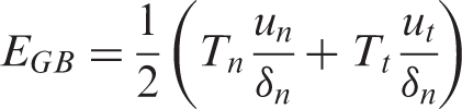
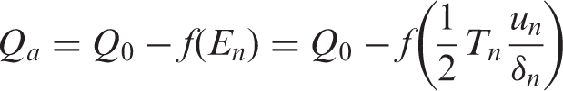
In order to perform a finite element simulation of the crack growth process using a CZM, it is necessary to relate the crack tip element activation energy with the outputs of the CZM, i.e. opening displacements and tractions. Considering that the Kmax characterizes the stress field in crack tip region in elastic fracture mechanics, an attempt to relate Kmax with the cohesive zone variables at the crack tip is carried out. The crack tip tractions and opening displacements were obtained through finite element analysis by carrying out monotonic loading simulations at three load levels, 3, 4, and 5 kN with Dcf = 0 at a loading rate of 5 kN/s. The normal potential energy, En, of the cohesive zone at the crack tip node was calculated at peak load for each condition and plotted as a function of the corresponding Kmax, as shown in Figure 7. This curve is fit to the following polynomial form
Relationship between crack tip potential energy, En, and maximum stress intensity factor, Kmax.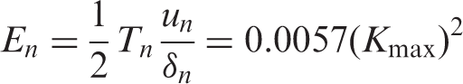
Substituting equation (30) into (29) yields a new expression for equation (18)
This expression of Qa will be substituted in equation (16) in order to calculate the parameter DO2 .
Prediction of intergranular crack growth rate
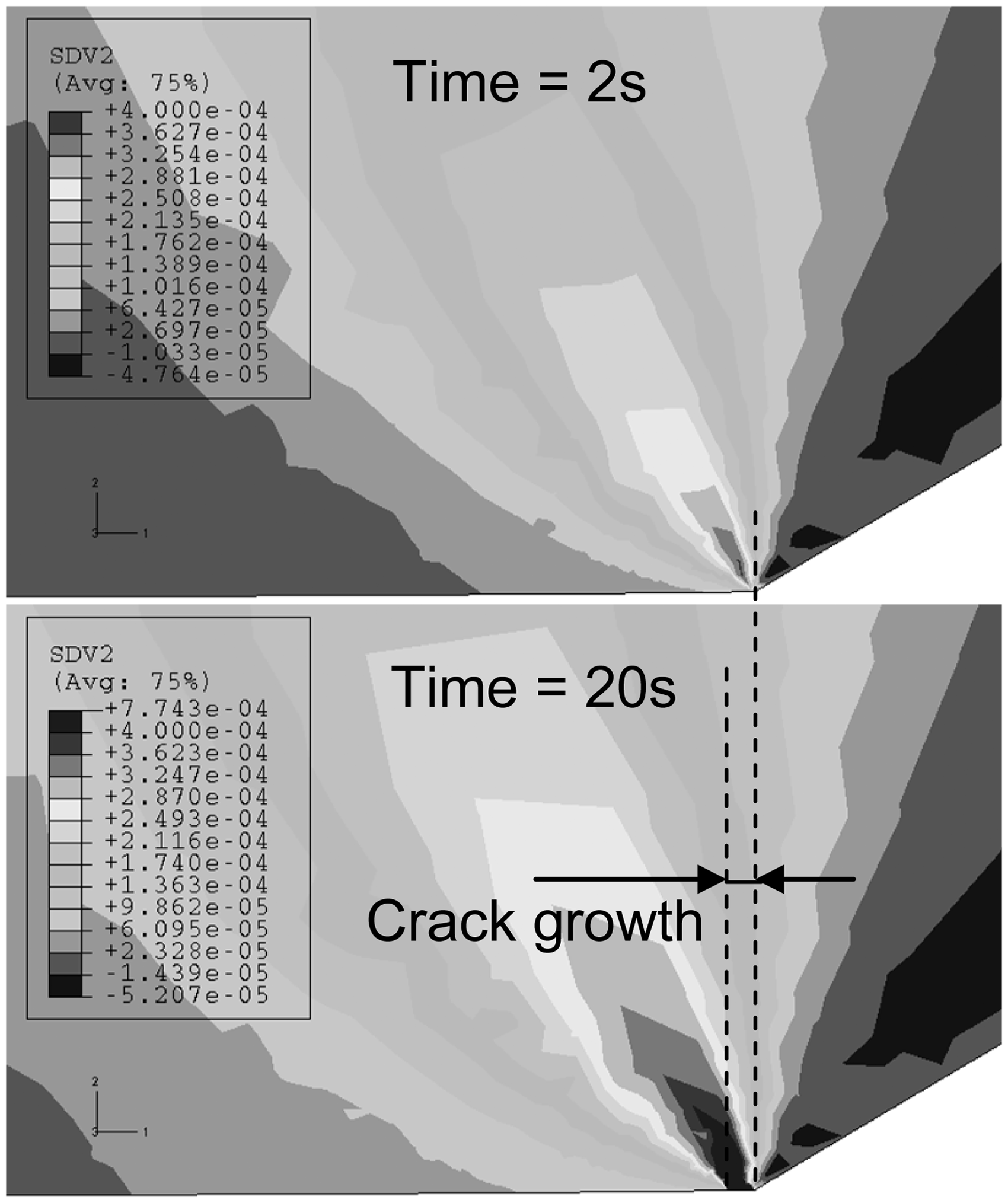
Two intergranular crack growth simulation cases were performed. The first case considers that both creep and fatigue damage are progressing at a rate much smaller than the environmental damage, thus, Dcf is not considered. The second case considers that role of Dcf. Both cases, however, consider that environmental damage is present and thus the time evolution of De is included. The important aspect in the second case simulation is that the presence of fatigue and creep damage of the cohesive zone acts as a softening mechanism along grain boundaries in the crack tip region. This stress relaxation can affect the amount of oxygen diffusion and consequently the crack growth rate. These two cases were simulated for different Kmax value as discussed in ‘Finite element simulation’ and the resulting crack growth rates are shown in Figure 8 with the corresponding experimental curve. This figure illustrates that both case studies are in good agreement with the experimental results. In general, the case study which considers Dcf exists has a lower crack growth rate then the case study which considers Dcf = 0. The inclusion of fatigue–creep damage retards the crack growth through the decrease of the cohesive zone traction at the crack tip region. Figure 9 is a typical example of a CT specimen with a viscoplastic continuum and GB interface including Dcf, showing the amount of relaxation, characterized by the accumulated inelastic strain, in the crack tip region increases as a function of time. A lower traction corresponds to higher activation energy for diffusion of oxygen, leading to a decrease in diffusivity of oxygen in the GB and a decrease in concentration of oxygen. Thus, during environmental controlled damage, the crack growth rate is lower for a material with a higher relaxation in Tn. This relaxation in crack tip traction is controlled by the surrounding continuum in the case where Dcf = 0 and both the continuum and interface in the case which considers Dcf exists.
Comparison of simulated and experimental crack growth rates at a loading frequency of 1 s–100 s–1 s at 700℃. Accumulated inelastic strain in vertical direction during GB cracking as a function of time.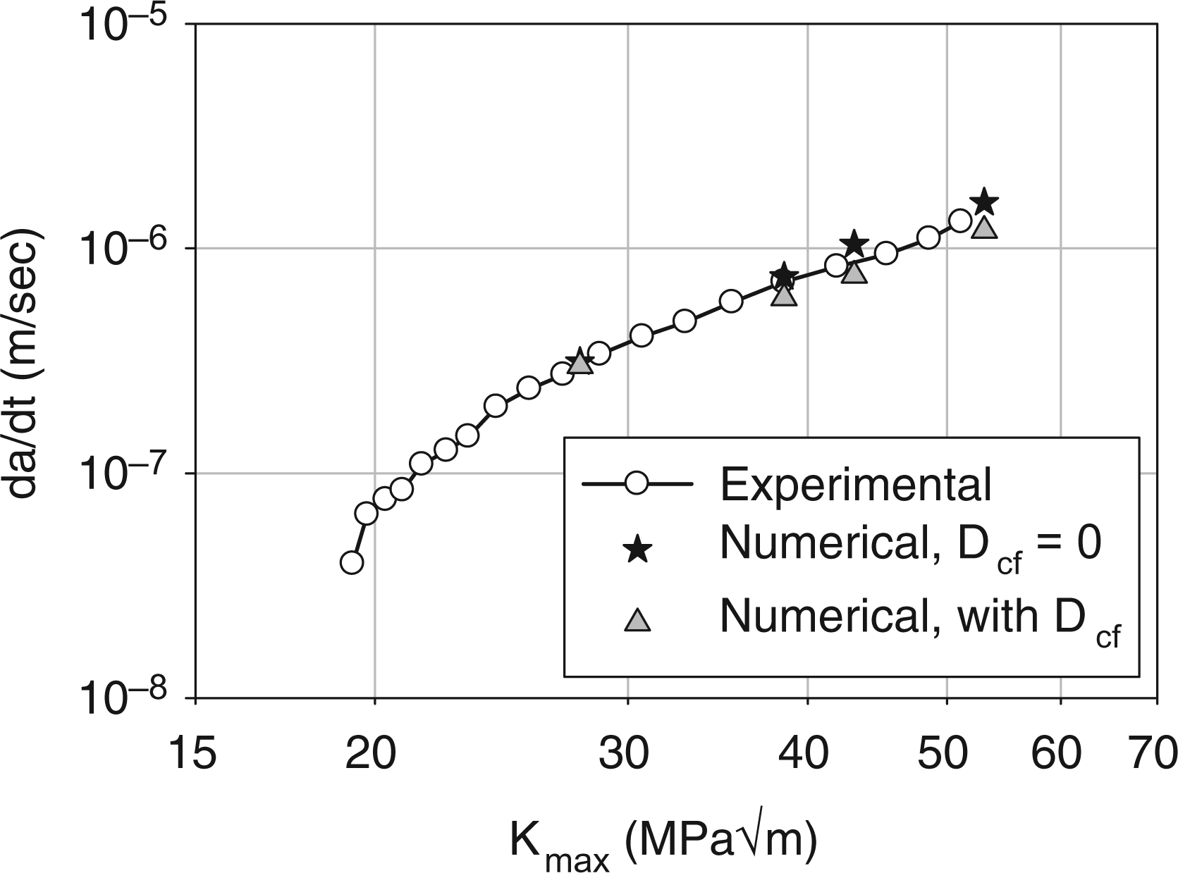
Many studies have shown that the partial pressure of oxygen has an effect on the crack growth rate. This section will simulate the partial pressure of oxygen by varying the surface concentration of oxygen, Cs. The predicted crack growth rates are shown in Figure 10 with the experimental condition corresponding to an air environment (Cs = 21%). This figure shows that an increase in Cs results in an increase in da/dt. The difference between the surface concentration of oxygen and the concentration of oxygen in the bulk material, Cs − C0, controls the oxygen flux and its reduction decreases the diffusion of oxygen in the GB. The concentration of oxygen in the GB controls the amount of environmental damage, De, thus affecting the da/dt. The da/dt decrease more for a decrease of Cs from 19% to 17% than for that from 21% to 19% because the oxygen diffusion rate becomes lower for a smaller oxygen concentration gradient. In addition, the da/dt for the different Cs values are almost parallel, implying that the environmental damage evolution plays a dominant role in the intergranular crack growth process.
Comparison of simulated and experimental crack growth rates at a loading frequency of 1 s–100 s–1 s at 700℃ considering Dcf and De. The simulations were carried out with varying values of Cs.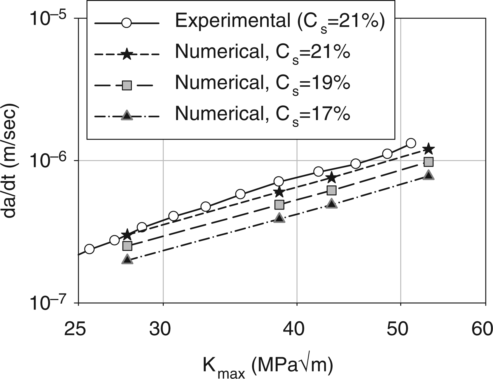
Conclusions
In this study, an intergranular crack growth model based on damage mechanics that account for the role of creep–fatigue and environment has been developed for the nickel-based alloy, IN100. The model is phenomenological in nature and utilizes scalar damage parameters which characterize the decohesion events taking place along the GB fracture path subjected to dwell fatigue loading. Outcomes of these events are the result of complex interactions of fatigue, creep, and environment related damage mechanisms. The accumulation of fatigue damage is described using a damage rate law as a function of the elastic potential energy of the GB interface while creep damage is introduced using a Kachanov–Rabotnov type law. The environmental damage is described in terms of GB dynamic embrittlement associated with oxygen diffusion and accumulation in the GB fracture path. The separation of damage laws into creep, fatigue, and environment is intended to provide the ability to assess the relative influence of the different damage components on the intergranular crack growth rate. These scalar damage parameters are introduced into a CZM, the main features of which are as follows:
The GB crack path is viewed as a cohesive interface, the deformation and damage of which are represented by traction–displacement laws. The deformation boundary conditions of this interface are governed by the viscoplastic response of the surrounding continuum which is modeled on the basis of a nonlinear kinematic hardening material. An experimental program has been carried out in order to define the material parameters for both the continuum and the GB interface. A series of LCF tests were carried out at 700℃ under different strain controlled loading scenarios. Analyses of these tests provide means of determining the material parameters necessary to implement the internal state variable model describing the continuum deformation behavior. In addition, uniaxial test cases compared well with those obtained experimentally. Dwell time crack growth tests were carried out on CT specimens at two temperatures, 650℃ and 700℃, in air environment to provide knowledge related to intergranular cracking mechanisms. Results of these tests show that the crack growth rate, while temperature dependent, is independent of the hold time duration. The crack tip apparent activation energy, Qa, is calculated from knowledge of da/dt as a function of temperature and is correlated independently with Kmax and the crack tip normal elastic potential energy, En, for use in the GB interface laws. A fracture criterion considering failure by either creep–fatigue or environment has been implemented. The interaction between creep–fatigue and environment is implicit to the model through the relaxation of the stress field at the crack tip. A comparative study of crack growth simulations were carried out by including or excluding the creep–fatigue damage component in the CZM on IN100 with a focus on 700℃. Results of this study show the following:
Simulated da/dt is found to be in good agreement with that obtained experimentally at 700℃, thus indicating the validity of the damage parameter formulations. The environmental effect plays a more important role than the creep damage in the dwell fatigue crack growth of IN100 in air at 700℃. The high crack tip stresses assist the oxygen diffusion into the crack tip along grain boundaries and contribute to the environmental damage. The resistance of this environmental damage could be done by fast relaxation of crack tip stresses resulting in a slower diffusion of oxygen along grain boundaries. This relaxation results from both the continuum stress field and the decrease in cohesive stiffness caused the by the creep–fatigue damage component in the GB interface.
Footnotes
Funding
This research received no specific grant from any funding agency in the public, commercial, or not-for-profit sectors.