






Abstract
This study systematically investigated the influence of slot angle on the directional fracture capability and slotting effect of slotted cartridges. Initially, Two-dimensional dynamic caustic experiments were utilized to assess the dynamic behavior of blast-induced cracks under various a configurations. 3D PMMA column model experiments and CT scans were conducted to characterize blasting-induced cracks and assess the directional fracture capability of slotted cartridges. The laboratory findings were validated through field tests. The results indicated that different a could consistently produce directional cracks, and the longest secondary crack was longer when a was below 180°. The magnitude of superimposed stress waves generated during the propagation of the two primary cracks determined the length of the longest secondary crack, while the size of stress waves altered the angle between the longest secondary crack and the primary cracks. The a is inversely proportional to the damage in the non-slot regions. The 3D PMMA column model experiments further validated the findings from the 2D dynamic caustic experiments. An increased a resulted in gradual decreases in the fractal dimension, damage value, and surface area of cracks. Field tests demonstrated that selecting slot angles that match the profile can effectively control over-excavation and under-excavation, thereby substantially improving blast hole utilization efficiency.
Introduction
With continuously rising demands for precision in engineering blasting, the directional fracture control technology using slotted cartridges has been extensively applied in various projects because it facilitates crack propagation along the slot direction to create a smooth profile surface (Minh et al., 2021).
The slotted cartridge (see Figure 1(a)) is a blasting device wrapped in a shell designed with pre-defined slots. It guides the directed release of explosive energy through these slots to enable precise control over the blasting direction and range while minimizing disturbance to non-blasted regions. Fourney et al. (1978, 1983) were the pioneers in using slotted pipes for directional fracture control in blasting operations and demonstrated their capabilities to induce cracks along specified directions. Thereafter, researchers have utilized various methods, including high-speed schlieren photographic systems (Yang and Zuo, 2019), dynamic caustic experiments (Ding et al., 2024b; Yang et al., 2020), numerical simulations (Shu et al., 2019), and field tests (Xiao et al., 2024a), to further confirm the effectiveness of slotted cartridges in inducing directional fractures and to explore the topic in greater depth. The parameters of the slotted pipes used in slotted cartridges are crucial factors influencing the propagation of directional cracks. Consequently, numerous researchers have conducted detailed studies on slotted pipe parameters, such as slotted width (Li et al., 2024), slotted pipe thickness (Wang et al., 2024), slotted pipe material (Yang et al., 2019), number of slots (Ding et al., 2022; You et al., 2024), and charge structures (e.g., decoupling coefficients Li et al., 2023, Yang et al., 2023a, slot shapes Tian et al., 2023, coupling media Yang et al., 2019b; Xie and Wu, 2016, and charge amounts Yang et al., 2018). Li et al. (2024) found that there is an inverse tangent relationship between the slot width and the angle between the primary cracks based on dynamic caustic experiments. Wang et al. (2024) investigated the impact of slotted pipe wall thickness on explosive dynamic behavior through experiments and numerical simulations. Yang et al. (2019) explored how the slotted pipe material influences the propagation of shock waves and explosive gases. Kang et al. (2022) revealed the formation mechanisms and propagation characteristics of blasting-induced cracks in slotted cartridges with different numbers of slots based on PMMA material. Additionally, scholars have conducted studies on charge structures. For example, Wang (2017) investigated how decoupling coefficients affect the dynamic fracturing of blasting-induced cracks and their relationship to blasting damage. Wang et al. (2021) conducted numerical simulations to examine the blasting effects and the associated damage to rock masses resulting from eccentric decoupled charges of slotted cartridges. Yang et al. (2012) optimized the structural parameters of slotted cartridges via orthogonal experiments and applied the findings in engineering practice.
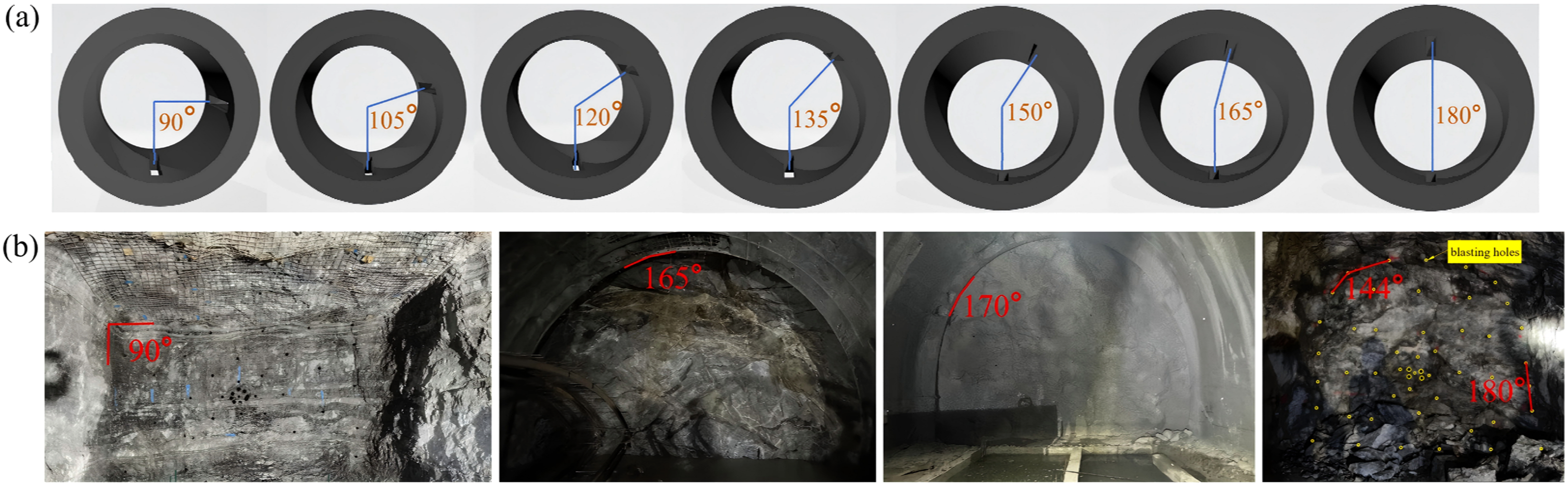
(a) Schematic diagram of the slotted pipe; and (b) profile of the blasting zone (Examples of required slot angles for different positions).
Researchers have examined slotted cartridges in practical engineering applications. For instance, Yang et al. (2019a), along with other scholars (Zhang et al., 2022), analyzed the impact of ground stress on the propagation of blasting-induced cracks from slotted cartridges. Yue et al. (2018a) explored the influence of blast hole spacing on the propagation of cracks between holes. Many scholars (Ding et al., 2024a; Yue et al., 2025) have studied the blasting effect of a slotted cartridge in layered rock mass. Wang et al. (2025a) studied the dynamic fracture mechanics behavior of layered rock mass with two beddings under an explosive load of slotted charges. Cai et al. (2024) studied the interaction between joint and slot blasting through model experiments and numerical simulation. Yue et al. (2018b) revealed the dynamic mechanical behavior of cracks between blast holes during slotted cartridge micro-differential blasting. Ding et al. (2021) explored the interaction between directional cracks generated by slotted cartridges and opened joints. Cheng et al. (2023) suggested a lateral circumferential slot charge to improve rock-breaking capability on the inner side of the cavity. Huang et al. (2023) examined the effectiveness of circumferential slotted cartridges in improving blasting fragmentation.
Existing research has mainly focused on symmetric slot configuration of slotted cartridges (i.e., a = 180°). However, no systematic research has been conducted on the directional fracture mechanisms of slotted cartridges with asymmetric slot angles. Ding et al. (2024) investigated the damage control performance of blasting with slotted cartridges at a = 90°. Nevertheless, blasting profiles in mining, tunnel excavation, and other similar engineering projects exhibit asymmetric characteristics, as shown in Figure 1(b). Adjusting the slot angle is essential to achieve directional fractures and control over-excavation. This engineering demand highlights the existing research gap. Therefore, it is urgent to clarify the influence of slot angle on directional fracture capability. Systematic studies on the slot angle, a critical parameter influencing directional fractures, have not yet been undertaken. There is an urgent need to address the varying requirements for slot angles across different engineering profiles. Therefore, this study investigated the directional fracture capacity related to slot angles. First, a theoretical formula for calculating the hole wall pressure of slotted cartridges was derived based on detonation wave theory, variations in stress intensity factors at different slot angles, and stress decay patterns. 2D dynamic caustic experiments were conducted to assess the effects of different slot angles on directional fracture capability. Fractal theory was utilized to quantitatively analyze the impact of varying slot angles on the damage associated with blasting-induced crack propagation. 3D blasting experiments were conducted using PMMA columns, and CT scanning was employed to determine the directional fracture capability of blasting-induced cracks. Finally, field application tests demonstrated that choosing slotted cartridges with slot angles suitable for the profiles can significantly minimize over-excavation.
Blasting hole wall pressure of slotted cartridge
Theoretical calculation
Hole wall pressure directly reflects the impact of explosive energy on the rock mass. Its magnitude and distribution determine the rock mass's ability to fracture along the slot direction, the controllability of fracture extent, and the risk of damage to the surrounding retained rock mass. Calculating hole wall pressure allows for the optimization of parameters such as slot angle and charge amount to achieve the desired blasting effect while minimizing unnecessary disturbances to rock masses in non-blasted regions. This provides a quantitative basis for evaluating blasting effectiveness while ensuring project stability and safety.
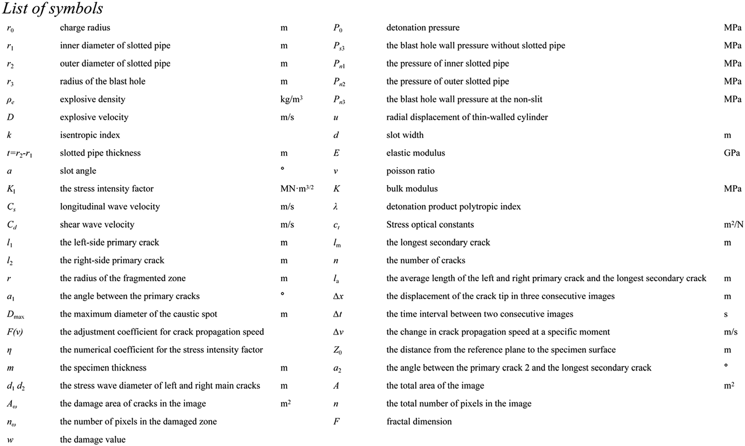
All parameters are shown in the list of symbols.
The detonation pressure of the explosive is defined by the Chapman-Jouguet (C-J) theory:

The absence of slotted pipe material at the slot location allows the explosive gases to act directly on the blast hole wall through the gap. The pressure from the explosive surface (r0) to the hole wall (r3) decays following the isentropic expansion of the detonation products (Li et al., 2026), where the gap is assumed to be filled with detonation products.

At the non-slot locations, the pressure from the explosive surface (r0) to the inner wall of the circular pipe (r1) is calculated using Eq. (2):

The Pn1 at the non-slot directly acts on the inner wall r1 of the slotted pipe, resulting in stress in the slotted pipe, which is then transmitted to the outer wall r2. According to the basic assumptions of the thin-walled cylinder, when (r2-r1)/r1 ≤ 0.1, the expression of the radial displacement u of the thin-walled cylinder is:

This displacement will cause the outer wall of the slotted tube to expand outward, thereby compressing the medium in the blasthole, resulting in pressure Pn2. Assuming that the elastic response of the surrounding medium can be expressed by the bulk modulus K, then the pressure Pn2 is related to the volume strain ΔV/V.



Combining Eqs. (1), (4)-(7), we obtain:

The detonation pressure will gradually decay after passing through the slotted pipe. According to formula 2, the pressure Pn2 of the hole wall at the slot at the hole wall r3 is:

Numerical simulation verification
Using Ansys/Ls-dyna modeling, in order to reduce the amount of calculation, a quasi-two-dimensional model is established. The length of the model is 2 m, the width is 2 m, the thickness is 1 cm, the middle of the model is the blast hole, and the charge radius (r0) is 0.16 m. The inner (r1) and outer (r2) diameters of the slotted pipe are 0.18 m and 0.20 m, respectively. The blast hole radius (r3) is 0.25 m, the slot width is 0.2 cm, and slotted pipes with different angles were established, respectively (Wang et al., 2025b; Zhang and Mang, 2020; Zhang and Wang, 2018). The whole model is shown in the following Figure 2. The rock is modeled using the RHT model, and the specific parameters refer to the marble parameters from Li (Li et al., 2017).
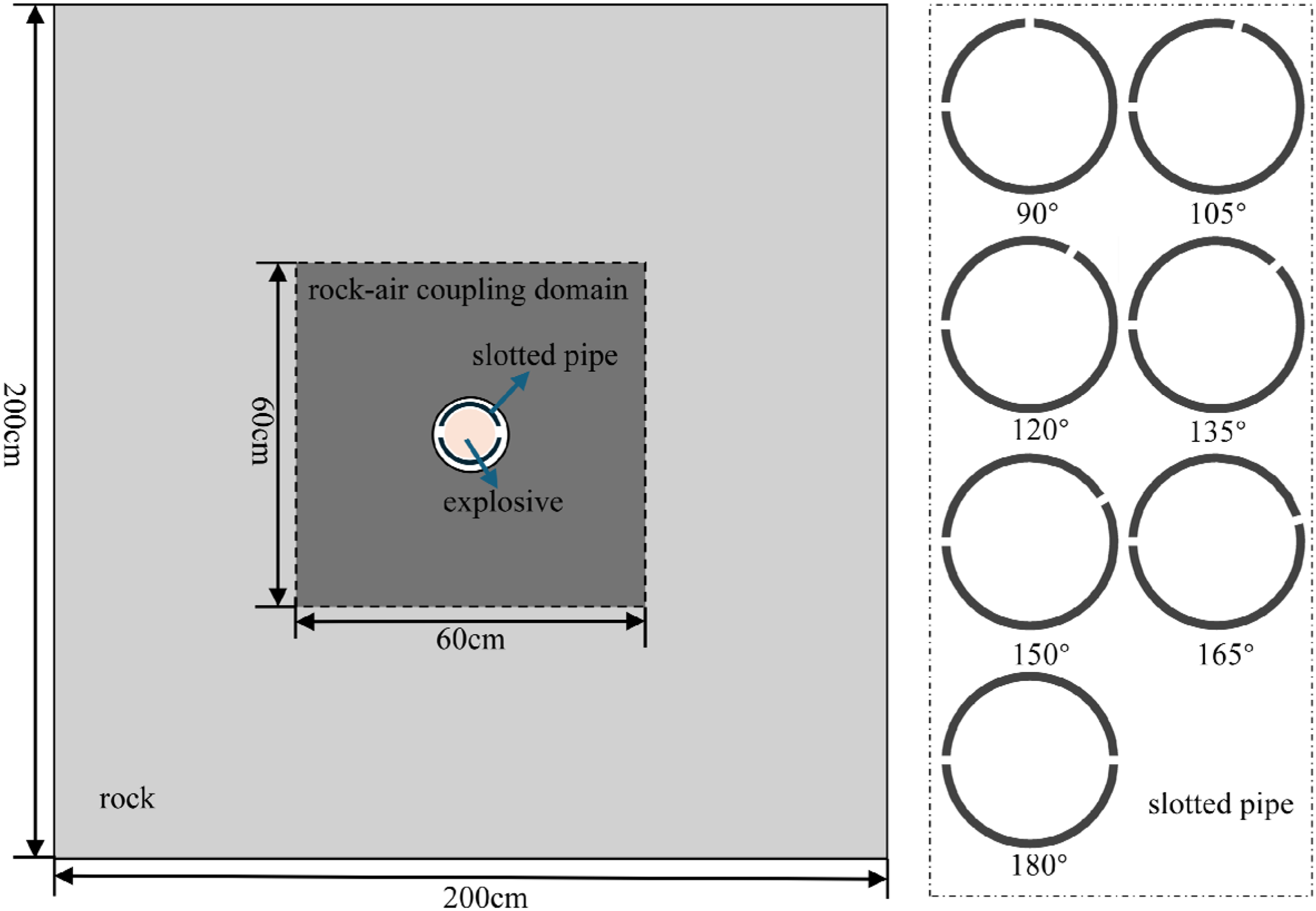
Numerical simulation model diagram.
As shown in Figure 3(a), after the blasting of the 90° slotted cartridge, the hole wall elements at the two slits are taken to analyze the hole wall pressure. It can be seen that the time history curve of the hole wall pressure at the slot is basically coincident. At the same time, the other elements are taken to calculate the average hole wall pressure value, which is regarded as the hole wall pressure at the non-slot. The average hole wall pressure at the slot and the average hole wall pressure at the non-slot under different slot angles are extracted as shown in Figure 3(b). The average hole wall pressure at the slot at different angles is 1352.40 MPa, and the average hole wall pressure at the non-slot at different angles is 929.68 MPa. The theoretical calculation values are 1452.34 MPa and 954.39 MPa, respectively, and the error is less than 7%.
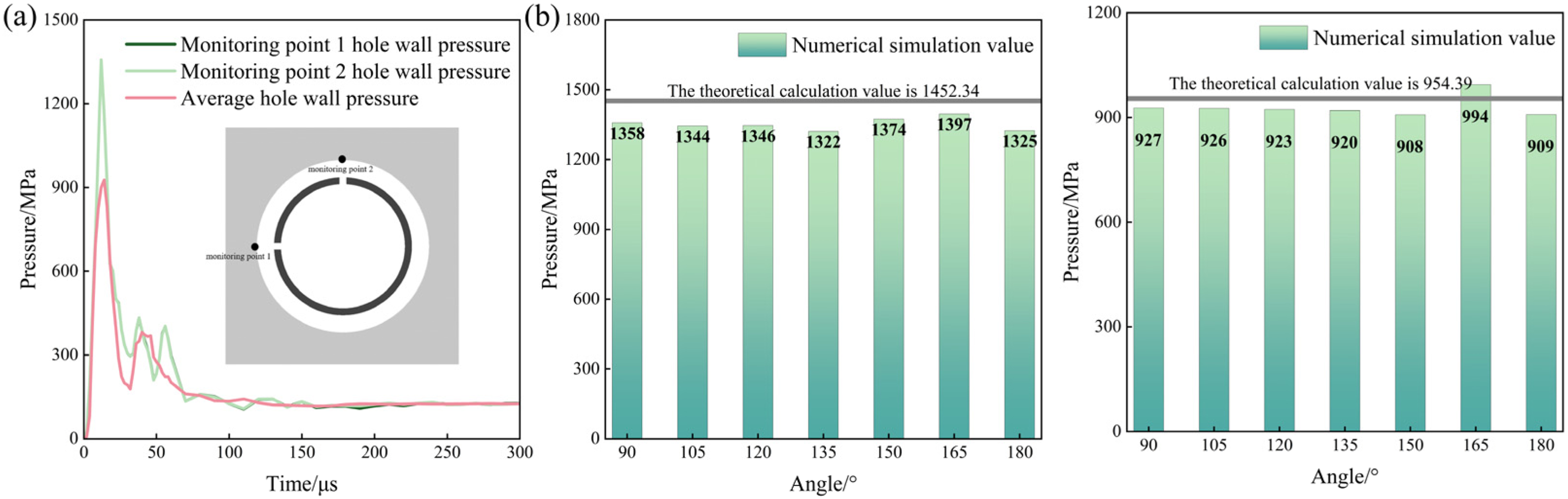
(a) Pressure time history curves of hole wall at different positions; and (b) comparison of theoretical calculation and simulation results.
Dynamic caustic experimental system and analysis
Experimental system
In the nineteenth century, Airy identified the phenomenon of caustics, and in the 1950s, Manoggie proposed the caustic method to address singular field problems. When solids are subjected to stress, their optical properties vary according to their mechanical state: tensile stress reduces material thickness and lowers the refractive index. The caustic method utilizes these optical and mechanical properties to characterize the variations in the stress fields at crack tips by measuring the size of caustic spots. This experiment employed a reflective digital laser dynamic caustic system. It consists of a laser, a beam expander, a field lens, a high-speed camera (exposure time is 7.68 μs, that is, the frame interval is 7.68 μs, and the resolution is 128 × 128), a synchronization switch, and a computer, as illustrated in Figure 4(a). The laser emits light waves, which are converted into parallel light by the beam expander and field lens 1 before they reach the specimen's surface. After the specimen deforms under explosive loading, the refracted light from its surface forms caustic lines (bright curves) and caustic spots (shadow zones) at a reference plane located at a distance Z0 from the undeformed surface. The refracted light is converged by field lens 2 and directed to the high-speed camera, which captures dynamic caustic images throughout the explosion process. The light path is illustrated in Figure 4(b).
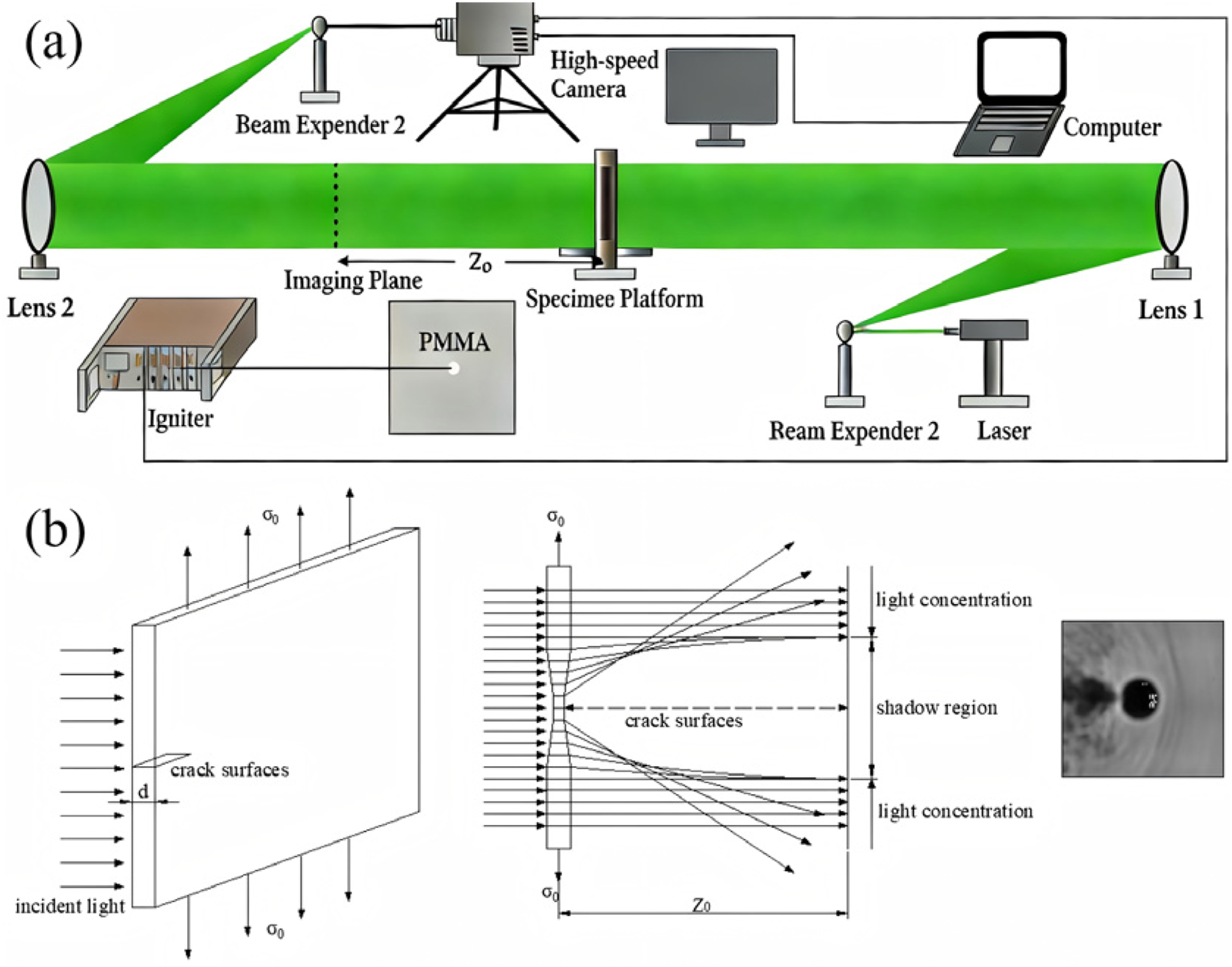
(a) Reflective digital laser dynamic caustic line experimental system; and (b) schematic diagram of caustics.
Experimental model and parameters
Research by Kutter H.K. et al. (Rossmanith et al., 1997) indicated that the crack propagation mechanism of polymethyl methacrylate (PMMA) under explosive loads resembles that of rock. Additionally, PMMA features good optical clarity and mechanical isotropy, which makes it appropriate for dynamic caustic experiments. Its dynamic mechanical parameters (Yue et al., 2025) are listed in Table 1.
Dynamic mechanical parameters of PMMA.

The specimen is a 250 mm × 250 mm × 5 mm PMMA plate with a centrally pre-fabricated blast hole of 10 mm in diameter. The slotted pipe illustrated in Figure 1(a) was produced using the 3D printing technology with Future 8200Pro resin. The specific parameters are shown in Table 2. It features a slot width of 0.5 mm, a thickness of 1 mm, an inner diameter of 6 mm, and an outer diameter of 8 mm. The explosive used is lead azide, and its detonation parameters are detailed in Table 3. A charge of 100 mg was utilized, and the a values were set at 90°, 105°, 120°, 135°, 150°, 165°, and 180°. Figure 5 illustrates the actual configuration of the slotted cartridge embedded in the PMMA. The slotted pipe and lead azide were loaded into the blast hole, after which the detonator probe was inserted and connected to the detonator.
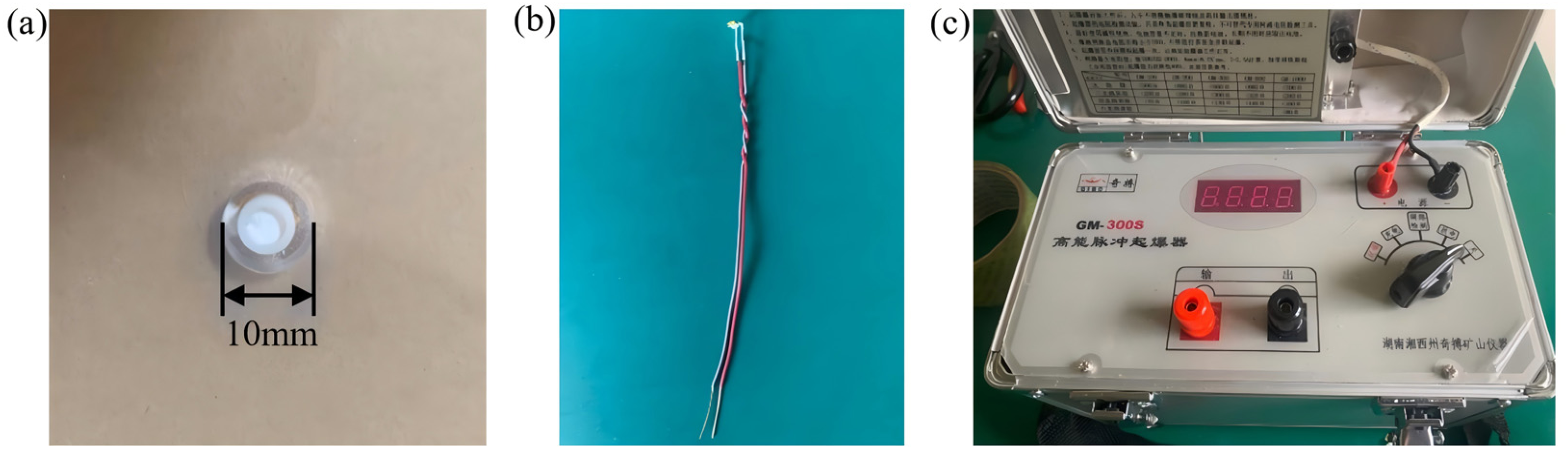
(a) Schematic diagram of the slotted cartridge; (b) detonator probe; and (c) detonator.
Future 8200Pro resin parameters.

Main detonation parameters of lead azide.

Influence of slot angle on crack distribution
Figure 6(a) presents the explosive outcomes of slotted cartridges at different a. These results demonstrated that slotted cartridges can guide directional crack propagation along the slot direction. Nevertheless, when the a ranged from 90° to 135°, crack tips bent toward the surrounding rock, whereas from 135° to 180°, they bent toward the protective surrounding rock. As the a increased, the angle between the primary cracks remained larger than the a. Additionally, the length of the primary crack increased, while the length of the longest secondary crack decreased. No significant cracks were observed within the non-slot ranges.
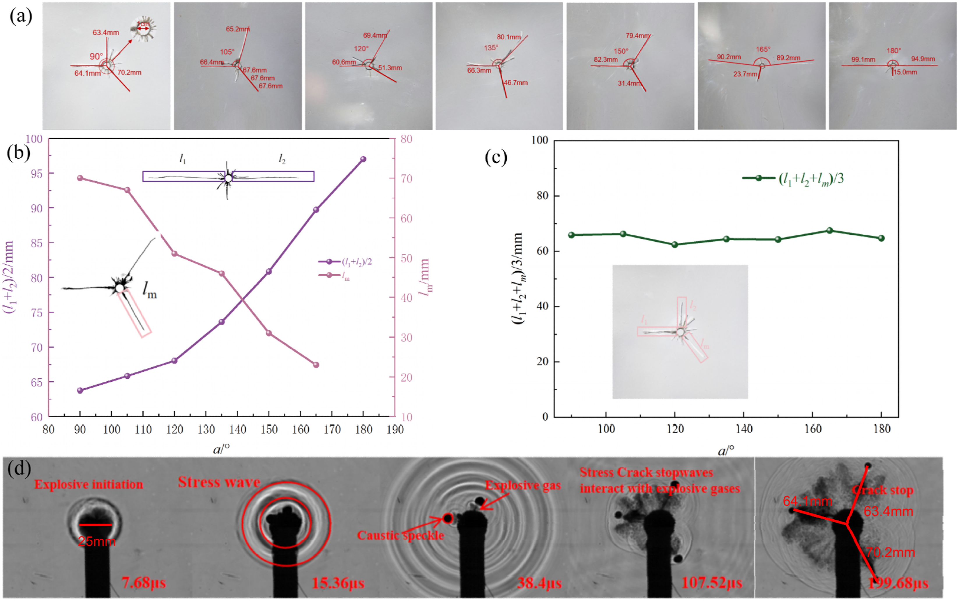
(a) Photos of the PMMA plate after failure; (b) relationship between crack length and a; (c) relationship between average crack length and a; and (d) dynamic evolution of caustic spots at a time interval of 7.68 μs.
We define the left-side primary crack as ll, the right-side primary crack as l2, and the longest secondary crack as lm. Table 4 summarizes the statistical data on the average length of the primary cracks, the length of the longest secondary crack, their ratio, the radius of the fragmented zone r, the number of cracks n, and the angle between the primary cracks a1.
Statistics of blasting-induced cracks.
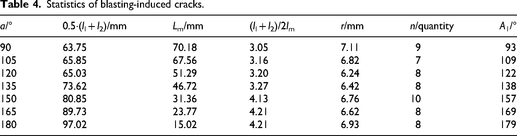
Figures 6(b) and 6(c) demonstrated that as the a increased, the average length of the primary cracks increased, while the length of the longest secondary cracks decreased. The average length of the three cracks, calculated as la = (ll + l2 + lm)/3, remained stable between 60 and 70 mm. This finding suggested that the total work done by the explosive on PMMA was generally consistent, with an error of less than 5%. The mechanism behind this phenomenon is that explosive energy was preferentially released along the slot direction, while some energy converged in the opposite direction of the slot angle. This convergence diminished with increasing a, resulting in a decrease in the length of the longest secondary cracks. When the a was 90°, the extensive superposition of stress waves from the two primary cracks in the opposing region created a stress concentration zone that drove the longest secondary cracks to extend to 70.18 mm. Conversely, when the a was 180°, the weaker superposition of stress waves led to a decrease in secondary crack length to 15.02 mm. This was due to the increased proportion of energy from the primary cracks, significantly weakening the energy available for the secondary cracks.
Figure 6(d) illustrates the crack propagation process captured by a high-speed camera at a time interval of 7.68 μs for a slot angle of 90°. At 7.68 μs, the explosive energy from the detonation of lead azide propagated as stress waves. At 15.36 μs, the stress wave propagated outward to form circular stripes, while caustic spots appeared at the crack tips. The impact of the explosive stress waves caused the medium to exhibit a convex lens effect, which converged light to create bright lines. At 38.4 μs, directional cracks developed along the slot direction, while caustic spots appeared at the crack tips. The stress concentration caused the medium to behave like a concave lens, which deflected light to create shadow regions. The caustic spots aligned at approximately 90° to the blast hole center, while explosive gases diffused along the fractures. At 107.52 μs, the cracks propagated due to the combined effects of stress waves and explosive gases. The diffusion range of explosive gases did not exceed the crack length. By 199.68 μs, the diameter of caustic spots at the crack tips decreased, and crack propagation ceased.
Influence of slot angle on the dynamic propagation characteristics of the primary cracks
The coordinates of the crack tips were measured using CAD. The crack propagation speed was calculated using the following formula:
The dynamic stress intensity factor is correlated with the maximum diameter of the caustic spot. The calculation formula is as follows (Zhang and Wang, 2018):
Figure 7(a) illustrates the variation in crack propagation speed over time. The overall speed of the blasting-induced primary crack tip increased with the a, while the duration until crack arrest was prolonged. Conversely, as the a increased, the speed of the longest secondary crack tip gradually decreased, and the longest secondary crack exhibited a progressively faster cessation of propagation. The changes in a resulted in opposing trends for primary and longest secondary cracks. This observation demonstrated a competitive distribution of energy.
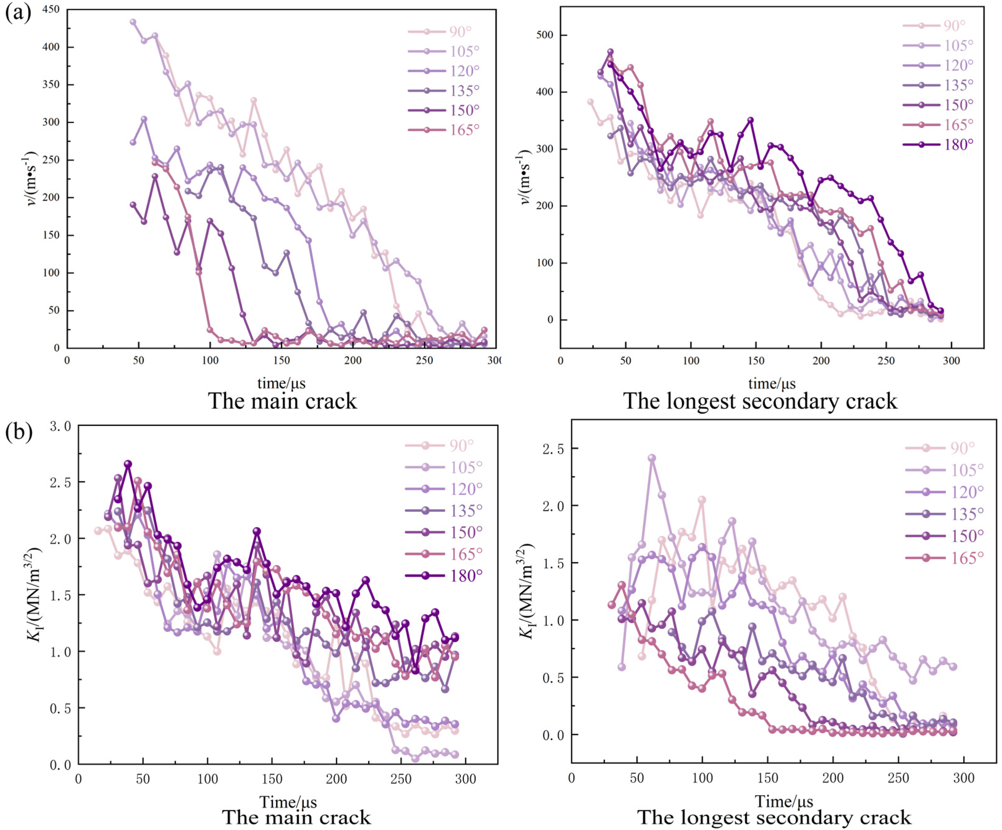
(a) Variation of propagation speed of the primary cracks over time; and (b) variation of KI over time.
Figure 7(b) depicts the variation of the KI over time. The KI reached 2.8 MN·m3/2) at 180°, which is significantly higher than 1.9 MN·m3/2 at 90°. This finding confirmed that the driving force for primary crack propagation intensified with increasing a, while the KI at the tips of the longest secondary cracks gradually decreased and approached zero more quickly. According to Griffith's criterion for crack energy, the ongoing propagation of cracks resulted in continuous energy consumption during the formation of new crack surfaces, which eventually led to crack arrest.
Influence of slot angle on medium damage features
The slotted cartridge controls the directional propagation of cracks through the slot. The difference between the a and the angle between the primary cracks a1 is defined as Δa. Table 4 indicates that Δamax was 7° at 150°, with smaller deviations observed at other angles. This suggested that different a consistently induced directional cracks. Figure 6(d) showed that stress waves traveled faster than crack propagation. According to energy theory, the initiation and propagation of initial cracks are accompanied by a redistribution of energy, while stress waves continue to propagate during the crack propagation process. Figure 8(a) demonstrated that the stress waves generated by the two primary cracks superposed to form a stress concentration zone, which directly impacted the propagation of the longest secondary crack. Assuming that the diameters of the stress waves from the two primary cracks are equal (i.e., d1 = d2, see Figure 8(b)), the angle between the primary crack 1 and the longest secondary crack is a1, and the angle between the primary crack 2 and the longest secondary crack is a2. Additionally, a1 = a2, and the angles exhibit a linear relationship with a. During the charging process of the slotted cartridges, factors such as eccentric decoupling and charge density resulted in inconsistent displacements of the primary cracks in the two slot directions. This led to discrepant stress wave magnitudes at the slots. Assuming that d2 = 2d1 (see Figure 8(c)), the angle between the cracks decreased as the a increased, and the longest secondary crack deflected towards the longer secondary crack direction. Meanwhile, the deflection angle decreased with increasing a. Assuming that when a was 90°, if d1 remained constant while d2 gradually increased (see Figure 8(d)), then a1” increased as the d2/d1 ratio rose, while a2” decreased with increasing d2. Consequently, the deflection angle increased with increasing a.
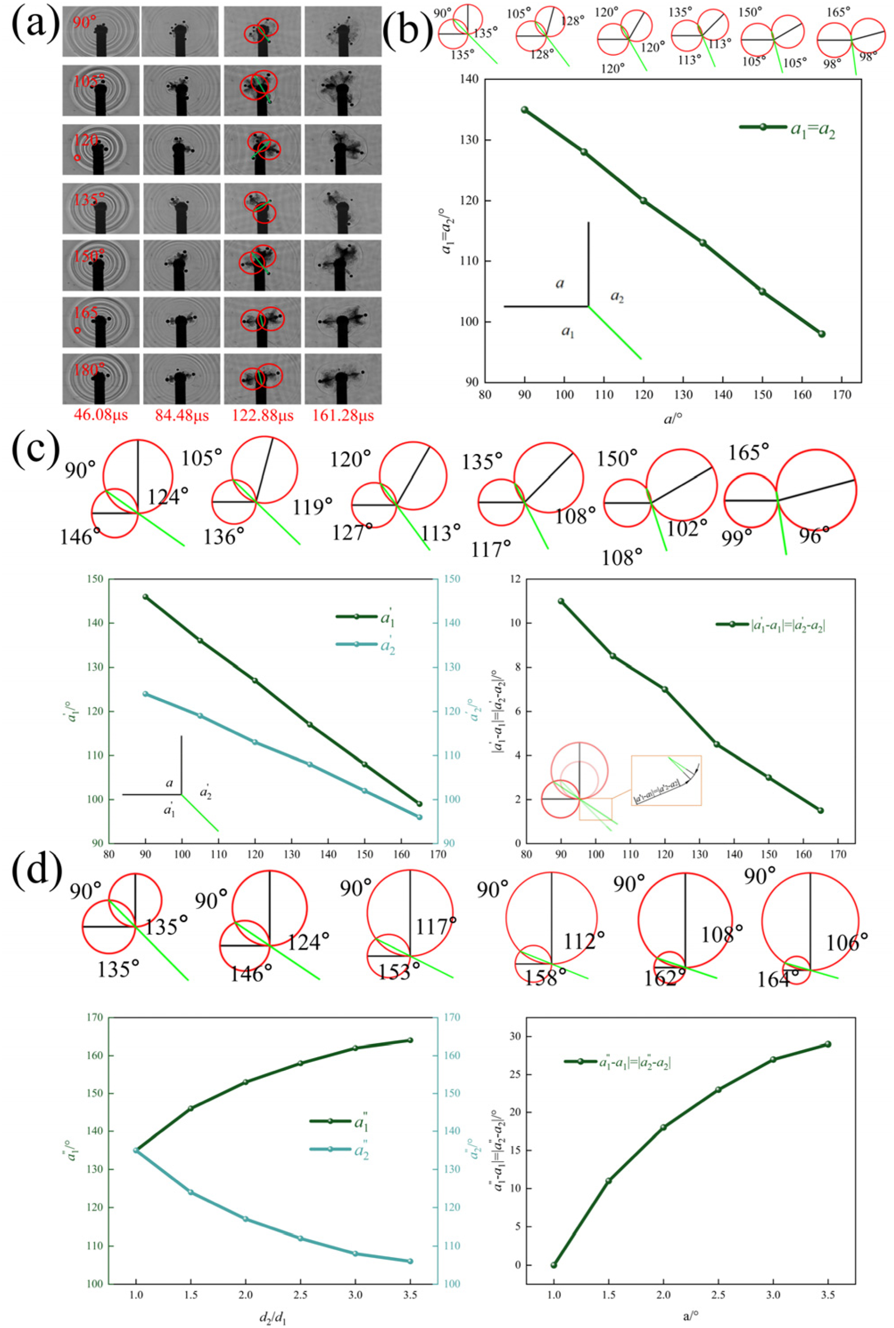
(a) Schematic diagram stress wave superposition; (b) d1 = d2, variation of the angle between the cracks with a; (c) 2d1 = d2, variation of the angle between the cracks with a; and (d) variation of the ratio of the primary crack lengths with a at a constant a and a variable d2.
The post-explosion images of the specimens in Figure 6(a) were binarized (Figure 9(a)) and segmented into various zones based on a ranges: 90° to 135° are mapped in Figure 9(b), while 150° to 180° is presented in Figure 9(c). The damage value is defined using the following formula (Xiao et al., 2024b):
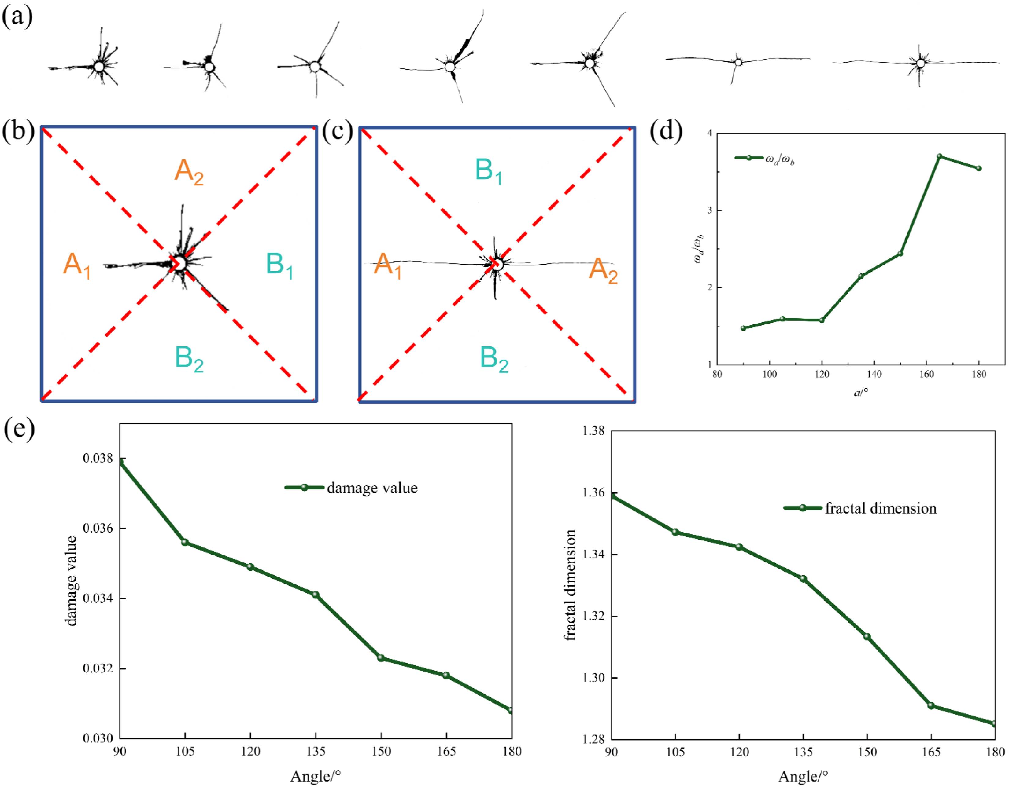
(a) Binarized images; (b) division of zones at 90°, 105°, 120°, and 135°; (c) division of zones at 150°, 165°, and 180°; (d) relationship between the ratio of damage values in zone A to zone B and the a; and (e) relationship among F, a, and w.
Since the damage evolution process of rock exhibits distinct fractal characteristics, the 2D damage evolution process of rock can be considered as the evolution process of fractal dimension. This study employed the box-counting method to calculate the fractal dimensions of various zones after blasting (Yang et al., 2023b).
Based on the principle of box-covering method, the box-counting dimensions of various zones were calculated using a MATLAB program.
Damage values for different zones were calculated using MATLAB, as presented in Figure 9(d). As the a increased, the ratio of damage values in zone A to zone B increased, demonstrating improved control of damage to the surrounding rock. Fractal dimension calculations were also conducted on the binarized images in Figure 9(a). The results for damage values and fractal dimensions are illustrated in Figure 9(e). Revealed that as *a* increased, the reduction in secondary cracks led to gradual decreases in both damage values and fractal dimensions.
Discussion
2D experimental results indicated that when the a was 90°, the length of the secondary cracks reached 70.18 mm, and the w in the non-slot region was greater. This scenario is suitable for engineering applications that require enhanced localized fragmentation, such as in the junction between the inverted arch and the sides, where improved fragmentation effects are needed through secondary cracks. When the a increased to 180°, the length of the primary cracks significantly increased to 97.02 mm, while the length of the secondary cracks decreased to 15.02 mm. This scenario demonstrates excellent directionality and is suitable for regions requiring high-profile smoothness, such as vaults and arch waists, where over-excavation must be controlled.
2D experimental results indicated that the length of the primary cracks increased as the a rose, and the angle between the primary cracks deviated slightly from the slot angle, with a maximum deviation of 7°. This indicated that the a can be effectively utilized to accurately predict the extent of primary crack propagation. In practical engineering, the spacing of blast holes can be optimized based on the designed profile dimensions and primary crack lengths. This approach prevents profile discontinuities caused by excessive spacing and minimizes energy waste from insufficient spacing, thereby improving the utilization of blast holes.
3D model tests on the directional fracture capability of the slotted cartridge at different slot angles
While 2D dynamic caustic experiments can effectively reveal the propagation patterns of blasting-induced cracks and the evolution of stress fields within a plane, actual engineering scenarios involve a 3D stress environment for the rock mass. The propagation of cracks is influenced by spatial constraints, which results in differences between their 3D behaviors and the observations from 2D planes. To validate the applicability of the 2D experimental findings in 3D scenarios and to more realistically simulate the 3D crack propagation during engineering blasts, this section conducted 3D PMMA column model experiments. CT scanning technology allows for 3D reconstruction and quantitative characterization of cracks, which reveals how a affects directional fracture capability within a 3D stress field. This provides a more realistic experimental basis for practical engineering applications.
Experimental scheme
To investigate the impact of a on directional fracture capability in 3D media, PMMA specimens with a diameter of 100 mm and a height of 100 mm were fabricated. A central axis was pre-drilled with a 4 mm diameter and 60 mm deep hole, into which slotted pipes at angles of 90°, 120°, 150°, and 180° were inserted. The charge for each blast hole was 50 mg (lead azide), and the sealing length was set at 20 mm. A schematic of the charging process is illustrated in Figure 10.
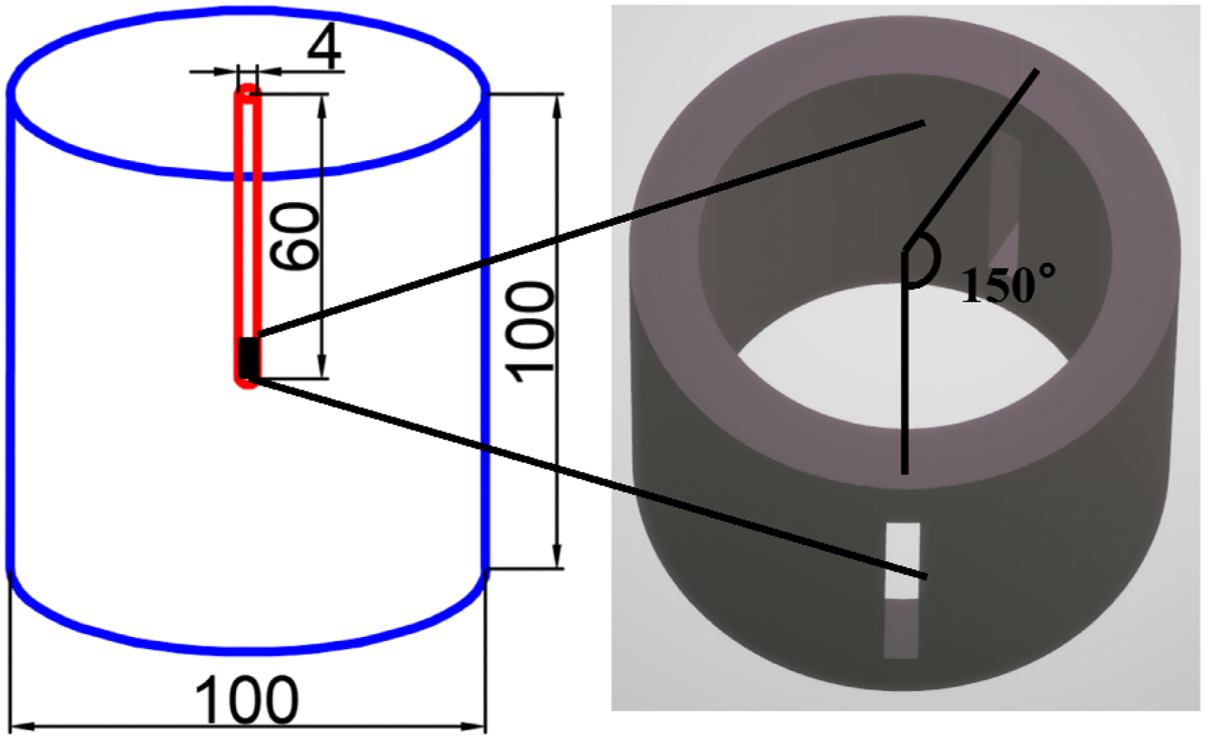
Schematic of the 3D PMMA column model.
CT scanning and 3D reconstruction of PMMA
The specimen was scanned using an ACTIS300-320/225 CT scanner at a scanning voltage of 280 kV. The scanning range was from 0 to 110 mm, with a slice thickness of 0.1 mm. Consequently, a total of 1100 images with a resolution of 1024 × 1024 pixels were obtained. To minimize edge light beam hardening and specimen platform interference, a cylindrical region measuring 80 mm in height and 90 mm in diameter was selected from the middle of the specimen for analysis purposes (Figure 11).
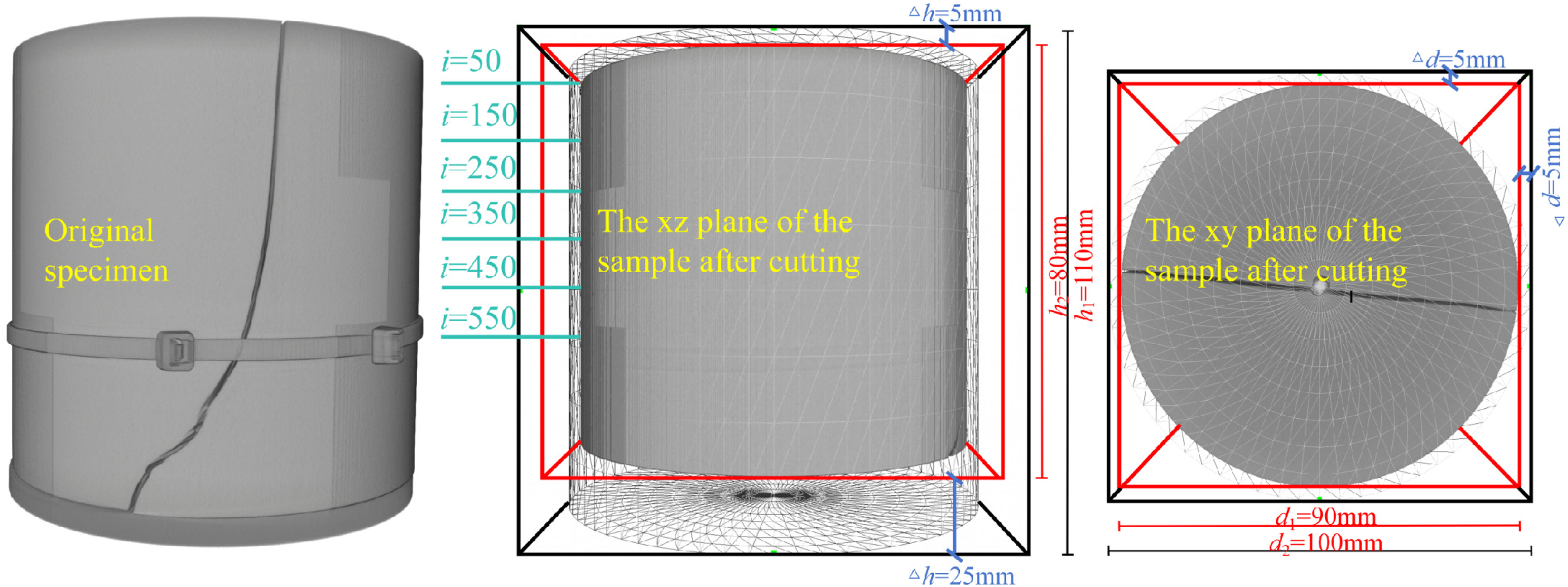
Schematic for dividing the total analysis region of sample.
CT scanning data were processed, and slice images were extracted from the specified locations shown in Figure 11, as illustrated in Figure 12(a). The slice images clearly exhibited various positions from the bottom to the top of the blast hole. Moreover, all cracks extended along the direction of the slots. Cracks were extracted using threshold segmentation, as shown in Figure 12(b). Figures 12(c) and 12(d) present the 3D reconstruction of cracks at different a.
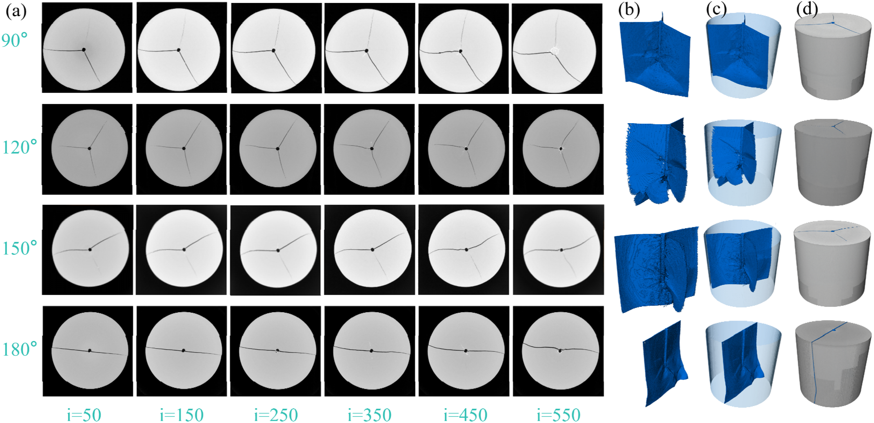
(a) Slice image; (b) crack; (c) 3-D reconstruction of cracks; and (d) 3-D reconstruction of cracks.
Influence of slot angle on medium damage features
3D reconstruction results were utilized to quantitatively analyze damage characteristics of the post-explosion medium using Avizo Professional image processing software. The core evaluation metrics selected include the fractal dimension (F), the surface area of cracks (S), and the damage value (w). The F describes the complexity of the crack spatial distribution, with a range of 2 to 3. The S represents the total unfolded area of all cracks in 3D space, which directly reflects the physical extent of crack propagation. The w is defined as the ratio of crack volume (Vc) to the total volume of the specimen (Vt). This parameter quantifies the overall damage to the medium caused by the explosion.
Experimental results presented in Table 5 indicated that as the a increased from 90° to 180°, the F decreased from 2.10241 to 2.03731, while the S decreased from 2.79166e + 10 μm2 to 1.93351e + 10 μm2, and the w dropped from 0.01324 to 0.00859. This trend closely aligns with the conclusions derived from the 2D dynamic caustic experiments. As the a increased, the explosive energy was primarily released along the slot direction, which allowed the primary cracks to fully propagate in this direction, while secondary cracks in non-slot regions struggled to develop due to reduced energy distribution. This resulted in a shift in crack distribution from a multi-directional dispersion to a single-directional concentration. This is the core reason for the reductions in F, S, and w.
Summary of F, S, and w.

Specifically, when the a was 90°, the F reached its maximum of 2.10241, while both the S and w were also relatively high. This observation suggested that, in addition to the primary cracks along the slot, numerous disorganized secondary cracks existed in non-slot regions. The overall damage exhibited weak directionality and a broad range. In contrast, when the a was 180°, the F was at its minimum of 2.03731, while both the S and w were significantly reduced. This indicated that cracks primarily propagated along the slot direction, and nondirectional damage was effectively suppressed. This case yielded optimal directional fracture performance. The a of 150°, which serves as a transitional angle, yielded parameter values that fell between those of 90° and 180°. This further confirms that a affects damage characteristics by regulating energy distribution.
The 3D experimental findings support the conclusions from the 2D experiments that an increased a improves directional fracture capability and decreases unnecessary damage. Moreover, the quantifiable parameters illustrate the evolution of damage from a dispersed state in 3D space to a concentrated directional form. This provides crucial experimental support for understanding the functioning mechanisms of slotted cartridges within the 3D stress environments encountered in practical engineering (Figure 13).
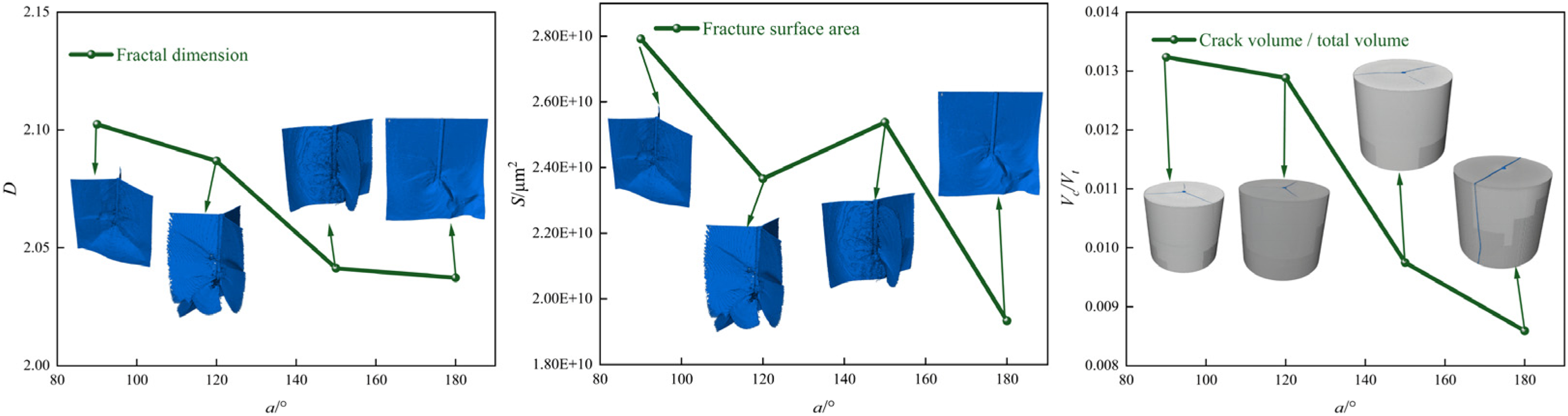
Relationship among F, S, w, and a.
Field tests
Project overview
The tunnel has a width of 12.43 m and a height of 7.41 m. It was excavated using a full-section method without an inverted arch. The cross-sectional perimeter is 46.56 m, and the cross-sectional area is 76.35 m2. The rock primarily consists of dolomitic limestone with well-developed fractures. A total of 125 blast holes were arranged in the tunnel section for conventional blasting. A two-stage, two-step wedge-shaped slot excavation method was employed. The designed excavation cycle length is 4 m, and the blasthole layout is shown in Figure 14(a). A YT-28 pneumatic rock drill was employed to drill holes with diameters ranging from 43 mm to 45 mm. The control group was set up to compare the blasting effect of ordinary cartridges and slotted cartridges in the surrounding holes. The type II emulsion explosive with specifications of Φ32 mm × 300 mm, 300 g per cartridge was used. The distance between the cartridges in the peripheral holes was 30 cm. Four volumes of explosive were installed in a single hole, and the stemming length was 1.2 m. The charge structure is shown in Figure 14(b). The hole spacing of the peripheral hole is 50 cm, and the explosive of the peripheral hole is detonated at the same time. The only difference between the slotted cartridge and the ordinary cartridge is that when the slotted cartridge is used, the explosive needs to be placed in the prepared slotted tube (Figure 14(c), and then the slotted tube and the explosive are placed in the peripheral hole.
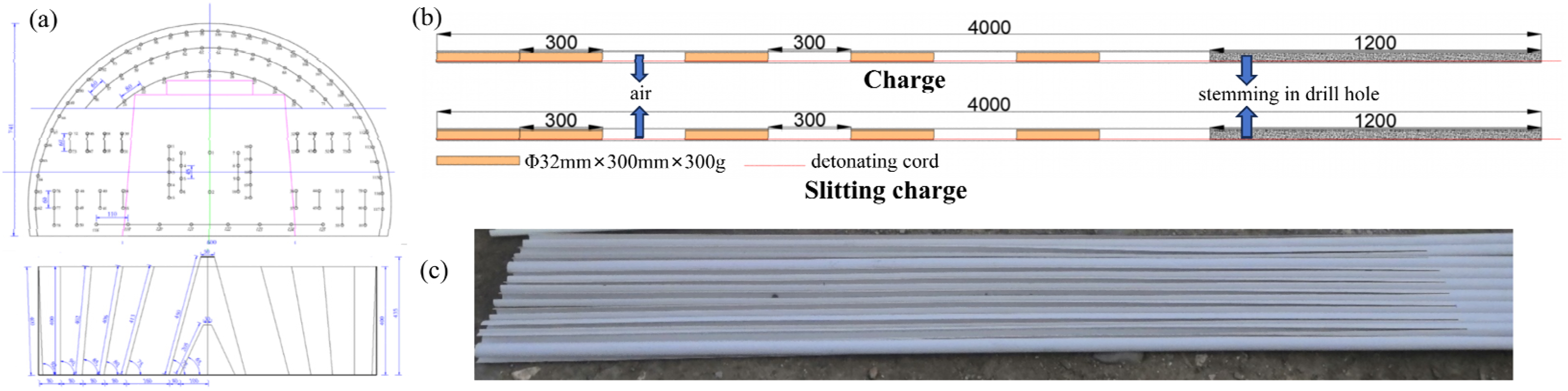
(a) layout of field blast holes (cm); (b) charge structures; and (c) photo of slotted pipe.
Conclusions from the 2D experiments indicated that when the a exceeded 165°, the length of the secondary cracks was less than 15 mm, less damage to surrounding rock. Therefore, strict control of over-excavation is necessary for the vault and arch waist regions. Therefore, slotted pipes with angles of 171° and 167° were selected (both greater than 165°). To strengthen localized fragmentation in the junction between the inverted arch and the sides, a slotted pipe with a 90° angle was chosen due to its ability to produce longer secondary cracks. This selection ensures an accurate match between experimental conclusions and engineering requirements.
Experimental results
Under ordinary cartridge explosive conditions, an under-excavation phenomenon occurred at the tunnel vault, while over-excavation was observed on both sides, resulting in an unsmooth excavation profile. There were no half-hole traces, and the half-hole ratio was 0. The excavation cycle length was 3.3 m, while blast hole utilization rate reached 82.5%, and residual hole depths ranged from 65 to 70 cm. These observations indicated generally poor blasting effectiveness, as illustrated in Figure 15(b). After blasting with slotted cartridges at various angles, the excavation profile's smoothness was significantly improved. The number of half-hole traces around the holes increased to 19, and blast hole utilization rate rose to 92.5%. The residual hole depths at the vault ranged from 5 to 10 cm. The residual hole depth at the left-side inverted arch was 30 cm, while no residual holes were found at the right-side inverted arch. The directional control blasting effect is demonstrated in Figure 15(a). Results of over- and under-excavation from smooth blasting, measured using the on-site profile instrument, are illustrated in Figure 15(c). The use of slotted pipes at different a reduced the over-excavated area per meter from 16.471 to 2.508 m2. Maximum over-excavation decreased from 1.143 to 0.253 m, and average over-excavation dropped from 0.693 to 0.084 m.
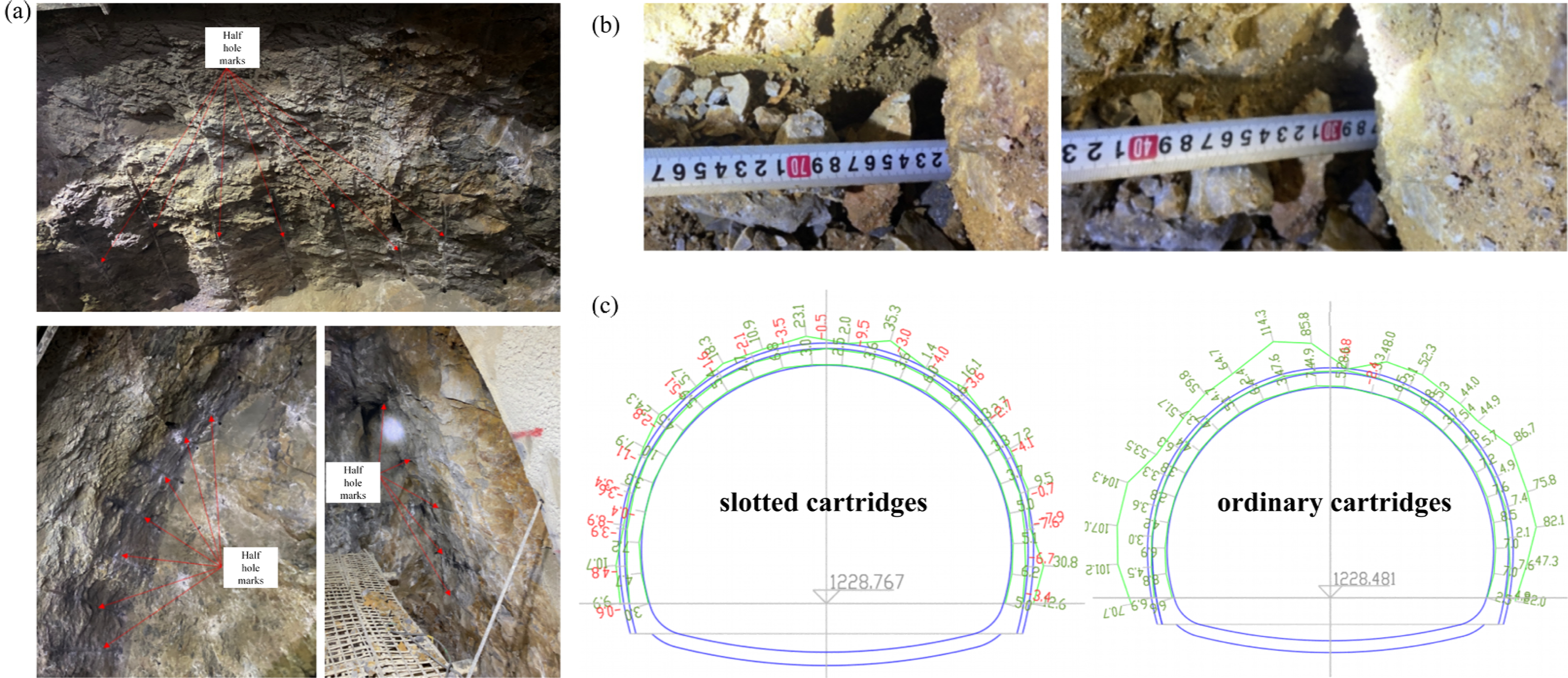
(a) Post-blasting effect; (b) depth of residual holes; and (c) illustration of over- and under-excavation.
The results confirmed that slotted pipes with larger slot angle have shorter secondary cracks and excellent directionality, which makes them suitable for over-excavation control. The slotted pipes at 90°, capable of producing longer secondary cracks, meet the requirements for local fragmentation.
Conclusions
In this study, the directional fracture capabilities of slotted cartridges with varying slot angles were systematically investigated utilizing a comprehensive approach that integrates theoretical analysis, two-dimensional (2D) and three-dimensional (3D) physical experiments, and in-situ field tests. The main conclusions drawn are as follows:
Based on the detonation wave theory and the thin-walled cylinder assumption, the hole wall pressure at the slot and non-slot is derived, and compared with the numerical simulation results, the error is less than 7%. The results from the 2D dynamic caustic experiments demonstrated that different a consistently induced directional cracks; however, longer secondary cracks tended to occur when the a was less than 165°. As the a increased, the length of the primary cracks gradually increased, while the length of the longest secondary crack gradually decreased. The magnitude of superimposed stress waves generated during the propagation of the two primary cracks determined the length of the longest secondary crack. The size of stress waves altered the angle between the longest secondary crack and the primary cracks. Additionally, a is inversely proportional to the damage in the non-slot regions. 3D PMMA experiments further validated the results obtained from the 2D dynamic caustic experiments. As the a increased, the F, w, and S all progressively decreased. Field applications demonstrated that a values of 171° and 167°, which matched the profile, reduced the over-excavation area from 16.47 m2 to 2.51 m2, while the utilization rate of blast holes increased from 82.5% to 92.5%.
Footnotes
Acknowledgements
The author(s) disclosed receipt of the following financial support for the research, authorship, and/or publication of this article: This research was financially supported by The National Key Research and Development Program (2021-008), Wuhan key Research and Development Program (2024050802030155), 2024 Chutian Talent Plan—Science and Technology Innovation Team Project.

CRediT authorship contribution statement
Qiang Li: Formal analysis, Investigation, Writing-original draft. Jinshan Sun: Funding acquisition, Methodology, Validation. Xianqi Xie: Project administration, Supervision. Yongsheng Jia: Resources, Supervision. Nan Jiang: Conceptualization, Writing - review & editing. Xianglong Li: Resources, Validation.
Funding
The authors disclosed receipt of the following financial support for the research, authorship, and/or publication of this article: This work was supported by the 2024 Chutian Talent Plan—Science and Technology Innovation Team Project, Wuhan key Research and Development Program, The National Key Research and Development Program, (grant number 2024050802030155, 2021-008).
Declaration of conflicting interests
The authors declared no potential conflicts of interest with respect to the research, authorship, and/or publication of this article.
Data availability statement
Data will be made available on request.