This paper is concerned with a delayed non-fragile control scheme for an offshore steel jacket platform subject to self-excited nonlinear hydrodynamic force and external disturbance. By intentionally introducing a time-delay into the control channel, a delayed robust non-fragile controller is designed to reduce the vibration amplitudes of the offshore platform. The positive effects of the time delays on the non-fragile control for the offshore platform are investigated. It is shown through simulation results that (i) the proposed delayed non-fragile controller is effective to attenuate the vibration of the offshore platform; (ii) the control force required by the delayed non-fragile controller is smaller than that required by the delay-free non-fragile controller; (iii) the time delays can be used to improve the control performance of the offshore platform.
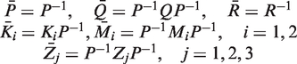
Throughout this paper, all of the matrices are real matrices. The superscript ‘T’ denotes the transpose of a matrix or vector. For an invertible matrix, the superscript ‘–1’ means the inverse of the matrix. For symmetric matrices P and Q, the notation (respectively, means that the matrix P – Q is positive definite (respectively, semi-positive definite). Here denotes the space of square integrable vector functions on and I is the identity matrix of appropriate dimensions. Matrices, if the dimensions are not explicitly stated, are assumed to have compatible dimensions for algebraic operations. For simplicity, the symmetric term in a symmetric matrix is denoted by , e.g., .
1. Introduction
Offshore steel jacket platforms supported by pile foundations are the most common kind of offshore structures, which are used for deep-water applications for the drilling, production, and storage of ocean deposits. Located in the marine environment, offshore platforms are subject to many kinds of loadings, such as wave, flow, current, and earthquake (Wilson, 2002; Kim, 2009; Chen, 2011). On the other hand, sophisticated structures generally induce self-excited nonlinear hydrodynamic force and make themselves large deformations due to nonlinear responses (Terro et al., 1999). These loadings may lead to tremendous vibration, which may damage the safety of the offshore platform and cause the problem of uncomfortable environment of staying. Therefore, vibration control of the offshore platforms becomes one of the major concerns in the area of engineering applications.
The theory and practice of active control have been successfully applied to the control of engineering structures (Chen et al., 2010a; Li et al., 2010; Korkmaz, 2011; Braghin et al., 2013; Chen, 2013). During the past decade, several control strategies have been investigated for active control of offshore platforms. For example, optimal-control-based schemes have been proposed to reduce the oscillation amplitudes of offshore steel jacket platforms (Li et al., 2003; Luo and Zhu, 2006). For an offshore steel jacket platform with an active tuned mass damper (TMD) mechanism, a nonlinear control scheme and a robust state feedback linear control scheme have been developed to reduce vibration amplitudes of the system (Zribi et al., 2004). Taking the uncertainties of system’s parameters into account, a robust integral sliding mode control scheme has been proposed to reduce oscillation amplitudes of an offshore platform (Zhang et al., 2013). More recently, Zhang et al. (2013) developed a robust sliding mode control strategy to attenuate the vibration of the offshore platform subject to both self-excited nonlinear wave force and external disturbance. Simulation results have shown that the active control schemes aforesaid are effective to deal with the vibration problem of offshore steel jacket platforms. It should be mentioned that controller design mentioned above is based on an implicit assumption that the control input can be exactly realized without any controller perturbations. However, physical limitations and component aging or failure caused by environmental temperature changes may induce certain degree of controller perturbation, which may result in poor performance or even instability of the closed-loop system. As is well known, non-fragile control is efficient to deal with perturbation of controller gain and external disturbance, and it has been applied in some engineering practice. For instance, Du et al. (2005) and Li et al. (2012) investigated non-fragile control schemes to improve the control performance of active suspension systems. Inspired by Du et al. (2005) and Li et al. (2012), developing a non-fragile controller to reduce the oscillation amplitudes of the offshore platform subject to parameter uncertainty, external disturbance and controller gain variation is the first motivation of the current study.
Note that time delays are unavoidable in many practical control systems, and they are generally regarded as a main factor to affect the stability and performance of the systems. The analysis and synthesis of time-delay systems have been investigated extensively in recent years, see, e.g., Gu et al. (2001), Han (2002, 2009), Peng and Tian (2009), Chen et al. (2010b), Li and Tang (2010), Zhang and Han (2012), Chen et al. (2012), and Song and Sun (2012) and references therein. However, in some circumstances, properly introducing a time delay into the control channel may stabilize and improve the control performance of some systems. For example, a delayed output feedback controller has been developed to stabilize a system which cannot be stabilized without time delay (Michiels et al., 2004). Salarieh and Alasty (2008) applied a delayed feedback control scheme to a chaotic spinning disk model for chaos elimination. Atay (2002) developed a delayed position feedback control of oscillatory behavior to annihilate limit cycles and stabilize the origin. Delayed feedback control schemes have been applied to the active vibration control of structures (Udwadia and Phohomsiri, 2006; Jnifene, 2007) and oscillator systems, see, e.g., Maccari (2003, 2008), Li et al. (2006), Chatterjee (2008), and Yang and Sun (2010). Chatterjee et al. (2007) used a time-delay factor as a key factor for preventing the outbreak of a disease. Specifically, Zhang et al. (2011) presented a delayed dynamic output feedback control scheme to control an offshore platform. It is shown through simulation results that the delayed dynamic output feedback control scheme can effectively improve the control performance. However, the obtained maximum time delay on the active control for the offshore platform is less than 0.11 seconds, which is too small from the point of view of controller implementation (Robinett et al., 1998). To design a new delay-dependent control scheme with a larger time-delay than that used by Zhang et al. (2011) to attenuate the vibration of the offshore steel jacket platform is the second motivation of this paper.
In this paper, we will propose a delayed non-fragile control scheme for an offshore platform subject to parameter uncertainties, self-excited nonlinear hydrodynamic force and external disturbance. By purposefully introducing a proper time delay into the control channel, we will develop a robust delayed non-fragile control scheme to attenuate the vibration of the offshore platform, and thereby improve the control performance of the offshore platform. In the simulation results, we will compare the delayed non-fragile control scheme with the delay-free non-fragile control scheme from two aspects: controlled oscillation amplitudes and required control cost. As a special case of the delayed non-fragile control scheme, we will also compare the delayed state feedback control scheme with a nonlinear control scheme (Zribi et al., 2004), a delayed output feedback control scheme (Zhang et al., 2011) and an integral sliding mode control scheme (Zhang et al., 2012), respectively.
2. Problem formulation
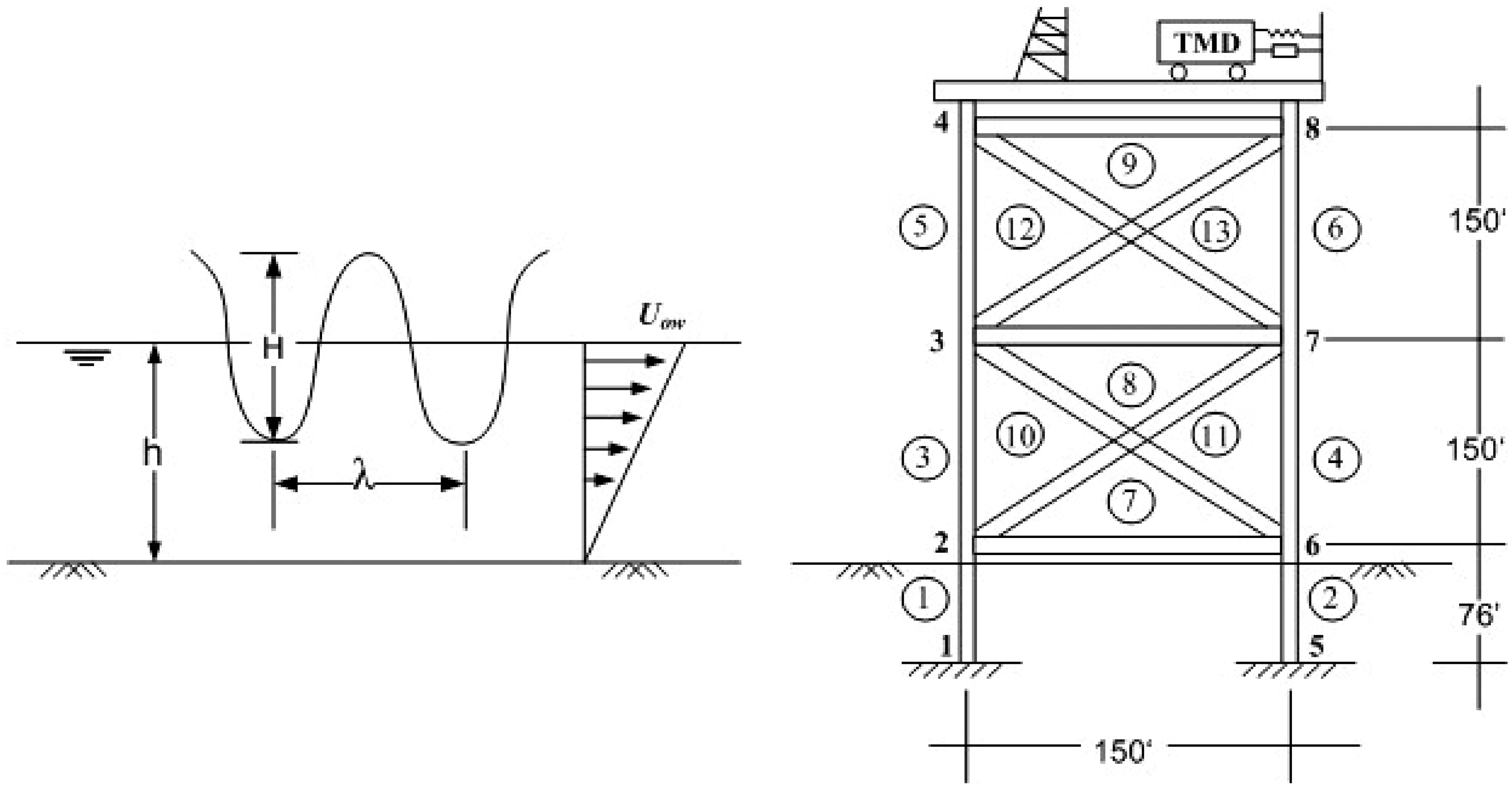
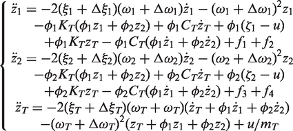
Consider an offshore steel jacket platform with an active TMD mechanism shown in Figure 1 (Terro et al., 1999; Zribi et al., 2004). An active TMD is located on the top of the offshore platform and connected to a hydraulic servo mechanism. The motion of the TMD is influenced by the motion of the platform and the operation of the hydraulic servo mechanism. The nonlinear self-excited hydrodynamic force acts on the offshore platform. Taking the perturbations of the natural frequencies and the damping ratios of the first two modes of vibration and the TMD into account, the motion equation of the first two modes of vibration with the coupled TMD can be expressed as
where z1 and z2 are the generalized coordinates of vibration modes, respectively; zT is the horizontal displacement of the TMD; and are the damping ratios in the first two modes of vibration, and and are the time-varying perturbations of the damping ratios in the first two modes of vibration, respectively; and are the natural frequencies of the first two modes of vibration, and and are the time-varying perturbations of the natural frequencies of the first two modes of vibration, respectively; is the damping ratio of the TMD, and is the time-varying perturbation of the damping ratio of the TMD; and are the contributions of first two modes shapes; CT, mT and KT denote the damping, the mass and the stiffness of the TMD, respectively; is the natural frequency of the TMD, and is the time-varying perturbation of the natural frequency of the TMD; fi () are nonlinear self-excited hydrodynamic force terms; and are the external disturbance acting on the first and the second modes of the offshore platform, respectively; u is the control action of the system.
An offshore steel jacket platform with TMD. Reproduced with kind permission from Elsevier (Terro et al., 1999).
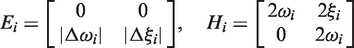
Suppose that and are the maximum perturbation bounds of the natural frequencies and the damping ratios of the vibration modes and the TMD, respectively. Let
and
Denote
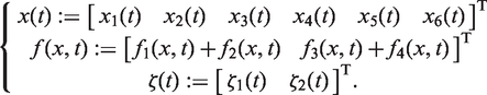
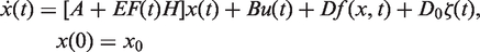
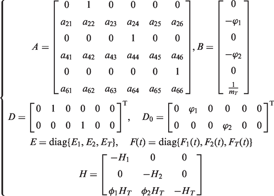
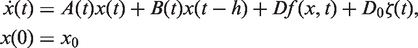
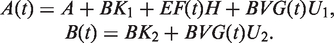
Then, by ignoring the higher-order terms and , the dynamic equation (1) can be written as
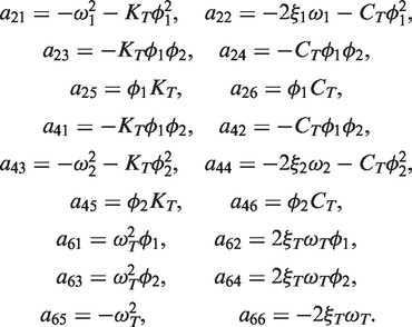
where
with
x0 is the initial value; and the time-varying uncertainty matrix F(t) satisfies
It is assumed that the external disturbance . As demonstrated by Zribi et al. (2004), the nonlinear self-excited wave force is uniformly bounded and satisfies a cone-bounding constraint
with μ a positive scalar.
Remark 1
If we do not consider the external disturbance, i.e. , in this case, the dynamic model (5) reduces to that of Zhang et al. (2012). Furthermore, if we do not consider the perturbations of the natural frequencies and the damping ratios of the first two modes of vibration and the TMD, the model (5) reduces to that of Zribi et al. (2004) as
The control output equation is given by
where C1 and D1 are problem-dependent constant matrices with appropriate dimensions.
In this paper, we will design a delayed robust non-fragile control law such that
under the designed control law, the system (5) with is robustly stable; and
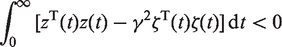
under the zero initial condition, the performance
of the resulting closed-loop system is guaranteed for nonzero and a prescribed .
In what follows, we need the following assumption.
Assumption 1
The matrixD1 in the outputequation (10) and the performance level γ are assumed to satisfy the constraint as
3. Delayed non-fragile controller design
In this section, we develop a delayed robust non-fragile control scheme to control the offshore steel jacket platform.
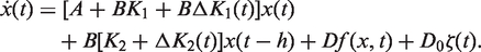
The delayed robust non-fragile control law is designed as
where K1 and K2 are gain matrices to be determined, is the intentionally introduced time delay, and
with V, U1 and U2 are known matrices with appropriate dimensions, is an unknown time-varying matrix satisfying
The following proposition provides a sufficient condition for the existence of the delayed robust non-fragile control law (12).
Proposition 1
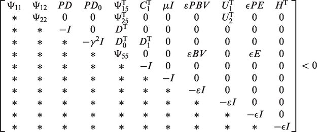
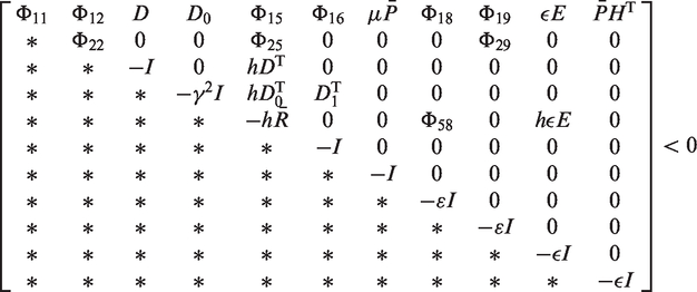
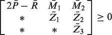
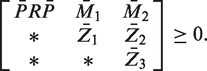
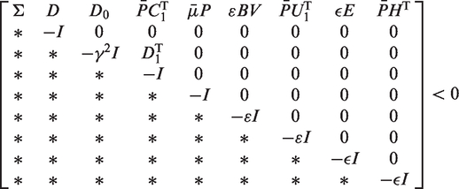
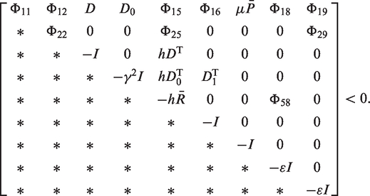
Under Assumption 1, for given scalars, and, the closed-loop system (15) with is robustly stable, and the performance (11) is guaranteed, if there exist matrices,,,M1,M2,,Z2,, matricesK1 andK2, and scalars and such that
and
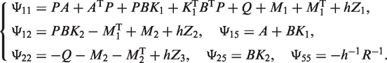
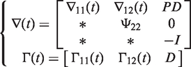
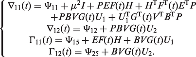
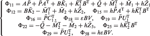
where
Proof
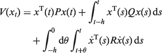
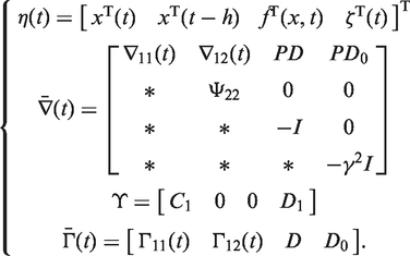
Choose a Lyapunov–Krasovskii functional as
where , , and .
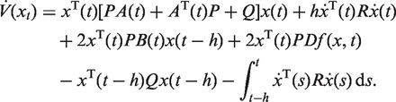
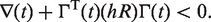
First, we consider the robust stability of closed-loop system (15) with . Taking the derivative of with respect to t along the trajectory of system (15) yields
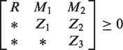
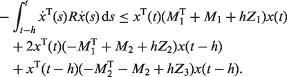
By Lemma 2 of Zhang et al. (2005), for any matrices , M1, M2, , Z2 and satisfying the constraint (17), we have
Then, a sufficient condition for robust stability of system (15) with is that there exist matrices , , , , , matrices K1 and K2 such that (17) and
By Schur complement and S-procedure, matrix inequality (25) holds if there exist scalars and such that
which can be derived from the matrix inequality (16). It indicates that if the matrix inequalities (16) and (17) hold, then the closed-loop system (15) with is robustly stable.
We now prove that the performance (11) is guaranteed for non-zero and a prescribed . Taking the derivative of with respect to t along the trajectory of (15), and combing with equation (10), after simple manipulations, one yields
where
If the matrix inequalities (16) and (17) hold, by using Schur complement and S-procedure again, one yields
which leads to
Since under zero initial condition, integrating both sides of equation (30) from 0 to ∞, we have
which means that the performance (11) is guaranteed. This completes the proof.
Note that there exist nonlinear terms in matrix inequality (16). We give an equivalent form of Proposition 1, where the sufficient condition for the existence of the delayed robust non-fragile control law is formulated in the form of a linear matrix inequality.
Proposition 2
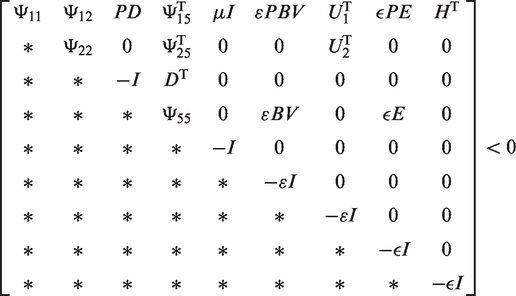
Under Assumption 1, for given scalars, and, the closed-loop system (15) with is robustly stable, and the performance (11) is guaranteed, if there exist matrices,,,,,,,, matrices,, scalars and such that
and
where
Moreover, the gain matrices inequation (12) are given by,.
Proof
Pre- and post-multiplying matrix inequality (16) by
On the other hand, the matrix inequality (17) is equivalent to the following matrix inequality
Note that . It is clear that if the matrix inequality (33) holds, then we have equation (35). This completes the proof.
As a special case of the control law (12), we present a delay-free robust non-fragile control law as
In this case, the closed-loop system (15) can be written as
A sufficient condition for the existence of the control law (36) is given by the following corollary, which can be obtained from Proposition 2.
Corollary 1
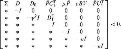
Under Assumption 1, for given scalars and, the closed-loop system (37) with is robustly stable, and the performance (11) is guaranteed, if there exist a matrix, a matrix and scalars and such that
where
Moreover, the gain matrix K1 inequation (36) is given by.
If the system’s parameter uncertainties are not considered, the system (5) reduces to
Substituting equations (12) into (39) yields the closed-loop system as
In order to solve the gain matrices K1 and K2 of the delayed non-fragile control law (12), we present the following corollary, which can be derived from Proposition 2.
Corollary 2
Under Assumption 1, for given scalars, and, the closed-loop system (40) with is asymptotically stable, and the performance (11) is guaranteed, if there exist matrices,,,,,,,, matrices and, and a scalar such that (33) and
Moreover, the gain matrices K1 and K2 inequation (12) are given by,.
Correspondingly, if a delay-free non-fragile control law in the form (36) is utilized to control the nominal system (39), the resulting closed-loop system is given as
To obtain the gain matrix K1, we provide the following corollary.
Corollary 3
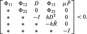
Under Assumption 1, for given scalars and, the closed-loop system (42) with is asymptotically stable, and the performance (11) is guaranteed, if there exist a matrix, a matrix and a scalar such that
Moreover, the gain matrix inequation (36) is given by.
To compare with a nonlinear control scheme (Zribi et al., 2004), a delayed dynamic output feedback control scheme (Zhang et al., 2011) and an integral sliding mode control scheme (Zhang et al., 2012), we consider a delayed state feedback control scheme, which is a special case of the delayed non-fragile control scheme. Let and in equation (12). Then, we obtain a delayed state feedback control law as
In this situation, substituting equations (44) into (9) yields
By Corollary 2, we have the following result.
Corollary 4
For given scalars and, the closed-loop system (45) is asymptotically stable, if there exist matrices,,,,,,,, matrices and such that (33) and
Moreover, the gain matrices K1 and K2 inequation (44) are given by,.
4. Simulation results and discussions
In this section, an example is given to show the effectiveness of the delayed non-fragile control scheme for the offshore steel jacket platform. First, the performance of the nominal system with the delayed non-fragile control scheme and with the delay-free non-fragile control scheme are investigated. Second, the performance of the uncertain system with the delayed robust non-fragile control scheme and with the delay-free one are compared from the controlled oscillation amplitudes of the offshore platform and the required control force. Finally, the delayed state feedback control scheme is compared with a nonlinear control scheme (Zribi et al., 2004), a delayed dynamic output feedback control scheme (Zhang et al., 2011) and an integral sliding mode control scheme (Zhang et al., 2012), respectively.
The parameters of an offshore platform and the data of the wave are taken from Zribi et al. (2004), where the density of steel is kg/m3, the weight of the concrete deck is 6,672,300 N. The wave length, wave height and the water depth are 182.88 m, 12.19 m and 76.2 m, respectively. The density of water is 1025.6 kg/m3, the wave frequency is 1.8 revolutions per second (rps), and the current velocity at the water surface is 0.122 m/s. In (1), the natural frequencies of the first two modes of vibration are rps and rps, respectively. The damping ratios of the first and second modes are , and the shape vectors of the first and second modes are and , respectively. The damping ratio, natural frequency, stiffness, and damping of the TMD are given by , rps, and , respectively.
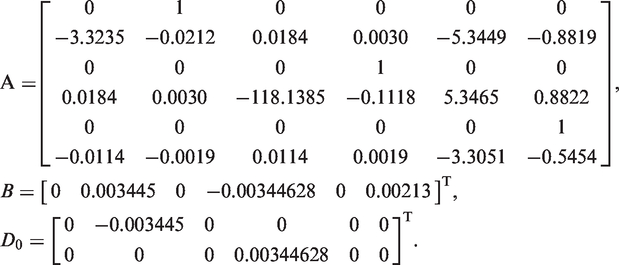
Based on these settings, the matrices A, B and D0 in equation (6) are obtained as
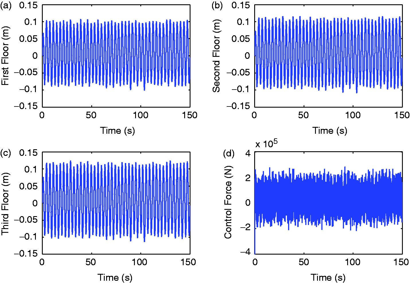
The matrices C1 and D1 in the output equation (10) are given as
The nonlinear self-excited wave force can be computed as in Zribi et al. (2004). The external disturbance acting on the first and second modes are simulated by uniformly distributed random signals with maximum amplitudes N and N, respectively.
4.1. Performance of the nominal system with delayed non-fragile control
For comparison purpose, we first investigate the delay-free non-fragile control. Let , . It is assumed that the parameters of perturbation in controller gain are given by
Then, by Corollary 3, one can obtain a non-fragile controller (NFHC) of the form (36), where the gain matrix K1 is given as
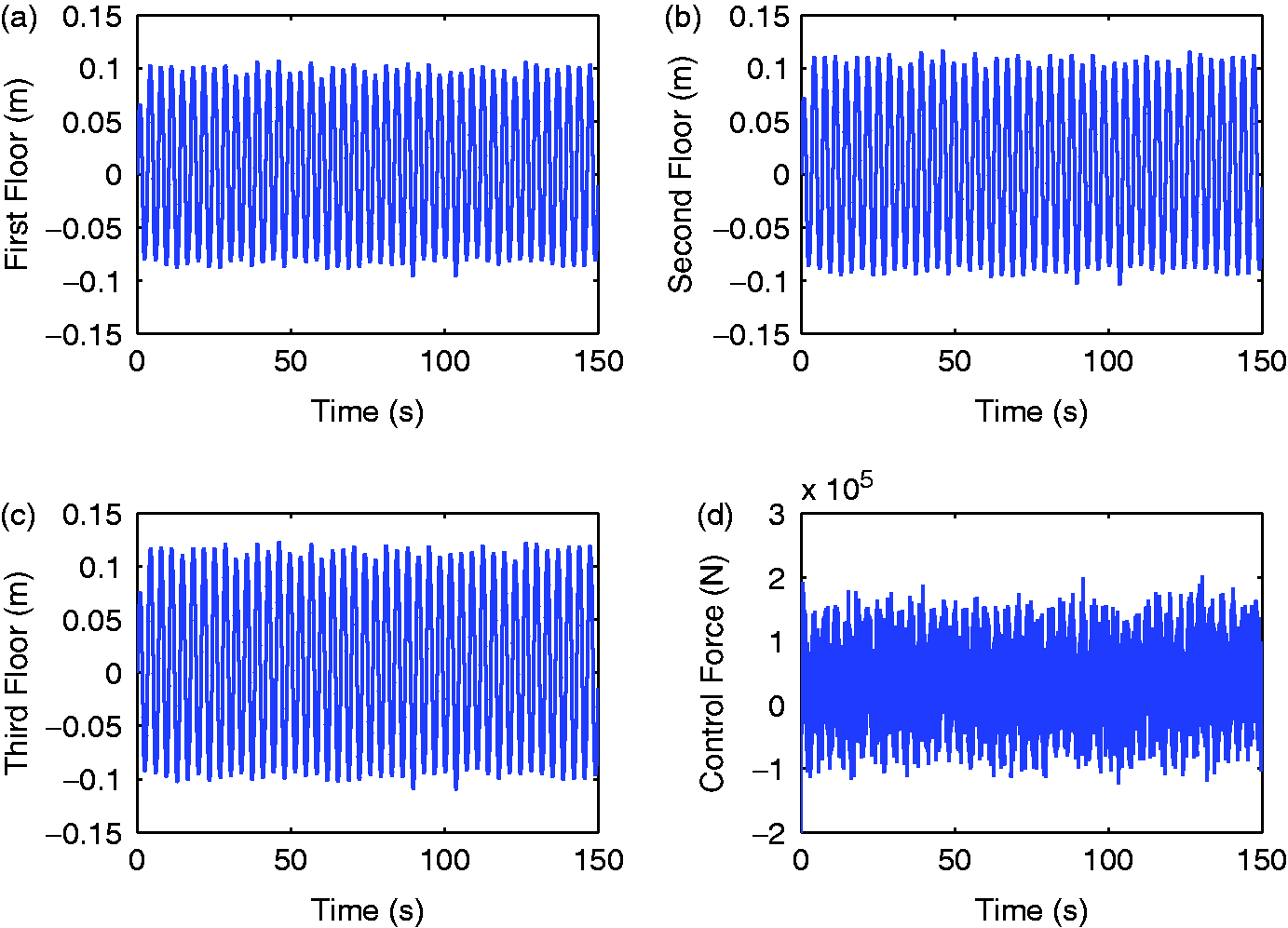
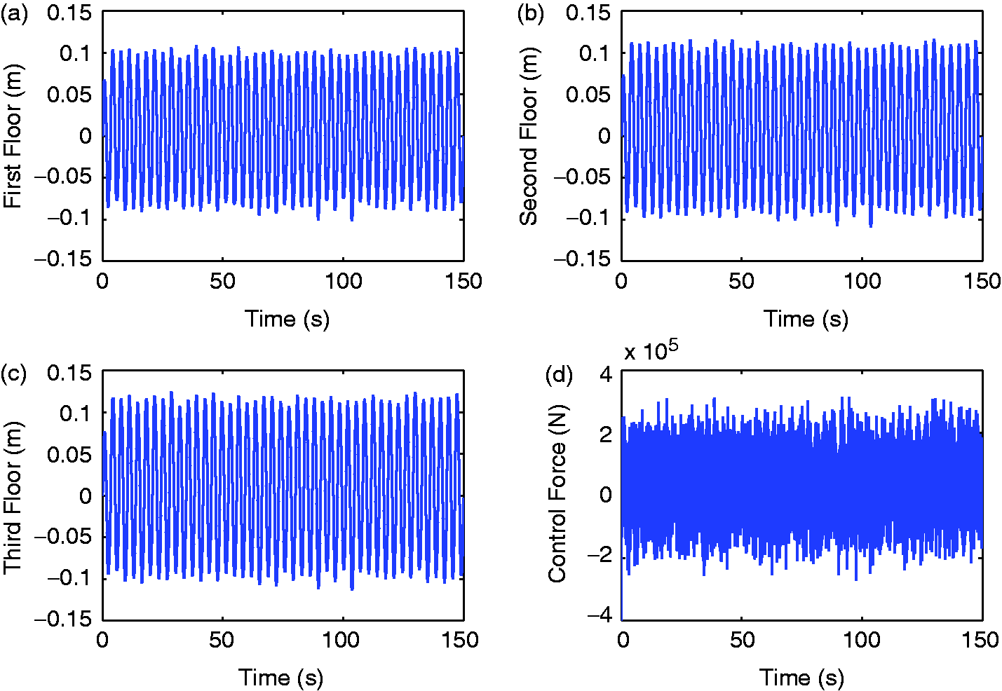
Under the obtained NFHC, the oscillation amplitudes of the first, second and third floors of the nominal system (39) are m, m and m peak to peak, respectively. The maximum control force required is about N. Depicted in Figure 2 are the responses of the first, second and third floors of the offshore platform and the required control force, respectively.
Responses of the system (39) and the control force under NFHC.
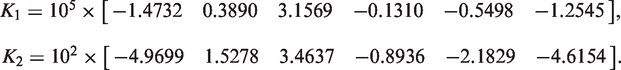
Then, we focus on studying the delayed non-fragile control. Set s and . The values of other parameters μ, γ, V, U1 and are the same as those given above. By Corollary 2, we obtain the gain matrices K1 and K2 of a delayed non-fragile controller (DNFHC) as
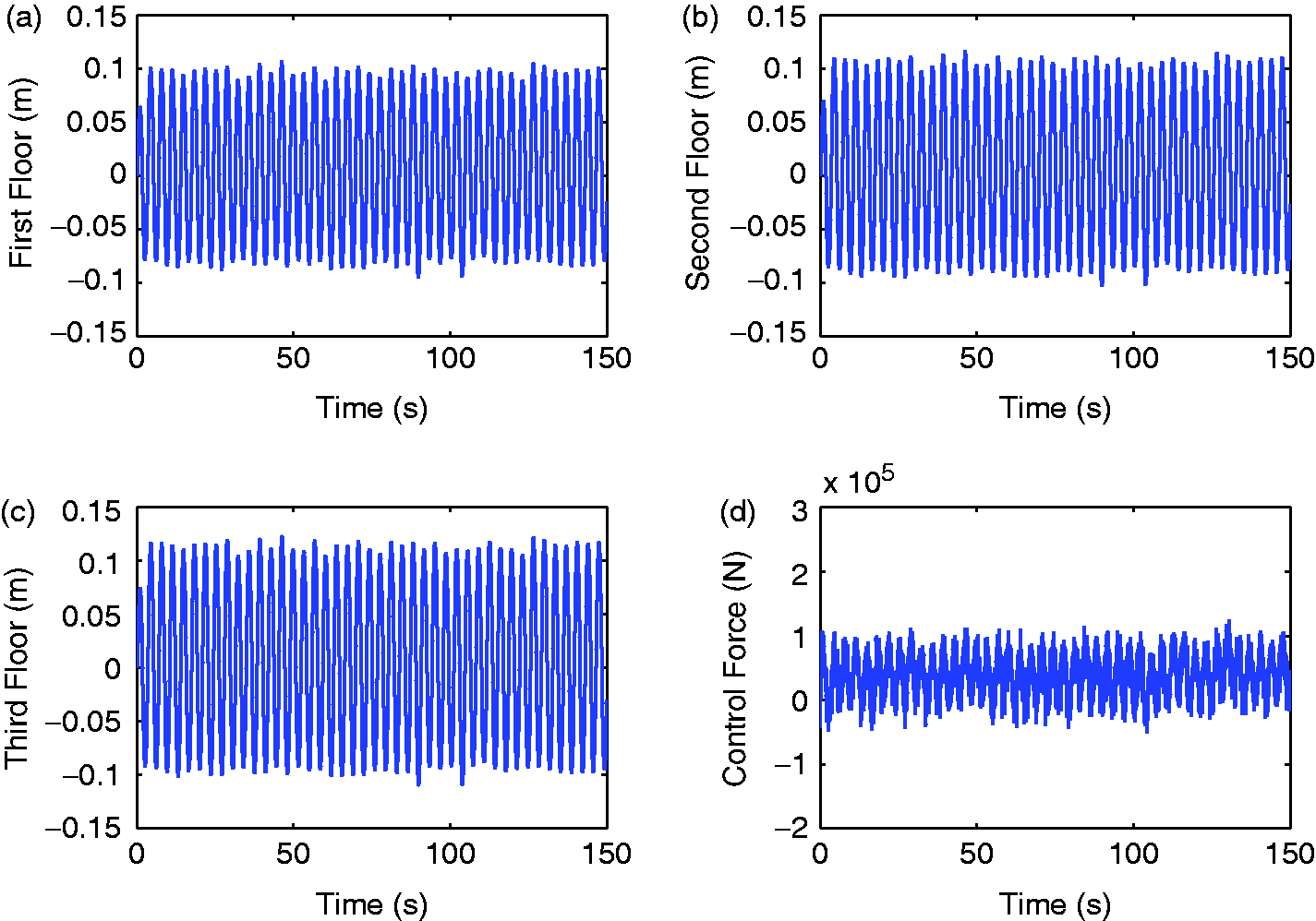
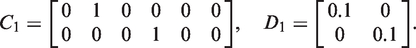
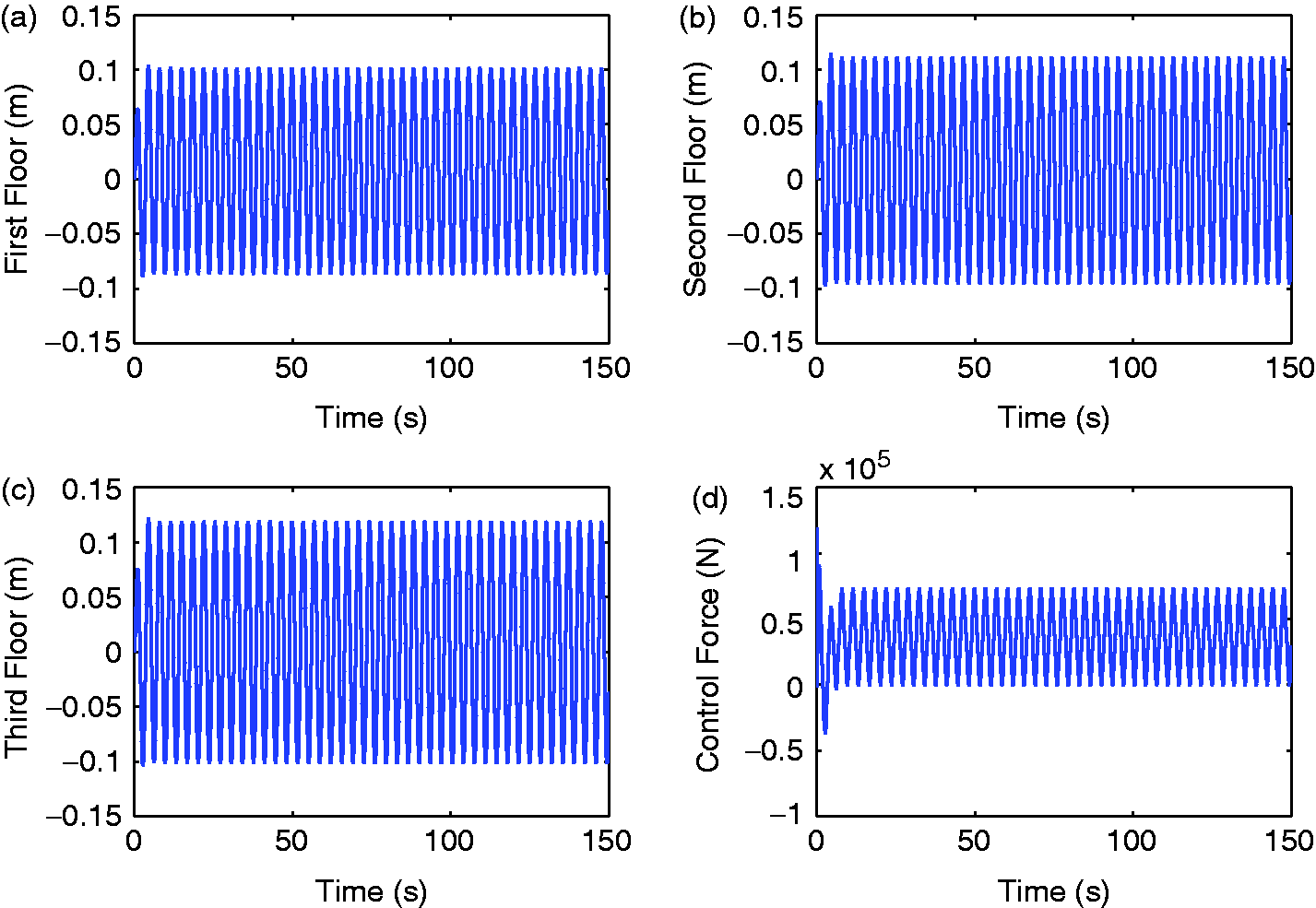
When the DNFHC is applied to control the nominal system (39), the response of the three floors and the control force are showed in Figure 3. It can be seen that the oscillation amplitudes of the first, second, third floors peak to peak are m, m and m, respectively, and the range of the control force peak to peak is about N.
Responses of the system (39) and the control force under DNFHC.
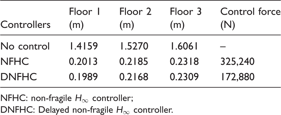
The oscillation amplitudes of the three floors and the required control force are listed in Table 1, where the oscillation amplitudes of the three floors of the system without control are presented (Zhang et al., 2013). It can be seen from Table 1 that under the NFHC and the DNFHC, the average oscillation amplitudes of the three floors of the system are reduced to 14.3% and 14.2% of that without control, respectively. The reduction of the vibration of the three floors under the two non-fragile controllers are almost at the same level. However, it is clear to see that the control force by the NFHC is 1.88 times as that by the DNFHC. This indicates that by intentionally introducing a time-delay into the control channel, the required control force can be reduced.
Maximum oscillation amplitudes of the nominal system (39) and the range of the control force under different controllers.
Controllers
Floor 1 (m)
Floor 2 (m)
Floor 3 (m)
Control force (N)
No control
1.4159
1.5270
1.6061
–
NFHC
0.2013
0.2185
0.2318
325,240
DNFHC
0.1989
0.2168
0.2309
172,880
NFHC: non-fragile controller;
DNFHC: Delayed non-fragile controller.
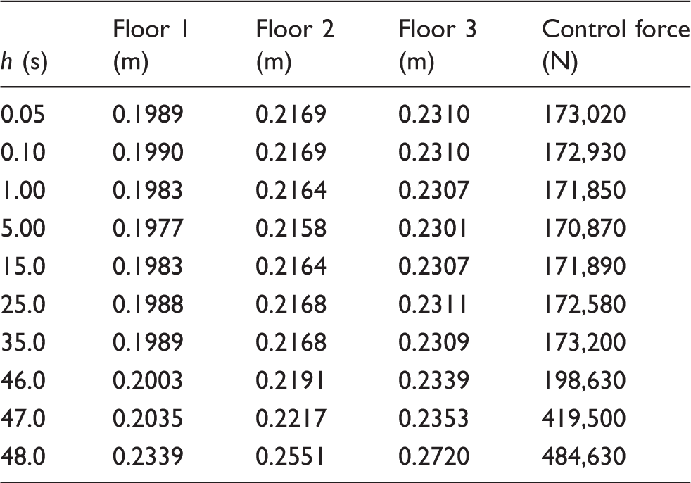
To investigate the effects of introduced time delays on the non-fragile control for the system, we apply DNFHC to control the nominal system, and let time delay h take different values. Then we calculate the peak-to-peak oscillation amplitudes of the three floors and the range of the required control force, which are listed in Table 2, from which the following conclusions may be drawn.
Under the DNFHC, as s, the average reduction of the vibration of three floors of the nominal system is the almost same as the one under the delay-free NFHC, while the required control force by the DNFHC is much smaller than the one by the NFHC, which shows that time-delays properly introduced can make a positive contribution to the non-fragile control for the offshore steel jacket platform.
Under the DNFHC, the allowable time-delay can be obtained as 46.0 s. Compared with the delayed dynamic output feedback controller (DDOFC) (Zhang et al., 2011), where the upper bound of the introduced time-delay with positive effects is less than 0.11 s, the DNFHC can provides more options of the time-delay to improve the control performance of the offshore platform.
Maximum oscillation amplitudes of the nominal system (39) and the range of the control force under the delayed non-fragile controller (DNFHC) for different values of time-delay h.
h (s)
Floor 1 (m)
Floor 2 (m)
Floor 3 (m)
Control force (N)
0.05
0.1989
0.2169
0.2310
173,020
0.10
0.1990
0.2169
0.2310
172,930
1.00
0.1983
0.2164
0.2307
171,850
5.00
0.1977
0.2158
0.2301
170,870
15.0
0.1983
0.2164
0.2307
171,890
25.0
0.1988
0.2168
0.2311
172,580
35.0
0.1989
0.2168
0.2309
173,200
46.0
0.2003
0.2191
0.2339
198,630
47.0
0.2035
0.2217
0.2353
419,500
48.0
0.2339
0.2551
0.2720
484,630
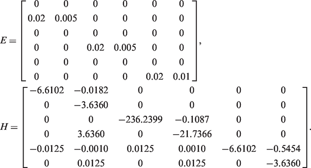
4.2. Performance of the uncertain system with delayed robust non-fragile control
Suppose that the maximum perturbation bounds , and . Then by (6), the matrices E and H in system (5) can be obtained as
Set and . The time-varying perturbation matrix F(t) in the system is given by , the perturbation parameters in the controller gain are assumed to be
Then, by Corollary 1, we design a robust non-fragile controller (RNFHC) in the form (36), where the gain matrix K1 is obtained as
Under the RNFHC, the responses of the three floors and the required control force are showed in Figure 4. It can be obtained that the peak-to-peak oscillation amplitudes of the first, second and third floors are m, m and m, respectively. The maximum control force is about N.
Responses of the system (5) and the control force under RNFHC.
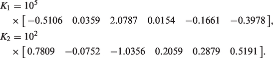
Now, let s and . Then we design a delayed robust non-fragile controller (DRNFHC) by Proposition 2, and the gain matrices K1 and K2 can be computed as
As the DRNFHC is used to control the uncertain system, the oscillation amplitudes of the first, second and third floors of the uncertain system (5) are m, m and m, respectively. The maximum control force required is N. The responses of the three floors of the system and the control force are given by Figure 5.
Responses of the system (5) and the control force under DRNFHC.
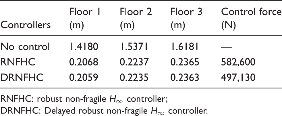
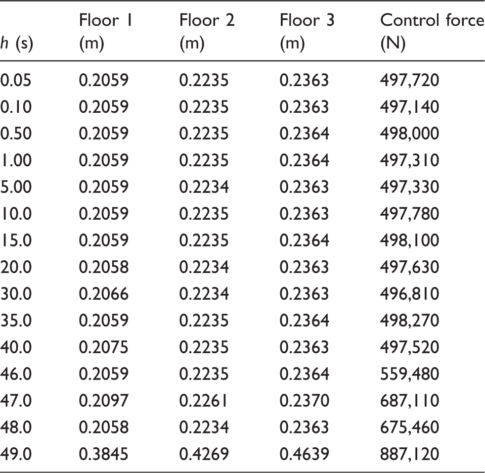
To compare two robust non-fragile control schemes, the control force and the oscillation amplitudes of the three floors of the uncertain system under no control (Zhang et al., 2013), RNFHC and DRNFHC are listed in Table 3. It can be seen that under RNFHC and DRNFHC, the average oscillation amplitudes of the three floors of the uncertain system are both reduced to about 14.5% of the value when no controller is applied. However, the control force required by RNFHC is 1.17 times as large as that by DRNFHC, which indicates that to obtain the same control performance, the control force required by DRNFHC is smaller than that by RNFHC. In fact, as demonstrated in Table 4, DRNFHC can achieve the same control performance as RNFHC, while it takes less control cost than RNFHC as time-delay s.
Maximum oscillation amplitudes of the uncertain system (5) and the range of the control force under different controllers.
Controllers
Floor 1 (m)
Floor 2 (m)
Floor 3 (m)
Control force (N)
No control
1.4180
1.5371
1.6181
—
RNFHC
0.2068
0.2237
0.2365
582,600
DRNFHC
0.2059
0.2235
0.2363
497,130
RNFHC: robust non-fragile controller;
DRNFHC: Delayed robust non-fragile controller.
Maximum oscillation amplitudes of the uncertain system (5) and the control force under the delayed robust non-fragile controller (DRNFHC) for different values of time delay h.
h (s)
Floor 1 (m)
Floor 2 (m)
Floor 3 (m)
Control force (N)
0.05
0.2059
0.2235
0.2363
497,720
0.10
0.2059
0.2235
0.2363
497,140
0.50
0.2059
0.2235
0.2364
498,000
1.00
0.2059
0.2235
0.2364
497,310
5.00
0.2059
0.2234
0.2363
497,330
10.0
0.2059
0.2235
0.2363
497,780
15.0
0.2059
0.2235
0.2364
498,100
20.0
0.2058
0.2234
0.2363
497,630
30.0
0.2066
0.2234
0.2363
496,810
35.0
0.2059
0.2235
0.2364
498,270
40.0
0.2075
0.2235
0.2363
497,520
46.0
0.2059
0.2235
0.2364
559,480
47.0
0.2097
0.2261
0.2370
687,110
48.0
0.2058
0.2234
0.2363
675,460
49.0
0.3845
0.4269
0.4639
887,120
4.3. Comparison of the delayed state feedback control scheme and the existing control schemes
Let s and . Then, by Corollary 4, a delayed state feedback controller (DSFC) in the form (44) is obtained, where
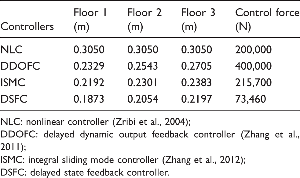
When the obtained DSFC is applied to control the system (9), the responses of the three floors of the system and the control force are presented in Figure 6. It can be computed that the oscillation amplitudes of the first, second and third floors of the system are reduced to 0.1873 m, 0.2054 m, and 0.2197 m, respectively, and the range of the control force required is about N. Table 5 lists the range of the control force and the oscillation amplitudes of the three floors of the system (9) under the different controllers: nonlinear controller (NLC) (Zribi et al., 2004), DDOFC (Zhang et al., 2011), and integral sliding mode controller (ISMC) (Zhang et al., 2012). From Table 5, one observes that:
The oscillation amplitudes of the three floors of the offshore platform under delayed sliding mode controller (DSMC) are much smaller than those under NLC, DDOFC and ISMC. Moreover, the range of the control force required by DSMC is much less than the one by NLC, DDOFC and ISMC.
It can be computed that under the obtained DSFC, the maximum allowable time delay with positive effects on the control performance of the system (9) can reach 60 s, which is much larger than the one under DDOFC.
Maximum oscillation amplitudes of the system (9) and the range of the control force with different controllers.
Responses of the system (9) and the control force under DSFC.
5. Conclusion
The delayed non-fragile control scheme for the offshore platform has been proposed. The positive effects of time delays on the non-fragile control for the system have been investigated. The simulation results have shown that by properly introducing time delay into the control channel, the control force created by the delayed non-fragile control scheme can be significantly reduced. Moreover, the obtained allowable maximum time delay with the delayed non-fragile control scheme is much larger than that with delayed dynamic output feedback control scheme.
Footnotes
Funding
This work was supported in part by the Natural Science Foundation of China (grant number 60874029), the Scientific Research Foundation for the Returned Overseas Chinese Scholars, Ministry of Education of China (grant number 2012-1707), the Natural Science Foundation of Zhejiang Province (grant number Y1110036), the Science and Technology Planning Project of Zhejiang Province (grant number 2012C21022), the Australian Research Council Discovery Project (grant number DP1096780), and the Research Advancement Awards Scheme Program (January 2010–December 2012) at Central Queensland University, Australia.
References
1.
AtayFM (2002) Delayed-feedback control of oscillations in non-linear planar systems. International Journal of Control75: 297–304.
2.
BraghinFCinquemaniSRestaF (2013) Multi-modal vibration control using amended disturbance observer compensation. Journal of Vibration and Control19: 163–182.
3.
ChatterjeeS (2008) Vibration control by recursive time-delayed acceleration feedback. Journal of Sound and Vibration317: 67–90.
4.
ChatterjeeaSDasbKChattopadhyayJ (2007) Time delay factor can be used as a key factor for preventing the outbreak of a disease—results drawn from a mathematical study of a one season eco-epidemiological model. Nonlinear Analysis: Real World Applications8: 1472–1493.
5.
ChenC-W (2011) Modeling, control and stability analysis for time-delay TLP systems using the fuzzy Lyapunov method. Neural Computing and Applications20: 527–534.
6.
ChenC-W (2013) Delay independent criterion for multiple time-delay systems and its application in building structure control systems. Journal of Vibration and Control19: 395–414.
7.
ChenC-WShenC-WChenC-Y (2010a) Stability analysis of an oceanic structure using the Lyapunov method. Engineering Computations27: 186–204.
8.
ChenC-WYehKLiuKF (2012) Applications of fuzzy control to nonlinear time-delay systems using the linear matrix inequality fuzzy Lyapunov method. Journal of Vibration and Control18: 1561–1574.
9.
ChenC-YLinJ-WLeeW-I (2010b) Fuzzy control for an oceanic structure: a case study in time-delay TLP system. Journal of Vibration and Control16: 147–160.
10.
DuHLamJSzeKY (2005) Design of non-fragile H∞ controller for active vehicle suspensions. Journal of Vibration and Control11: 225–243.
11.
GuKHanQ-LLuoACJ (2001) Discretized Lyapunov functional for systems with distributed delay and piecewise constant coefficient. International Journal of Control74: 737–744.
12.
HanQ-L (2002) New results for delay-dependent stability of linear systems with time-varying delay. International Journal of Systems Science33: 213–228.
13.
HanQ-L (2009) Improved stability criteria and controller design for linear neutral systems. Automatica45: 1948–1952.
14.
JnifeneA (2007) Active vibration control of flexible structures using delayed position feedback. Systems and Control Letters56: 215–222.
15.
KimDH (2009) Neuro-control of fixed offshore structures under earthquake. Engineering Structures31: 517–522.
16.
KorkmazS (2011) A review of active structural control: challenges for engineering informatics. Computers and Structures89: 2113–2132.
17.
LiHLiuHHiltonC (2013) Non-fragile H∞ control for half-vehicle active suspension systems with actuator uncertainties. Journal of Vibration and Control19: 560–575.
18.
LiHJHuS-LJJakubiakC (2003) H2 active vibration control for offshore platform subjected to wave forces. Journal of Sound and Vibration263: 709–724.
19.
LiJTangG-Y (2010) Fault diagnosis for networked control systems with delayed measurements and inputs. IET Control Theory and Applications4: 1047–1054.
20.
LiLSongGOuJ (2010) Nonlinear structural vibration suppression using dynamic neural network observer and adaptive fuzzy sliding mode control. Journal of Vibration and Control16: 1503–1526.
21.
LiXJiJCHansenCH (2006) The response of a Duffing-van der Pol oscillator under delayed feedback control. Journal of Sound and Vibration291: 644–655.
22.
LuoMZhuWQ (2006) Nonlinear stochastic optimal control of offshore platforms under wave forces. Journal of Sound and Vibration296: 734–745.
23.
MaccariA (2003) Vibration control for the primary resonance of the van der Pol oscillator by a time-delay state feedback. International Journal of Non-Linear Mechanics38: 123–131.
24.
MaccariA (2008) Vibration amplitude control for a van der Pol-Duffing oscillator with time delay. Journal of Sound and Vibration317: 20–29.
25.
MichielsWNiculescuS-IMoreauL (2004) Using delays and time-varying gains to improve the static output feedback stabilizability of linear systems: a comparison. IMA Journal of Mathematical Control and Information21: 393–418.
26.
PengCTianY-C (2009) Delay-dependent robust H∞ control for uncertain systems with time-varying delay. Information Sciences179: 3187–3197.
27.
RobinettRDPettersonBJFahrenholtzJC (1998) Lag-stabilized force feedback damping. Journal of Intelligent and Robotic Systems21: 277–285.
28.
SalariehHAlastyA (2008) Delayed feedback control of chaotic spinning disk via minimum entropy approach. Nonlinear Analysis: Theory, Methods and Applications69: 3273–3280.
29.
SongBSunJ-Q (2012) Sliding mode control of uncertain dynamical systems with time delay using the continuous time approximation method. Journal of Vibration and Control18: 1254–1260.
30.
TerroMJMahmoudMSAbdel-RohmanM (1999) Multi-loop feedback control of offshore steel jacket platforms. Computers & Structures70: 185–202.
31.
UdwadiaFEPhohomsiriP (2006) Active control of structures using time delayed positive feedback proportional control designs. Structural Control and Health Monitoring13: 536–552.
32.
WilsonJF (2002) Dynamics of offshore structures, Hoboken, NJ: John Wiley & Sons Inc.
33.
ZhangX-MHanQ-L (2012) Novel delay-derivative-dependent stability criteria using new bounding techniques. International Journal of Robust and Nonlinear Control. DOI: 10.1002/rnc.2829.
34.
YangXLSunZK (2010) Research on parametric resonance in a stochastic van der Pol oscillator under multiple time delayed feedback control. International Journal of Non-Linear Mechanics45: 621–627.
35.
ZhangB-LHanQ-LZhangX-M (2012) Integral sliding mode control for offshore steel jacket platforms. Journal of Sound and Vibration331: 3271–3285.
36.
ZhangB-LMaLHanQ-L (2013) Sliding mode H∞ control for offshore steel jacket platforms subject to nonlinear self-excited wave force and external disturbance. Nonlinear Analysis: Real World Applications14: 163–178.
37.
ZhangX-MHanQ-LHanD-S (2011) Effects of small time-delays on dynamic output feedback control of offshore steel jacket structures. Journal of Sound and Vibration330: 3883–3900.
38.
ZhangX-MWuMSheJ-H (2005) Delay-dependent stabilization of linear systems with time-varying state and input delays. Automatica41: 1405–1412.
39.
ZribiMAlmutairiNAbdel-RohmanM (2004) Nonlinear and robust control schemes for offshore steel jacket platform. Nonlinear Dynamics35: 61–80.