






Abstract
Smart structure vibration reduction based on adaptive active vibration control has become a hot research spot in recent years. A filtered-U least mean square algorithm based on an infinite impulse response filter structure is used to solve the interference of controller output to reference signal. The filtered-U least mean square algorithm is very suitable for the nonlinear vibration control of the flexible structure. This study focuses on the analysis and implementation of an adaptive active vibration control system for smart structure with a surface-bonded piezoelectric actuator. The piezoelectric actuator contained in the secondary path has nonlinear hysteresis property. The nonlinear hysteresis property will cause a nonlinear relationship between the structural vibration response and the control voltage, which deteriorates the robustness and control effect of the adaptive control. This study designs an improved version of the filtered-U least mean square algorithm with online hysteresis identification and compensation (filtered-U least mean square–online hysteresis identification and compensation) based on a discrete Prandtl–Ishlinskii model. The Prandtl–Ishlinskii model parameters of the nonlinear hysteresis property are identified online based on the least mean square algorithm. Based on the identified Prandtl–Ishlinskii model parameters, an inverse hysteresis compensator is established for feedforward compensation in the secondary path. Simulation results show that the proposed method can dynamically compensate the hysteresis nonlinearity of the secondary path, linearizing the nonlinear hysteresis. The vibration reduction effect of the proposed method is obviously better than that of other competing methods. A piezoelectric smart cantilever plate with PZT (or lead zirconate titanate, Pb (Zr, Ti)) actuators and sensors is designed to demonstrate the validity and efficiency of the proposed method by experiments. Experiment results demonstrate that the adverse effect of nonlinear hysteresis is eliminated well after feedforward hysteresis compensation is introduced; the unexpected frequency vibration caused by the hysteresis property is suppressed. The proposed methodology possesses an important advantage in application of the adaptive active vibration control of the piezoelectric smart structure.
Keywords
1. Introduction
In the past several years, adaptive active vibration control (AAVC) methodology is widely implemented in structure vibration control applications because of its simplicity and effectiveness and self-adjustment ability to adapt to varying dynamics of the structure. Filtered-X least mean square (FXLMS) algorithm based on a finite impulse response (FIR) filter structure is the most common in the AAVC (Gupta, et al. 2006; Pu et al. 2019; Zheng et al. 2019). However, in practical applications, it is inevitable that the reference signal is interfered by the control signal, and the interference may change the secondary path dynamics characteristics during the operation. Infinite impulse response (IIR) filter which has its own zero-pole structure can be used to overcome the interference problem. Eriksson and Allie (1989) proposed the filtered-U least mean square (FULMS) algorithm based on an IIR filter structure firstly. Zhu et al. (2011) analyzed and applied the multi-input multi-output FULMS algorithm for active vibration suppression of a cantilever smart beam (Zhu et al., 2011). Huang et al. (2013, 2014) proposed an improved FULMS vibration control algorithm to solve the vibration reference signal extraction problem. Boz et al. (2011) combined IIR filtering-based FULMS controller with an online secondary path modeling (OSPM) algorithm to suppress the vibration of a plate-like structure. Xie et al. (2016, 2017) proposed an adaptive feedforward combined vibration control system with variable step size (VSS) FULMS to suppress the vibration of thin-wall structures.
Piezoelectric materials are often used as actuators and sensors in smart structures because of their good piezoelectric and electromechanical coupling properties (Tavakolpour et al. 2010). The piezoelectric actuator making use of the inverse piezoelectric effect of the piezoelectric material has been widely used in the AAVC (Boz et al. 2011, Choi et al. 2013; Didace et al. 2018; Zhang et al. 2013). When voltage or current is input, the piezoelectric material will deform and realize mechanical movement. The piezoelectric actuator can ensure a nanometer resolution motion and has incomparable advantages over the traditional actuator. However, there is a complex nonlinear relationship between the input control voltage and the output force of the piezoelectric actuator, leading to a nonlinear hysteresis between the control voltage and structural vibration when used in the AAVC system. The hysteresis property may induce many destructive effects to the AAVC system, reduce its stability, and even lead to the failure of the control system. Therefore, the research of hysteresis compensation has important theoretical and practical significances to improve the stability and control effect of the AAVC system.
The mathematical model of nonlinear hysteresis can be divided into two types: physical models and phenomenal models. The physical model focuses on the physical causes of nonlinear hysteresis, whereas the phenomenon models are based on the input-output relationship of the hysteresis system, striving to be consistent with the actual physical system. Classical phenomenal hysteresis models include the Preisach model (Shao et al. 2016), Prandtl–Ishlinskii (PI) model (Dong and Tan, 2009), and Maxwell model (Juhasz et al., 2011). However, these above models mainly only focused on the hysteresis characteristics themselves, with little attention to the coupling characteristics between the nonlinear hysteresis and the active vibration control system. To reduce the negative effect of nonlinear hysteresis on the active control system, an effective method is to construct a feedforward compensator based on the inverse hysteresis model parameters. Yi et al. (2019) proposed an offline identification of magnetostrictive-induced hysteresis based on the PI model; inverse hysteresis was then applied to compensate the hysteresis and to alleviate micro-vibration. However, it was observed that hysteresis behavior of the piezoelectric actuator depends on different environmental parameters, that is, object mass, voltage excitation, frequency, and temperature. The change of vibration environment will lead to the change of nonlinear hysteresis characteristics of the secondary path, including the direction and shape of the hysteresis ring. The hysteresis model parameters obtained by an offline identification method do not exactly match the dynamic hysteresis characteristics of the piezoelectric actuator, and hysteresis compensation based on inaccurate hysteresis model parameters will lead a significant error between the desired control output and actual output. However, few researches worked on online identification and dynamic linearization compensation of hysteresis, which has become a key issue to solve in the application of the AAVC of the smart structure.
In this study, a smart piezoelectric structure with a hysteresis property is presented to study adaptive vibration control strategy with online hysteresis identification and compensation (ONHIC). The rest of this study is organized as follows. In Section 2, the nonlinear hysteresis property of the piezoelectric actuator and its adverse effect on the AAVC system are analyzed. Section 3 describes the FULMS algorithm based on the IIR transverse filter structure. The proposed control algorithm with online hysteresis identification and compensation module (FULMS-ONHIC) is designed in Section 4. The simulation and experimental results of the proposed active control algorithm comparing with the competing algorithms based on OSPM and offline hysteresis identification are present in Section 5. Finally, some conclusions are given in Section 6.
2. Hysteresis property of piezoelectric actuator
Piezoelectric actuators have been widely used in the AAVC system because of their extraordinary properties and performance, such as small size, high energy density, high resolution, and quick frequency response. However, the adverse effect of hysteretic behavior of the piezoelectric actuator on the AAVC control system may cause the amplitude and phase distortion of the control voltage. As a result, the active control effect in the closed loop system is weakened or even diverged.
Here, as the input control voltage of a PZT actuator, a harmonic signal with 40.2 Hz is applied to excite the smart structure vibration so that its hysteresis property can be tested. Figure 1 shows the hysteretic relationship between the input control voltage and the structural vibration response at the same time. X- and Y-axes represent the input control voltage and structural vibration response, respectively, which are normalized to (−1, 1) by dividing all the data by the maximum. The size and direction of the nonlinear hysteretic loop are related to the frequency and amplitude of the control voltage. The nonlinear hysteresis indicates that the calculated input control voltage cannot be performed correctly by the PZT actuator. The hysteresis property leads to a nonlinear relationship between the structural vibration response and control voltage. The vibration response at unexpected frequencies would be excited, which may cause the structure to resonate at these frequencies. It can be seen that the hysteresis will worsen the robustness of the control algorithm and should be compensated to eliminate its adverse effects on the AAVC system. Nonlinear hysteresis property of the piezoelectric actuator.
3. FULMS algorithm based on IIR transverse filter structure
A filtered-U least mean square algorithm combined with an IIR filter structure has been widely implemented in active noise applications. The FULMS algorithm is also an alternative method for the active vibration control of flexible smart structures because of its adaptive ability to dynamic variations of structures.
The transfer function of the IIR filter structure used in the FULMS algorithm can be expressed as


Similar to the FXLMS algorithm, the FULMS algorithm requires the reference signal and control signal filtered by the secondary path as feedforward input.


The coefficients of the control filter are updated through the FULMS algorithm




4. FULMS–ONHIC algorithm
In general, hysteresis model parameters of a piezoelectric actuator can be obtained by off-line identification. However, the time-varying vibration environment causes variation of hysteresis model parameters of an actuator, which is unavoidable in practical AAVC applications. The variable hysteresis parameters increase the difficulty of the control output being executed accurately and lead to nonlinear modeling error of the secondary path, which is very unfavorable to the stability of the feedforward active control system. Therefore, it is very important to identify the nonlinear hysteresis parameters by online strategies and to design dynamic hysteresis compensation strategy to linearize the secondary vibration path containing the piezoelectric actuator.
The proposed control scheme based on the FULMS algorithm with ONHIC module (FULMS–ONHIC) is shown in Figure 2. It consists of three key modules: adaptive active controller module based on the IIR filter, OSPM module, and ONHIC module. The hysteresis identification filter has a structure with several backlash operators in series based on the PI model. It is constructed by replacing delay operators with backlash operators based on the FIR filter. The proposed adaptive hysteresis identification filter has a same structure as FIR filter with a transverse filter structure, so it has the advantages of the FIR filter and is easy to implement. On the other hand, as a nonlinear filter, it has a good performance on approximating nonlinear hysteresis. Schematic diagram of the proposed filtered-U least mean square–online hysteresis identification and compensation algorithm.
Here, we emphasize that the study focuses on the influence of nonlinear hysteresis of the piezoelectric actuator on the AAVC system. Since the ONHIC method of the piezoelectric sensor is the same as the piezoelectric actuator, for simplicity and clarity, the hysteresis of the piezoelectric sensor is neglected to reduce the complexity of the proposed AAVC system. In addition, considering that the sensing scheme may be various in practical applications, such as strain gauge, acceleration sensor, visual sensor, laser tracker, and so on, the proposed FULMS–ONHIC algorithm of this study can also be suitable for AAVC systems based on those sensing schemes without the hysteresis effect.
4.1. ONHIC module
Because of the nonlinear hysteresis property of the piezoelectric actuator, the structure vibration response excited by the piezoelectric actuator is determined not only by the current input voltage, but also by the previous input voltage history. Because of the simple structure, few parameters, and analytical inverse model, the PI model is widely used in the research of hysteresis nonlinear modeling and compensation. Considering the superposition of finite backlash operators can make the hysteresis loop achieve high precision, and the hysteresis inverse model of the PI model is easy to obtain, we use the PI model to describe the hysteresis property in this study.
4.1.1. Adaptive hysteresis identification
The transfer characteristics of the backlash operator and schematic diagram of the PI model are shown in Figure 3, respectively. The backlash operator can describe the relationship between output and input. In the proposed online hysteresis identification module, Schematic diagram of the Prandtl–Ishlinskii model (a) transfer characteristic of the backlash operator; (b) weighted sum of backlash operators.

Because of the continuity of the basic backlash operator, any complex hysteresis property can be modeled by a finite number of basic operators by weighted superposition. The property of the backlash operator is mainly determined by threshold width and input signal amplitude. The discrete form of the ith backlash operator

The initial value

The output of the PI model


It should be mentioned that the threshold width of each backlash operator can be set to same, or it can be optimized by a certain optimization algorithm to improve the performance of identification. Here, the same threshold width of backlash operators will be selected, avoiding the trouble caused by the choice of operators of different widths, and making it easy for the implementation of hardware.
4.1.2. Dynamic inverse hysteresis model
The advantage of the PI model compared with the classical Preisach model is that its analytic inverse model which is also a PI model. The threshold vector and weight vector of the PI inverse model can be calculated through the relationship between the PI model and its inverse model. The PI hysteresis inverse model is embedded in the secondary path. Before driving the piezoelectric actuator, the control signal is feedforward compensated by the hysteresis inverse model to realize the linearization of the secondary path.
The output of the inverse model is shown as


5. Simulation and experimental results and analysis
5.1. Simulation results and analysis
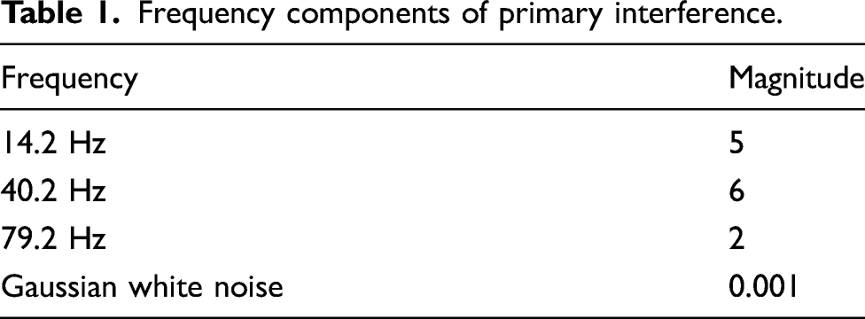
Frequency components of primary interference.
Step size parameters of control algorithms.
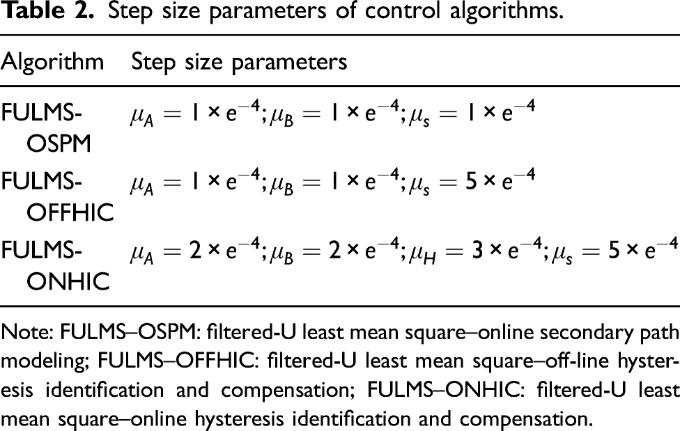
Note: FULMS–OSPM: filtered-U least mean square–online secondary path modeling; FULMS–OFFHIC: filtered-U least mean square–off-line hysteresis identification and compensation; FULMS–ONHIC: filtered-U least mean square–online hysteresis identification and compensation.
To verify the adaptive performance of the proposed ONHIC algorithm to deal with dynamic hysteresis caused by the secondary path change, a sudden change is introduced to the secondary path at 10 s. The secondary path containing the PZT actuator changes, and the parameters of the PI hysteresis model change accordingly. The parameters before and after the perturbation are

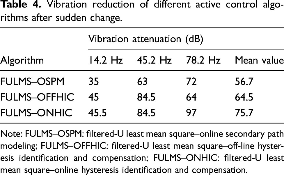
The time and frequency curves of the vibration response are shown in Figure 4. The vibration reductions of different active control algorithms are compared in Tables 3 and 4. It should be noted that, because of the OSPM module embedded into the control system, the auxiliary random noise is injected into the residual vibration response, resulting in upward shifts of magnitude to some extent. Simulation results (a) time history curves; (b) power spectrum curves before sudden change; (c) power spectrum curves after sudden change. Vibration reduction of different active control algorithms before sudden change. Note: dB = 10log(P/Pr), where P-the actual power value and Pr-the reference power value which is set to 1. FULMS–OSPM: filtered-U least mean square–online hysteresis identification and compensation; FULMS–OFFHIC: filtered-U least mean square–off-line hysteresis identification and compensation; FULMS–ONHIC: filtered-U least mean square–online hysteresis identification and compensation. Vibration reduction of different active control algorithms after sudden change. Note: FULMS–OSPM: filtered-U least mean square–online secondary path modeling; FULMS–OFFHIC: filtered-U least mean square–off-line hysteresis identification and compensation; FULMS–ONHIC: filtered-U least mean square–online hysteresis identification and compensation.
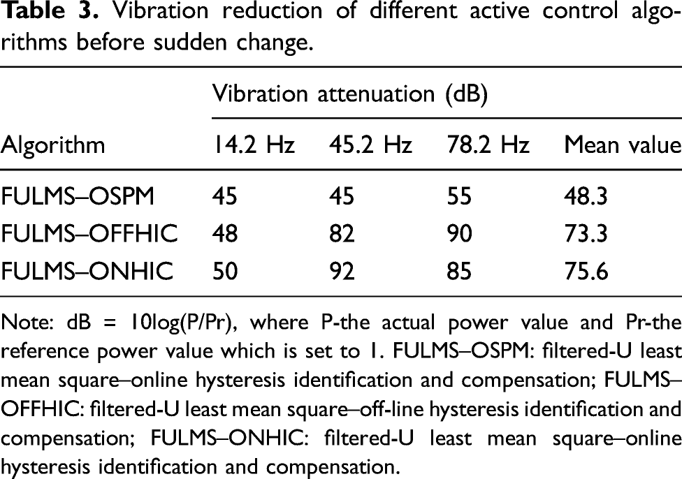
Before the sudden change, based on the FIR filter structure, the OSPM cannot realize the identification of the nonlinear hysteresis model, and there is no linearization process of nonlinear hysteresis. The vibration control effect of the FULMS–OSPM algorithm is poor, and the mean vibration reduction at the interested frequencies is only 48.3 dB. Unexpectedly, the vibration responses at 3 Hz, 37.8 Hz, 76.4 Hz, and 81.6 Hz are excited because of the hysteresis property, and thus the vibration control effect has been seriously weakened. Based on the nonlinear hysteresis model parameters obtained by off-line identification, the FULMS–OFFHIC algorithm with an inverse hysteresis model acquires a mean vibration reduction with 73.3 dB at the interested frequencies before sudden change.
Due to online identification and dynamic inverse compensation of nonlinear hysteresis embedded in the active control algorithm, the proposed FULMS–ONHIC algorithm also achieves a good control effect, and the mean vibration reduction at the interested frequencies is 75.6 dB. In Figure 4(b), it can be seen that the vibration responses at unexpected frequencies are effectively suppressed at the same time by using the FULMS–OFFHIC and the proposed FULMS–ONHIC algorithm.
A sudden change of the secondary path occurs at 10 s. After the sudden change, the structural vibration response is decreasing gradually again, and actual parameters of nonlinear hysteresis are far from those obtained by off-line identification. The exact feedforward inverse compensation model cannot be obtained by the FULMS–OFFHIC method based on inexact parameters of the hysteresis model. The linearization of the hysteresis property is seriously affected, which worsens the vibration reduction of the structure. The mean vibration reduction at interested frequencies is 64.5 dB, and the vibration amplification occurs at 60 Hz and 72 Hz. This indicates that the vibration response at unexpected frequencies has not been effectively suppressed.
In the proposed method, the hysteresis parameters are online identified by (11), and dynamic compensation is realized by (14). The proposed FULMS–ONHIC algorithm maintains a good control effect after a sudden change, with an average vibration reduction of 75.7 dB at interested frequencies. The vibration response at unexpected frequencies is effectively suppressed. It can be found that the proposed algorithm can be used to linearize varying nonlinear hysteresis before and after the sudden change.
The actual nonlinear hysteresis of the secondary path and the estimated inverse hysteresis model of the feedforward hysteresis compensator are plotted in Figure 5, in which the input and output are normalized waveforms. Figure 5(a) shows the dynamic estimated inverse hysteresis based on the hysteresis parameters by online identification before the sudden change. The estimated inverse hysteresis is symmetric with the actual hysteresis model. And thus, the proposed method realizes the dynamic compensation for nonlinear hysteresis of the secondary path. By hysteresis compensation, the actual output of the piezoelectric actuator can track the expected input control voltage linearly. Figure 5(b) shows estimated inverse hysteresis and the dynamic compensation results after the sudden change. The nonlinear hysteresis is effectively linearized, indicating that the proposed FULMS–ONHIC method can adapt to dynamic hysteresis variation. Actual hysteresis and its inverse model: (a) before sudden change; (b) after sudden change.
5.2. Experimental results and analysis
To investigate the actual control effect of the active vibration control method based on the proposed nonlinear dynamic hysteresis compensation method, experimental verification is necessary. In this section, we aim to evaluate the effectiveness of the proposed ONHIC method on the piezoelectric smart structure.
A piezoelectric smart cantilever plate with piezoelectric actuators and sensors is designed for experimental verification. The proposed smart structure is a cantilever plate consisting of the epoxy resin material with distributed embedded PZT sensors and actuators. The smart plate has good strength and flexibility during the operation. The dimension of the smart plate is 760 × 100 × 2.5 mm. The dimension of the piezoelectric patches used as actuators in our experiments is 40 × 40 × 1 mm, and those as sensors are 10 × 10 × 1 mm. Two piezoelectric patches which are in parallel connection and bonded on the top and bottom at the same location from the left side of the smart plate are classified into one group as one actuator. Since the PZT actuators used in our experiments are strain-type actuators, high strain region of every order vibration mode should be identified to place the PZT actuators. The configuration of the proposed smart cantilever plate is shown in Figure 6. Configuration of a smart cantilever plate.
Modal frequencies of the smart cantilever plate.
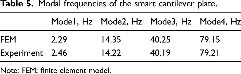
Note: FEM; finite element model.
The schematic diagram of the implemented real-time AAVC system on the smart cantilever plate based on an NI CompactRIO controller is shown in Figure 7. View of the experimental setup.
AAVC for single-mode vibration The primary vibration signal is set as a sine signal with a frequency of 79.2 Hz to excite the fourth bending vibration mode. The AAVC experimental results are shown in Figure 8. With or without nonlinear hysteresis inverse compensation, AAVC algorithms can converge rapidly in both cases by adjusting the step size parameters. With feedforward hysteresis back compensation, the vibration attenuates 90% only within 15 s, whereas without feedforward hysteresis back compensation, the vibration attenuates 80% within 17 s. From Figure 8(c), the structural vibration reduction is about 20 dB at 79.2 Hz without hysteresis compensation. However, the vibration responses are excited at 76 Hz and 82.5 Hz. The structural vibration reduction reaches about 52 dB at 79.2 Hz with hysteresis compensation. The vibration responses at the unexpected frequencies caused by hysteretic nonlinearity of the piezoelectric actuator are well suppressed. Compared to the AAVC without hysteresis compensation, the vibration responses are suppressed about 16 dB at 76 Hz and 22 dB at 82.5 Hz.

Experimental results for Case 1: (a) vibration responses without hysteresis reverse compensation; (b) vibration responses with hysteresis reverse compensation; (c) power spectrum without hysteresis reverse compensation; (d) power spectrum with hysteresis reverse compensation.
AAVC for multimode vibration The primary vibration signal is set as a multifrequency signal with frequency of 40.2 Hz and 79.2 Hz to excite the third and fourth bending vibration mode. The AAVC experimental results are shown in Figure 9. The AAVC with ONHIC for multimode control exhibits superior performance similar to that for the single-mode control. The vibration responses at the unexpected frequencies are well suppressed. Compared to the AAVC without hysteresis compensation, the structural vibration reductions are increased by 12 dB at 40.2 Hz and 32 dB at 79.2 Hz. Multimode control with the proposed dynamic feedforward compensation method improves the robustness of the adaptive control very well. Dynamic linearization of nonlinear hysteresis of the secondary path makes the AAVC system with the PZT actuator easier to control and helps to improve the control effect.

Experimental results for Case 2: (a) vibration responses without hysteresis reverse compensation; (b) vibration responses with hysteresis reverse compensation; (c) power spectrum without hysteresis reverse compensation; (d) power spectrum with hysteresis reverse compensation.
6. Conclusions
This study proposes a FULMS–ONHIC algorithm with ONHIC module based on the discrete PI model. The nonlinear hysteresis model parameters are identified online based on the LMS algorithm, and the inverse hysteresis compensator is established for feedforward compensation in the secondary path containing piezoelectric actuators. Simulation results show that the vibration reduction of the proposed method is obviously better than that of other competing methods. The nonlinear hysteresis can be linearized through the dynamic feedforward compensation which is designed based on the hysteresis model parameters by online identification. The AAVC experiments on a piezoelectric smart cantilever plate with PZT actuators are presented to demonstrate the validity and efficiency of our proposed method. Experiment results in the AAVC for single-mode vibration demonstrate that the vibration responses at the unexpected frequencies are suppressed about 16 dB at 76 Hz and 22 dB at 82.5 Hz, compared to the AAVC in the absence of hysteresis compensation. In the AAVC for multimode vibration, the structural vibration reductions are increased by 12 dB at 40.2 Hz and 32 dB at 79.2 Hz, compared to the AAVC in the absence of hysteresis compensation.
Footnotes
Declaration of conflicting interests
The author(s) declared no potential conflicts of interest with respect to the research, authorship, and/or publication of this article.
Funding
The author(s) disclosed receipt of the following financial support for the research, authorship, and/or publication of this article: This research is supported by National Natural Science Foundation of China (Grant no. 51605127) and the Fundamental Research Funds for the Central Universities (Grant nos. JZ2019HGTB0075, JZ2019HGTB0055, PA2020GDSK0093, and PA2020GDGP0052).
