
Abstract
Achieving efficient noise isolation for small-to-medium-sized noise sources through thin, lightweight, and compact structures is an effective strategy for controlling electromechanical product noise. To simultaneously address the poor sound-leakage resistance of conventional reflection-type enclosures and the weak low-frequency isolation of thin porous materials, this paper proposes a curved acoustic metamaterial enclosure composed of thin sound-absorbing metamaterials and thin porous materials. The thin sound-absorbing metamaterials are based on an in-plane space-coiling design concept that shifts the thickness-dimensional space required by the sound-absorbing structure into a planar thin layer, effectively reducing the enclosure wall thickness. Furthermore, a parallel arrangement of multiple metamaterial modules with differentiated operating frequency bands effectively broadens the noise reduction bandwidth. Since the proposed acoustic metamaterial enclosure is primarily composed of sound-absorbing structures, it can effectively dissipate sound energy, thus mitigating the sound-leakage problem inherent to conventional reflection-type enclosures. The designed acoustic metamaterial enclosure has a height of 410 mm, an inner diameter of approximately 337 mm and a wall thickness of 23 mm. Experimental results from laboratory tests in a reverberation room demonstrate that the acoustic metamaterial enclosure exhibits favorable noise reduction performance in the 200–5000 Hz range. Under comparable external installation space constraints, the acoustic metamaterial enclosure achieves a 6.1 dB improvement in noise reduction performance compared with the conventional reflection-type leather enclosure, simultaneously achieving a low profile and high-efficiency noise reduction. Additionally, it benefits from structural simplicity, adaptability to curved surfaces, and high space efficiency, showing considerable promise for noise control in space-constrained electromechanical equipment.
Keywords
1. Introduction
Vibration and noise widely exist in various mechanical and electromechanical products, which not only degrade the service performance of the equipment but also seriously affect the physiological and psychological health of relevant personnel (Alves et al., 2020). In engineering practice, controlling noise through isolation and absorption along its transmission path is a common strategy (Cheng et al., 2022; Li et al., 2024b; Sal-Anglada et al., 2024). For small-to-medium-sized noise sources, the use of form-fitting acoustic encapsulation (e.g., enclosures) constitutes a typical and effective propagation path control approach. Conventional enclosures are mostly fabricated from high surface mass density reflective materials (Kosała, 2022; Mikulski, 2020). Constrained by the mass law, their application in the lightweight and space-constrained scenarios is significantly limited (Ma et al., 2021), and they are also highly susceptible to sound leakage caused by structural gaps owing to the lack of sound energy dissipation mechanisms. While filling the enclosure with porous materials can alleviate leakage issues, the low-frequency absorption of thin porous materials is severely compromised under strict thickness constraints. Therefore, for small-to-medium-sized noise sources, how to synergistically address the two critical challenges of the sound leakage susceptibility of conventional reflective enclosures and the inadequate low-frequency noise reduction performance of thin porous materials under limited space constraints remains a prominent technical challenge.
Using sound-absorbing materials or structures to contribute to sound insulation is a widely adopted noise-attenuation strategy and has been extensively applied to the acoustic control of enclosed or semi-enclosed spaces (Li et al., 2024a; Sagartzazu et al., 2008; Wang et al., 2025b). This “sound insulation via absorption” approach can to some extent dissipate sound energy and effectively alleviate the leakage problem caused by gaps. In recent years, the rapid development of sound-absorbing acoustic metamaterials has provided an effective solution for designing low-frequency absorbers with subwavelength thickness (Chaplain et al., 2025; Gao et al., 2022; Yang and Sheng, 2017; Zhang et al., 2020). Common basic structural forms of sound-absorbing acoustic metamaterials include Helmholtz resonators (Khodabakhsh et al., 2025; Ryoo and Jeon, 2022; Wang et al., 2025c), membrane/plate structures (Aurégan, 2018; Liu et al., 2019b; Mei et al., 2012; Wang et al., 2025a), Fabry-Pérot cavities (Han et al., 2020; Liu et al., 2023; Yang et al., 2017), slit-type absorbers (Almeida et al., 2023; Liu et al., 2021; Zhu et al., 2021), as well as combinations or derivatives of these basic structures (Liu et al., 2025b; Ma et al., 2022, 2023a; Wang et al., 2024, 2025d; Yeang and Halim, 2024). Among them, although membrane/plate structures exhibit good sound absorption and insulation performance at resonant and anti-resonant frequencies respectively, they suffer from durability issues such as membrane aging and mass detachment. Fabry-Pérot cavities can form a fundamental frequency absorption peak at 1/4 of the target acoustic wavelength, but low-frequency sound absorption requires a large cavity depth, and the bandwidth of the unit cell structure is limited. Slit-type absorbers demand high processing precision and are prone to slit clogging. In contrast, Helmholtz resonators have attracted extensive research interest owing to their structural simplicity, and high absorption efficiency. However, the sound absorption frequency band of a single Helmholtz resonator is usually narrow, making it difficult to achieve broadband noise reduction. To address this issue, researchers mainly adopt two types of methods to broaden its operating frequency band. One is to combine multiple units with different structural parameters in parallel, including weak coupling and strong coupling between the units (Boulvert et al., 2022; Huang et al., 2020; Jiménez et al., 2017; Peng et al., 2018; Wang et al., 2026). The other is to modify the structure of the basic unit so that it can generate additional sound absorption peaks at higher frequencies while retaining the original sound absorption peak, that is, utilizing the multi-order resonance sound absorption mechanism (Liu et al., 2019a, 2024a; Sun et al., 2025).
In the design of sound-absorbing acoustic metamaterials, apart from achieving low-frequency broadband sound absorption, another core challenge is to significantly reduce the structural thickness while ensuring sound absorption performance. If a traditional linear structure is adopted, its thickness will be significantly larger, especially for low-frequency noise absorption. An effective solution is to reconstruct the space in the thickness direction through the longitudinal folding or transverse coiling of the cavity. This method can compress the physical thickness of the structure in the longitudinal direction without shortening the actual propagation path of sound waves, thereby achieving a substantial reduction in thickness (Cai et al., 2014; Guo et al., 2022; Li and Assouar, 2016; Pavan and Singh, 2022, 2024; Ramachandran and Rajagopal, 2025). Furthermore, introducing the parallel coupling design on the basis of the folded or coiled cavity enables simultaneous fulfillment of the requirements for the ultra-thin structural property and low-frequency broadband sound absorption (Almeida et al., 2021; Cao et al., 2025; De Sousa et al., 2021; Ding et al., 2025; Donda et al., 2019; Ma et al., 2023b; Zeng et al., 2024).
Leveraging the advantages of sound-absorbing acoustic metamaterials in ultra-thin thickness and low-frequency broadband sound absorption, their application in duct noise reduction and the design of enclosures for small-to-medium-sized noise sources has become an important research direction for achieving efficient noise control. Both ducts and enclosures share the structural commonality of circumferentially wrapping fluids or equipment. The simplest implementation method is to splice the designed sound-absorbing acoustic metamaterial modules into a rectangular shape. For example, Liu et al. (2024b) designed a rectangular ventilation and noise reduction duct with a frequency coverage of 200–1400 Hz by assembling in-plane coiled Helmholtz resonator units. Zhang et al. (2025) designed a metasurface panel covering the frequency band of 307–706 Hz by taking the labyrinthine metasurfaces with embedded apertures and bending channels as the basic units, and further fabricated a rectangular box-shaped enclosure through arrayed assembly. On the other hand, the construction of circular cross-section ducts or enclosures can also be realized by arc-shaped design of the cavities of Helmholtz resonators. For instance, Liu et al. (2025c) developed an ultra-thin circular cross-section flow-through noise reduction duct covering nearly one octave by adopting an in-plane coiled Helmholtz resonant structure with an arc-shaped cavity. Meng et al. (2023) achieved broadband and efficient sound absorption under ventilation conditions by combining multiple arc-shaped cavity Helmholtz resonator units with different structural parameters. However, these existing structures have certain limitations. Rectangular ducts or enclosures exhibit low space utilization, and when used for irregularly shaped small-to-medium-sized noise sources, resonance may be induced by the mismatched cavity between the enclosure and the source, leading to a drop in local sound insulation performance. Although circular cross-section structures improve spatial conformity, their reliance on cavity bending design significantly increases processing difficulty. Additionally, the effective operational bandwidth of existing designs remains relatively narrow, making it difficult to meet practical broadband noise control requirements. Therefore, developing a curved configuration enclosure that can adapt to irregular noise sources, is easy to process and manufacture, and has broadband noise reduction capability has become a critical gap in current research.
To address the aforementioned issues, this paper proposes a design method for a curved acoustic metamaterial enclosure, which is composed of thin sound-absorbing metamaterials and porous materials in a parallel superposition configuration. The thin sound-absorbing metamaterials adopt the in-plane space-coiling design concept, shifting the thickness-dimensional space required by the sound-absorbing structure into a planar thin layer, thereby achieving an effective reduction in the thickness of the sound-absorbing structure. Further, its favorable broadband noise reduction performance was proven through theoretical analysis and finite element simulation. On this basis, to overcome the limitation that a single metamaterial module only has an operating bandwidth of approximately one octave, a parallel combination of multiple metamaterial modules is employed, effectively broadening the noise reduction frequency coverage of the enclosure. To verify the feasibility of the design, a prototype of the thin curved acoustic metamaterial enclosure is fabricated using 3D printing technology, and its favorable low-frequency broadband noise reduction performance was also validated via experimental tests in a reverberation room. The test results show that the designed acoustic metamaterial enclosure exhibits excellent noise reduction performance in the low-frequency broadband range of 200–5000 Hz. Under comparable external installation space constraints, the acoustic metamaterial enclosure, with a wall thickness of only 23 mm, achieves a 6.1 dB improvement in noise reduction performance compared with the conventional reflection-type leather enclosure. This successfully achieves the synergistic optimization of a thin-lightweight structure and efficient broadband noise reduction, providing a new approach for noise control of small-to-medium irregular noise sources.
2. Model construction and performance analysis
2.1. Construction of the thin sound-absorbing metamaterial
The structure of the thin sound-absorbing metamaterial is illustrated in Figure 1(a), which consists of three components: a perforated plate, a labyrinthine channel, and a backing plate. Specifically, the labyrinthine channel is composed of multiple cavities with identical thickness and width but different lengths. Through an orderly in-plane coiling arrangement, these cavities form a labyrinthine channel structure. In the design of the perforated plate, a dual-hole layout is adopted. Compared with the basic Helmholtz resonant cavity structure, this thin sound-absorbing metamaterial shifts the dimensional requirement in the thickness direction of the absorber into a planar thin layer, thereby achieving a significant reduction in the overall thickness of the sound-absorbing structure (Ma et al., 2023b). Thin sound-absorbing metamaterial. (a) Structural schematic. (b) Single unit parameter schematic.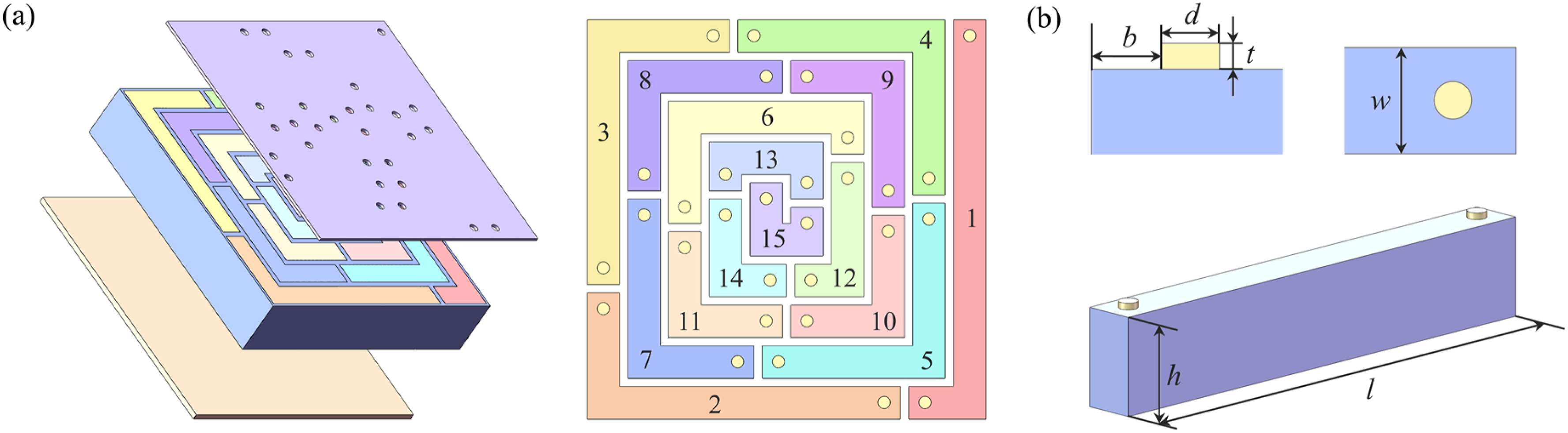
Figure 1(b) presents the detailed structural parameters of a single sound-absorbing unit. Each cavity has a thickness h, a length l, and a width w. The diameter and thickness of each hole are d and t, respectively, and the edge-to-edge distance between each hole and the cavity is b.
2.2. Theoretical analysis
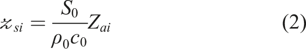
The acoustic surface impedance

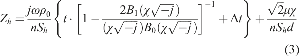
Using the Euler equation (Maa, 1998), the impedance of the neck can be calculated as:

The surface acoustic impedance of the coiled resonant cavity

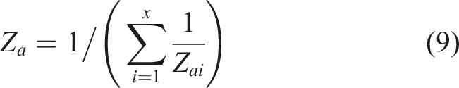
Assuming the thin sound-absorbing metamaterial consists of x identical unit cells, the total surface impedance of the entire structure can be obtained by considering the parallel combination of the impedances of the individual units:
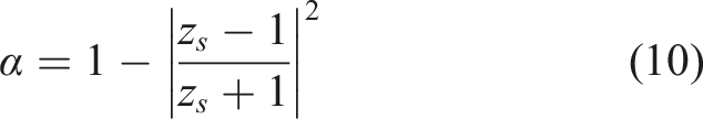
Furthermore, the sound absorption coefficient can be expressed as:
2.3. Construction of the finite element numerical model
A finite element numerical model for calculating the sound absorption coefficient and transmission loss (TL) of the thin sound-absorbing metamaterial can be constructed by using the pressure acoustics and solid mechanics modules in the commercial finite element software COMSOL Multiphysics. In the three-dimensional coordinate system, the model consists, from bottom to top along the positive z-axis, of the incident/reflected sound field, the thin sound-absorbing metamaterial, and the transmitted sound field. Plane-wave radiation boundaries are applied at the ends of the two sound fields to prevent multiple reflections of sound waves. A normal incident sound wave with an amplitude of 1 Pa is applied to one side of the incident/reflected sound field, propagating perpendicular to the structure surface (i.e., along the positive z-axis). To balance model simplification and computational accuracy, the holes and cavities are modeled as narrow region acoustics within the pressure acoustics module to account for thermal and viscous losses.
In general, when the research focus is on calculating the sound absorption coefficient and TL is not required, the model can be simplified to significantly reduce computational cost. In the simplified model, only the incident/reflected sound field and the thin sound-absorbing metamaterial are retained, and the transmitted sound field does not need to be constructed (Sun et al., 2025; Wang et al., 2025b). Furthermore, the calculation requirements can be satisfied by merely enabling the pressure acoustics module in the finite element numerical model.
For ease of subsequent sample fabrication, the solid material of the thin sound-absorbing metamaterial is chosen to be resin. Its Young’s modulus, density, and Poisson’s ratio are 2.5 GPa, 1200 kg/m3, and 0.41, respectively, with a loss factor of 0.05.
2.4. Noise reduction performance analysis
Cavity lengths of the thin sound-absorbing metamaterial used for the case study.
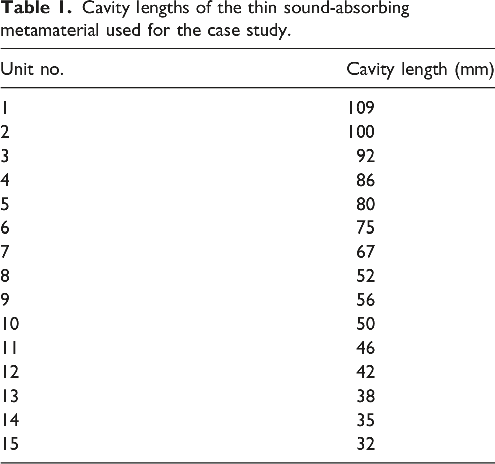
Figure 2(a) shows the theoretical and simulated sound absorption coefficients of the thin sound-absorbing metamaterial for case study, where the simulated sound absorption coefficient is calculated using the finite element numerical model established based on pressure acoustics and solid mechanics in Section 2.3. It is observed that the metamaterial forms 15 consecutive absorption peaks within the frequency range of 600–1600 Hz, and the number of absorption peaks is consistent with the number of designed cavities. Furthermore, the theoretical and simulated absorption curves are in good agreement in terms of frequency distribution, which verifies the accuracy of the theoretical analysis. The effective half-absorption bandwidth of this thin sound-absorbing metamaterial ranges from 732 Hz to 1524 Hz, which covers approximately one octave and demonstrates favorable broadband sound absorption potential. Sound absorption performance of the thin sound-absorbing metamaterial. (a) Simulated and theoretical sound absorption coefficients (A). (b) Complex frequency plane.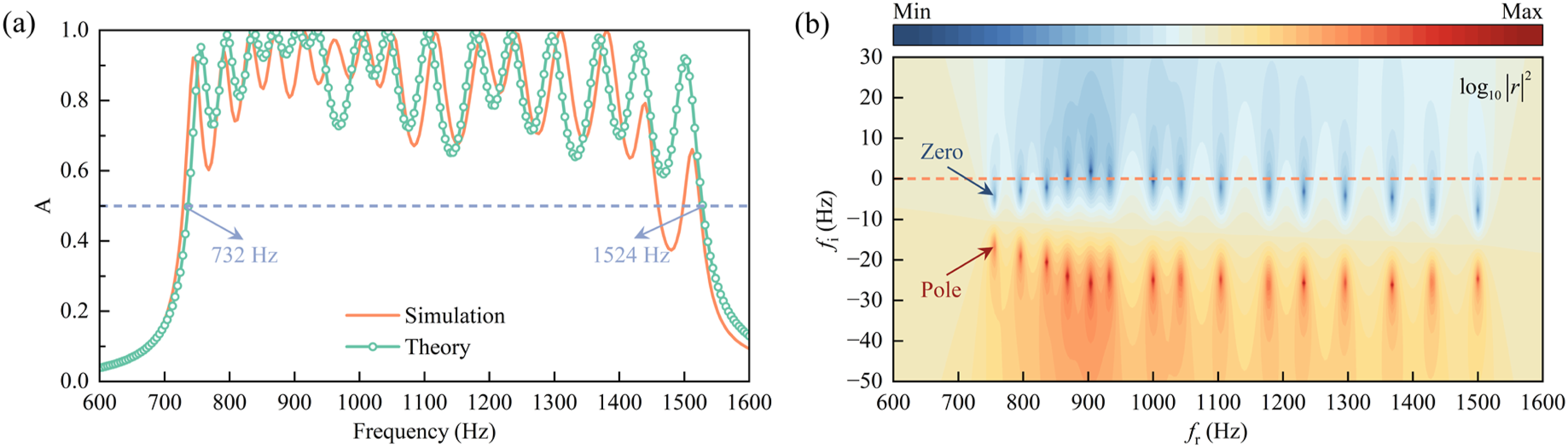
Figure 2(b) presents the complex frequency plane of the thin sound-absorbing metamaterial, which essentially illustrates the distribution of
Figure 3(a) presents the TL results of the thin sound-absorbing metamaterial under free boundary conditions with normal acoustic wave incidence, along with the mass law predictions for a homogeneous plate of the same surface mass density. The results show that this structure forms 15 consecutive TL peaks within the range of 600–1600 Hz, with the number of TL peaks consistent with that of the sound absorption peaks. Within its effective sound absorption bandwidth, the proposed metamaterial can break the constraints of the mass law and achieve an average TL of 42.01 dB, whereas the mass law prediction for the homogeneous plate yields an average TL of only 37.89 dB over the same frequency range. Sound insulation performance of the thin sound-absorbing metamaterial. (a) TL. (b) Comparison of the sound absorption coefficient and TL.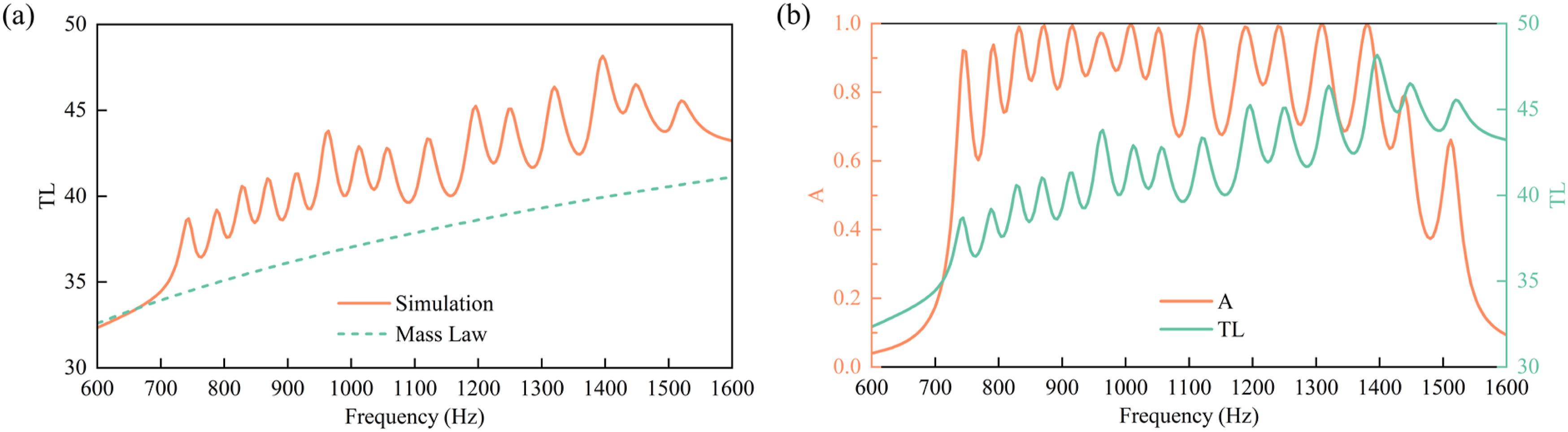
Figure 3(b) compares the sound absorption coefficient and TL curves of the thin sound-absorbing metamaterial. It can be observed that the frequencies of the structure’s sound absorption peaks and TL peaks exhibit an almost one-to-one correspondence. This indicates that the sound insulation performance of this structure originates from its favorable sound absorption performance. By efficiently absorbing the incident sound energy and reducing sound transmission, the sound insulation performance is improved.
3. Parameter analysis and module design
3.1. Parameter analysis
Although the thin sound-absorbing metamaterial has demonstrated excellent broadband sound absorption and sound insulation performance, its effective operating bandwidth covers only approximately one octave. To broaden the operating frequency band, it is necessary to design several thin sound-absorbing metamaterials with different operating frequency bands by adjusting the structural parameters. In the structural design of the thin sound-absorbing metamaterial, the parameters of the perforations and cavities are the core variables for tuning its operating bandwidth and noise reduction performance. The key structural parameters of the perforations include the hole thickness t, hole diameter d, distance from the hole edge to the cavity edge b, and the number of holes. The key structural parameters of the cavity are primarily the cavity width w and cavity thickness h.
Figure 4 shows the effects of hole thickness t and hole diameter d on both the sound absorption and sound insulation performance of the thin sound-absorbing metamaterial, it can be observed that as the hole thickness t increases and the hole diameter d decreases, both the sound absorption and sound insulation operating bandwidth of the thin sound-absorbing metamaterial exhibits a significant low-frequency shift, while its effective operating bandwidth gradually narrows. Parameter analysis of the thin sound-absorbing metamaterial. (a) Hole thickness t. (b) Hole diameter d.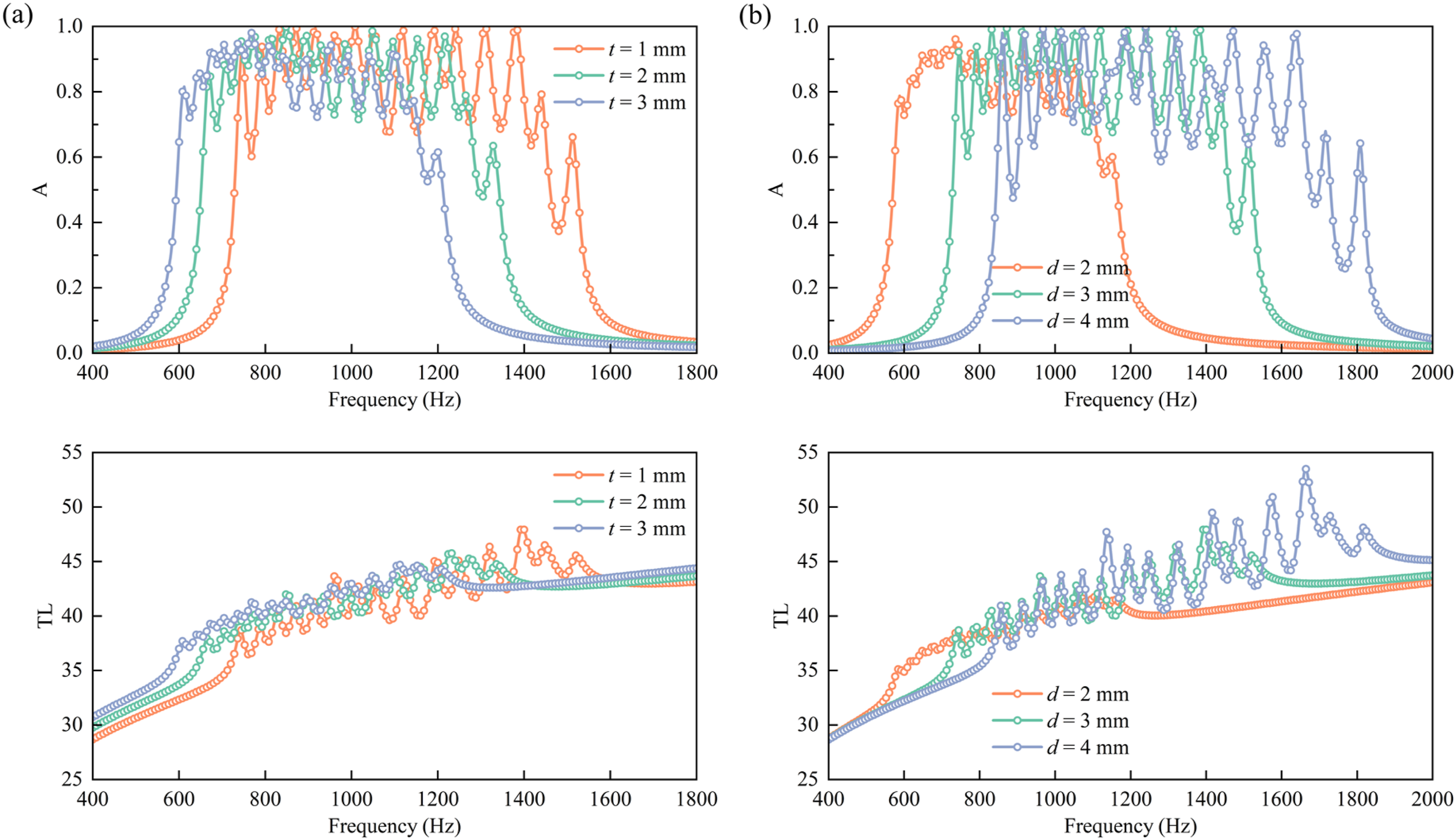
Figure 5(a) shows the effects of the distance from the hole edge to the cavity edge b. It can be observed that as the b increases from 2.5 mm to 6.5 mm, both the sound absorption and sound insulation operating bandwidth of the thin sound-absorbing metamaterial exhibits a slight high-frequency shift, with minimal change in the sound absorption coefficient. Figure 5(b) investigates the influence of the number of holes per cavity and their positions on the sound absorption and sound insulation performance of the thin sound-absorbing metamaterial. Here, “Each side” represents the original double-hole configuration, “One side” represents a single-hole configuration with a hole drilled at one end of each cavity, and “Middle” represents a single-hole configuration with a hole drilled at the center of each cavity. The results show that when the structure is reduced from a double-hole to a single-hole configuration, its operating bandwidth shifts significantly toward lower frequencies. A further comparison of the hole positions in the single-hole configurations reveals that placing the hole on one side of the cavity results in a lower operating bandwidth compared to placing it in the middle. Parameter analysis of the thin sound-absorbing metamaterial. (a) The distance from the hole edge to the cavity edge b. (b) The number of holes.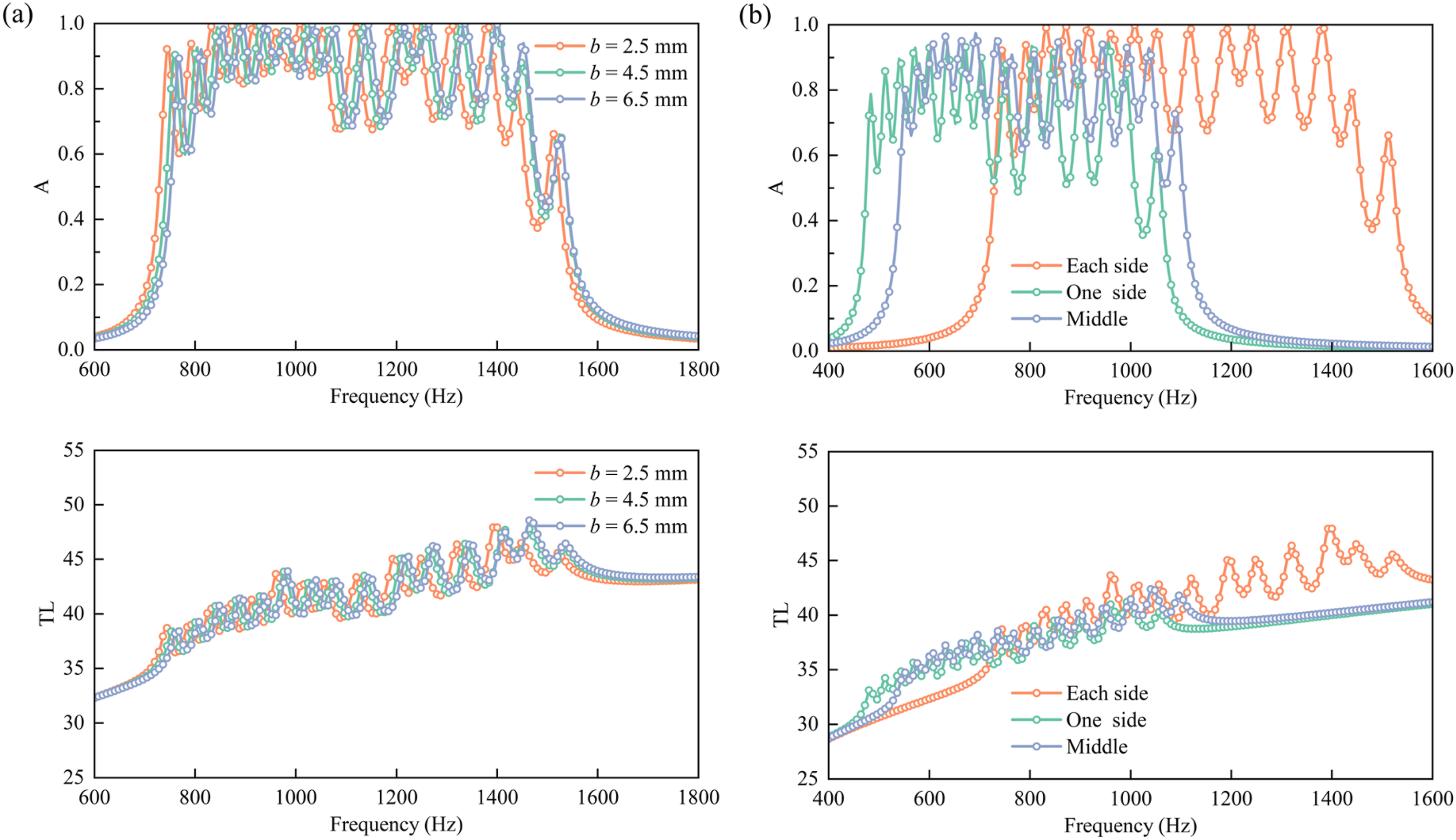
Figure 6 shows the effects of cavity width w and cavity thickness h. It can be observed that as the w and h increase, the operating bandwidth of the thin sound-absorbing metamaterial gradually shifts toward lower frequencies. Parameter analysis of the thin sound-absorbing metamaterial. (a) Cavity width w. (b) Cavity thickness h.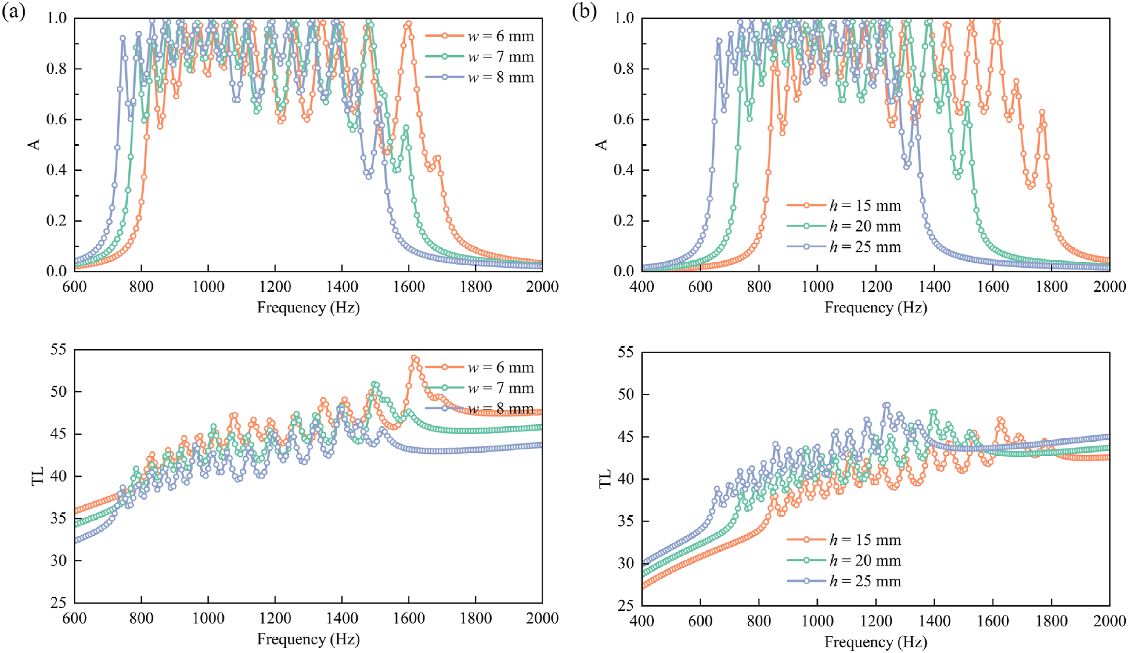
The preceding parameter analysis indicates that the operating bandwidth and noise reduction performance of the thin sound-absorbing metamaterial can be precisely designed through the cooperative tuning of multiple parameters. Furthermore, the influence of these parameters on both the sound absorption and sound insulation bandwidths exhibits a high degree of similarity, a trend also observed in the work of Xia et al. (2026). This further reveals the inherent and close relationship between the sound insulation and sound absorption performance of the thin sound-absorbing metamaterial.
3.2. Module design
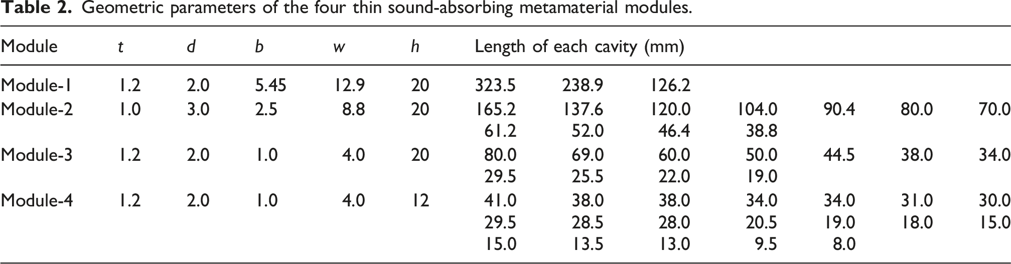
Based on the parameter analysis results, four thin sound-absorbing metamaterial modules with distinct operating bandwidths were designed to achieve broadband noise control. Schematic diagrams of the labyrinthine channels for the four modules are shown in Figure 7(a), and their key structural parameters are listed in Table 2. Among them, Module-1 and Module-2 have a lateral dimension of 100 mm × 100 mm, while Module-3 and Module-4 have a lateral dimension of 50 mm × 50 mm. All modules maintain the same total thickness of 23 mm. Four thin sound-absorbing metamaterial modules. (a) Schematic of the labyrinthine channel. (b) Sound absorption coefficient. Geometric parameters of the four thin sound-absorbing metamaterial modules.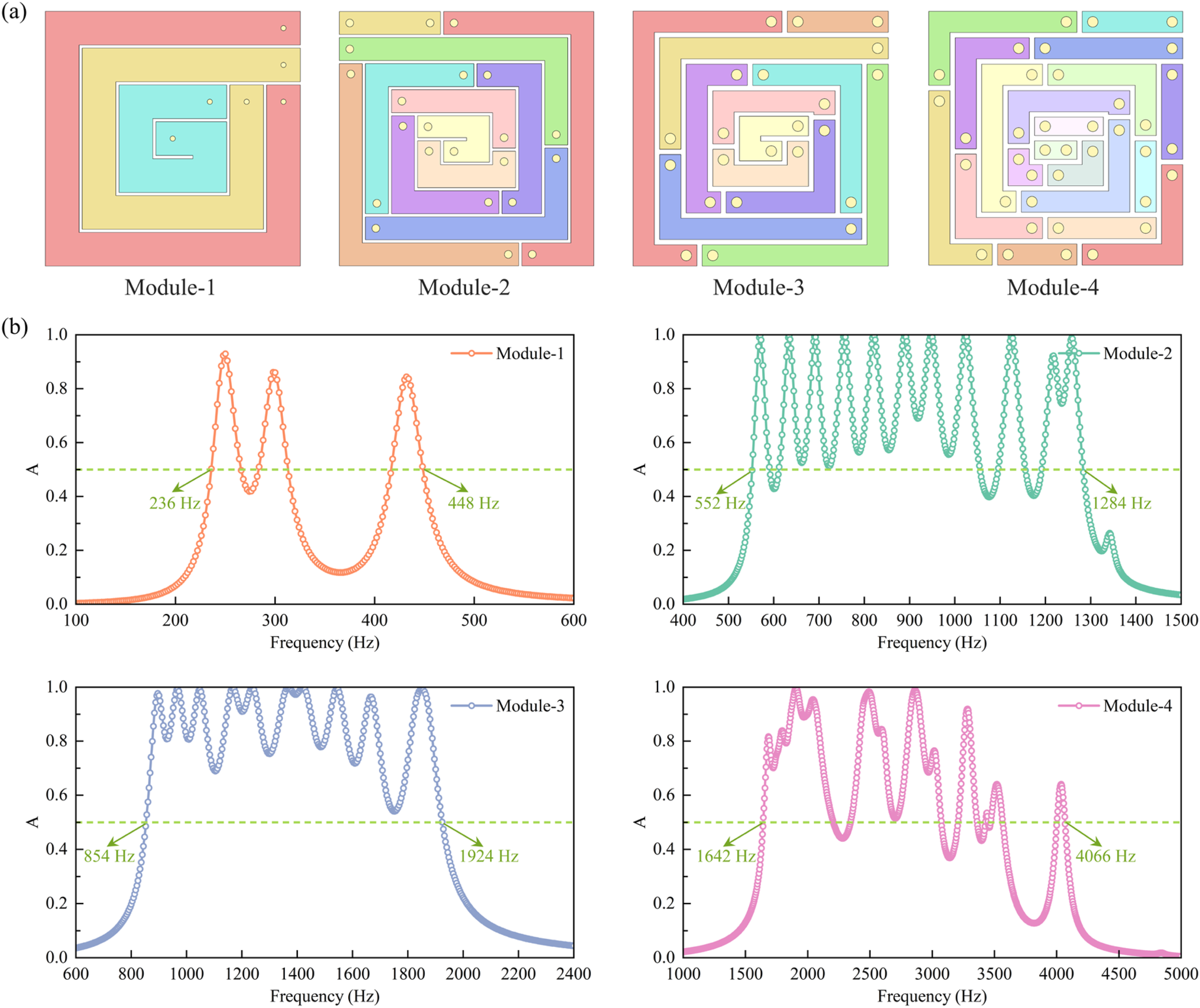
The sound absorption coefficient results for the four modules are presented in Figure 7(b). It can be observed that each module generates a continuous and evenly distributed series of absorption peaks within a specific frequency range. The effective half-absorption bandwidths of Module-1, Module-2, Module-3, and Module-4 are 236–448 Hz, 552–1284 Hz, 854–1924 Hz, and 1642–4066 Hz, respectively. The effective sound absorption frequency band of each individual module covers approximately one octave, enabling precise noise reduction in a specific frequency band. Moreover, integrating the effective bandwidths of the four modules yields a continuous coverage range from 236 to 4066 Hz, spanning multiple octaves.
3.3. Coupling effect analysis
To achieve broadband noise reduction, the in-plane parallel coupling method is usually adopted. To reveal the underlying mechanism of this parallel coupling effect, four sets of thin sound-absorbing metamaterial modules were selected for coupling performance analysis. The results are shown in Figure 8. Investigation of the parallel coupling effect in thin sound-absorbing metamaterials. (a) Parallel coupling results. (b) Sound pressure level contour maps of the Module-2 and Module-3 combination at the frequencies corresponding to points P1 and P2.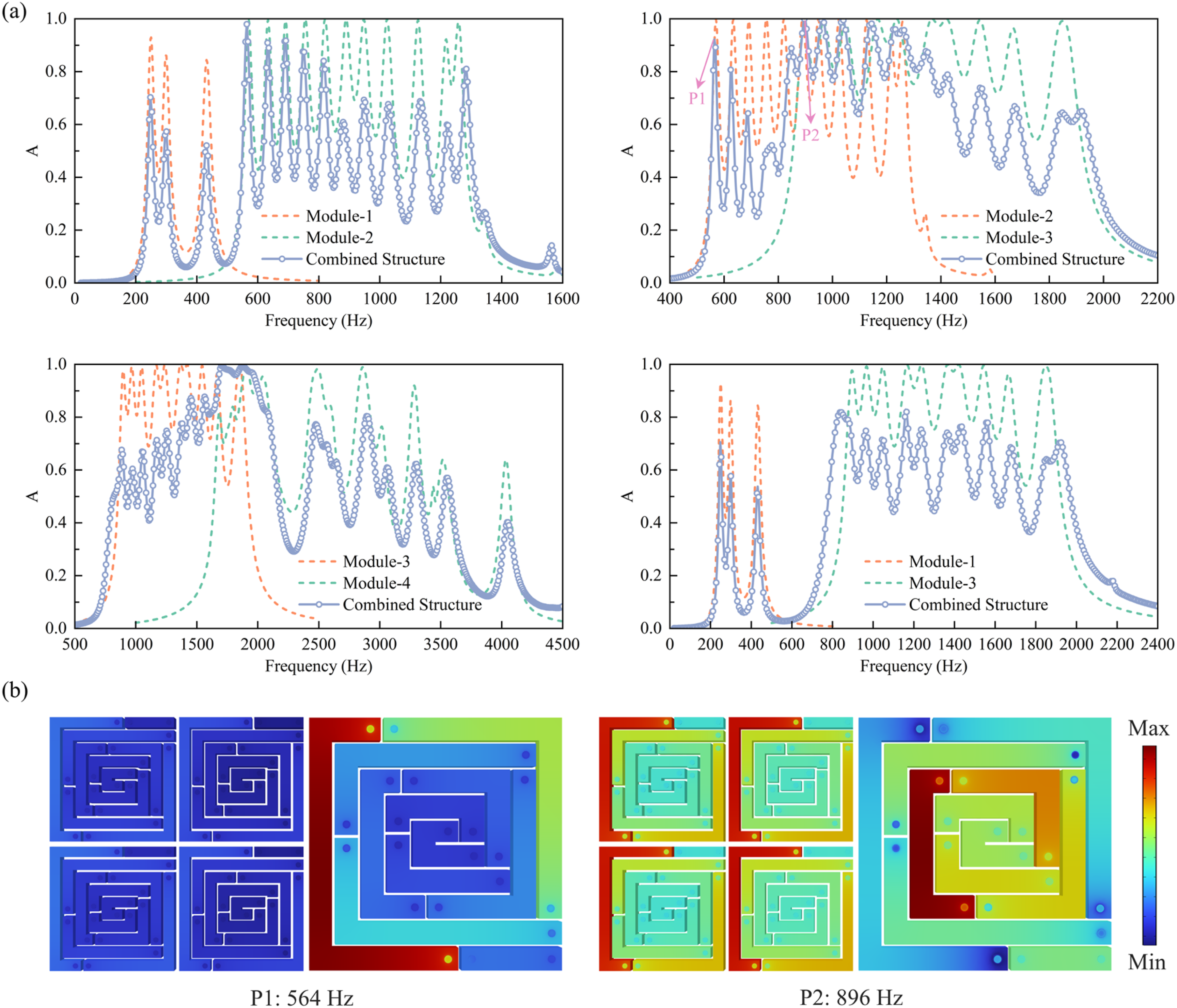
The parallel coupling results for the four sets of modules indicate that in-plane parallel coupling of two modules with different operating bands can achieve the superposition and broadening of their operating frequency ranges. Furthermore, the effective operating band of the combined structure is approximately the linear superposition of the effective bands of the individual modules, thereby verifying the effectiveness of this coupling strategy for bandwidth expansion. From the perspective of absorption amplitude, different frequency regions exhibit distinct characteristics. Specifically, when the operating bands of the two modules do not overlap, the combined structure exhibits amplitude reduction within the operating frequency range. In the overlapping region of the operating bands, the aforementioned amplitude reduction disappears completely. The absorption coefficient of the combined structure not only maintains a high amplitude but also achieves perfect sound absorption, which reflects the performance gain induced by the coupling effect.
To further elucidate the underlying mechanism of multi-module parallel coupling, the combined structure of Module-2 and Module-3 was selected as the research object. Figure 8(b) presents the sound pressure level contour maps of this combined structure at point P1 and point P2. It can be observed that, at point P1, the sound pressure level contour map shows that only one unit in Module-2 (the right module) undergoes strong resonance. The absorption peak in this frequency band is therefore attributed solely to the individual action of the corresponding unit in Module-2. However, the parallel combination of Module-2 and Module-3 impairs the original impedance-matching condition, resulting in a reduction in the sound absorption amplitude, which confirms that the parallel structure has performance limitations caused by impedance mismatch in the non-overlapping region. In contrast, at point P2, in addition to one unit in Module-2 undergoing strong resonance, a unit in Module-3 (the left module) also resonates strongly in tandem. Consequently, the absorption peak at P2 is attributed to the collective action of the corresponding units in both modules, which enhances the sound energy dissipation efficiency and ultimately achieves high-amplitude sound absorption in the overlapping region, even reaching the effect of perfect sound absorption.
In summary, while parallel coupling is an effective strategy for broadening the operational frequency band, its main limitation lies in the potential impedance mismatch in non-overlapping frequency bands, which consequently leads to a degradation of sound absorption performance. Hence, practical engineering application necessitates a systematic trade-off between sound absorption bandwidth and amplitude. If bandwidth expansion is prioritized, some performance loss in isolated frequency ranges may be tolerated. Conversely, if stringent absorption intensity is required in specific bands, the design of different absorption modules must be carefully executed. This involves a thorough consideration of the overall structural impedance matching to avoid further performance deterioration caused by inter-module impedance interference.
4. Design and experimental testing of acoustic metamaterial enclosure
4.1. Design of the acoustic metamaterial enclosure
For typical irregular noise sources in industrial settings (such as cylindrical motors), this paper proposes a curved acoustic metamaterial enclosure based on a polygon-fitting design approach, enabling efficient adaptation to curved noise sources. The design concept of polygon-fitting is illustrated in Figure 9(a). Based on fundamental geometric principles, the shape of a polygon approaches a circle as the number of sides increases. When the number of sides reaches nine, the polygon can sufficiently approximate a circular curved surface. Further increasing the number of sides does not significantly improve the fitting accuracy to the curved surface but substantially increases the complexity of the enclosure’s structural design and manufacturing. Therefore, this study selects a regular nonagon as the fundamental geometric configuration for the enclosure. Based on the regular nonagon configuration, the vertices are further optimized, ultimately forming a continuous curved surface via the fitting of 18 segmented lines, comprising nine long sides and nine short sides arranged in an alternating manner. The overall structure is illustrated in Figure 9(b), which adopts a split-type design consisting of a main body and an upper cover. Overall structure of the acoustic metamaterial enclosure: (a) Polygon-fitting design concept. (b) Schematic of the overall structure.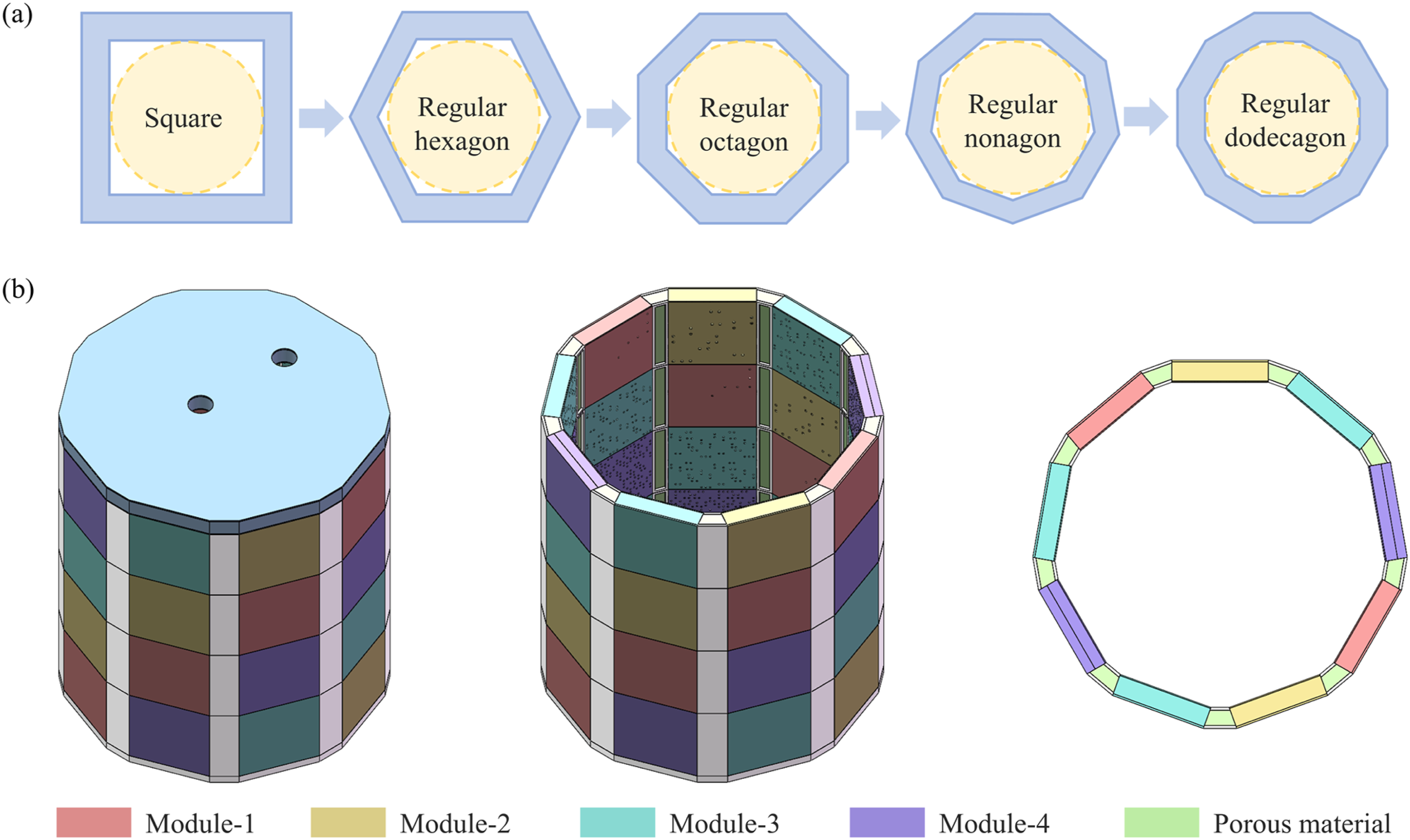
To accommodate the cable connection requirements of noise sources in industrial settings, two circular holes with a diameter of 30 mm are drilled through the upper cover of the acoustic metamaterial enclosure to allow cables to pass between the internal noise source and external control systems. As for the main body of the acoustic metamaterial enclosure, each of the nine long sides is composed of the four types of thin sound-absorbing metamaterial modules designed in Section 3.2, with every layer of the main body containing all four modules. This configuration ensures consistent and continuous broadband noise reduction performance in all directions, effectively avoiding circumferential performance variations that could result from concentrating a single module. Furthermore, it leverages the synergistic advantages of the multiple modules across different frequency bands to achieve broadband sound absorption. The nine short sides are filled with porous material. This design not only enables efficient material packing within the narrow space of the short sides, enhancing the overall space utilization of the structure, but also improves the noise reduction performance in the mid-to-high frequency range. The designed acoustic metamaterial enclosure has a height of 410 mm, an inner diameter of approximately 337 mm, and a maximum wall thickness of 23 mm. The porous material employed in the structure has a thickness of 15 mm. It is worth mentioning that, to meet the noise control requirements of larger-scale noise sources, the proposed curved configuration design can achieve the expansion of the enclosure’s diameter and height by increasing the number of polygon-fitting sides and the enclosure height. During this process, the geometric parameters and resonance characteristics of each individual thin sound-absorbing metamaterial module remain unchanged, and only the total number of modules arranged in parallel changes. Increasing the number of modules does not alter the equivalent acoustic impedance per unit area of the overall structure, thereby preserving the parallel coupling effect between modules and thus ensuring the effectiveness of the acoustic metamaterial enclosure’s broadband noise reduction capability on a larger scale.
4.2. Experimental testing of the acoustic metamaterial enclosure
To validate the effectiveness of the designed acoustic metamaterial enclosure, an experimental prototype was fabricated using 3D printing technology. A photograph of the prototype is shown in Figure 10(a), which has a surface mass density of 9.8 kg/m2. The noise reduction performance of the enclosure was tested in a reverberation room, as illustrated in Figure 10(b). The enclosure was placed at the center of the room, and a loudspeaker was positioned inside to serve as the noise source. The noise type was set as broadband white noise. The loudspeaker cable was routed through the pre-drilled hole to connect to external equipment. To prevent sound leakage, the gaps between the hole and the cable, as well as the joint between the main body and the top cover of the enclosure, were sealed with clay. To comprehensively evaluate the sound field distribution characteristics around the acoustic metamaterial enclosure, four microphones (Mic-1, Mic-2, Mic-3, and Mic-4) were uniformly arranged at a height of 0.3 m from the ground and a horizontal distance of 1 m from the enclosure, along its front, rear, left, and right azimuths, for collecting sound pressure data in different horizontal directions. In addition, an extra microphone (Mic-5) was deployed 1 m directly above the enclosure to specifically characterize its acoustic radiation characteristics in the vertical direction. Experimental testing of the acoustic metamaterial enclosure. (a) Experimental prototype photograph. (b) Experimental setup photograph.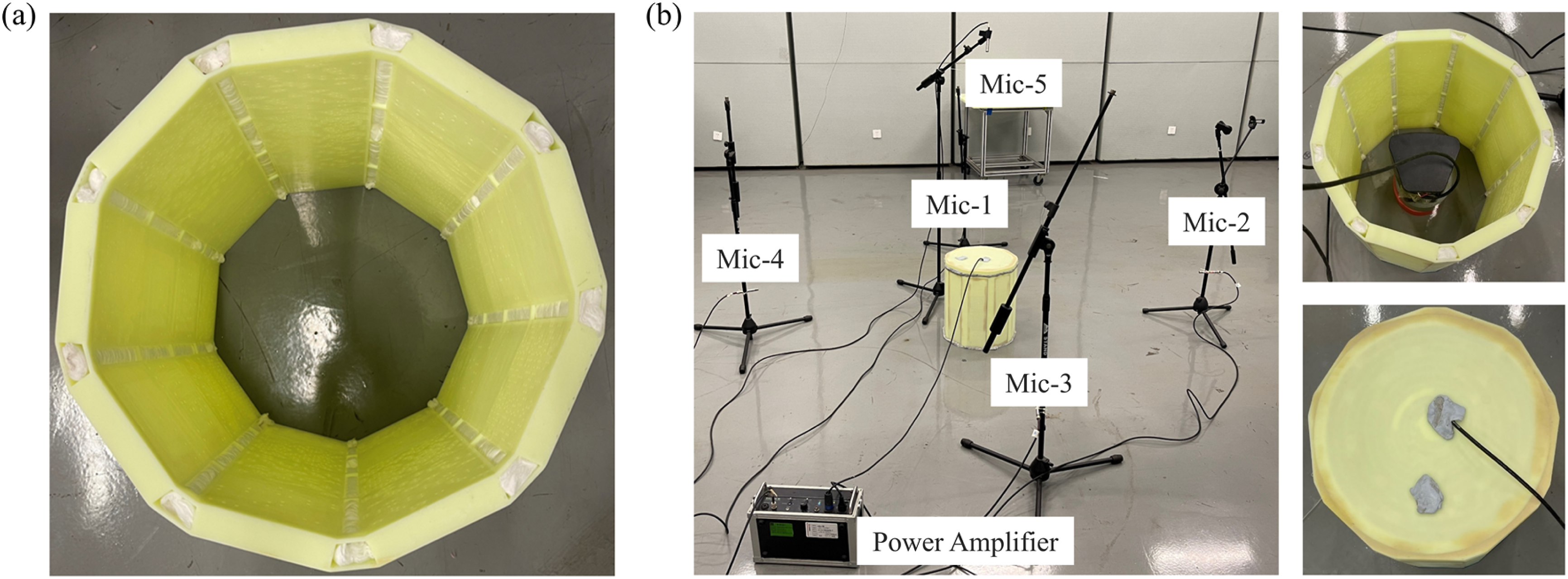
For data analysis, the sound pressure data from the five microphones were averaged to provide a comprehensive evaluation of the enclosure’s acoustic performance. The resulting sound pressure level spectrum for the enclosure is shown in Figure 11(a). For comparison, the sound pressure level data for a conventional leather enclosure are also presented. The conventional leather enclosure features a double-layer composite structure consisting of a sound insulation layer and a sound absorption layer. The sound insulation layer is made of 1.5 mm thick ethylene propylene diene monomer rubber, while the sound absorption layer is composed of 15 mm thick polyester fiber acoustic cotton. Its outer contour diameter corresponds to the inscribed circle diameter of the inner contour of the acoustic metamaterial enclosure, ensuring that the comparison is conducted under similar external installation spatial constraints. The surface mass density of the conventional leather enclosure is 5.2 kg/m2. The results show that, within the range of 200-2000 Hz (with only a slight performance fluctuation observed at 1600 Hz), the sound pressure level of the acoustic metamaterial enclosure is consistently lower than that of the conventional leather enclosure, demonstrating superior broadband noise reduction capability. Within this frequency range, without any sound insulation, the total sound pressure level of the white noise is 80.53 dB. With the conventional leather enclosure, the total sound pressure level is reduced to 62.57 dB, corresponding to a noise reduction of 17.96 dB. In contrast, the acoustic metamaterial enclosure further reduces the total sound pressure level to 52.16 dB, achieving a noise reduction of 28.37 dB. Compared with the conventional leather enclosure, the noise reduction effect is significantly improved by 10.41 dB. Within the frequency range of 200–5000 Hz, without any sound insulation, the total sound pressure level of the white noise is 86.58 dB. The conventional leather enclosure reduces the total sound pressure level to 62.71 dB, corresponding to a noise reduction of 23.87 dB. The acoustic metamaterial enclosure further decreases the total sound pressure level to 56.61 dB, achieving a noise reduction of 29.97 dB, which is a significant improvement of 6.1 dB over the conventional leather enclosure. Experimental testing results of the acoustic metamaterial enclosure. (a) Measured sound pressure level. (b) Processed insertion loss.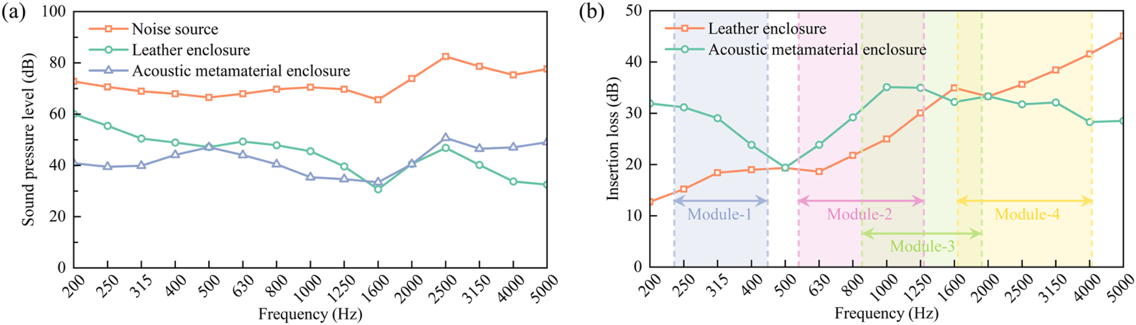
To present the noise reduction effectiveness of the acoustic metamaterial enclosure more intuitively, Figure 11(b) shows the insertion loss curves for both the acoustic metamaterial enclosure and the conventional leather enclosure at the 1/3-octave center frequencies within the range of 200–5000 Hz. The analysis reveals that the core advantage of the acoustic metamaterial enclosure lies in the low-to-mid frequency range. In the 200–1250 Hz range, the acoustic metamaterial enclosure has a higher insertion loss compared with the conventional leather enclosure. Especially in the 200–315 Hz low-frequency band, its performance enhancement exceeds 10 dB. This effectively addresses the challenge faced by conventional materials in achieving efficient low-frequency noise reduction with thin-layer structures. Furthermore, a closer examination reveals that the actual noise reduction frequency band of the acoustic metamaterial enclosure is in good agreement with the designed operating bands of the four thin sound-absorbing metamaterial modules employed. Within the designed operating frequency range, the acoustic metamaterial enclosure demonstrates superior noise reduction performance, except in the mid-to-high frequency range, thus verifying the effectiveness of the proposed design method.
In the performance comparison between the acoustic metamaterial enclosure and the conventional leather enclosure, the acoustic metamaterial enclosure is slightly thicker than the latter. Moreover, as it is primarily fabricated using resin 3D printing without fully considering material utilization efficiency, its surface mass density is correspondingly higher. To fairly compare the noise reduction performance of the two enclosures, two complementary metrics are adopted for evaluation. First, the insertion loss per unit surface mass density is calculated to assess the material utilization efficiency of both enclosures:
However, the above metric only reflects the mass efficiency. To separate the contribution of the structural design of the acoustic metamaterial from its own mass effect, the excess insertion loss relative to the mass law was further quantified. According to the mass law, the transmission loss of a single-layer homogeneous panel is given by:
Furthermore, this study also aims to explore from an engineering application perspective whether the metamaterial design can overcome the performance limitations of conventional acoustic material systems under the constraint of similar external installation space. The experimental results demonstrate that, despite increases in thickness and surface mass density, the acoustic metamaterial enclosure achieves an improvement in average noise reduction of 10.41 dB in the 200–2000 Hz frequency range and 6.1 dB in the 200–5000 Hz range. This realizes low-frequency broadband noise reduction effects that are difficult to achieve with conventional materials within limited thickness.
The comparison between the conventional reflective enclosure and the acoustic metamaterial enclosure reveals fundamentally distinct performance enhancement mechanisms. Conventional reflective enclosures rely on the mass law, where their noise reduction capability is strongly positively correlated with structural thickness and mass, often requiring substantial increases in volume and weight for limited performance gains. In contrast, the acoustic metamaterial enclosure proposed in this study relies on the “sound insulation via absorption” sound energy dissipation mechanism, demonstrating superior performance in mid-to-low frequency noise reduction within a limited thickness that is difficult for conventional materials to match. Therefore, this study not only validates the feasibility of acoustic metamaterials in realizing high-performance and lightweight enclosures, but also demonstrates a design pathway to break the entrenched trade-off between mass and acoustic performance.
4.3. Design and experimental testing of the single-module acoustic metamaterial enclosure
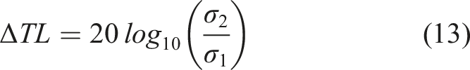
To further verify the engineering feasibility of the acoustic metamaterial enclosure, a single-module acoustic metamaterial enclosure composed of a single thin sound-absorbing metamaterial module and porous materials was fabricated. The thin sound-absorbing metamaterial module adopted herein is Module-2 designed in Section 3.2, and the overall structure of this enclosure is shown in Figure 12(a), with a surface mass density of 6.74 kg/m2. Experimental tests on its noise reduction performance were carried out in a full anechoic room, with three repeated measurements conducted. The test environment is presented in Figure 12(b). Compared with the test environment in Section 4.2, the sound level meter was placed at 1 m directly in front of the enclosure at a measuring height of 0.3 m in this experiment for sound pressure data acquisition. Experimental testing of the single-module acoustic metamaterial enclosure. (a) Experimental prototype photograph. (b) Experimental setup photograph.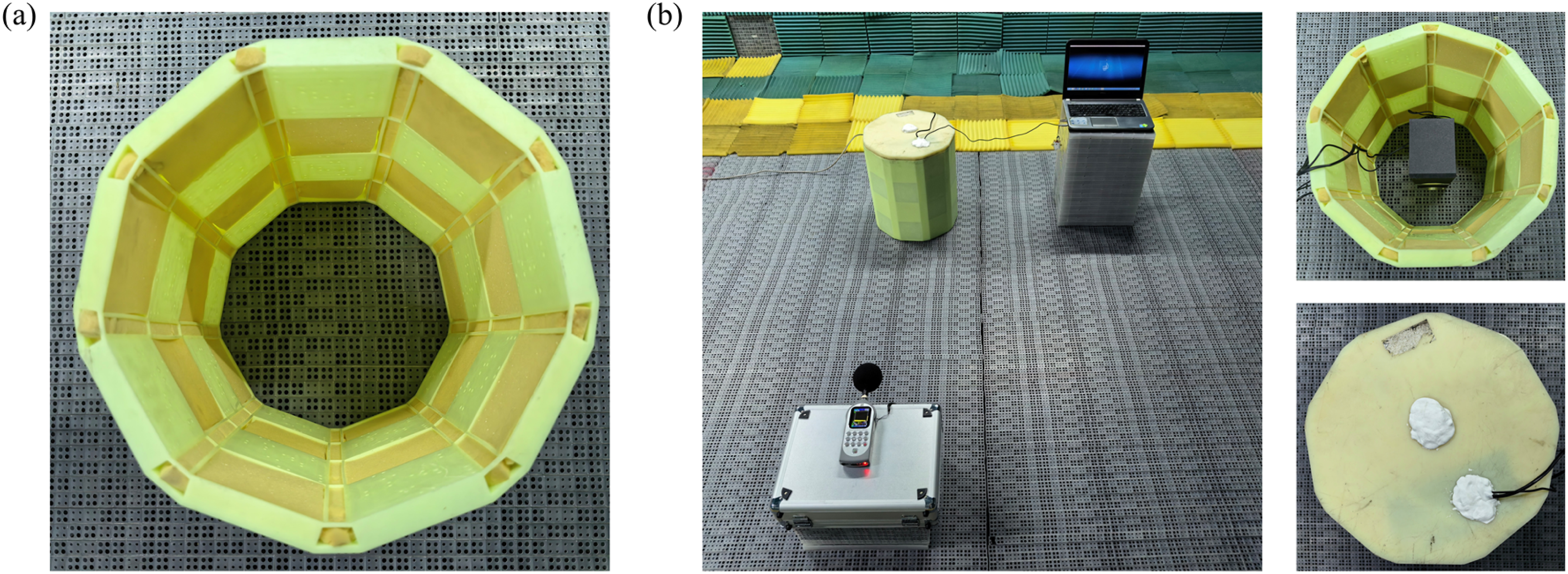
The test results of the sound pressure level spectrum and insertion loss of the single-module acoustic metamaterial enclosure are shown in Figure 13(a) and (b), respectively, with the error bands derived from the three experimental tests. The results demonstrate that the enclosure exhibits favorable noise reduction performance over the entire tested frequency range. Specifically, in the 200–5000 Hz frequency band, the total sound pressure level of white noise without any sound insulation measures is 83.22 dB, while it decreases to 55.99 dB after installing the single-module acoustic metamaterial enclosure, achieving a noise reduction of 27.23 dB. In addition, the enclosure delivers favorable noise reduction performance within the designed operating frequency band of Module-2. The above experimental results further verify the feasibility and practicability of acoustic metamaterials for fabricating high-performance, lightweight enclosures. Experimental testing results of the single-module acoustic metamaterial enclosure. (a) Measured sound pressure level. (b) Processed insertion loss.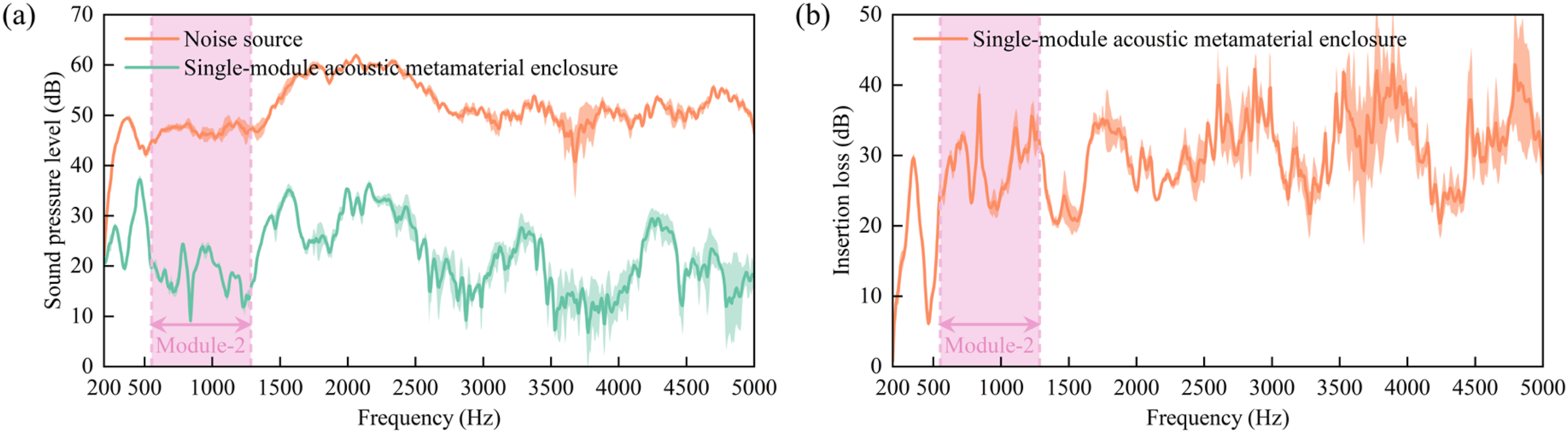
5. Conclusions
To address the challenges that conventional reflective enclosures are susceptible to sound leakage and that thin porous materials are ineffective in isolating low-frequency noise, this paper proposes a curved acoustic metamaterial enclosure composed of a composite of thin sound-absorbing metamaterials and thin porous materials. This design achieves an overall thin profile while enabling efficient noise reduction over a low-frequency broadband range. Based on the in-plane space-coiling design concept, the thickness dimension required for the sound-absorbing structure is shifted within the thin planar layer, effectively reducing the overall wall thickness of the enclosure. Furthermore, by adopting a design with multiple metamaterial modules coupled in parallel, the bandwidth limitation of a single metamaterial module is effectively overcome, thereby broadening the noise reduction frequency coverage of the enclosure. Through the sound energy dissipation mechanism of “sound insulation via absorption”, the structure can mitigate the degradation of sound insulation performance caused by sound leakage through gaps. Experimental test results show that the designed acoustic metamaterial enclosure can achieve excellent noise reduction performance with a wall thickness of 23 mm in the low-frequency broadband range of 200–5000 Hz. Compared with the conventional reflective leather enclosure, its noise reduction effect is improved by 6.1 dB, and the advantage reaches 10.41 dB especially in the 200–2000 Hz range. This successfully achieves the dual advantages of a thin profile and efficient low-frequency broadband noise reduction. Additionally, the enclosure offers advantages such as simple structure, easy realization of curved configurations, and high space utilization, making it suitable for noise control in small-to-medium-sized electromechanical equipment with limited installation space, and indicating considerable engineering application potential.
However, as a proof-of-concept study, there are certain limitations that need to be acknowledged. On one hand, while the proposed design achieves the dual goals of a thin profile and low-frequency broadband noise reduction, the current prototype is fabricated using resin-based 3D printing without fully considering material utilization efficiency. Consequently, it still exhibits disadvantages in weight and manufacturing cost compared with conventional composite materials, which limits its application and popularization in cost-sensitive engineering scenarios to a certain extent. On the other hand, the present experimental tests were conducted solely under controlled laboratory conditions, and do not fully replicate the complex operational conditions encountered in real-world engineering settings, such as the effects of extreme temperature and humidity, complex airflow disturbance, structural-vibration coupling, and other factors on the acoustic performance of the enclosure. The engineering applicability of the obtained test results thus requires further validation.
Based on the aforementioned limitations, future research efforts will therefore focus on the following directions for further investigation and optimization. First, develop suitable lightweight composite materials and explore low-cost manufacturing processes compatible with large-scale production (e.g., molding or injection molding) to substantially reduce the weight and unit manufacturing cost of the enclosure while preserving its acoustic performance, thereby enhancing its engineering feasibility. Second, investigate the influence mechanisms of complex working conditions including extreme temperature and humidity, vibration and airflow on the acoustic performance of the enclosure. This will involve targeted optimization of material selection and structural design to enhance the environmental adaptability and long-term operational reliability of the enclosure. Third, expand the functional integration dimensions of the acoustic metamaterial enclosure by combining practical features such as thermal insulation, waterproofing, and ventilation with noise control capabilities, thereby broadening its application scenarios and enhancing its engineering value.
In summary, this study proposes a novel acoustic metamaterial enclosure scheme targeting the noise control requirements of small-to-medium-sized electromechanical equipment, verifies the feasibility of its low-profile design and high-efficiency noise reduction performance, and the relevant design methods can provide practical references for the research and development as well as engineering application of similar acoustic devices in subsequent work.
Footnotes
Funding
The authors disclosed receipt of the following financial support for the research, authorship, and/or publication of this article: This work is supported by the National Natural Science Foundation of China (NSFC) under Grant No. 52250287, and Outstanding Youth Science Fund Project of Shaanxi Province under Grant No. 2024JC-JCQN-49.
Declaration of conflicting interests
The authors declared no potential conflicts of interest with respect to the research, authorship, and/or publication of this article.