
Abstract
With growing adoption of body-caudal-fin (BCF)-based bionic propulsion robots, optimizing thrust generation has become a critical focus of research. Despite extensive experimental efforts, theoretical studies in this area remain insufficient. This paper attempts to simplify the swing of the caudal fin as a rotation problem of the hub-beam system. Employing the Euler–Bernoulli beam theory to describe the elastic deformation of the beam and the Morison equation to describe the hydrodynamic load, the governing equation of this system is derived based on the principle of virtual work. We then investigate the effects of material properties, motion parameters, and structural parameters on thrust generation. Our model suggests that the flexibility of the beam can greatly increase instantaneous thrust. In addition, the thrust calculated by our model agrees well with the experiment results. Our work can provide guidance on choosing the proper material and rotation mode to improve propulsion performance in the design of BCF bionic robots.
1. Introduction
Underwater flexible bionic robots have become increasingly popular in recent years. Compared with the traditional propeller-driven autonomous underwater vehicle, body-caudal-fin (BCF) bionic propulsion robots are more efficient, mobile, bio-friendly, and concealable [1–4]. Therefore, BCF bionic propulsion robots have numerous potential applications in maritime research, underwater creature and environment monitoring, and deep-sea resource exploration [5–7]. However, there are still challenges in optimizing and controlling bionic flexible structures.
The caudal fin is a major source of thrust generation in fish utilizing BCF mode. Using the volume imaging system which is capable of taking three-dimensional instantaneous pictures of wake flow patterns, Lauder [8] investigated the motion patterns of fish and fins, as well as their influence on water flow patterns. Flammang et al. [9] conducted experiments and simulations on the fins of ray-finned fish, investigating how flexible the fin rays are and how flexibility influences their response to environmental disturbances. There are numerous caudal fin constructions in the current bionic structure design, including trapezoidal, rectangular, bio-inspired shapes, or some other geometries. The stiffness of the caudal fin is determined by the involved geometric shapes and the elastic modulus of the material. Experiment reveals that caudal fins with varying stiffness have distinct propulsion properties [10,11] and, within a certain range, there is a positive correlation between thrust and flexibility [12–15]. Through numerical simulation, several studies were carried out to investigate the influence of caudal fin shape on the propulsion mechanism [16,17]. Zhong et al. [18] provided a simple tuning strategy for the caudal stiffness of the fish-like robot so that the bionic fish can double the swimming efficiency at tuna-like frequencies and speeds.
Nevertheless, an analytical model for the caudal fin swing problem is still missing. This absence significantly hinders the analysis of displacement and stress distribution within the caudal fin during motion. This motivates us to develop a rigid-flexible coupling dynamic model. This new model mimics a rotating beam and is essential for accurately describing the swing and deformation of the caudal fin. Notice that modeling the large deformations and material nonlinearities of such flexible biomimetic structures is grounded in the theoretical framework of nonlinear continuum mechanics, as formulated in finite elasticity theory [19,20].
Several models of in-plane motion of rotating flexible beams were developed by deriving the governing equation based on the Hamilton principle and the Euler–Bernoulli beam theory, with further considering the influence of bending and stretching deformation [21–24]. The Timoshenko beam theory was also used to study the deformation of flexible beams [25]. Based on this and further considering the influence of inertial effects such as centrifugal and Coriolis forces on bending stiffness, the bending and tensile deformation of the beam were studied [26,27]. Furthermore, for beams of arbitrary shape, the nonlinear rigid-flexible coupling model was developed based on the continuum mechanics containing the finite bending, shearing, stretching, and large-scale motion [28–30]. In order to study the rotating problem of a beam with tip mass, Zhu and Yuan established models based on the Euler–Bernoulli beam [31] and Timoshenko beam theories [32], and examined the axial deformation and deflection of the beam. As the main deformation in the rotating beam, controlling the transverse deformation is the key factor. It was found that controlling the transverse displacement of the beam was consistent with the dynamic stiffness control [33,34]. By applying the Frobenius approach, Wright et al. [35] obtained the exact frequencies and mode shapes for a rotating beam. Liu and Lu [36] developed a hub-beam system with consideration of three-dimensional motion and the interaction among large-scale overall motion, torsional deformation, and longitudinal deformation. These studies, along with advanced modeling techniques for complex structures [37,38], highlight the sophistication achievable in structural dynamics. However, the above-mentioned investigations have not taken the hydrodynamic load into consideration.
In this study, we endeavor to integrate the Morison equation [39–42] with the rotating Euler–Bernoulli beam theory [43,44] to formulate a comprehensive rigid-flexible coupling dynamic model for the rotating beam. This model will significantly enhance our capacity for analyzing the instantaneous thrust generated by a fixed-axis rotating beam. Furthermore, it holds substantial potential for guiding the design of BCF biomimetic propulsion robots, offering valuable insights and practical applications in the field of robotic design and engineering.
The organization of the paper is as follows. In section 2, the mathematical model for the rigid beam is developed, considering the hydrodynamic loads during rotation. Section 3 presents the detailed flexible beam model where beam flexibility and its influence on the thrust generation are discussed. Section 4 details the numerical simulations and experimental validation to verify the proposed theoretical model. Section 5 investigates the thrust generation mechanism in depth, and section 6 concludes this study.
2. Rigid beam model
In this section, we propose a rigid model for the hub-beam system, as illustrated in Figure 1. A uniform beam of length L, width b, height h, density
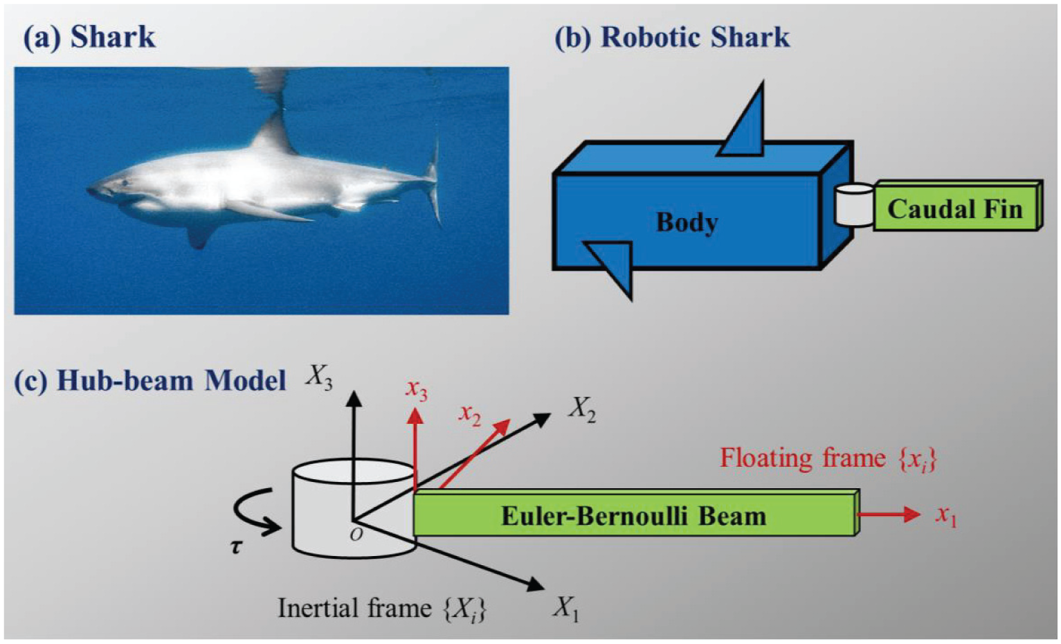
A BCF propulsion model based on the hub-beam system.
The position vector

where the relationship between the base vectors of the inertial frame and the floating frame satisfies

or

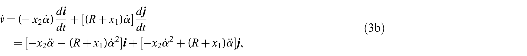
Consequently, the velocity
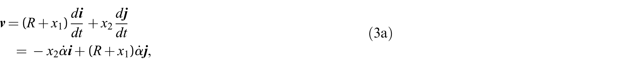
and
where
Similarly, the virtual displacement of an arbitrary point on the beam can be written as follows:

The hydrodynamic forces acting on any point of the beam can be expressed using the differential form of the Morison equation [39], including both the drag force d
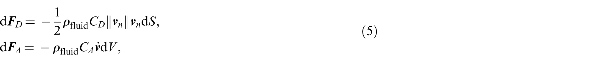
where
In addition to the hydrodynamic forces, the inertial forces due to the beam motion and mass distribution must also be accounted for. These inertial forces are expressed as follows:

Therefore, the total virtual work
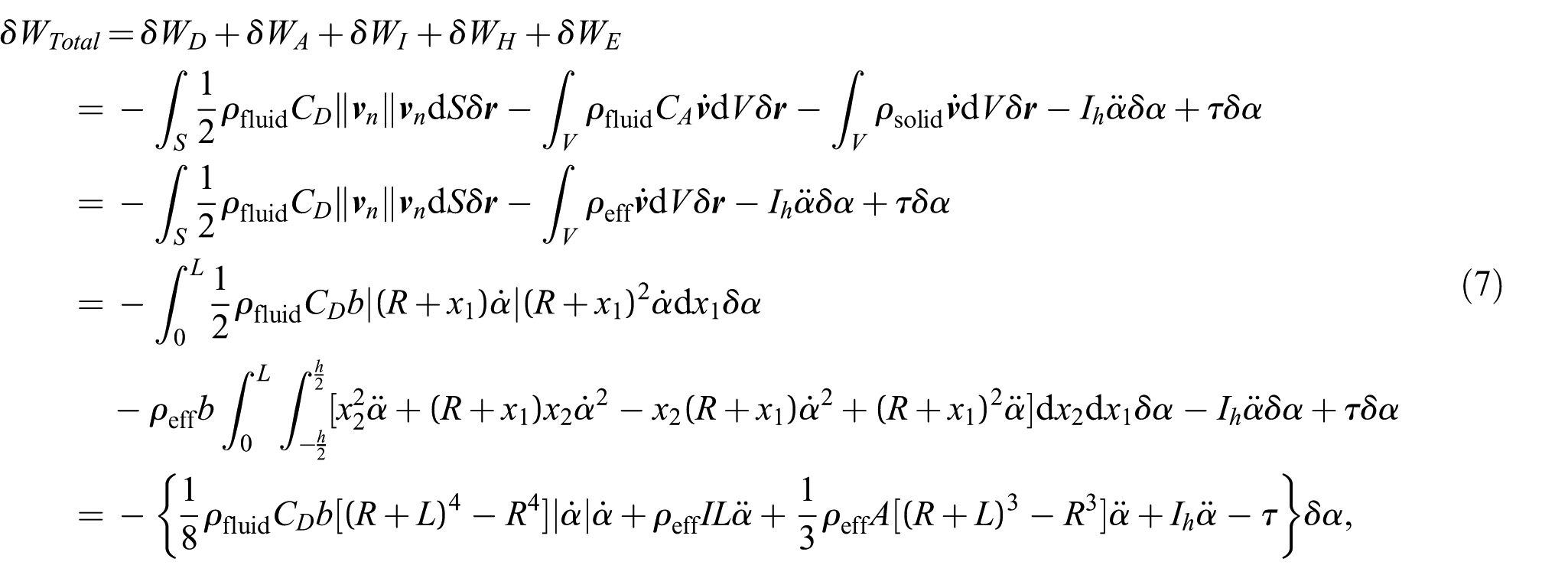
where

Using the principle of virtual work

Furthermore, based on equations (2a), (3), (5), and (6), the instantaneous thrust force along OX1-axis generated by the rotational motion of the beam around OX3-axis can be calculated as follows:
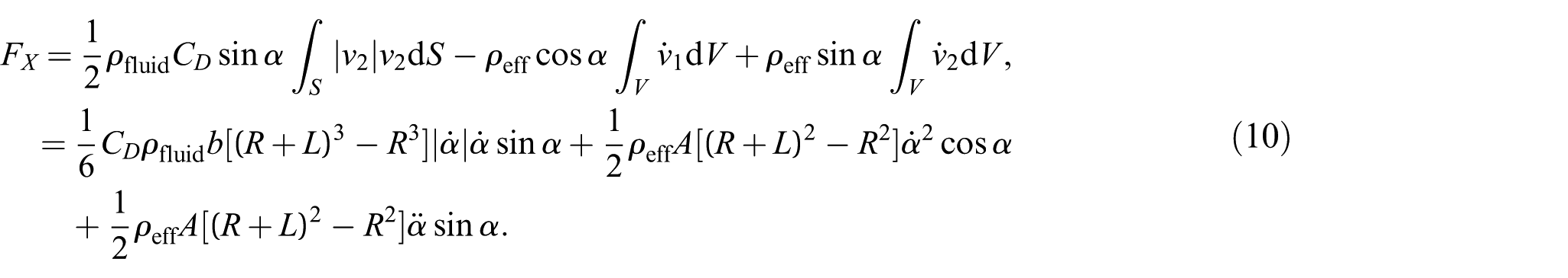
We point out again that equation (10) is the expression for the horizontal thrust force in the rigid hub-beam system when it is under the rotation. In the next section, we derive the solution for the same horizontal thrust force by assuming that the beam is flexible.
3. Flexible beam model
Based on the rigid beam model from the previous section, flexible deformations are introduced using Euler–Bernoulli beam theory, leading to the governing equations for the flexible hub-beam system. The equations are then nondimensionalized to facilitate computation and highlight the key dimensionless parameters that govern the system dynamics.
3.1. Governing equations of the flexible beam
The flexible deformations of the beam are described in the floating frame o-x1x2x3. A point on the neutral axis ox1 of the beam in its undeformed state moves to a new position under deformation. According to Euler–Bernoulli theory, for slender beams, deformations are primarily assumed to be bending, with the shear effect being neglected. In terms of this theory, the displacement field of the beam is defined as a function of the longitudinal position x1 as follows [23]
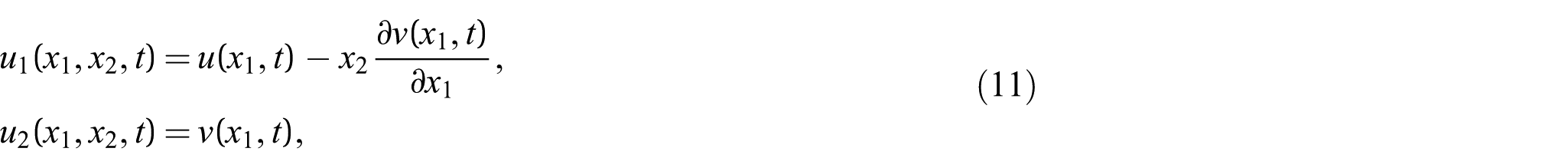
where u and v (distinguished from the velocity vector
Following the same approach as in the rigid beam model, we modify the expression in equation (1) using equation (11) to account for the deformation. Therefore, the position vector of a point on the deformed beam, as expressed in the inertial frame O-X1X2, can be written as

where the prime notation
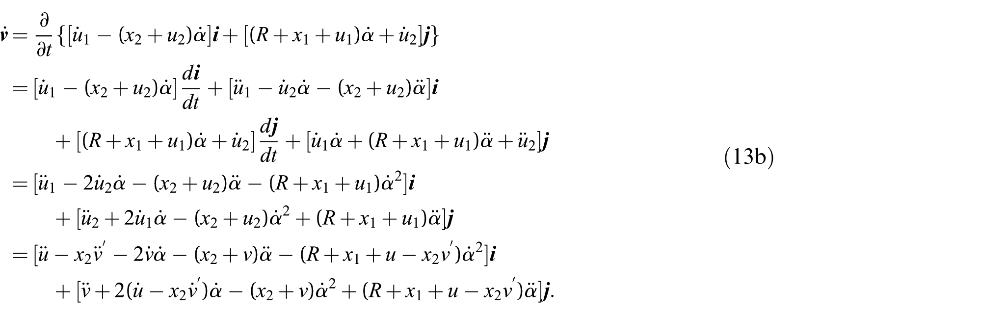
The velocity and acceleration at a point on the deformed beam can be expressed as the time derivatives of the position vector
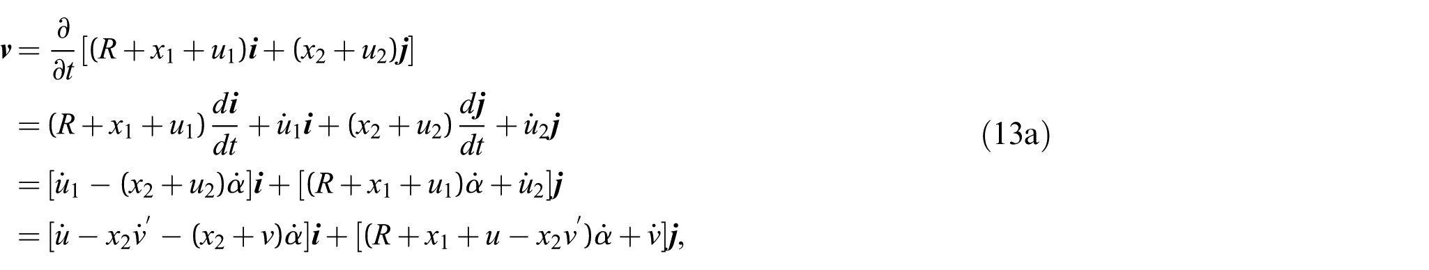
and
Similarly, the virtual displacement at a point on the beam can be expressed as

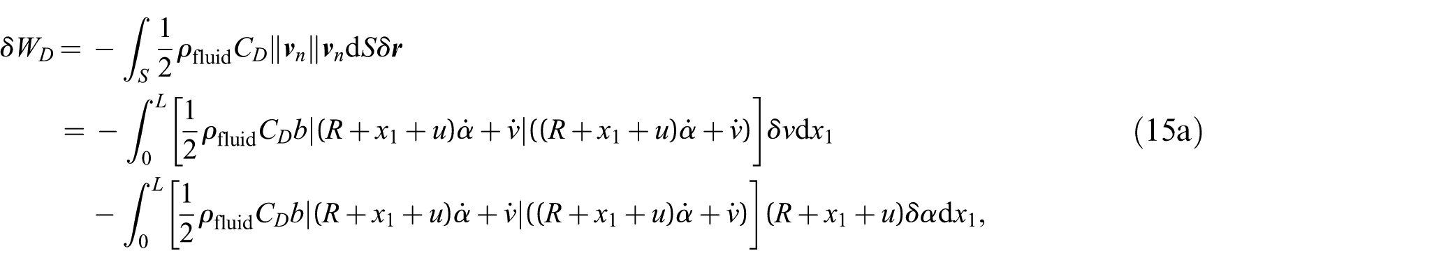
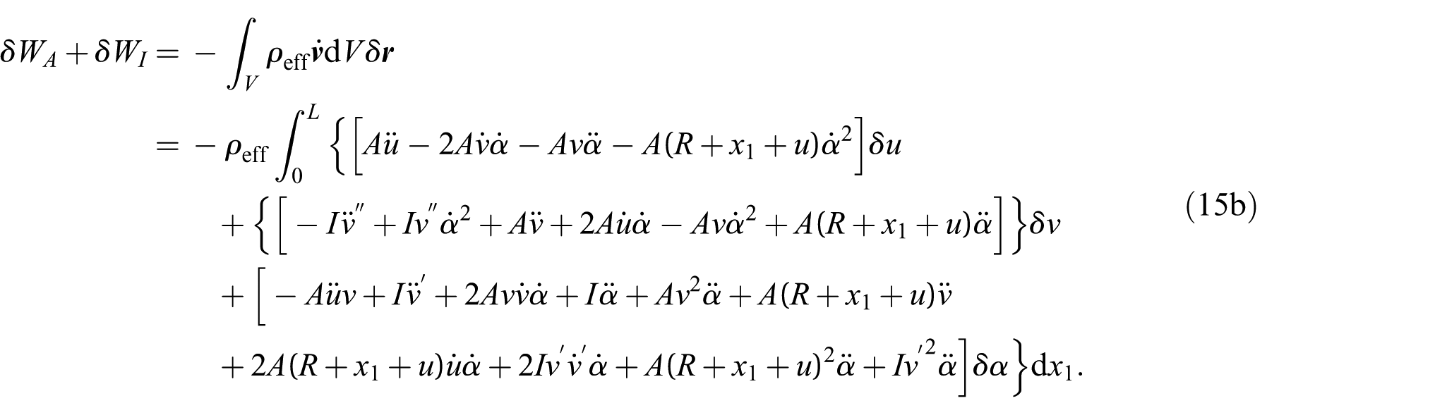
Based on equations (5), (6), (13), and (14), the virtual works associated with the drag force, the added mass force, and the inertial forces are given by
and
In addition, due to the deformation of the flexible beam, the virtual work done by the internal forces must also be considered. The relationship between the infinitesimal strain

Using the stress-strain constitutive relation, the stress

The strain energy associated with the beam deformation is then given by
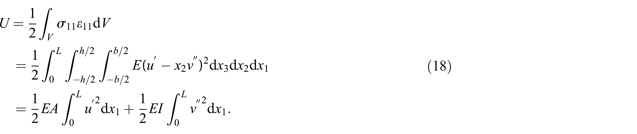
Therefore, the virtual work done by the internal forces can be expressed as follows:
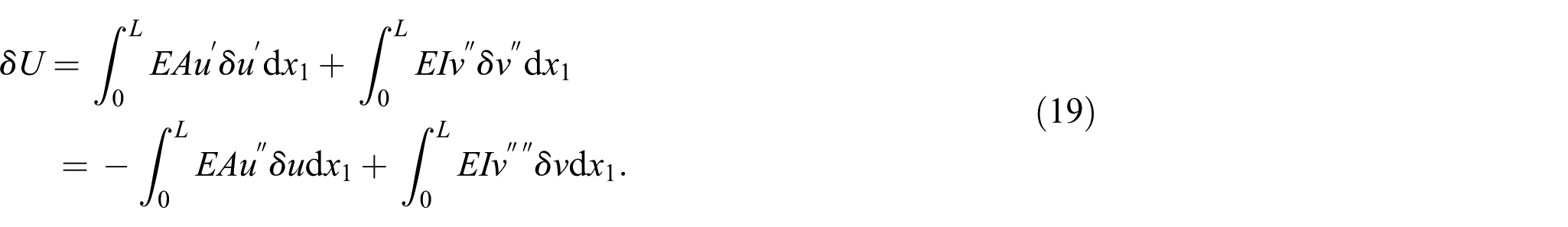
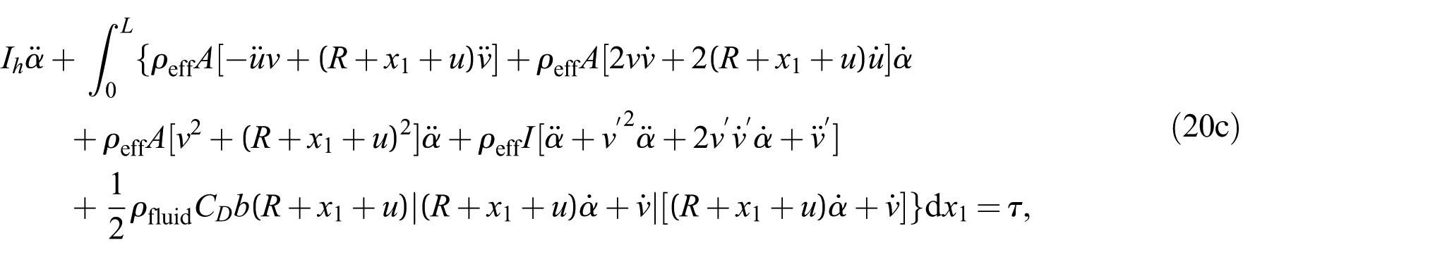
Substituting equations (15) and (19) into the principle of minimum total potential energy

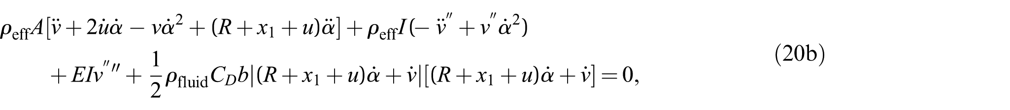
with the corresponding boundary conditions

Similar to the rigid beam model, and based on equations (2a), (5), (6), and (13), the instantaneous thrust generated by the rotational motion of the flexible beam along OX1-direction is given by
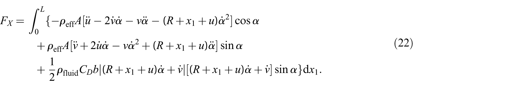
Equation (22) represents the horizontal thrust in the hub-beam system when the beam is flexible beam. We point out that when Young’s modulus E approaches infinity, the deformation (u and v) tends to zero. Then, equation (22) reduces to equation (10), which describes the horizontal thrust in the rigid hub-beam system.
3.2. Nondimensional governing equations
To account for the size effects in the solid, the governing equations of the fluid-structure interaction, as presented in equations (20) and (21), need to be nondimensionalized. This process eliminates unnecessary physical parameters and introduces dimensionless groups, making the analysis more efficient and scalable. Nondimensionalization is a widely used numerical technique for solving partial differential equations, and it is applied here to obtain the system response.
The following dimensionless parameters are used for the nondimensionalization of the governing equations
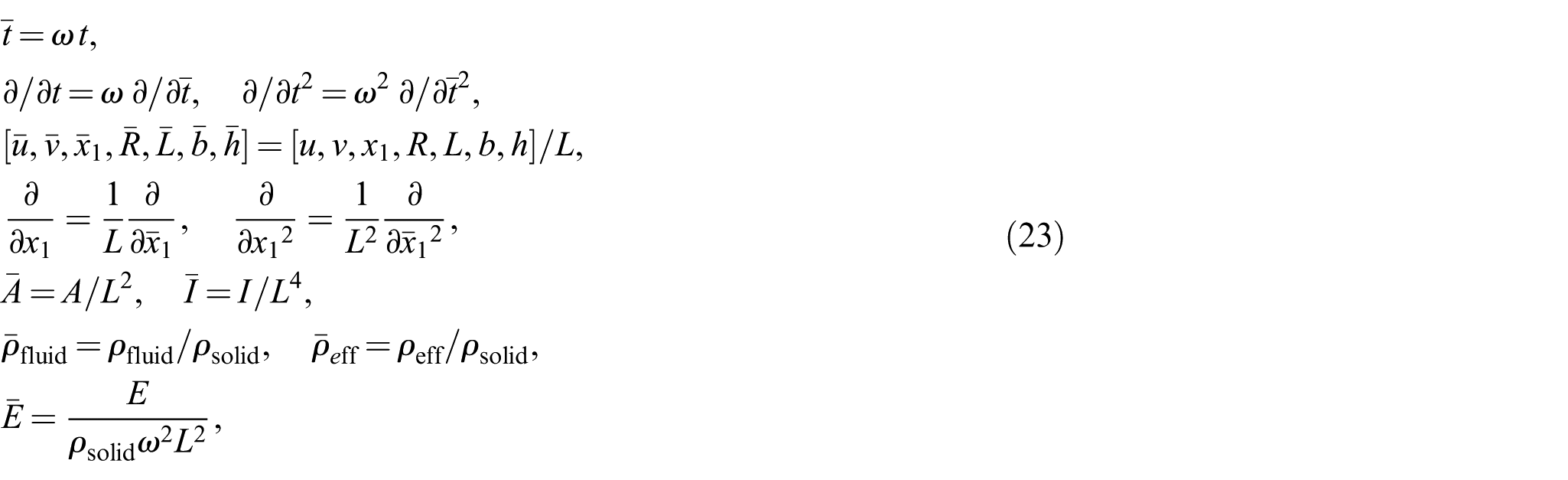
where ω is the angular frequency of the hub actuator motion, which is closely related to the variation in α.
Using these dimensionless parameters, the governing equations in equations (20a-b) and (21) are defined as follows
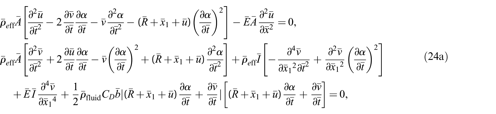
with

Subsequently, the driving torque required for the rotational motion of the beam in equation (20c) and the resulting thrust in equation (22) are expressed as follows
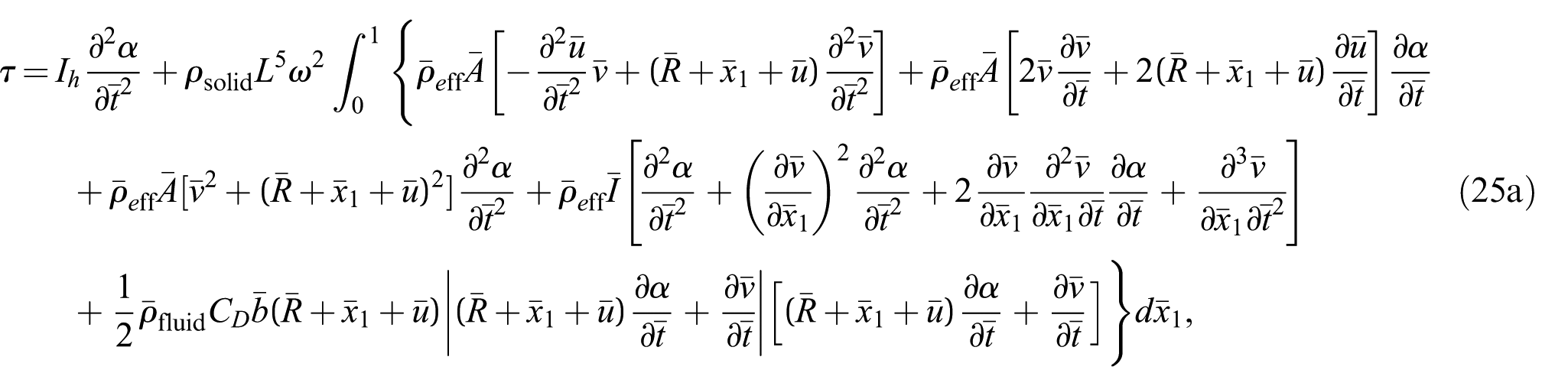
and
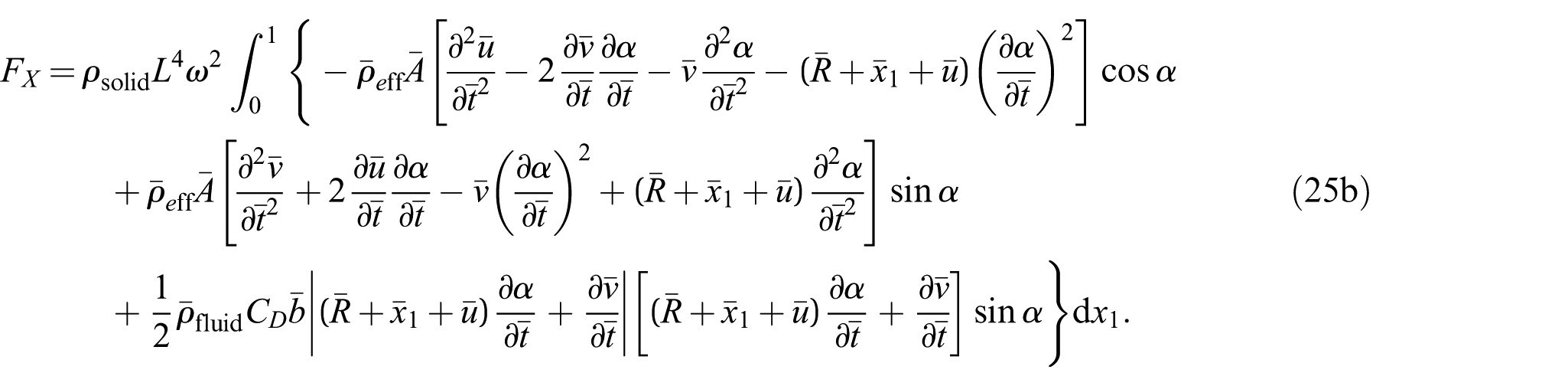
In the next section, we present both experimental and numerical results of this force and discuss the new features involved.
4. Numerical simulations and experimental validation
In this section, we first obtain the hydrodynamic coefficients based on experimental measurements. These coefficients are then utilized to validate the model introduced in the previous sections by comparing the thrust generated by the rotational beam under various operating conditions, and for both rigid and flexible models.
First, the hydrodynamic loads on the thin plate were measured using a force sensor at different flow velocities. Based on the Morison equation, the hydrodynamic coefficients C D and C A were determined. These constant coefficients were found to be 1.5499 and 0.1284, respectively.
As shown in Figure 2, the beam is mounted on a fixed hub, with an actuator used to oscillate the beam around the hub. The angle α between the OX1- and ox1-axes is related to the angular amplitude B and frequency f, which can be expressed as follows:

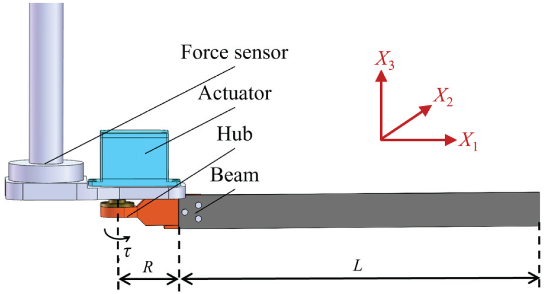
Experimental setup diagram.
In our experimentation, the beam is with a length of L = 200 mm, width b = 20 mm, height h = 2 mm, and the radius of the hub R = 40 mm. The material selected is polypropylene (PP), with a density of 910 kg/m3 and a Young’s modulus E = 890 MPa. By setting the angular amplitude B and frequency f in equation (26), and substituting it into the boundary-value problem described by equation (24), the axial displacement u and deflection v at any point on the beam and at any given time can be calculated. Subsequently, by substituting u, v, and the rotational angle α into equation (25), the torque τ required to maintain the beam’s rotation and the instantaneous thrust F X generated by the beam swing can be determined.
Figure 3 presents the instantaneous thrust curves calculated using the flexible beam model (equation (25b)) at an angular amplitude of B = π/3, and for frequencies f = 0.4 Hz, f = 0.6 Hz, and f = 0.8 Hz, along with the experimental instantaneous thrust measured by the force sensor.
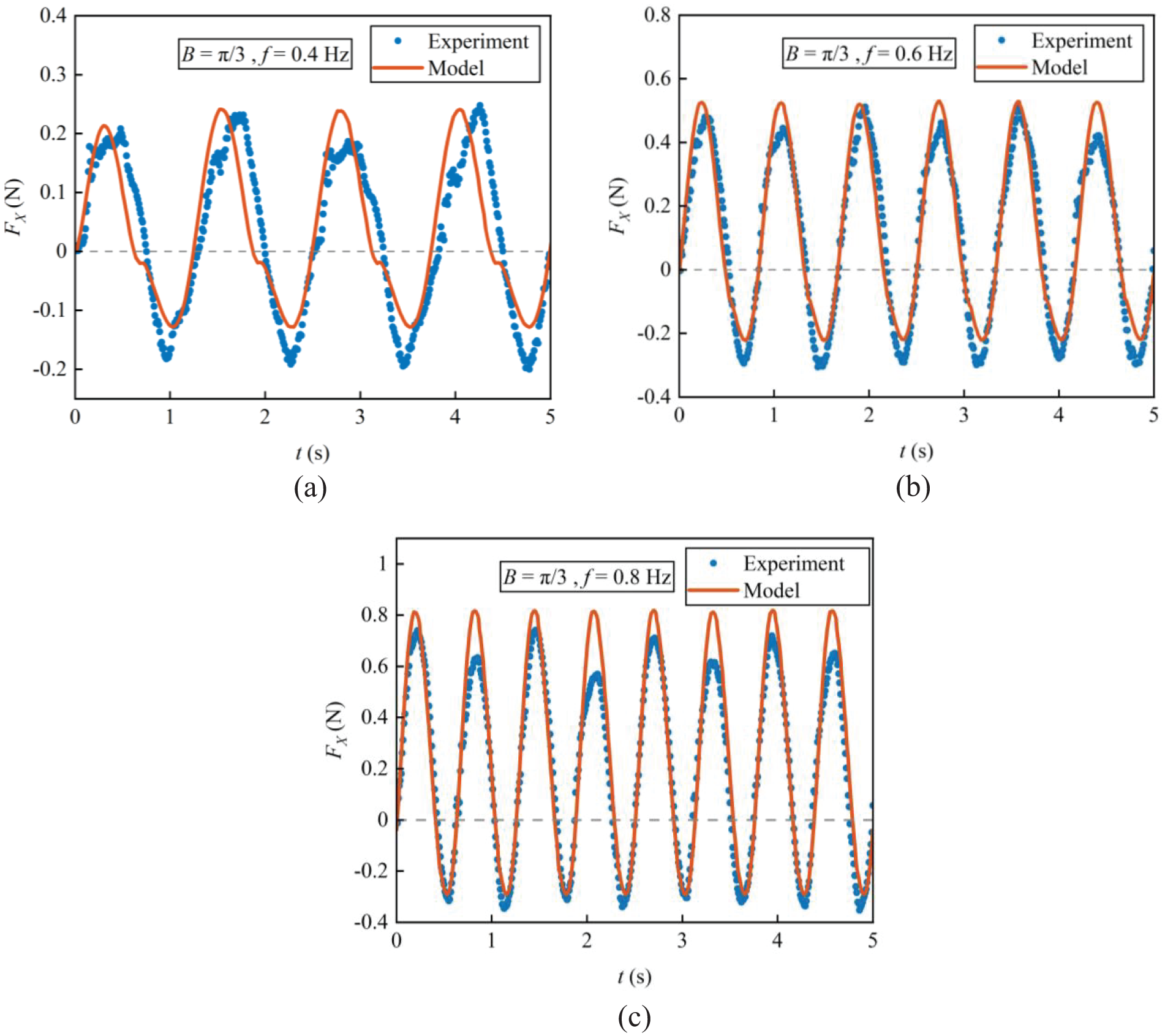
Comparison of theoretical and experimental thrust in the rotating flexible hub-beam for fixed rotation angular amplitude B = π/3; and frequencies (a) f = 0.4 Hz, (b) f = 0.6 Hz, (c) f = 0.8 Hz. The flexible beam is made of polypropylene (PP).
It can be observed from Figure 3 that the horizontal thrusts calculated and measured exhibit strong consistency. The calculated force agrees well with the experimentally measured one, although the latter one has slightly varying amplitudes due to the fact that the fluid used was not an ideal one. Figure 3 further shows that with increasing frequency (from Figure 3(a)–(c)), the thrust force gradually shifts its amplitude toward its positive side, providing an opportunity to enhance the directional thrust force for propulsion. As such, this comparison between theory and experiment indicates that the proposed rigid-flexible coupling dynamic hub-beam model, which is based on the Euler–Bernoulli beam theory and the Morison equation, is efficient in the simulation of bionic BCF propulsion. Therefore, in the next section, we study the propulsion mechanisms in BCF based on our theoretical solution.
5. Investigation of propulsion mechanisms
This section investigates the propulsion mechanisms of the hub-beam system by analyzing the thrust generated by both the rigid and flexible beam models introduced in previous sections. The analysis focuses on the effects of driving frequency, amplitude, and sectional moment of inertia on the thrust, providing a deeper understanding of how model characteristics, driving parameters, and structural properties influence the performance of the proposed hub-beam system.
We first study the effect of beam rigidity on the thrust. When the beam material approaches rigidity, the thrust calculated using the rigid model from section 2 (equation (10)) is compared with the thrust obtained using the flexible model from section 3 (equation (25b)), where the material is polyamide 66 (PA66) with a density of 1150 kg/m3 and a Young’s modulus of 8300 MPa. The other, even softer material is PP, the one used in Figure 3. This comparison aims to investigate how variations in material properties influence the propulsion mechanism, while keeping the driving parameters and other material characteristics constant.
As shown in Figure 4, the thrust curve for the rigid model, displayed over a dimensionless motion period, exhibits periodic symmetric fluctuations, indicating that the thrust is solely driven by the beam motion with no net thrust. In contrast, the thrust curve for the flexible beam model exhibits asymmetric fluctuations, with the average thrust significantly greater than zero, indicating that the beam deformation contributes additional net thrust. As the flexibility of the beam increases, the net thrust also increases, indicating a potential channel for creating more propulsion. Furthermore, the thrust curve shifts to the right, revealing a time-delay effect due to deformation. Again, it is this deformation which not only affects the beam dynamic response but also alters the interaction between the beam and the surrounding fluid, resulting in an asymmetric thrust distribution. This demonstrates that the deformation of flexible materials is the key factor in generating net thrust. Overall, within a certain range, flexible materials exhibit superior forward propulsion performance, with PP being the best among our two testing materials (PP and PA66).
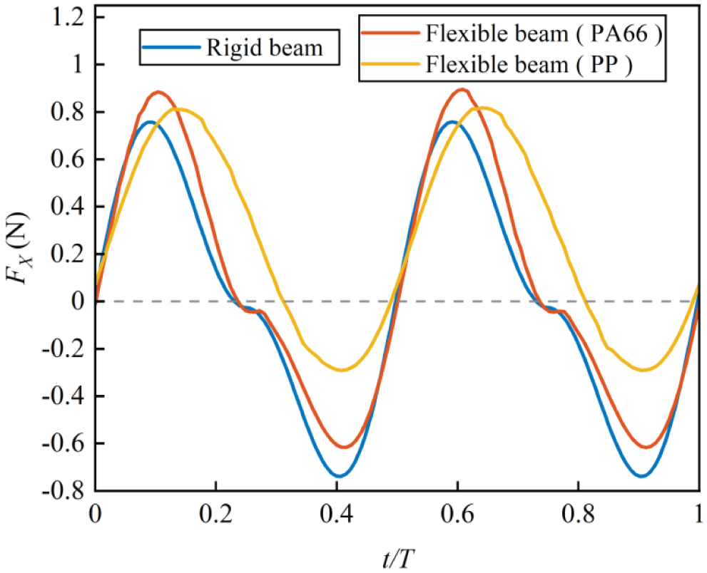
Comparison of thrust for rigid and flexible beam models at B = π/3 and f = 0.8 Hz. Note that PP is more flexible than PA66.
Second, we study the effect of the two dynamic parameters, frequency and amplitude, on the thrust, for the fixed beam material made of the soft PP. For the beam made of PP, the thrust generated at different frequencies f and amplitudes B in the flexible hub-beam system during one nondimensional vibration period is shown in Figure 5. These plots distinctly illustrate the significant dependence of thrust on both frequency and amplitude. Specifically, Figure 5(a) demonstrates that for fixed amplitude B = π/3, an increase in frequency results in a corresponding rise in net thrust. Similarly, Figure 5(b) shows that, for fixed frequency at 0.8 Hz, an increase in amplitude leads to a rise in net thrust. This clearly highlights the positive correlation between both frequency and amplitude with thrust. This behavior suggests that the deformation of the flexible beam, influenced by both frequency and amplitude, plays a key role in enhancing the thrust output.
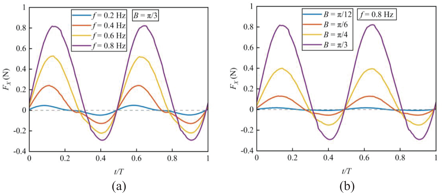
Thrust variation in the flexible hub-beam (with the soft PP beam) at different frequencies and amplitudes: (a) frequency effect for fixed B = π/3 and (b) amplitude effect for fixed f = 0.8 Hz.
Finally, we investigate the effect of the flexible beam dimensions on thrust (for the beam made of PP). The beam length is fixed at L = 200 mm, while the width b varies as 20, 30, and 40 mm. The beam height h is also adjusted to study the effect of the sectional moment of inertia on thrust generation. For ease analysis, the average thrust
Figure 6 illustrates the variation of the average thrust with respect to the beam height h for different beam width b. It can be observed that as h increases, the beam flexibility decreases, resulting in a gradual reduction in average thrust. On the other hand, thrust increases significantly with the beam width b, due to the increased flow area which can help enhance the hydrodynamic response. Notably, for different values of b, when h reaches a certain threshold, the average thrust approaches zero, indicating that the beam behaves increasingly like a rigid body. This further confirms that increasing stiffness suppresses thrust generation.
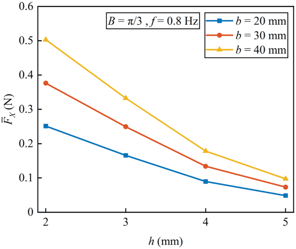
Variation of average thrust (over one motion period) with beam height for different beam widths at fixed amplitude B = π/3 and frequency f = 0.8 Hz.
Results in Figure 6 indicate that thrust variation is influenced not only by the driving frequency and amplitude but also by the geometric parameters of the beam. In general, increasing the flow area and/or decreasing the beam height could effectively enhance the thrust output of the flexible beam, offering valuable insights for the application of flexible materials in propulsion systems.
6. Conclusion
In this paper, we delve into the rotational dynamics of a rigid-flexible coupling beam subjected to hydrodynamic loads. Utilizing Euler–Bernoulli beam theory, we accurately model the elastic deformation of the beam and integrate this with the rigid displacement of the hub-beam system to accurately solve the displacement on the beam at any given time. The Morison equation is applied to find the fluid load, leading to a comprehensive model based on the principle of virtual work.
The comparison between the rigid and flexible models shows that the beam deformation is essential for generating net thrust. A more flexible beam model corresponds to a higher propulsion efficiency, with thrust results further being consistent with our experimental measurements. This validation demonstrates the accuracy and efficiency in potential future applications in bionic BCF propulsion.
As numerical examples, we show that both driving frequency and amplitude can positively influence thrust generation. Namely, an increase in the driving frequency and/or amplitude will increase the thrust value. We further show that reducing the beam height will increase its flexibility, leading to a greater thrust output under consistent swing conditions. These findings offer valuable insights for optimizing beam design and for improving propulsion performance in applications such as bionic robots.
Footnotes
Funding
The authors disclosed receipt of the following financial support for the research, authorship, and/or publication of this article: This work is supported by the National Natural Science Foundation of China (grant no. 52401391 (Y.Q.)), the Young Elite Scientists Sponsorship Program by CAST (grant no. YESS20240453 (Y.Q.)), the Ningbo Yongjiang Talent Program (grant no. 2024A-179-G (Y.Q.)), the “Innovation Yongjiang 2035” Key R&D Program (Grant No. 2024T001 (Y.Q.)), the China Postdoctoral Science Foundation (grant no. 2025T181165, No. 2023M732863 and GZC20233516 (Y.Q.)), the Open Funds of KuiYuan Laboratory (grant no. KY202436 (Y.Q.)), the Fundamental Research Funds for the Central Universities (grant no. ZDGC03 (Y.Q.)), and the Yushan Fellow Program and the National Science and Technology Council of Taiwan (grant no. NSTC 114-2221-E-A49-017 (E.P.)).
Declaration of conflicting interests
The authors declared no potential conflicts of interest with respect to the research, authorship, and/or publication of this article.