
Abstract
This paper presents the experimental and numerical analysis results of the damping properties of a bio-based sandwich with an auxetic core. The skins and core of the sandwich structure are made from the same material which is a polylactic acid reinforced with flax fibers. A 3D printing technique was used to produce the sandwich structures. Experimental tests were conducted on the skins, the auxetic structure and the sandwich beams to evaluate their damping properties. Vibration tests were performed in a clamped-free configuration. Those tests were carried out on two different configurations and four core densities of the auxetic structures in order to investigate their effect on the damping factors and dynamic stiffness. Furthermore, finite element analysis was used to validate the experimental results. The resonance frequencies and the loss factor obtained from experimental and numerical analysis were in close agreement. Finally, a study of the effect of each sandwich component on energy dissipation was carried out in order to understand the dynamic response of such beams.
Keywords
Introduction
The use of auxetic structures has grown in the past few years due to their properties such as higher stiffness, strength and great energy absorption capacity [1] as well as much lower weight when compared to conventional materials [2]. Given these attractive properties, it is typical to see these structures in a wide variety of areas including space, sports, automotive and numerous other applications. These structures are used as core materials in sandwich composites such as foams [3] and wood [4,5]. Each variation of the core material presents a number of advantages and drawbacks that must be studied depending on the application. Due to the separation of the two thin stiff skins by a core, the sandwich benefits from an increase in shear stiffness as well as the ability to absorb energy [6]. The most ordered architecture structure studied as a core configuration in sandwich panels are conventional honeycombs [7,8], lattice truss materials [9] and auxetic structures [10]. Honeycombs with zero Poisson’s ratio are also studied [11,12]. Different approaches are adopted to manufacture these complex shapes. The most effective and efficient one is the 3D printing method, also known as additive manufacturing, which ensures as much as possible the sustainability of the shape of the structure regardless of its complexity.
Auxetic structures have become the center of attention of many researchers because of their specific properties [13,14]. These structures show a synclastic curvature when subjected to out-of-plane bending [15,16]. This behavior encourages the use of auxetic structures in complex out-of-plane geometries. Later, Li and Wang [17] studied the bending behavior of a sandwich structure with truss, conventional honeycomb and re-entrant honeycomb cores. They used a 3D printing technique to produce these complex geometries. They proved that sandwiches with truss cores have the highest flexural stiffness and strength and sandwiches with re-entrant honeycomb cores enhance the energy absorption abilities. In addition, theoretical studies on reentrant honeycombs have been carried out [18] and they show that they improve the shear stiffness to weight ratio compared with conventional honeycombs.
Recently, environmental issues have derived to replace synthetic materials with bio-based counterparts. The use of bio-based composites has proven its ability to face some engineering challenges. Because of the various advantageous they offer, such as low cost, biodegradability and especially their damping properties, bio-based materials have been used by numerous industries and university laboratories [19]. The concept of using natural fibers as reinforcement of composite materials has largely been studied [10–22]. The natural fibers most investigated in the past decades are flax fibers [23,24]. They represent an eco-friendly alternative to glass fibers when used in composite structures due to their microstructure which improves their mechanical strength and stiffness [25]. In addition, flax fibers have been used in order to improve the damping properties and equivalent stiffness of composite structures made from synthetic materials [26].
This diverse research has proven that a combination of sandwich composites, auxetic structures and the use of bio-based materials, especially bio-composites reinforced with flax fibers, can constitute a material with high mechanical and damping properties. The main idea of this work is to take advantage of the high dissipative properties of auxetic materials and the high damping characteristics of flax fibers by the use of biological material and the specific performances of sandwich composites. In this context, a bio-based composite with an auxetic core was manufactured and its damping properties were tested. The damping properties of the skins, core and sandwich structures were determined using experimental vibration tests and numerical simulations based on the strain energy model method. This paper contains four sections. First, sandwich beams are designed using CAD software and made using a 3D printing technique. Then, the damping behavior of the sandwich and its components are investigated using flexural vibration tests. Then, a numerical model is developed and the effect of the auxetic configuration as well as the core density on the dynamic properties is measured and discussed. Finally, a numerical model is used to evaluate the contribution of the skins and the auxetic structure in the total dissipated energy of the different sandwich configurations.
Experimental analysis
Materials and manufacturing
The material used in this study is a tape of polylactic acid (PLA) 1.75 mm in diameter reinforced with flax fiber filament furnished by a NANOVIA, from Louargat France. It is manufactured from a bio-based, biodegradable and renewable material. It is dedicated to additive manufacturing techniques. The 3D printing used here is the MakerBot Replicator2 Desktop. Figure 1 presents the design of the printing process. It consists of an extrusion head, filament rolls, building platform and X-Y motion mechanism. By following some parameters proposed by the company, the extrusion temperature is set to be equal to 210°C with a travel speed of 100 mm/s and the building platform temperature is equal to 55°C. The specimens were designed with CAD software and then translated into instructions compatible with the MakerBot Replicator2 Desktop to be printed. The printing orientation was considered and selected in a way that improves the mechanical properties of the sandwich. As a consequence, the same orientation was adopted to print all specimens.
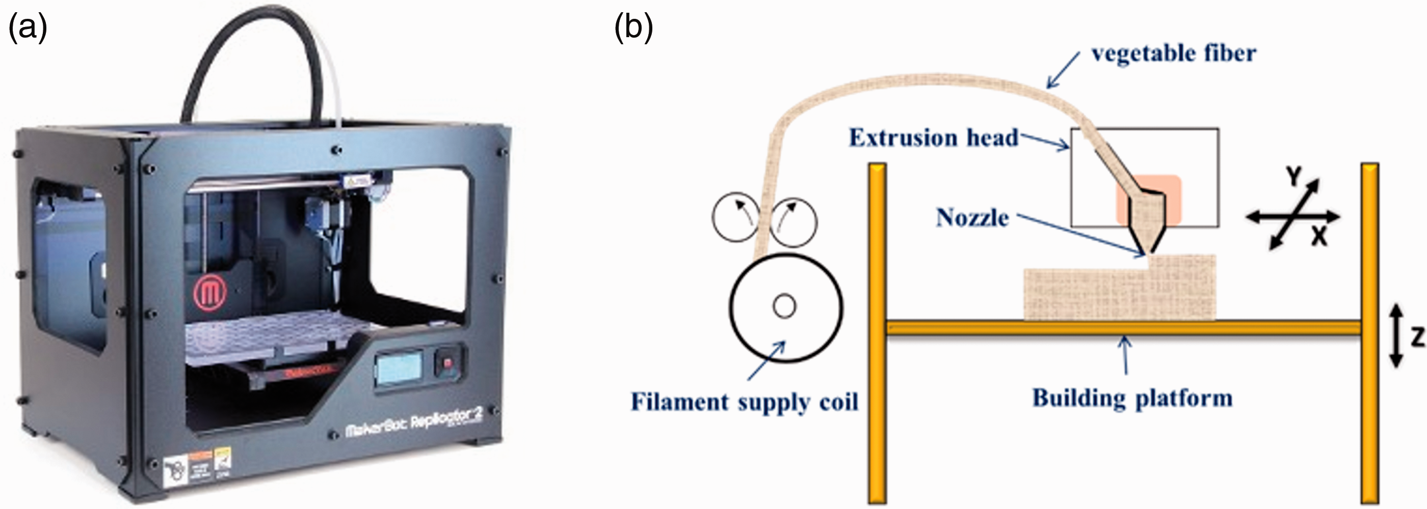
(a) MakerBot Replicator2 and (b) the design of the 3D printing process.
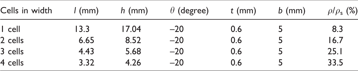
The sandwich studied is made up of two skins and a re-entrant honeycomb core. The geometry of the auxetic core is given in Figure 2. l is the original length of the inclined cell walls and h is the length of the vertical ones. θ is the initial angle between the inclined walls and the X axis. t is the cell wall thickness. The thickness of the auxetic structure is 5 mm. The width of the specimens is set to be equal to 25 mm. It is discretized to one, two, three and four unit cells. Each number of cells along the width gives a specific density to the core. From Figure 2(c), H = 2(h + lsinθ) and L = 2lcosθ are the specimen length on X and Y axes, respectively. Two different configurations are tested in which the unit cells switched orientation (W-configuration and L-configuration), as shown in Figure 2(a) and (b). In addition, different densities are used to produce diverse sandwich configurations. The relative density [17] of the auxetic core is calculated by
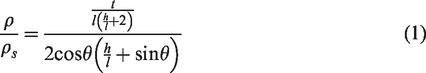
Top and side views (a and b) of the different configuration of the auxetic structures and (c) the design of the unit cell used.
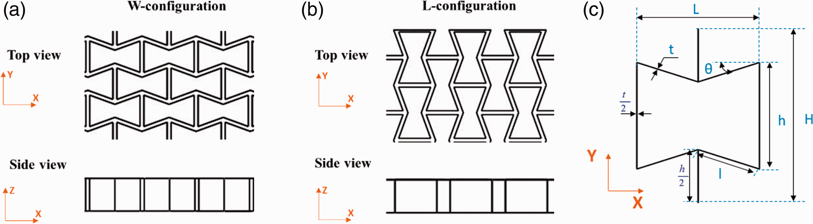
The dimensions of the unit cell used in the core and relative densities of each configuration are given in Table 1. The material properties are measured using uniaxial tensile testing performed on 3D printed dogbone following the ASTM D638 standard. The values obtained are shown in Table 2. Several configurations of the sandwich beam are prepared. The sandwich is set to be equal to 25 mm wide and the thickness is equal to 7 mm (2 mm for the two skins and 5 mm for the core). The free length of the specimens tested was equal to 170, 200 or 230 mm. A bloc 40 mm in length was printed with each specimen to avoid damaging the auxetic core while clamping the beams.
Design parameters of the auxetic core.
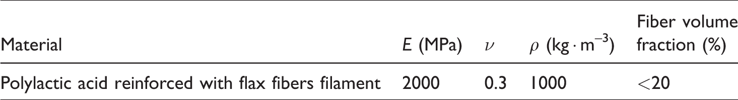
Engineering constants of polylactic acid reinforced with flax fibers.
Experimental process
The damping characteristics of the sandwich structure and their components (skins and auxetic core) are evaluated. Specimens are supported horizontally in a clamped-free configuration as shown in Figure 3. The length of the clamped end is set to 40 mm. The flexural vibration of the beams is produced using an impact hammer (PCB084A14) near the clamped end. A laser vibrometer (OFV 303 Sensor Head) is used to detect the displacement of the beam near the free end. The signals generated by the excitation and the response are processed using an acquisition card system and analyzed using the NVGate software. For each beam, the flexural vibration tests are executed for different free lengths varying between 170, 200 and 230 mm in order to obtain various peak frequencies.
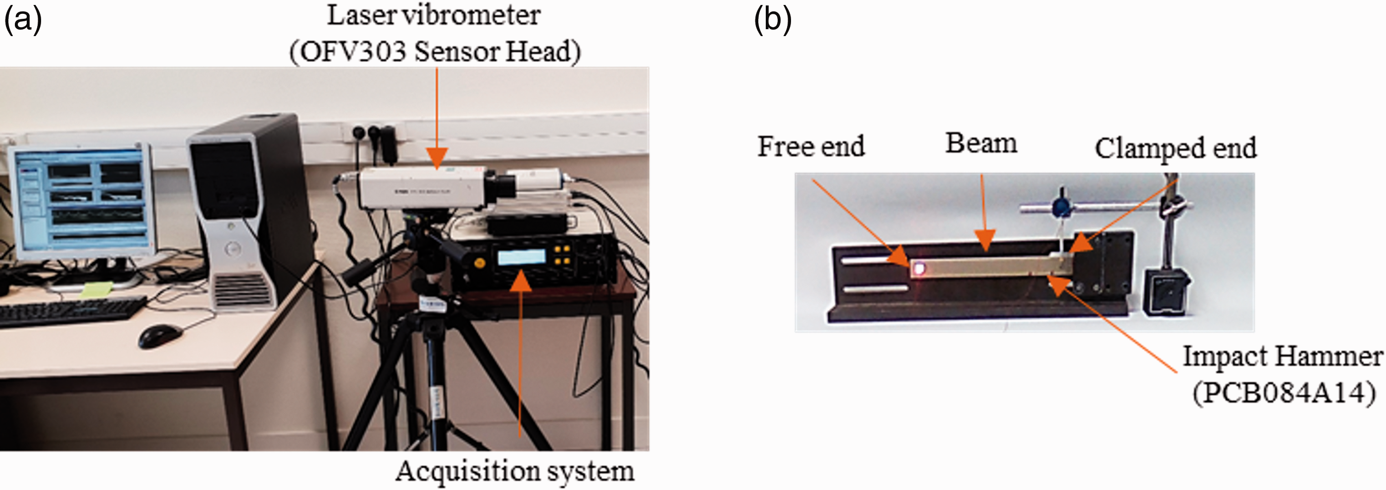
Experimental equipment for clamped-free vibration tests: (a) experimental set up and (b) embedded specimen.
Different technique can be used to characterize the dynamic properties of the material such as the dynamic mechanical analysis method [27,28] and the experimental Frequency Response Functions (FRF) [4,29]. In the present work, the FRF method is used to determine the natural flexural frequencies (Figure 4(a)). This method is widely used because of its efficiency in evaluating the loss factor. The half power bandwidth (HPB) method is used to calculate the modal damping factor, Figure 4(b). It is calculated using equation (2). The loss factor ƞ
i
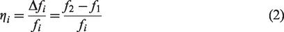
is defined as the ratio between the bandwidth frequencies (Δfi) at which the amplitude resonance decreases by 3 dB, divided by the resonance frequency (fi)
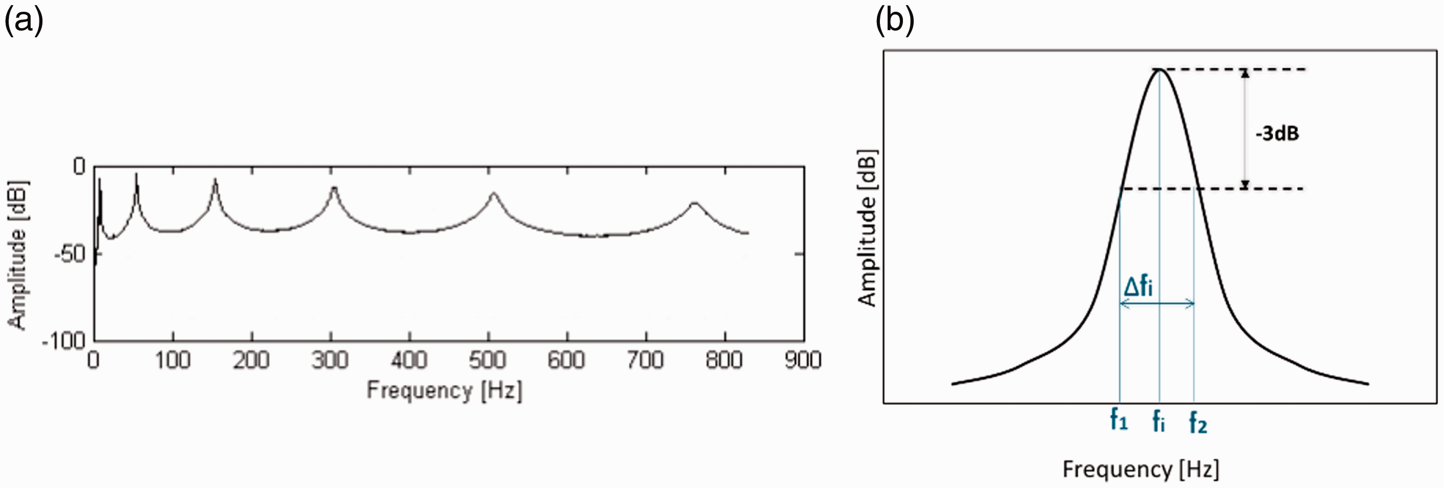
(a) Typical frequency response to an impulse excitation and (b) half power bandwidth method.
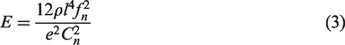
Young’s modulus E of composite skins for every flexural mode is calculated by [4,30]
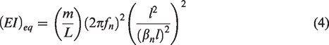
Furthermore, the equivalent stiffness of a sandwich beam for every flexural mode can be calculated by [31]
Vibration behavior of the sandwich components
Composite skins
The evolution of the dynamic properties of the skin as a function of frequency is studied and presented in Figure 5. The results show that the loss factor and Young’s modulus increase when the frequency increases. The average increase of the damping coefficient and Young’s modulus is about 50% and 13%, respectively, in the frequency range studied. In addition, it can be observed that the stiffness at low frequency is close to the quasi-static Young’s modulus presented in Table 2.
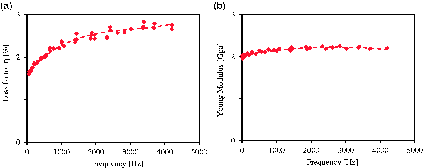
Evolution of dynamic properties with the frequency of the skins: (a) loss factor and (b) Young’s modulus: experimental and adjusted curve.
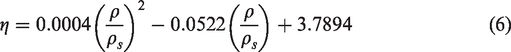
The evolution of the loss factor of the skins as a function of the frequency is expressed by a second-degree polynomial equation

Re-entrant honeycomb structure
The vibration behavior of the re-entrant honeycomb structure is studied. Figure 6 presents the experimental results of the loss factor of auxetic structure with different relative densities in L-configuration at 1000 Hz. The loss factor decreases with the increase in the auxetic structure’s relative density. This is as expected because the increase in the relative density in the structure enhances its stiffness and therefore reduces the damping properties. When the relative density of the auxetic structure increases from 8.3% to 33.5%, the loss factor decreases by about 30%. The variation in the loss factor of the re-entrant honeycomb structure as a function of the relative density can be expressed by
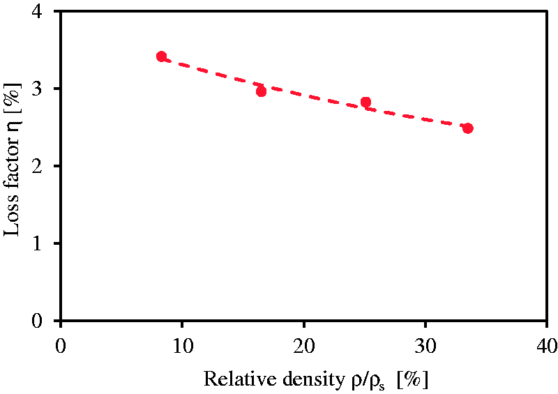
Evolution of the loss factor with the relative densities of the auxetic structure.
Moreover, a comparison between the dynamic properties of the L-configuration and the W-configuration is conducted. The relative density of the auxetic structure is set to be equal to 25.1%. Figure 7 shows the variation in the damping coefficient as a function of frequency. For a frequency range from 0 Hz to 1500 Hz, the L-configuration presents a damping factor greater than that of the W-configuration. Above this frequency, the damping property of the W-configuration exhibits a rough increase up to 5.5% at 2800 Hz, while those of L-configuration gradually increases up to 3.5%. This result can be explained by comparing the connection between the unit cells for the two configurations. In fact, as seen in Figure 2, it is clearly observed that the connection between the unit cells for the W-configuration is made by the vertical cell wall so the unit cells are united. On the other hand, the unit cells in the L-configuration are separated and the connection in the X-direction, which is the direction of the free flexural vibration, is made by a free wall. As a consequence, the connection between unit cells in W-configuration is more rigid which leads to a stiffer structure.
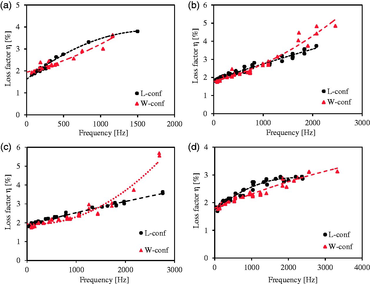
Evolution of the loss factor with frequency of the L- and W-configurations for different relative auxetic densities: (a) 8.3%, (b) 16.7%, (c) 25.1% and (d) 33.5%.
Vibration behavior of the sandwich structure
The dynamic properties of sandwich beams with an auxetic core for the L-configuration with different densities at 2000 Hz are studied. The damping coefficient of these beams is determined using the experimental setup described previously. The results are presented in Figure 8. It appears clearly that the loss factor of the sandwich composite is not highly dependent on the relative density of the auxetic core. However, the equivalent stiffness depends on the relative core density. An increase in the relative core density from 8.3% to 33.5% generates an increase in the equivalent stiffness of about 58%. In fact, when the relative core density of the sandwich beams increases, the quantity of the material used to print the sandwich increases and therefore the beam becomes stiffer. Different studies are done to calculate the equivalent stiffness of sandwich structures [17,34] using bending tests. The equation used in these studies combines the parameters of the auxetic geometry as well as the parameters of the material studied. According to the results found in this work, it was possible to express the equivalent stiffness as a function of the auxetic core’s relative density. At a frequency of 2000 Hz, the equation that links the equivalent stiffness with the relative core density is

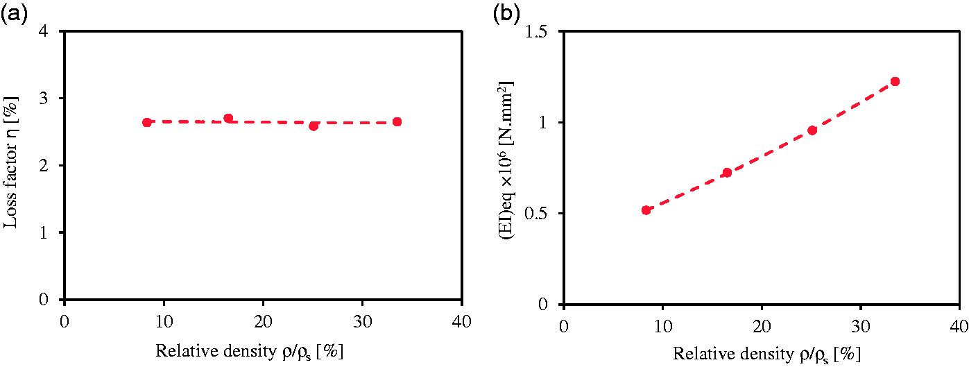
Evolution of dynamic properties with relative core density of the sandwich structure: (a) loss factor and (b) equivalent stiffness.
In addition, the configuration’s effect on the dynamic properties of the sandwich structure is tested (Figure 9). Results show that the damping factor of the sandwich beams is not extremely dependent on the configuration. In fact, the loss factor of the sandwich with an auxetic core in the L-configuration is 6% greater than that in the W-configuration in the sandwich with 16.7% relative core density. Then, the effect of the configuration on the equivalent stiffness is measured. It is shown that the sandwich beams with re-entrant honeycomb core in the W-configuration are stiffer than those in the L-configuration. This decreases as the frequency increases. For the sandwich with 16.7% relative core density, the equivalent stiffness decreases by 65% and 34.5% for the sandwich structure with an auxetic core in the L-configuration and the W-configuration, respectively, in the frequency range from 0 Hz to 4000 Hz.
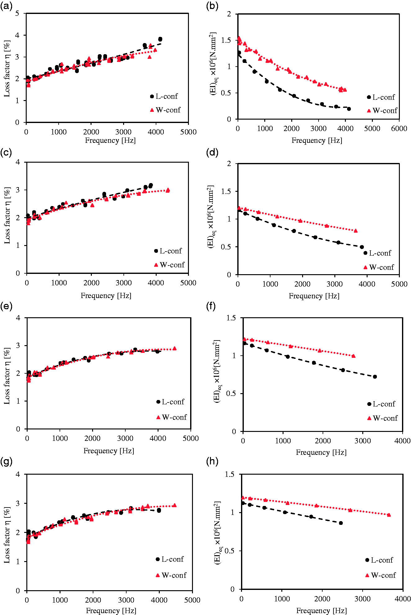
Evolution of dynamic properties with frequency of: the loss factor of the sandwich with relative core density (a) 8.3%, (c) 16.7%, (e) 25.1% and (g) 33.5%; and the equivalent stiffness of the sandwich with relative core density (b) 8.3%, (d) 16.7%, (f) 25.1% and (h) 33.5%.
Numerical validations
Different studies have been developed to evaluate the damping factor of sandwich structures numerically. The first work on the determination of the loss factor of a composite structure was developed by Ungar and Kewin [35]. Then Adams and Bacon [36] introduced the model strain energy method which was used later by Monti et al. [4], Daoud et al. [29] and Assarar et al. [37]. This method considers the total and dissipated energy in the composite and then uses them to calculate the loss factor. First, the resonance frequencies, stress and strain tensors must be calculated for each flexural mode. Then, the total strain energy and the dissipated energy are calculated, which are used to determine the global damping factor of the sandwich structure.
Presentation of the numerical model
The finite element analysis method is used to calculate the natural flexural frequencies and then determine the damping factor of the sandwich beams. Numerical simulations are performed using the MSC Nastran finite element software. The sandwiches and their components are studied under clamped free configuration as shown in Figure 10(a). The constitutive material of the sandwich structure is assumed to have linear elastic behavior. Table 2 presents the material properties used in the simulations, which correspond to the 3D printed material. The nonlinearity of the sandwich structure is defined by the geometry of the auxetic structure itself imported into the software. The structure is meshed using tetrahedral linear elements. The number of nodes used to mesh the sandwich structure depends on the core densities and the configuration used. The number of nodes used to mesh the sandwich was set in an interval from 13,648 (for 8.3% relative density) to 21,241 (for 33.5% relative density). Figure 10(b) presents the meshing of the model. The width of the beams tested is set to 25 mm, the lengths were 170, 200 and 230 mm and the thickness of the whole sandwich was 7 mm.
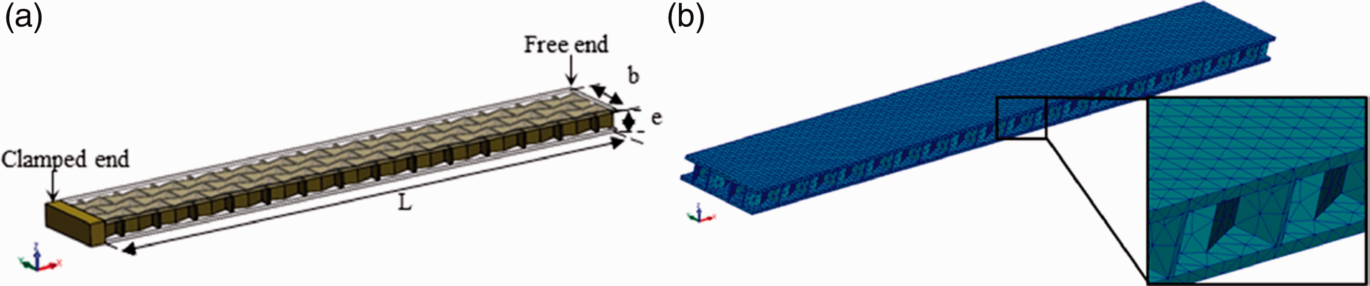
(a) Schematic illustration of the sandwich structure with a boundary condition and (b) meshed sandwich.
Using the Lanczos solver on MSC Nastran [38], the resonance frequencies of the sandwich beams can be calculated by solving the real eigenvalue problem expressed by

Determining the global loss factor
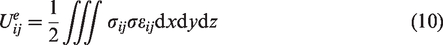
When the resonance frequencies are calculated, each mode is considered individually. The stress and the strain tensors are determined and analyzed to calculate the elastic energy of the sandwich (s) and its components (face f and core c). The total elastic energy of a finite element e is calculated in x, y and z directions by

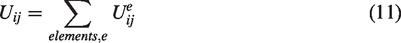
Then, the total strain energy of each component is evaluated in all directions by summing the energies of all elements constituting the sandwich and their components
To simplify the calculation of the numerical damping, it is necessary to determine the directions which support the majority of the elastic energy. Figure 11 represents the evolution of the fraction of the elastic energy by the total elastic energy stored in the sandwich structure as a function of frequency for different directions. The configuration tested here is the one with the core relative density of 8.3% in the L-configuration. The results are obtained using the numerical model described previously. It can be clearly observed that the energy in xx and zx directions presents the major part of the sandwich’s elastic energy compared to those in the other directions.
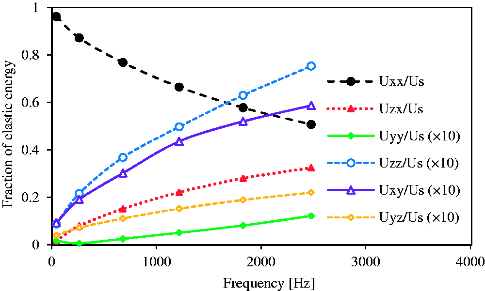
Fraction of the elastic energy in the different directions.
According to the preceding results, it would be possible to consider only the longitudinal energy and the transverse shear energy stored in the faces, auxetic cores and the whole sandwich. Indeed, the damping and shear modulus were deduced from experimental flexural vibration and the vibration beam technique (VBT) ASTM E756e98 method, respectively. Then, correlating these results with those deduced from the finite element analysis, the numerical loss factor can be calculated.
In this case, the total elastic energy of a finite element e becomes

And the total strain energy U accumulated in the sandwich structure and their components is calculated by

Then, the dissipated energy by the sandwich components is given as a function of the strain energies of the elements and the specific damping loss factor

The total energy dissipated ΔUd in the structure is calculated by summing those of each element
The quantity of energy dissipated by the sandwich structure is the sum of the energy dissipated in the faces and in the core

Finally, the global loss factor, for each flexural mode, can be calculated by dividing the total energy dissipated ΔUd by the total strain energy U
Discussion
Analysis of the damping of sandwich structures
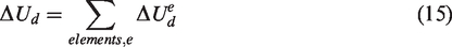
The experimental results are validated numerically. Thus, the evolution of the damping factor as a function of frequency for the four densities in L-configuration is presented in Figure 12. For each sandwich beam, finite element results are correlated to those measured experimentally. There is some difference between the experimental and numerical natural frequencies. Specimens are produced using 3D printing technology which can produce some variability in the sandwich structure. In addition, the clamping conditions in the vibration tests affect the measured natural flexural frequency and the damping coefficient of each sandwich structure. In addition, finite element analysis considers the material as quasi-homogeneous. As a consequence, experimental and numerical results are not exactly identical.
Evolution of sandwich loss factors with frequency for the L-configuration, comparison between experimental and numerical results for different relative core densities: (a) 8.3%, (b) 16.7%, (c) 25.1% and (d) 33.5%.
Analysis of the energy dissipated in the sandwiches and their components
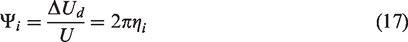
The energy dissipated by the auxetic core and the skins is evaluated for every core relative density in the L-configuration and for L- and W-configurations with 16.7% relative core density. Results are presented in Figures 13 and 14. The results are obtained from finite element modeling. For each sandwich configuration tested, it is clearly observed that the energy dissipated by the skins is higher than that dissipated by the auxetic core for the lowest frequencies. Then, we observe an increase in the energy dissipated by the core and a decrease in that dissipated by the skins as a function of frequency. Figure 13 shows that the energy dissipated by the core increases with density. When the relative core density increases, the core becomes stiffer, more resistant and subject to shear loading. Likewise, the energy dissipated by the core in the W-configuration is higher than that dissipated in the L-configuration (the W-configuration is stiffer than the L-configuration). Furthermore, the fraction of energy dissipated by the auxetic core and the skin is similar, equal to 50%. It is also noticed that the frequency at which the fraction of the energy dissipated by the re-entrant honeycomb core and that dissipated by the skins is equal and increases as the core density decreases. Using these results and adopting a parametric analysis, it is possible to find the optimal parameters of the auxetic structure in order to optimize the mass damping ratio for a given frequency. It can be concluded that sandwich in the W-configuration with low density enhances the damping coefficient.
Fraction of energy dissipated by the core and skins in the L-configuration for different relative core densities.
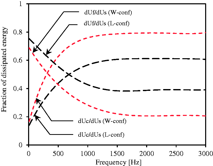
Fraction of dissipated energy by the core and skins in the L and the W-configurations.
Conclusion
The evaluation of the dynamic characteristics of a bio-based sandwich composites with an auxetic core based on experimental analysis and numerical simulations is presented. The sandwiches and their components are produced from the same bio-based materials which is a tape of PLA reinforced with flax fibers (<20%). It was designed using CAD software and produced using 3D printing technology. Several dynamic tests were performed on different core densities (4) and configurations (2) to determine the damping properties of the sandwich structures.
The experimental study was carried out to investigate the natural frequencies and damping factor using an impulse technique. Using the HPB method (–3dB), the dynamic properties of the skins and the core were studied. Then, the damping properties of the whole sandwich were studied as well.
Moreover, a numerical model using MSC Nastran software was developed. The model strain energy method was used to determine the natural flexural frequencies and modal damping factors of the different sandwich configurations. The results derived from experimental analysis present close agreement with those from numerical simulation. In addition, the contribution of the core and skins in the damping response of the whole sandwich was investigated.
First, the loss factor and the stiffness of the skins and the different core configurations are measured. The results show that both the stiffness and the loss factor increase with frequency. In addition, an increase in the density of the auxetic structure leads to a decrease in the loss factor. Then, finite element analysis is used to determine the contribution of each direction to the total energy dissipated by the sandwich. The results show that the damping coefficient and the equivalent stiffness of the sandwich beams depend on the core densities and on the configuration of the auxetic core used. In addition, the numerical model allows us to determine the characteristic factors that have the greatest influence on the damping factors of the sandwich structures. At the lowest frequency, the skins dissipated the major part of the energy. On the other hand, at high frequency, the damping depended on the energy dissipated by the auxetic core. From the different results found in this study, it can be concluded that specimens in the W-configuration with the lowest core density enhance the dynamic properties of the sandwich. Considering the numerical model, a parametric study can be developed to improve the damping properties of sandwich structures. The influence of the faces and the auxetic core thickness can be investigated. In addition, the influence of the parameters of the unit cell of the auxetic structures on the damping properties can be investigated.
Footnotes
Declaration of Conflicting Interests
The author(s) declared no potential conflicts of interest with respect to the research, authorship, and/or publication of this article.
Funding
The author(s) received no financial support for the research, authorship, and/or publication of this article.