






Abstract
This research work aims to experimentally study the quasi-static mechanical behavior of a new proposed sandwich insulated panel consisting of autoclaved aerated concrete as the core material and composite laminate as the face reinforcement. Composite insulated sandwich panels were fabricated using woven E/glass fiber plies and metal sheet as face skins stacked to the core. Quasi-static flexural three-point bending and indentation tests were carried out to investigate the mechanical responses of the manufactured sandwich panels. Stress distribution and crack growth of the reinforced beam elements in flexural tests were captured and tracked through a digital image correlation method. The effects of several parameters such as the indenter’s diameter, nose shape geometry and face sheet stacking sequence on the energy absorption behavior of specimens with different boundary conditions based on visual observation of captured microscopic images were explored and compared. Test results indicated that both indenter diameter and boundary conditions affect response and damage mechanisms significantly whereas indenter nose shape has a slight effect on energy absorption. The results illustrate the benefit of incorporation of fiber metal laminate face sheets as a simple and cost-effective in situ technique to strengthening the existing lightweight cementitious materials used in the construction of non-structural components.
Keywords
Introduction
Lightweight core composite sandwich materials are widely researched topic due to their sustainability and durability. Utilizing such cost-effective materials with low embodied energy has become a significantly vital approach in pre-cast modular construction techniques. Sandwich composite panels offer excellent strength-to-weight ratio, manufacturing efficiency and are ideal for precast panels as well as reinforcement. Structural insulated panels (SIPs) is a concept in the composite industry whose panels with cellular lightweight core located between composite face skins are widely used in aerospace, aviation, and ship industries despite the fact that they are relatively new civil engineering materials [1].The use of “cellular materials” concepts as core in composite sandwich structures is rapidly grown in importance [2]. Most recent studies on sandwich structures focused on a lightweight core made of honeycomb, corrugated, lattice, and cellular metal and polymer foams [3,4]. However, the potential usage of lightweight cementitious materials in the structural application could be an interesting choice for structural components [5–7]. The life cycle analysis of construction materials generally includes considerations such as energy consumption in production, transportation, construction, and life span and/or recycling after use [8]. Based on the comparative evaluation of the embodied energy data in the literature as shown in Figure 1, it is apparent that autoclaved aerated concrete (AAC) is a viable alternative to similar construction materials such as blocks, bricks, or lightweight panels [9] and provides great promise in applications as a core material in composite sandwich structures. AAC is a type of lightweight cellular cementitious material composed of cement mortar and air voids. Because of its low density and strength characteristics, it would be an ideal option for core material to be used in composite sandwich structures [10]. The capacity of such materials in structural applications has not been fully investigated. Recently, some investigations have been carried out on reinforced sandwich panels with hollow, lattice and cellular core materials under quasi-static and impact loadings both experimentally and numerically [11–14]. Composite sandwich panels have been developed with AAC masonry blocks covered with textiles to withstand blast and impact loading. These ideas proved their capacity to withstand lateral loading. A.V. Oskouei studied the effectiveness on the structural behavior of AAC blocks by reinforcing specimens with fiber-reinforced polymer (FRP) sheets (glass and carbon). Their test result showed that the application of FRP at both faces of samples increases the load and deflection capacities [15]. V. Dey et al. investigated the mechanical response of textile-reinforced aerated concrete sandwich panels using an instrumented three-point bending under static and low-velocity dynamic loading. They used two types of AACs including plain and fiber reinforced concrete as core material consisting of alkali resistant glass textiles as cementitious binder [16]. Uddin et al. studied the flexural behavior of composite panels made with AAC core and carbon fiber reinforced polymer face sheets. They concluded that the flexural strength of panels enhanced significantly in comparison with plain AAC panels [17].

Energy consumption of some construction materials by volume [9].
Z.O. Pehlivanli et al. experimentally studied the effects of various fibers on thermal and mechanical properties of two different class of AAC material. They found that carbon fibers give the highest compression and flexural strength. The resistance of the exterior AAC masonry walls was enhanced by applying different reinforcing fabrics [12]. As a result, a sensible understanding of indentation and low-velocity impact response of both foam cores and sandwich insulated AAC panels is necessary to predict and assess their consequent damages [18]. Hybrid reinforced composite sandwich panels, which consist of a combination of different face sheets, are one of the solutions to the insufficient stiffness and reinforcement of lightweight core materials such as AAC [19]. An interesting possibility is to combine the latest generation of fiber–metal laminates (FMLs) to the faces of AAC panels to take advantages from both fibers and metal sheets. FMLs are stacked components based on alternating layers of aluminum alloy and thermosetting composites [20,21]. The concept usually applied to aluminum with aramid (ARALL) and glass fibers (GLARE), but also can be applied to other constituents [22]. Studies on the incorporation of such composite materials in the upgrading of cellular cement-based materials have been very scanty and focused on the flexural or shear strengthening of beams under monotonic loading and on aspects of the bond between the cement-based core and textile composite face sheets [23]. To investigate the validity of the bonding of FRP, Hong Zhu et al. studied the bond-slip relationship between FRP sheets and concrete substrate through DIC measurement [24]. Actually to monitor the displacements and crack inspection it is a useful device.
Moreover, the capacity of AAC as core material to fabricate SIPs acquires more experimental investigations. Such materials may encounter a wider range of chemical and mechanical (quasi-static and dynamic) contact damage. This research is motivated by the lack of knowledge in the study of fiber metal reinforced composite sandwich panels with AAC core for structural applications. The category motivated the authors to propose the concept of applying composite face sheets to AAC blocks approaching efficiency in structural and load-bearing applications as well as a reinforcing element. Fiber-reinforced composites are currently being used to repair or strengthen reinforced concrete bridges and other structures. Therefore, it is proposed herein that because AAC is ultra-lightweight in nature and FML is so stiff and has high specific strength (that is, strength divided by weight per unit volume), the two could be used together to form hybrid panels as a structural component.
In order to demonstrate the energy absorption capability of the proposed SIP, experiments of different face skin configurations were fabricated using woven E/Glass and FML sheets. The response of reinforced AAC blocks with proposed face skins under quasi-static flexural three-point bending and indentation tests were studied and evaluated. The flexural response of experiments was tracked through a digital image correlation (DIC) technic description to capture the full-field deformation and crack growth of specimens during the loading process. The quasi-static indentation was also implied and some geometrical effects of indenter were inspected. Failure mechanisms, as well as crack propagation of different sample configurations, also were identified and analyzed.
Physio-mechanical characterization of AAC
Based on ACI 523.2R, aerated concrete is manufactured from a mixture of Portland cement, different sources of silica, quick lime, gypsum, water, and aluminum powder or paste [25]. This mixture, if autoclaved for accelerated strength development, is called as autoclaved aerated concrete.
Aerated concrete could be classified based on its dry density of 400–800 kg/m3 and compressive strength values of 2–6 MPa [26]. Table 1 presents the AAC ingredients as received from the manufacturer (Parin beton) indicating that dry density is in the range of the mentioned ASTM specification.
Proportion of the AAC ingredients.

Neithalath et al. reported that approximately 80% of the volume of the hardened material is made up of pores with a general ratio of 2.5:1.0 air-pores to micro-pore [27]. The porous microstructure is a result of a chemical reaction between calcium hydroxide and aluminum powder. To characterize the pore distribution of AAC material, through a microscopically study, image analysis has been successfully employed using field emission scanning electron microscopy (FESEM). Magnification of 56× was selected with a pixel representing 16 μm and each image covering 43.5 mm2, its porous structure, identified with micro air-pores to macro air-pores with the pore diameter in the range of 0.1 to 1 mm. Figure 2 shows the AAC blocks and its typical pore structure topology obtained by gray-scale image analysis. As can be seen from this figure, air pore shapes are approximately the same with a spherical geometry. The air‐void shape has no significant influence on the properties of aerated foam concrete as all air voids are of the approximately same shape and independent of foam volume [28]. The authors conducted basic mechanical tests to investigate the flexural and compression strengths of plain AAC blocks. Tests were performed according to EN-1351 and EN-679 standards respectively using an Instron servo-hydraulic machine [29,30]. For each test, three replicates from the top, middle and bottom of original AAC mold (616 × 158 × 69 mm) in the factory were cut and tested. Based on the average dry density, the average mechanical properties values were measured and tabulated in Table 2.

Image of (a) AAC blocks and its (b) macro and (c) micro pore topologies.
Mechanical properties of AAC.

Experimental procedure
Material design and fabrication
Glass fibers are characterized as a very durable building material for many applications such as architectural panels, roofing products, portable buildings, artificial rockwork, highway noise barriers, agricultural products, and many other products. Unidirectional fiber reinforcing technique shows major in-plane reaction but weak inter-laminar properties. This phenomenon is due to the lack of reinforcements through thickness and causes poor damage tolerance in the presence of inter-laminar stresses. In order to reduce the degree of orthotropic, textiles and woven fabrics are used as reinforcements in sandwich panels to obtain balanced ply properties and improved inter-laminar properties [9]. To achieve this concept, in this research firstly, glass fiber reinforced composite sandwich panels denoted as GFRAAC were made by hand laying up of different layers of woven E/glass fibers bonded to both faces of AAC blocks. Secondly, composite sandwich panels prepared similarly by hand laying up and pressing FML to both faces of AAC blocks named as FMLRAAC. FML face sheets consist of woven E/glass fiber plies and Aluminum T2024-T3 bonded together. The bonding between the face sheets and AAC core was attained by using thermosetting, using epoxy resin which is a method of improving structural performance. Table 3 lists out the determined mechanical properties of the above-mentioned materials. The geometrical details of the manufactured composite sandwich panels, as well as nomenclature, are described in Table 4. The macrostructure schematic of sandwich insulated panels with different face sheet stacking sequences and AAC core are depicted in Figure 3. In this figure, T denotes the total thickness of specimens which considered constant in design plan (GFRAAC and FMLRAAC are magnified to better insight the face layering scheme).
Mechanical properties of the materials.

Geometrical details of the composite sandwich panels.
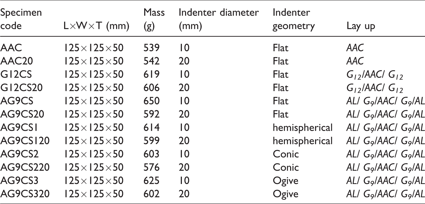

Macrostructure schematic of experiments configuration with the same dimensions.
Quasi-static tests
In order to demonstrate the efficiency of the proposed composite sandwich panels compared to plain AAC, flexural three-point bending and indentation tests were employed. As mentioned in the Physio-mechanical characterization of AAC section, for each sample configuration, three replicates were tested and the average value was reported, then compared together.
Flexural three-point bending
Flexural three-point bending tests were performed based on the EN-1351 standard code [29]. Photographs captured and videos during loading were recorded using the DIC technique. Deformations of top and bottom face-sheets and foam core were converted to stress–strain contours to validate the relative deformation fields in the tested AAC beam.
DIC measurement
The DIC technique is a full-field optical measurement which uses the mathematical correlation method to analyze different taken digital photos of a loaded specimen during a test [31]. It has some advantages including low requirements for the tests, simple implementation, and high accuracy compared to other optical measurements [32]. Therefore, the application of the DIC method is more suitable for testing structural components. In the current flexural three-point bending tests, the DIC measurement was employed to capture the crack extension and displacement distribution of the experiments at one side. As shown in Figure 4, a digital FASTCAM MH4-10K camera was employed to capture sequential images of the specimen crack growth at different loading stages. Prior to mounting the specimen in the test machine, white and black paint was sprayed to the surface of the test specimen to assist in a random high-contrast image. The white light lamp was used to illuminate the specimen to obtain a uniform light intensity over the specimen surface during loading tests and the DIC images were recorded automatically every 1 s. Using the mathematical correlation between the initial un-deformed and deformed images of the specimen surface at different loading stages, the full-field displacement of the damaged regions was obtained.

Test setup for DIC.
Indentation
Indentation test was conventionally performed for testing experiments to be confined by the surrounding material during compression loading [33]. Quasi-static indentation test has been used to understand the low-velocity impact response of a wide range of materials. A series of quasi-static indentation tests were conducted to examine the structural behavior of the proposed reinforced AAC blocks using two different diameters steel indenters. Damage initiation in composite sandwich panels strongly depends on the indenter geometry and boundary conditions [34]. To evaluate the effects of nose shapes as shown in Figure 5, flat, hemispherical, ogive and conic indenters were mounted in a standard 300 KN servo-hydraulic UTM and the load was applied at a nominal displacement rate of 2 mm/min considering three different boundary conditions. The force and displacement of the indenters were automatically recorded by a data logger connected to computer and MTS machine. Figure 6 shows the macrostructure schematic of manufactured fixtures to assess the effects of boundary condition on the mechanical response of experiments.

Indenters with different nose shapes and diameters (10 and 20 mm) used during indentation tests.

Macrostructure schematic of manufactured fixtures with different internal openings.
Results and discussion
Flexural three-point bending
Quasi-static flexural three-point bending tests were conducted on plain AAC blocks and composite sandwich panels and compared together to illustrate the effects of the face reinforcements on the structural behavior of beam elements.
As Figure 7 shows, the control AAC beam was loaded up to the ultimate failure load in an elastic regime. AAC undergoes a predominantly brittle failure with a single crack in the mid-span. From the load–displacement curve (see Figure 8) it is apparent that the maximum peak load of composite sandwich panels is superior, where the maximum peak load of FMLRAAC was 20% higher than the GFRAAC ones and they both show much more enhanced properties (70% and 40%) compared to plain AAC blocks respectively. The reasons for this behavior are being discussed in the following.

Fractured AAC block at the maximum flexural strength.

Typical load–deflection curves of flexural experiments.
In the presence of the skin layers, however, a pseudo-ductile behavior with multiple flexural and shear cracks in the core material and subsequently delamination of the skin elements at higher deflection levels is observed. Initiation of failure modes depends on the interaction of AAC core and face reinforcement characteristics.
When beam samples are subjected to flexural three-point bending, initially, it is followed by generation and growth of multiple shear cracks, especially in the region near the supports. Aluminum wrinkling also occurs when the local compressive stress reaches a critical value which depends upon faceplate and core modulus. This critical stress depends on the degradation of supporting core. This failure mode is a result of localized compression overcoming the effective bracing of the skin by the porous brittle core material. Also, delamination is another mechanism that causes subsequent drops in flexural curve especially in case of GFRAAC panels. Plastic deformation of the core material, due to a combination of compression and shear stresses, degrades the supporting role of the core and experience other failure modes, such as face sheet debonding. Distributed cracks and subsequent delamination are mechanisms in the face skins imparting in toughening the panels by improving the energy absorption capacity and residual strength and totally delaying of the ultimate failure of the core element. Damage generation of sandwich beams maybe due to the results from catastrophic core shear failure; meanwhile, the face plates are still intact and debonded as shown in Figure 9. The presence of woven glass fibers also improves the bending strength GFRAAC panels and promotes crack bridging mechanism resulting in higher residual strength and enhanced energy absorption (see Figure 8). Also apparent is the enhancement in flexural strength from 0.4 MPa for plain AAC specimen to 2.9 MPa for FMLRAAC. At the advent of delamination, widening of the major flexural cracks along the depth is restricted which promotes additional flexural cracks further enhancing energy absorption capacity. In some cases, the core and face sheet elements lose their mechanical integrity. Furthermore, even if FML does not absorb much energy in the composite, it contributes to delay the perforation so that more deformation energy is absorbed [35].

Failure modes of (a) FMLRAAC and (b) GFRAAC under flexural three-point bending.
Crack growth and deformations also were studied through DIC technique with a high-resolution digital camera. The unique pore structure of AAC core material was used as a random, isotropic, and required for DIC system. The displacement area is determined by tracking the movement of a pixel subset from the reference image to deformed images. A commercial software GOM run by Correlated Solutions Inc. was used to process image analysis. The failure mode of the specimen was characterized as shear cracks generated from supports and debonding. Figures 10 and 11 show the typical crack distribution in the FLMRAAC and GFRAAC through the thickness of the specimen, respectively. The calculation regions for the displacements along the x-direction are at the center of the specimen. In particular, the software calculated the equivalents fracture strains as is evident in counter bars attached to the sequential pictures captured during the tests. It is worth noting that DIC results well followed the load–displacement curve obtained from UTM. The result indicates that insulated panels, FMLRAAC, and GFRAAC undergo much more strains to reach the fracture point approximately 400% and 200% respectively, compared to plain AAC. The obtained amounts revealed the effectiveness of incorporation of FML system as reinforcing the material; also, the DIC technique predicts the overall and local structure movements correctly as a remote device control.

DIC-captured images during the flexural three-point bending test of GFRAAC beam.

DIC-captured images during the flexural three-point bending test of FMLRAAC beam.
Indentation
A series of quasi-static indentation tests were performed on the specimens. Load–displacement curves were recorded and by integrating the area under these curves the absorbed energy was calculated. Damage mechanisms in composite sandwich panels visually were identified by means of characterization of specimen’s failure modes in the top, bottom and through sectional views. For the case of FMLRAAC panels, effects of indenter diameter, nose shape, and two more boundary conditions were also investigated in the following sections.
AAC blocks
AAC blocks with dimensions of 125 × 125 × 50 mm were clamped between the steel frames with an internal opening diameter of 100 mm. Indentation tests were conducted using 10 and 20 mm diameter flat ended indenters. Tests on AAC blocks were conducted in order to identify the possible relationship between indentation and damage mechanism of core material in sandwich composite panels. Furthermore, in order to identify the failure modes through the thickness of samples, a schematic is presented. Figures 12 and 13 depict the faces and schematic through the sectional view of an indented AAC block with flat indenters respectively. Typically, the load–displacement trend exhibited initially a linear trace, associated with elastic deformation in the AAC, followed by a secondary, fluctuating steady state region involving the tunneling of the indenter through the thickness of the AAC and finally a sudden drop due to failure of the block. At the beginning of loading, under the tip of the indenter, AAC experiences elastic deformation, brittle failure and sudden collapse of cell walls. A crushing region initiated and propagated in front of the indenter through the material. In this region, the cells have collapsed and the density is much larger than its initial value where the cells have collapsed and the density is much larger than its initial value. The response during the indentation process is dependent on the fracture properties (cell wall buckling) of the AAC core as well as indenter geometry. Moreover, by moving through the thickness, major tensile cracks generated and propagate radially which forms a cone shear cone plug backward the sample. In the remaining material, the deformation can be assumed to be essentially elastic with low particle velocity and density identical to its initial value. A combination of failure modes comprising of compression, tension and shear govern the failure modes of insulated panels which is apparent in the top and rear face of AAC. Similar responses can be observed in Flores-Johnson and Li for Rohacell and Airex foams where the presence of both a cone shape shear zone and tensile radial cracks are in evidence [18]. The specific mode of failure is likely that combinations of such mechanisms lead to the final failure governed by diagonal tension and shear cracks in the AAC.

Indented AAC block from (a) front (b) rear view prior to complete indentation; the red line shows the direction of through sectional view of AAC.

Through sectional schematic of indented AAC blocks by 10 and 20 mm diameter indenters.
Sandwich-insulated AAC panels
Effects of top and rear face reinforcing of AAC blocks with woven E/glass fiber sheets and fiber metal (aluminum) laminate named as GFRAAC and FMLRAAC are obtained and reported. As shown in Figure 14, it is apparent that despite the linear response of plain AAC panels to indentation, SIPs show a nonlinear response which is characterized as below.

Load–displacement curves of experiments indented by 10 mm diameter flat ended indenter.
Localized indentation response of composite sandwich panels is generally categorized as (1) local perforation in the vicinity of the tip of the indenter and (2) large deformation of the surrounding face sheets in the form of wrinkling and delamination (top and rear skins) and, (3) permanent plastic deformation in the form of core cell wall crushing as well as densification. Rizov also investigated the quasi-static indentation response of closed cell PVC foam with different thicknesses of GFRP skin and shows that the panels generally exhibited a non-linear load–indentation response, due to local foam crushing under the indenter [36]. Load–displacement plots following indentation tests on composite sandwich panels based on the cross-linked AAC show two distinct peaks in the load–displacement trend, associated with failure of the upper and lower face sheets, are in evidence. After a series of shear cracks, a plateau regime was observed, during which time the load was maintained. In this regime, the load was lower than the initial failure load resulting in an apparent strength loss of the sandwich panel. This is mainly due to the transfer of shear resistance from the strong composite face sheet to the weak AAC core. Some fluctuations are evident in load–displacement diagrams especially during moving the indenter through core material which can be attributed to the sequential cell wall buckling, collapse, and densification of the material as well as progression of indentation which are reported in some previous studies [18,37].
As expected, the specimens with FML face sheets resulted in higher peak loads and thus resulted in higher energy absorption values. Between these peaks, there is a region where the force remains roughly constant, associated with the indenter penetrating through the AAC core (tunneling). The energy absorption, as well as the specific absorbed energy (SAE), is almost linearly proportional to the face sheet composite configuration [35].
For GFRAAC specimens, top face sheet of the composite panels undergoes the compression and pure shear stresses resulting in disk shape piercing and by moving the indenter rear face sheet subjected to fiber breakage in the form of petalling (see Figure 15). Delamination also is another damage mechanism of face sheet during penetration which is observed and inspected through C-scan (see Figure 21). A schematic side view of the composite sandwich panels is shown in Figure 17 wherein diagonal tension cracks and shear cracks can be seen emanating from the region near to the rear face sheet. An important observation during tests on specimens relates to the debonding between lower aluminum skin and the adjacent composite ply, which may happen during indentation. This is believed to be responsible for higher energy absorption and further perforation resistance of FMLs during high-velocity impact. The bond area between the glass fiber sheets and the aluminum layer is a point of weakness during indentation, whereas at low-velocity impacts, the composite–metal adhesion remains impressive under the loading. As a consequence, the tendency of debonding between aluminum and glass fiber plies is significant and the aluminum skin can dissipate more energy through membrane deformation. This free deformation results in superior perforation performance of FMLRAAC compared to its counterparts GFRAAC. Also, with this event, FML skins may contribute better in energy dissipation compared to GFRP systems (see Figure 16).

Indented GFRAAC specimen from (a) front (b) rear view.

Energy–displacement curves of experiments indented by the flat ended indenter.
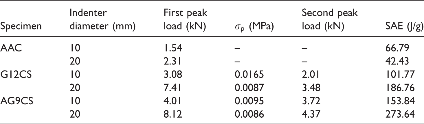
In the plateau regime, the further increase of the local contact force resulted in face wrinkling and face/core debonding, which caused a degradation of structural integrity, leading to a subsequent failure stage characterized by the continuous decrease of the load. Variations of failure load and displacement at failure are attributed to the small difference in the dry density of the specimens and difference of face/core debonding in the specimens. Comparing the SAE item given in Table 5, it is seen that FMLRAAC and GFRAACC composite panels show 52% and 130% improvement in mechanical properties compared to plain AAC for 10 mm indentor also, 340% and 544% for 20 mm one, respectively.
Experimental peak load and energy values.
Effects of indenter diameter
Figure 18 shows the cross-sections of plain AAC and reinforced composite panels following indentation by a 10 and 20 mm diameter flat ended indenter. The pictures were taken through the perforated region in each specimen to illustrate the effects of diameter on induced damages. The indenter has moved through the AAC results in cone-shaped plugged, with the diameter being proportional to that of the indenter suggesting that the AAC fails predominantly in a shear mode.

Schematic model of damage sequence. a) Upper face sheet wrinkling, b) penetration and crushing and c) Global bending and perforation.

Through sectional view of indented AAC, GFRAAC and FMLRAAC with (a) 10 and (b) 20 mm diameter indenter.
A change in failure mode was observed in damage evolution in bigger indenters, where a cone shear plug generated after a certain penetration. Tunneling was apparent in the lower half of the specimen perforated with 20 mm diameter indenter. In contrast, reinforced AAC blocks fail in the mixed-mode of failure regarding global bending and delamination, totally tearing the aluminum skins in case of FMLRAAC. Thermography and C-scans reveal damages that include matrix cracking, fiber breakage and delaminations in face sheets as mentioned [34]. In this regard, the front face scanned image of total delamination area of GFRAAC panels were captured and shown Figure 15. Here the delaminated zones are proportional to the indenter diameter (see Figure 21). Wu and Shyu [38] showed that the influence of the indenter diameter is significant when the contact load becomes very large. They showed that the delamination area increased with increasing impactor radius. As indentation force increases, the indenter is supported by an increasing crushed zone of densified material and the further crushing results in the local jumping-like response. Some noise emissions were also heard every time the force dropped in each oscillation. The increases of force in the plateau-like regime and the starting point of the plateau-like regime with the radius of the indenter in Figure 19 depend on the radius of the head diameter of the indenter.

Load–displacement curves of FMLRAAC panels indented by flat nose shape indenter.
Circumferential cracks start to propagate under the tip of larger radius indenter and in some cases cause overall separation of AAC core. Smaller diameter indenter in a more likely way causes fewer radial cracks and smaller cone shear plug. It is worth noting that in composite sandwich panels under the indenter nose a disc shape plug was formed as a consequence of compressive stress transformations in fracture zone around the periphery of the indenter. Wen et al [39] also reported the formation of a disk shape zone in the woven glass/polyester panels under the low-velocity impact of flat and blunt cylinders.
Energy absorption (toughness) is measured as the area enclosed in the load–deflection response. Therefore, the absorbed energy can be normalized by the plate thickness in order to compare the efficiency of proposed composite sandwich panels. The energy absorption capacity of FMLRAAC panels is profound almost 300% and 200% more than the plain AAC core material. The trend of energy values is incrementally ascending by increasing the indenter diameter except for plain AAC panels (see Figures 19 and 20). For larger indenter diameter, the onset of radial shear cracks occurs quicker than the smaller one because the core material is brittle and after the first major crack fails and breaks into some pieces, fewer amounts of energy are absorbed. But in case of SIPs, the overall composite sandwich panels do not fail immediately after core fracture and withstand the indenter pressure until the rear face sheet lost its structural integrity thereby more energy dissipated. As a matter of fact, a catastrophic failure of the brittle AAC could be prevented by reinforcing both faces.

Comparative diagram of energy absorption by the AAC, GFRAAC and FMLRAAC specimens with two different diameters of indenter (flat nose shape).

Front view scanned image of the delamination area of GFRAAC indented by (a) 10 mm indenter (b) 20 mm indenter.
Effects of indenter nose shape
Indentation and penetration behaviors of SIPs loaded by rigid indenters depend mainly on the stacking sequence and material properties of the target, load rate and geometry of the indenter (i.e. nose shape, diameter, and length of indenter) [40]. Typical load–displacement curves of flat, hemispherical, conic and ogive ended indenters for FMLRAAC are derived and depicted in Figure 22. Load–displacement curves initially show an elastic regime at very low strains especially in case of the flat indenter, until reaching a peak load which is the onset of plastic failure of top FML face sheet. After the first peak, a sudden drop due to FML perforation occurred; therefore, the curve experiences roughly in a plateau regime characterized by a steady increase of the force as a consequence of the additional force required to tear the cell walls at the perimeter of the indenter. The load–displacement slope gradually increases with further indentation while contact area of indenter and panels increases. The damage progression of the FMLRAAC from the longitudinal and transverse cross-section was captured using an optical microscope. Figure 24 illustrates the generated shear cracks in FMLRAAC layers which were induced by the indentation force. As shown in the figure, the shear cracks propagate in the second face sheet due to the bending as well as shear stress rather than in the first interface because the first sheet is restrained by the compressive stress field around the contacted position of the indenter. Also, it is evident that the onset of delamination occurs between the FMLRAAC layers due to the growth of the shear cracks in the FMLRAAC layers. As the indenter pierces through the aluminum skin, it bends back material around the periphery of the indenter. This phenomenon is the so-called petalling.

Load–displacement curves of FMLRAAC indented with different nose shape indenters.
As expected, the indentation force at a given indentation depth increases with the decrease of indenter nose shape angle, due to the increase of the axial contributions from the crushing stress. For the blunt noses indenters, i.e. (flat and hemispherical), a crush zone in front of the indenter nose tip was observed. However, for the sharper ones (conic and ogive), no crushing zone was seen in front of the tip of the nose. It should be noted that, the mode of failure for the perforation of aluminum sheet by hemispherical is associated with high plastic deformation and tensile crack on the back side, whereas a disc-shaped plug out caused by shear failure visibly after perforation with less plastic deformation by ogival indenter resulted in lower perforation energy (see Figure 23).
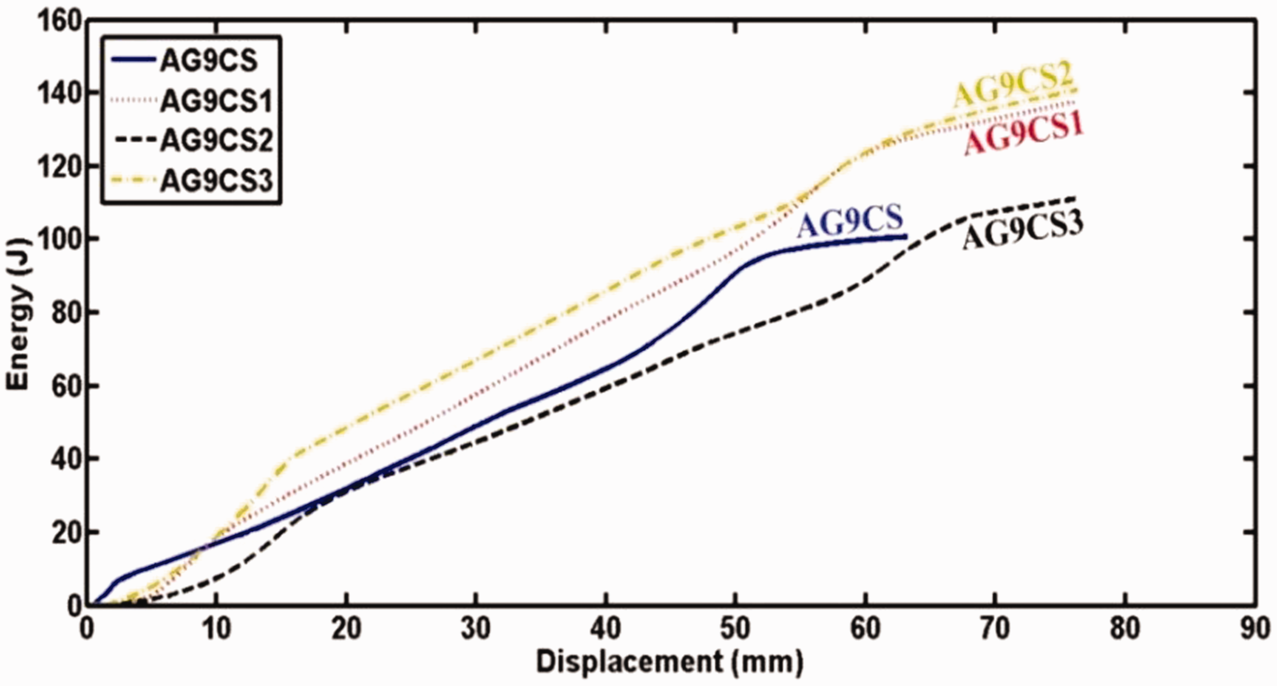
Energy–displacement curves of FMLRAAC indented with different nose shape indenters.

Through sectional and rear view of FMLRAAC panels indented by (a) Flat (b) Ogive (c) Conic and (d) Hemispherical indenters respectively.
Effects of boundary conditions
Three types of boundary conditions were studied to evaluate the energy absorption of each part of the panel. The amounts of first and second peak loads in the load–displacement diagram of FMLRAAC panels in Figure 25 are apparently related to load bearing property of composite face sheets. The first peak is approximately equivalent for each type of boundary conditions as well as the plateau region. It is interesting to note that a higher second peak load is observed for fully fixed boundary condition with the least span which is due to the high degree of constraint and transverse of shear loads associated with failure of the lower composite skin.

Load–displacement curves of FMLRAAC with different boundary conditions.
Considering the total SAE per unit volume, FML face sheet with a higher degree of constraint, i.e. fully fixed boundary condition and glass fiber face-sheets all resulted in higher absorbed energy. Moreover, three deformation modes were observed in the sandwich panels: localized upper face sheet indentation, global bending with cores crushing and localized lower face sheet indentation. Crushing of foam core occurred before the failure of the bottom face-sheets and in the meantime, debonding was observed especially in the case of panels indented with bigger radius.
Core face debonding also absorbs some energy during penetration of an indenter, and seems to be dependent on the bond strength between the face skins and, AAC core material. Localized fiber breakage, fiber delamination and core crushing, are the primary failure mechanisms in the reinforced AAC panels. The total absorbed energy of FMLRAAC panels is the area under the load–displacement curve, which is shown in Figure 26. Moreover, adhesive and surface condition of face-sheets also affects the total absorbed energy. The first and second peak loads of SAE were evaluated, and listed in Table 6. This indicates that the span length of fixture contributes to specific energy for specimens. SAE parameter was calculated which indicates that fixture b and c absorb 5% and 22% energy, respectively.
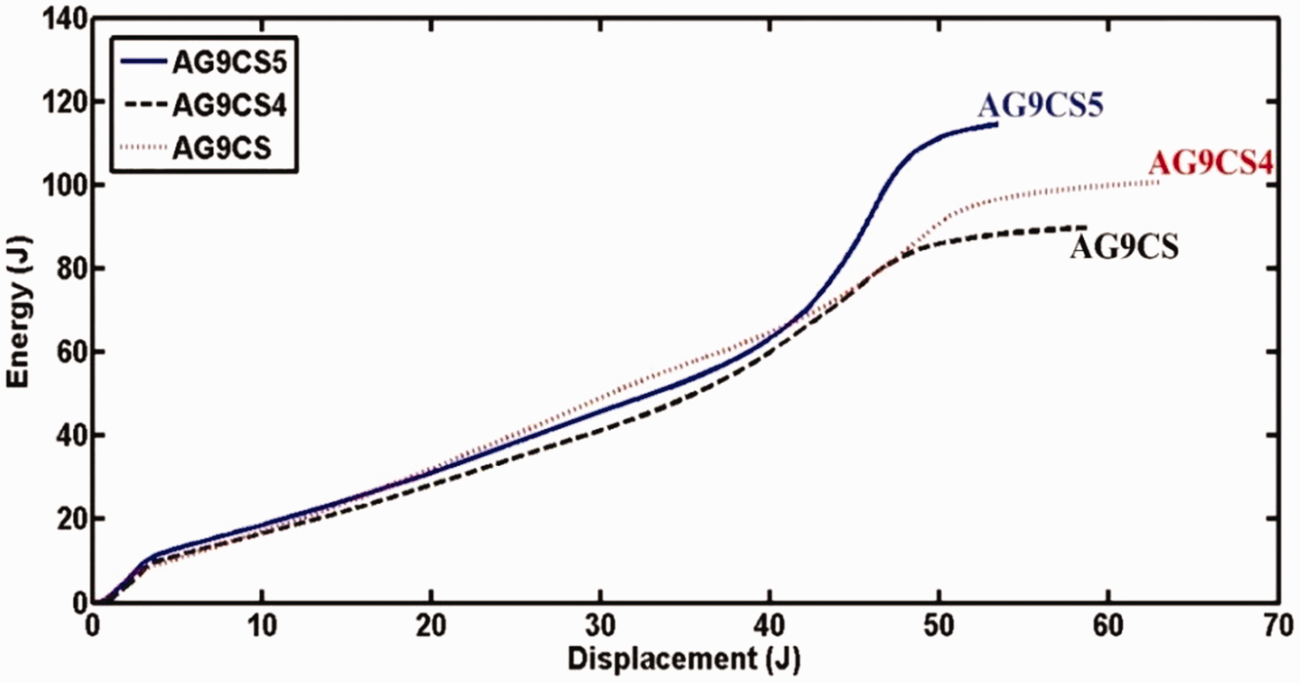
Energy–displacement curves of FMLRAAC with different boundary conditions.
Obtained load and energy values.

Stacking FML as a reinforcement system improves the mechanical strengths of the AAC core material; furthermore, considering these impressive features is truly an effective reinforcing concept imparting in both local and global response of composite sandwich panels effectively. The catastrophic fracture of fiber sheets can be restricted in FMLRAAC panels because despite the absorption a relatively small portion of flexural energy it delays the overall failure and stability of panels. It is attributed to high deformation capacity of aluminum face plate which absorbs more energy. The similar result is also reported in an experimental study by Caprino et al. [41] indicating the progression between failure modes initiation in FMLs. The study is also based on the same deflection profile for several specimens that have similar stiffness.
Conclusions
The mechanical behavior of composite sandwich insulated panels with AAC core material was investigated experimentally under quasi-static flexural three-point bending and indentation tests. For this reason, a combination of woven glass fibers plus aluminum sheets were utilized as face skins reinforcement. Load–displacement and SAE of experiments were measured and compared together. In addition, the load–displacement curve and crack propagation of specimens under flexural three-point bending were tracked successfully through the DIC technique.
It was found that face reinforcement of AAC beam elements noticeably improves the load bearing capacity, energy absorption, and flexural strength. The contributions of skin layers to improve the indentation resistance were documented; meanwhile, it is figured out that indenter nose shape has a slight effect whereas increasing indenter diameter resulted in more deterioration and delamination of faceplates as well as core/face debonding. Material ingredients, interfacial bonding as well as boundary conditions highly affect the overall mechanical behavior of the composite sandwich insulated panels. Moreover, because FML is noncorrosive, there would be no corrosion problems for the FMLRAAC panels, as is the case with aluminum-reinforced AAC, and the AAC would be protected from harsh environments due to the protective face skins; at the same time, it carries the high shear stress. These insulated panels could be produced in spans of several feet and they could be easily insulated in required positions. Insulating AAC blocks with such composite sandwich sheets could, therefore, be a reliable option in reinforcing existing building components to improve their mechanical behavior. The application of such SIPs in construction can also improve housing safety and extension of their design life.
Footnotes
Acknowledgments
The authors thank Mr. Ahmadi, the managing director of Parin Beton, for the technical support.
Declaration of Conflicting Interests
The author(s) declared no potential conflicts of interest with respect to the research, authorship, and/or publication of this article.
Funding
The author(s) disclosed receipt of the following financial support for the research, authorship, and/or publication of this article: The authors thank the Tarbiat Modares University for the financial support.