
Abstract
Sandwich systems are gaining prominence because they offer thermal insulation in many building structures. There is a growing interest in better understanding the behavior of sandwich structures, as well as there is a need to monitor and predict the consequences of the limitations and weaknesses inherent in their design. The aim of this study is to evaluate the effect of two types of core materials on the bending properties of textile reinforced concrete (TRC) sandwich beams. In TRC, bi-directional glass textiles were used as reinforcement along with fine grained cementitious binder. TRC sandwich beam consisted of gypsum or calcium silicate panels with different density as core and TRC as skins. The stress transfer between skin and core was attained using adhesive tension without the use of mechanical anchors or adhesives. The bending properties of TRC sandwich beams including the effect of number of layers of textile in the TRC skins and independent behavior of core materials were investigated using three-point bending test. The properties such as flexural strength, toughness and residual strength have been evaluated for all specimens. Feasibility of using ASTM guidelines has been explored in estimating the toughness of various TRC systems. The general outcomes of this investigation promise a good influence for the application of gypsum and calcium silicate as core material for sandwich structures.
Introduction
Textile reinforced concrete (TRC) is a novel high performance cement based composite reinforced with glass, carbon, basalt and aramid textiles for various applications. TRC systems help to enhance tensile strength and rigidity as well as add ductility to infrastructure systems. TRC have been used extensively in wide range of structural and non-structural applications and for strengthening of existing concrete and masonry structure [1–3]. TRC sandwich panels were initially proposed by Hegger et al. [4] and promising results were seen about the mechanical behaviour under various loading conditions. TRC is considered as a suitable material for sandwich construction due to its merits such as light weight, higher tensile strength, durability and ease of application in any surface profile [5]. One of the main advantages of integrating TRC in sandwich panel application is towards increasing thermal efficiency, since it can acts as a thermal insulator. To reduce the heat transfer in sandwich panels, materials like polystyrene or polyurethane are used as core materials; for such systems it is seen that the efficiency depends on the material density and thickness of the panels.
Independent characterization of TRC’s bending response has been studied regarding the textile characteristics [6]. The type of fiber material used in textile and the density of textile in warp and weft directions found to influence the flexural toughness. TRC is a fairly new building material, investigating the action of sandwich beam with TRC as skin and its interaction with various core materials is an upcoming research field that has the potential to be used in different applications. Some of the core materials studied to date are TRC combined with core materials such as expanded polystyrene (EPS), aerated aerocon concrete, and foamed concrete. Colombo et al. [7] studied a multi-layer prefabricated façade sandwich distinguished by an internal insulation layer constructed from expanded polystyrene foam and two outer layers of Fiber Reinforced Concrete for use in an existing building’s exterior façade panel for energy retrofitting. Mo et al. [8] developed a high-temperature resistant lightweight aggregate mortar reinforced with basalt textiles as skin layer for use in TRC sandwich concrete composite along with aerated concrete as core. Compared with traditional EPS foam as the core material, the TRC sandwich beam had a stronger flexural strength/weight ratio and no substantial harm was observed on the sandwich concrete composite when exposed to direct flame. In the context of sandwich construction, Gypsum and calcium silicate is used as insulation in various constructions; however integration of these materials with TRC is novel and not reported till date. Hence in the present study, the gypsum and calcium silicate is used as core material along with TRC skin and investigations are carried out to understand the bending response.
Investigations were also reported in literature related to the shear transfer in TRC sandwich systems. Generally shear transfer in sandwich beams can be either with the help of shear connectors or by means of adhesion between various materials. In one of the study, the shear transfer was enabled in a panel by applying polymeric material and by means of mechanical anchors [9]. A sandwich system consisting of two facings made of carbon reinforced Textile Reinforced Concrete, a low density foamed concrete core and glass fibre reinforced polymer connecting devices was investigated by Portal et al. [10] In the present investigation the bond between the core material and TRC skin is achieved by the adhesion of binder used in TRC and without using any mechanical anchors or external adhesives. Similar approach was also proposed by Prisco et al. [11] for TRC sandwich panels while using TRC skin. Even though flexural capacity and method of failure has been studied in literature for sandwich beams, there is lack of information about toughness of such systems, which is a relevant parameter towards assessing the ductility of various structures. Independently, the plain core material in sandwich beam is weak in tension and it absorbs very minimal amount of energy during fracture. However, when it is combined with skin materials that are added at both compression and tension face, the sandwich beam absorb more energy (i.e, toughness and ductility enhances). The toughness is the vital parameter of any structure while subjected to various loading conditions such as monotonic, cyclic or repeated loadings. There is a lack of characterization methods for determining toughness of sandwich systems. In this context it should also be noted that, there is limited guidelines available to determine the toughness value of concrete composites, and ASTM C1609 [12] is used for finding the residual strength and toughness of discrete fibre reinforced concrete under three point bending.
In the present investigation continuous bi-directional glass textile is used as reinforcement, which helps to enhance the toughness of TRC skin and also that of the sandwich beam. Two core materials gypsum and calcium silicate has been introduced in TRC towards sandwich construction and the bending performance has been investigated to study the feasibility and optimal performance of such systems. ASTM guidelines have been followed to determine toughness at specific deflections in various TRC systems.
Experimental investigation
Flexural tests were carried out on TRC sandwich beams with two different type of core materials gypsum and calcium silicate panel. Flexural beam specimen is considered as the basis for quantifying the toughness due to textile incorporation and also for core material integrated TRC sandwich beams. The material performance is characterized in term of areas under the load-deflection curve. In addition, the residual strengths are determined directly from the load vs. deflection curve. Number of textile layers in TRC skin was varied to find their influence on the overall behaviour. The details about the investigations are presented in the following sections.
Materials used
TRC consists of a fine grained cementitious binder and alkali resistant glass textile as reinforcement. The diameter of glass filament is 14 µm, as given by the manufacturer (actual diameter of the coated filament was 20 µm) and the mesh size in both the directions is 25 × 25 mm and the weight per unit area is 225 g/m2. Cementitious binder system using normal sand of gradation varies from 0 to 2.5 mm was used and the density of the binder is 2050 kg/m3. Gypsum and calcium silicate core panels are commercially used wall panels having many superior properties and performance. Gypsum panel is composed of dihydrate of calcium sulphate of density 668 kg/m3 and unit weight of 4 kg/m2 and calcium silicate panel is derived from limestone and diatomaceous earth of density of 1250 kg/m3 and a weight of 8 kg/m2. The chosen core panels have the advantages of excellent heat and thermal resistance, sound insulation and durability.
Specimen preparation
To study the performance of core material under flexure, six panels were tested; the dimensions of the specimens are given in Table 1. A total of 18 sandwich beams were cast and tested and categorized in six groups. First, second and third group using gypsum core with 3, 4 and 5 layers of glass textile and the fourth, fifth and sixth group 3, 4 and 5 layers of glass textiles with calcium silicate as a core material. The TRC skins were produced by means of a wet hand-layup technique. The TRC sandwich panels were produced with a water binder ratio of 0.18. Textile was cut and trimmed for the required size and placed in the mould. Textiles with 3, 4 and 5 layers were placed by pressing such that binder perforations are ensured within the yarns and covered with binder and the textiles are positioned at 6 mm from the bottom edge of the panel. After 24 hrs the specimens were removed from their formwork and stored in a dry and sealed environment of 30°C until testing. The dimensions of the specimens are given in Table 2. Figure 1(a) and (b) shows the beam mould and the cast TRC sandwich beams. Nearly, 20% and 40% reduction in weight for TRC sandwich panel with calcium silicate and gypsum board as a core material is achieved compared to TRC alone specimen.
Core specimen details.
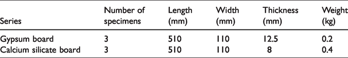
TRC sandwich beam details.
(a) Typical casting using mould and (b) demoulded specimen.
Test details
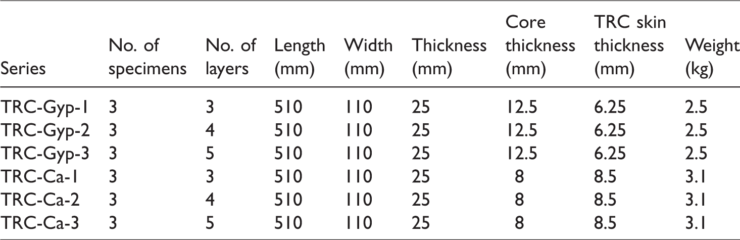
Flexural behavior of gypsum and calcium silicate panel, TRC specimens and the TRC sandwich beams were evaluated as per ASTM 1609 [12]. The view of the test setup with gypsum panel, calcium silicate panel and TRC sandwich beam is shown in Figure 2(a) to (c) respectively. The test was carried out in displacement control test machine of constant displacement rate of 0.1 mm/min till failure. The mid-point deflection was measured using linear variable differential transducer. The applied load the deflections were recorded in a data acquisition system for further analysis.
Test setup (a) Gypsum board, (b) calcium silicate board, (c) TRC sandwich beam.
Results and discussion
Bending response
Figure 3 shows the load versus deflection plot of the gypsum and calcium silicate panel. The observation from the plot shows that calcium silicate panel withstood more load compared to the gypsum panel. This is due to the higher density of calcium silicate than the gypsum panel [13]. The increase in core density leads to increase in flexural capacity in calcium silicate panel. Figure 4 shows the flexural strength versus density plot for calcium silicate and gypsum panels. The ultimate flexural load capacity between the gypsum and calcium silicate panel is nearly 16%. Gypsum panel yields higher deflection than the silicate panel, due to presence fibre particles and bonded paper over the surface. Both the gypsum and calcium silicate panels the initial linear regime is almost same due the presence of naturally occurring cementitious system.
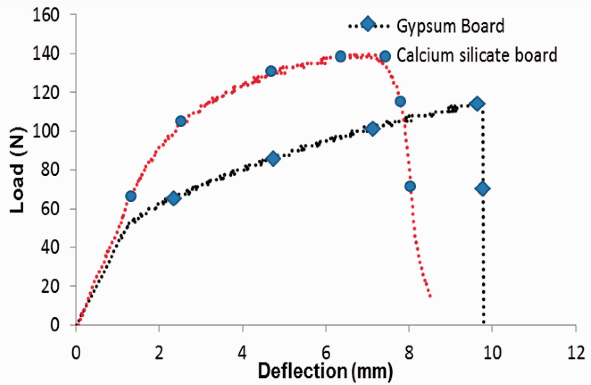
Load vs. deflection plot of gypsum and calcium silicate panel board.
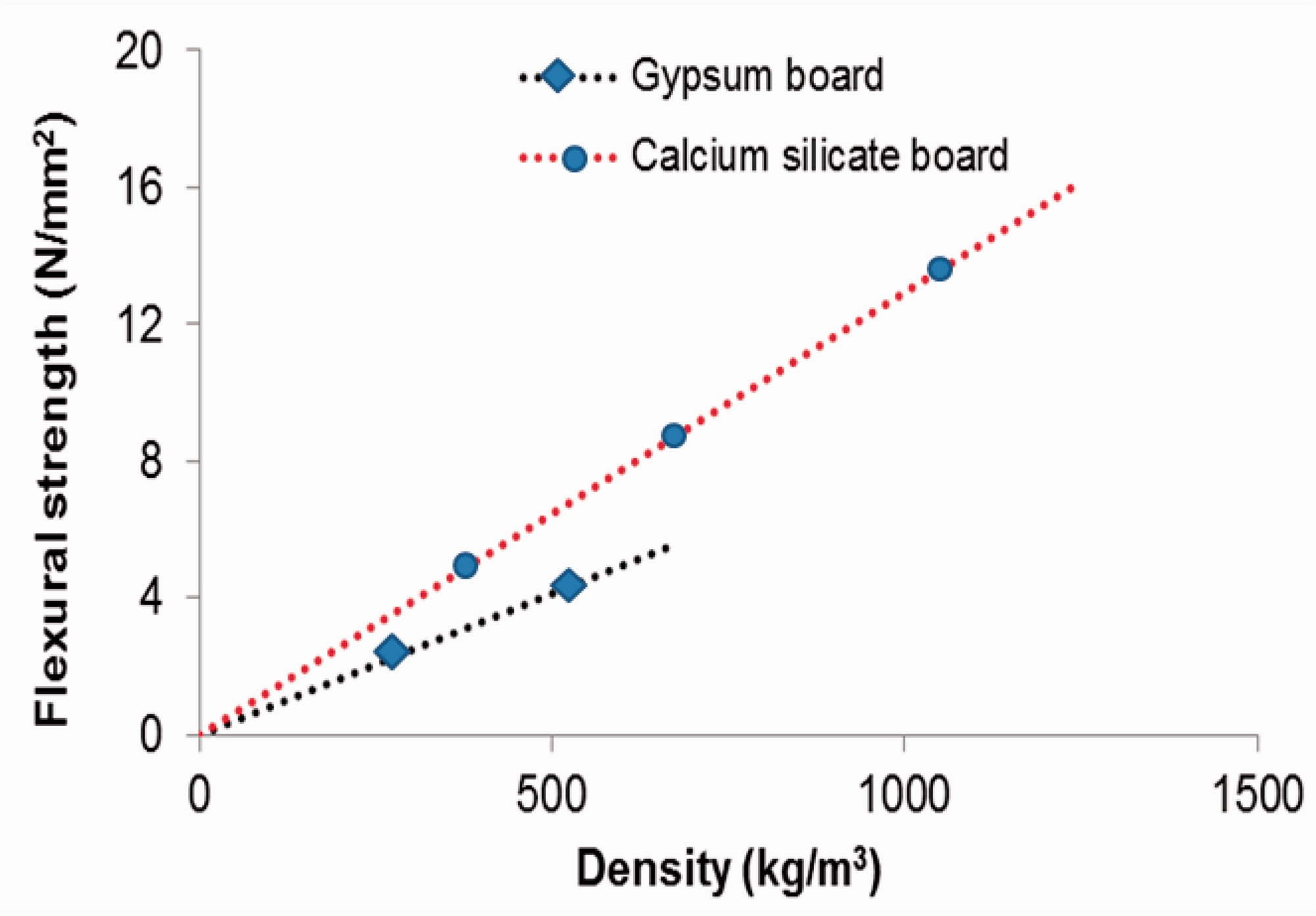
Flexural strength versus density.
Figure 5 shows the flexural load versus displacement response of 3, 4 and 5 layers of TRC skin without core material. TRC panels were tested and evaluated for flexural toughness as per at the limit of proportionality (LOP) and modulus of rupture (MOR). For TRC skin the LOP is measured from the load at which the first crack is observed. Similarly, for the MOR is measured from the highest load values of the TRC skin. The load versus deflection curve of TRC skin is linear elastic throughout the bending action and exhibited pre and post peak behavior in all the layers. In the TRC skin the presence of fibers leads to increase in deflection till reaches the MOR value and sudden decrease in the load resulting rupture of panels. TRC panels with 4 layers of fibres exhibited higher LOP and MOR compared to the 3 layer and 5 layer TRC panels. This may be due to the amount of cementitious mortar present in the fiber matrix, in 3 layers the amount of mortar is more and in 5 layers the amount of mortar is less for the chosen thickness. In the case of 4 layers panels the optimum amount of mortar is bonded between the fibers lead to increase in MOR and LOP. The values of LOP and MOR of chosen layer are given in Table 3.
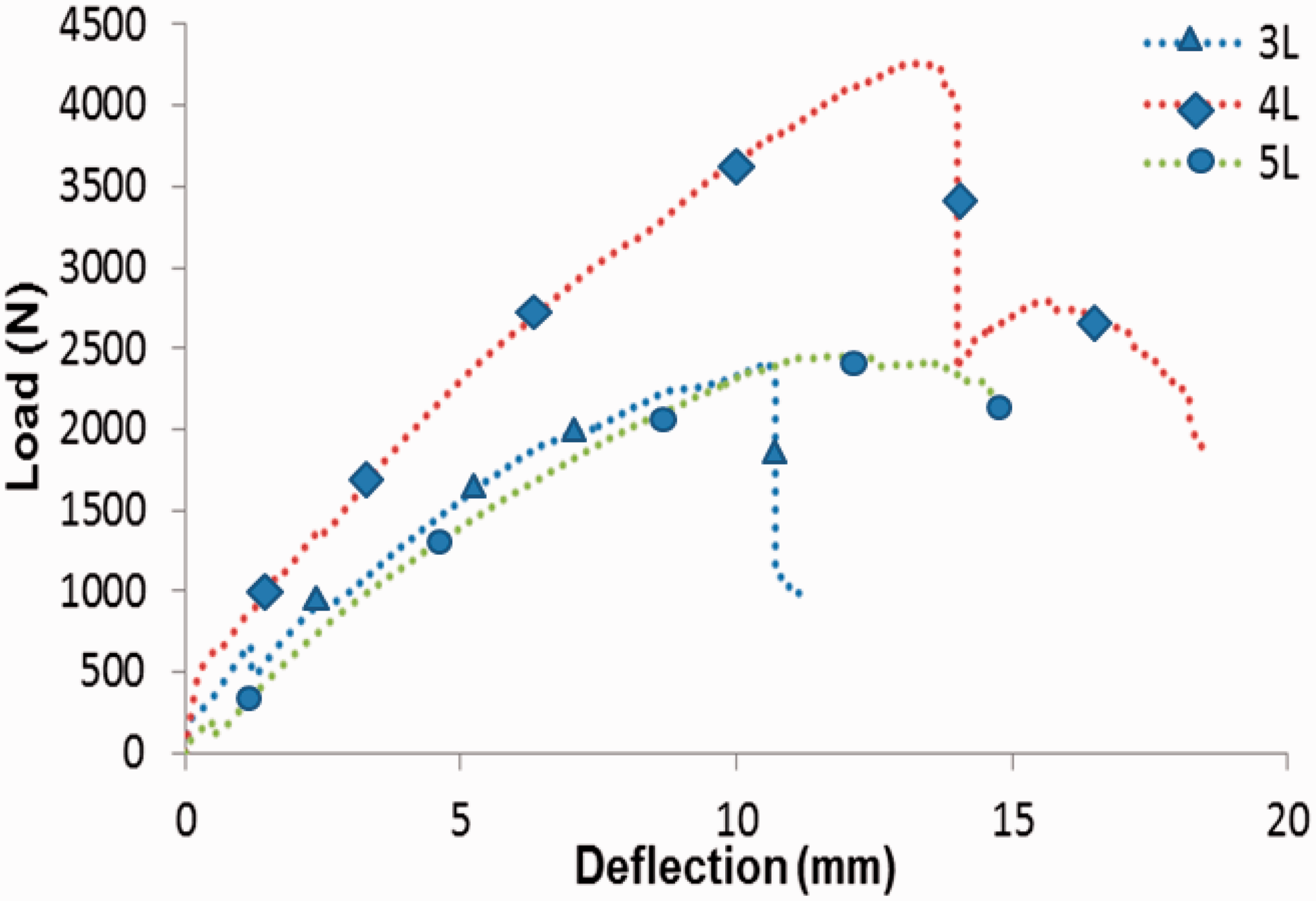
Load versus deflection curve for 3, 4 and 5 layers of TRC.
Limit of proportionality and modulus of rupture.
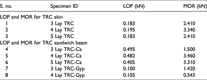
Figure 6(a) and (b) shows the critical values of the ultimate load versus number of layers and the first cracking load versus number of layers under flexural loading of TRC skin. From Figure 6 it is noticed that 4 layers of textiles can withstand more loads than the 5 layers of textile and the 5 layers of textiles shows ultimate and first cracking load compared to the 3 layers of TRC specimen.
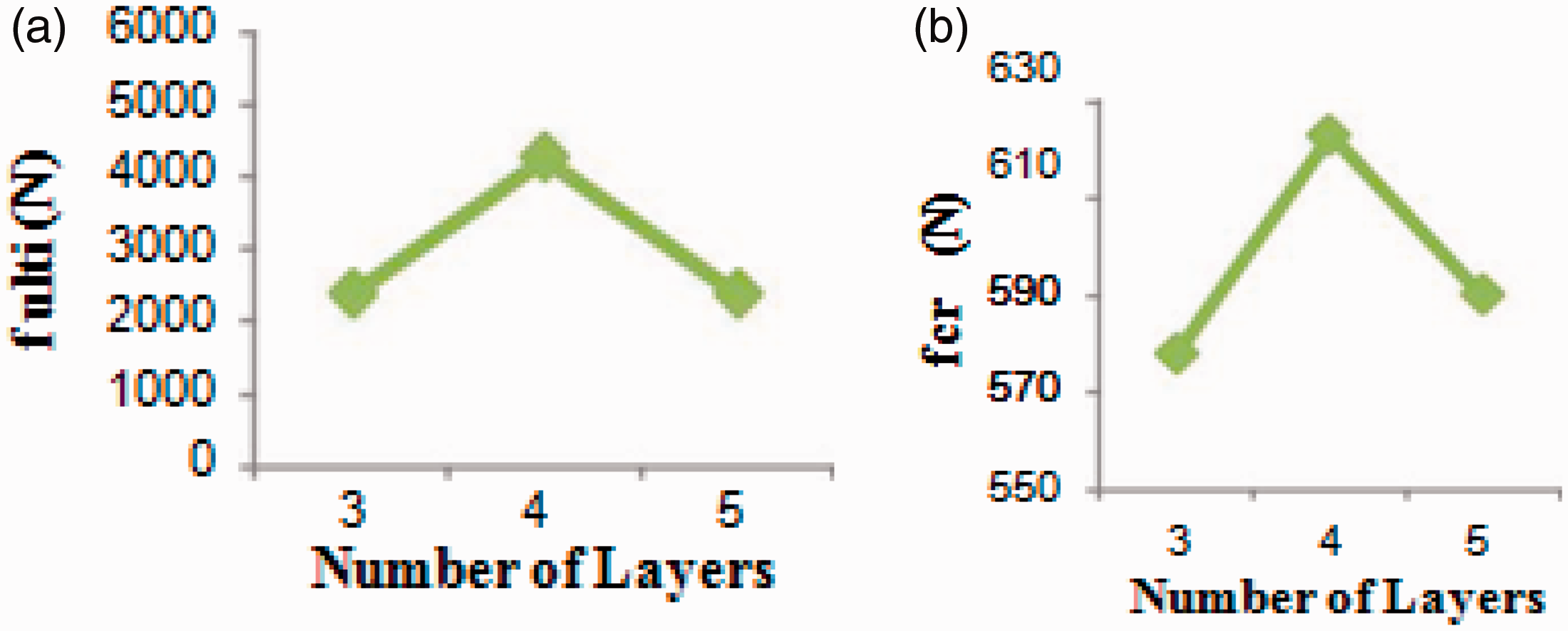
(a) Ultimate load vs. No. of layers for flexure test; (b) first cracking load vs. number of layers for flexure test.
Figure 7 shows the load versus deflection behaviour of TRC sandwich beam with gypsum as a core material with 3 and 4 layers of textiles in TRC skin. It is noticed that TRC skin with 4 layers of textile has lesser load carrying capacity than that of TRC with 3 layers. Further, with 5 layers of textile reinforcement, both textile delamination from binder and TRC debonding from gypsum core was noticed and results were negative. This may be due to the increased amount of textile fibre in the TRC skin, which initiated delamination between textile and binder before the core debonding and subsequently the lower density gypsum core fails suddenly. Whereas, in the case of TRC sandwich beam with 3 layers of textile in TRC skin, the bond between the textile and the binder was sufficient enough to delay the delamination in TRC, which has resulted in higher load carrying capacity. Further, it was also noticed that if the core thickness is increased, the delamination of the textiles occurs for thin skin of TRC. The ultimate load difference between both sandwich beam is nearly 40%. Figure 8 shows the load versus deflection curve of the TRC sandwich beam with calcium silicate as a core material with 3, 4 and 5 layers of textiles. From the Figure 8; 4 layers of TRC withstood more load compared to 3 and 5 layers TRC skin. Figure 8 shows 5.4% increase in ultimate load for 3 layers of TRC sandwich beam with 3 layers of textile in TRC with calcium silicate core compared to that of TRC sandwich beam with gypsum core. Also, 75% increase in ultimate load is observed for TRC sandwich beam with 4 layers of textile and calcium silicate core compared to that of gypsum core. This is due to the increase in core thickness and decrease in core density leading to delamination of the TRC skin first and subsequently the debonding of TRC skin from core. When core thickness increases, the possibility of failure initiation is expected in the skin material [13–15]. Due to such reason, it is seen that the ultimate load for TRC sandwich beam with 4 layers of textile and with gypsum core is reduced. Nearly, 5.5% load is decreased for 5 layers of textile compared to 4 layers with calcium silicate core. Figure 8 shows 30% of displacement is reduced for 3 layers of textile with gypsum core compared to calcium silicate core and 2% of displacement is reduced for 4 layers of textiles with gypsum core compared to calcium silicate core. The displacement for 3 and 4 layers of textiles with calcium silicate as a core is nearly same. Compared to the core materials (gypsum and calcium silicate) behaviour with the sandwich beam of gypsum and calcium silicate as a core nearly 92% and 91% of ultimate load capacity is increased respectively. Also, increasing the number of layers increased the bending load at the composite failure point while the effect of type of core material was not significant.
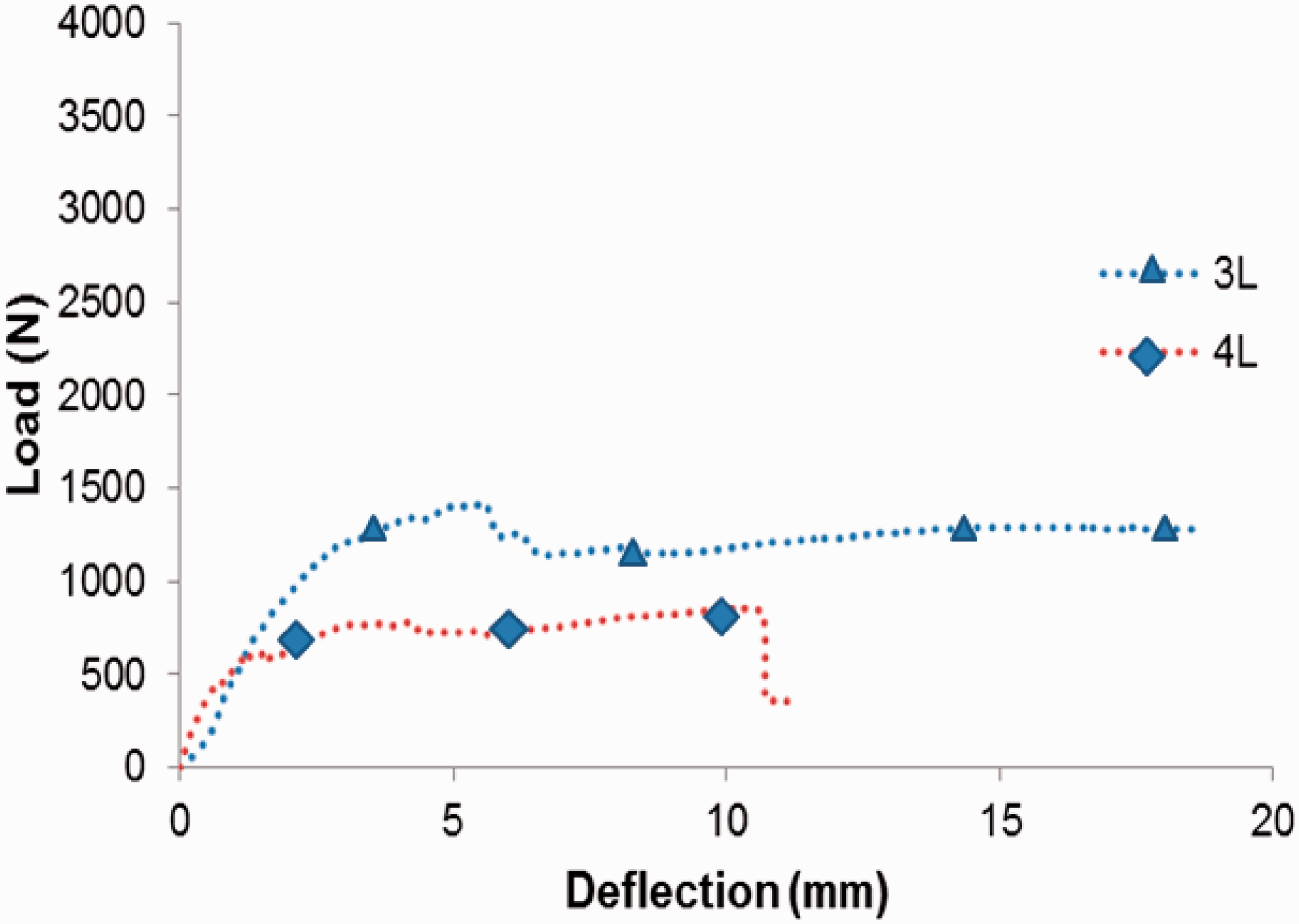
Load versus deflection curve for TRC sandwich beam with gypsum core.
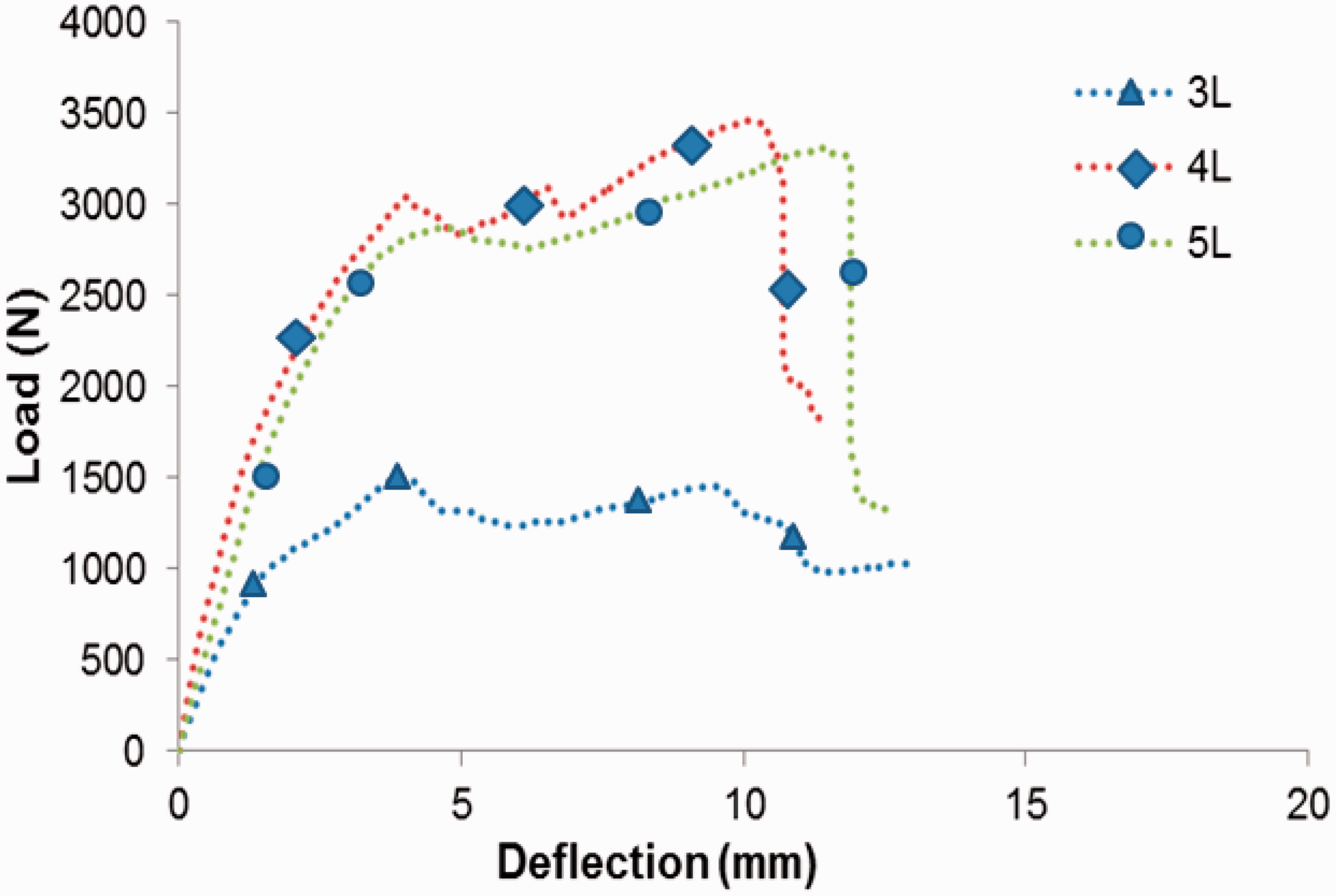
Load versus deflection curve for TRC sandwich beam with calcium silicate core.
Sandwich beam with TRC skin on both the compression and tension side were also tested under three-point bending. TRC sandwich beam with calcium silicate core exhibited LOP value of 0.495, 0.482 and 0.405 N-m for 3, 4 and 5 layer of TRC specimens respectively. In the case of TRC sandwich beam with gypsum core, the LOP is 0.10 N-m for both the 3 and 4 layer of TRC respectively. The LOP of TRC sandwich beam with gypsum core is less than the TRC skin without core. The lower stiffness of gypsum core tends to reduce the performance of TRC skin in both the compression and tension region. In the initial stages of loading the TRC skin in tension side is taking the load till the TRC skin cracks. After the skin cracks the failure is sudden and then the debonding occurs in TRC skin in the tension side. The bond between the gypsum core and TRC skin is not effective due to the shear failure. The increased core density in calcium silicate beam resulted in an increased shear transfer within the core, as well as more effective bond of the TRC skin. The values of LOP and MOR are given in Table 3. LOP for TRC sandwich beam with calcium silicate core is almost same for all the three layers and it is due to the increase in density. MOR value is higher for 4 and 5 layer TRC bonded calcium core, the density of the core tends to alter the behaviour of TRC skin in tension zone. The reason for the flexural load capacity and initial stiffness increase is observed by increasing the density of the silicate core for both 4 and 5 layers skinned beam. In the case of gypsum beam the load and initial stiffness tends to decrease due to lower density of the core material. The brittle nature of gypsum as a core material alters the TRC skin in tension and compression face even with the higher volume of fiber composites.
Failure pattern
For both the calcium silicate and gypsum panels, the mode of failure is inside bending of panels near the loading point. The failure mode is localized compression occurs in the loading point and in the linear regime. After the initial compression, the curve tends to deviate from linear to non-linear zone with the increase in the flexural load capacity for calcium silicate board and decrease in flexural capacity for gypsum boards. The failure of mode of gypsum boards is brittle in nature with a single crack in the loading point. The failure of calcium silicate board is controlled failure with single crack near the loading point. The gypsum panel the shape of the curve tends to show the strain hardening behavior and the calcium silicate panels shows the softening with smooth post peak behavior. Figure 9 shows the failure pattern of gypsum board and calcium silicate.
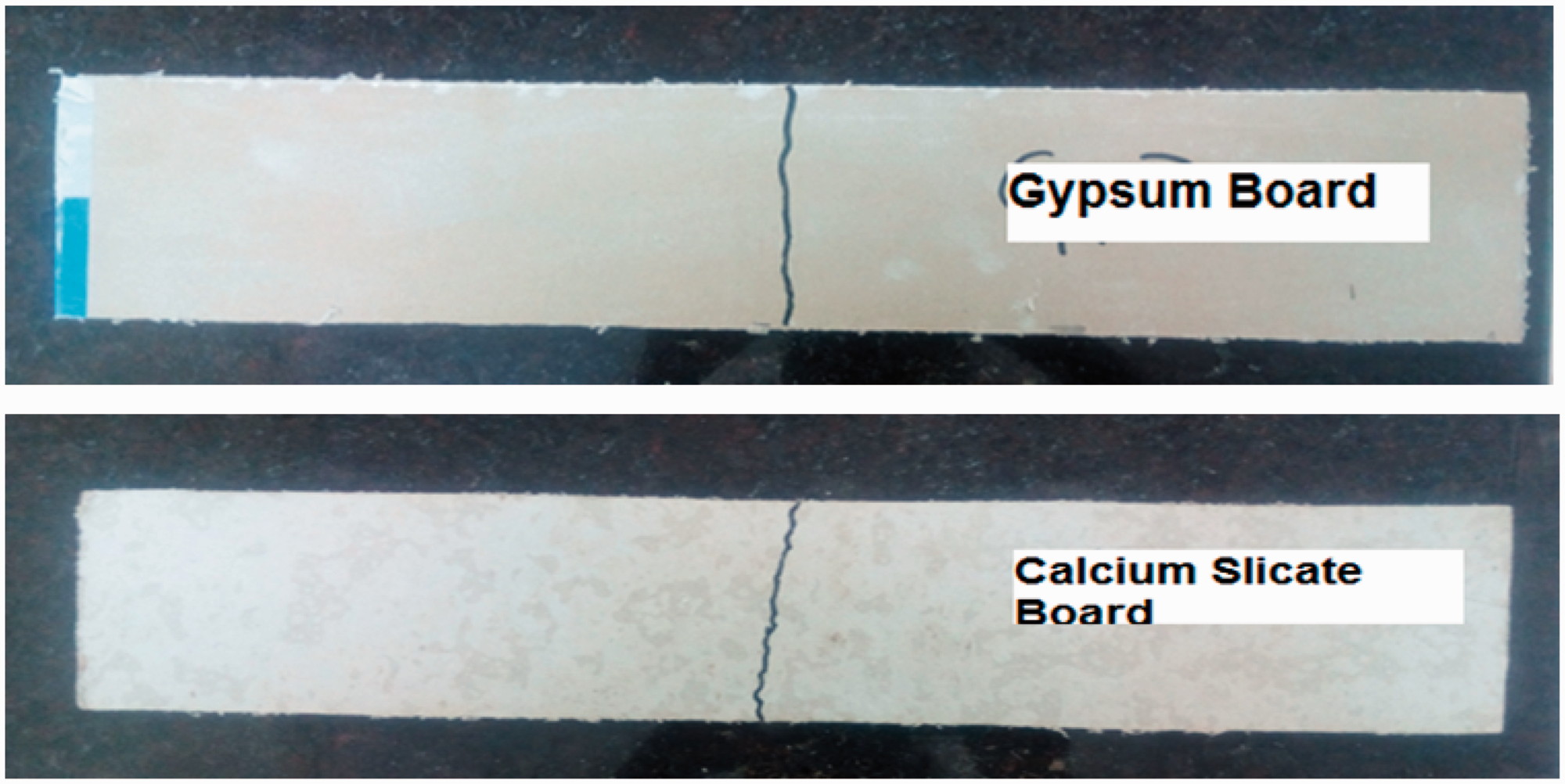
Failure pattern of gypsum and calcium silicate boards at the bottom.
The crack pattern of gypsum core 3 and 4 layers TRC skin may be related to the bond between the core and TRC skin. The bond between the core and the TRC skin is adopted by using the cementitious binder system. In the gypsum core system experienced a less number of crack pattern predominantly a single crack occurred in top TRC skin and transferred to the core and the bottom TRC skin is debonded to a certain length. Similar crack pattern was observed in all the three specimens irrespective on number of fiber layers in the TRC skin. The failure pattern of gypsum core TRC sandwich panel is typically a shear failure of the core as seen in Figure 10(a) and (b).
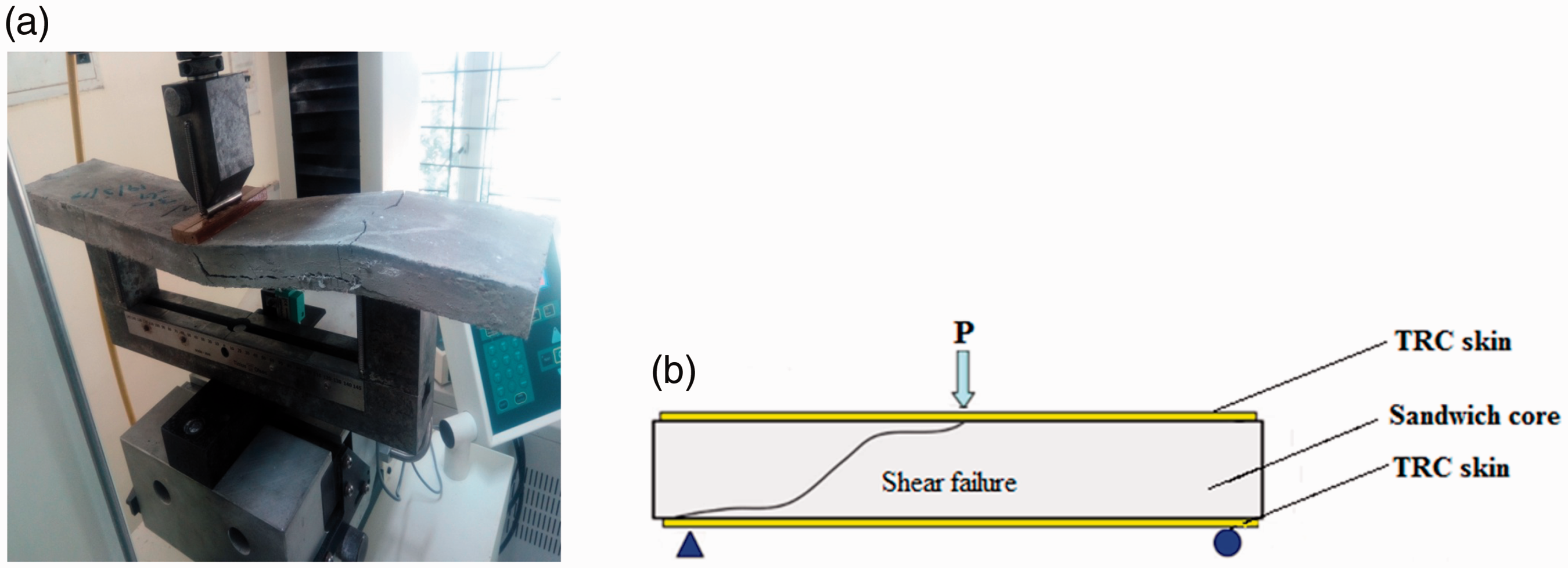
Failure pattern of TRC sandwich gypsum beam. (a) Sandwich beam with gypsum core and (b) schematic of sandwich beam with gypsum core.
In the calcium silicate core TRC sandwich panel experienced denser crack pattern near the loading point as shown in Figure 11(a) and (b). The observed crack patterns are symmetry and spaced equally with respect to the longitudinal axis. The symmetrical crack pattern in calcium silicate panel is due to better bond between the TRC skin and the core. The ultimate failure occurred in the tensile region of the bottom TRC skin and this contributes to the non-linear behaviour.
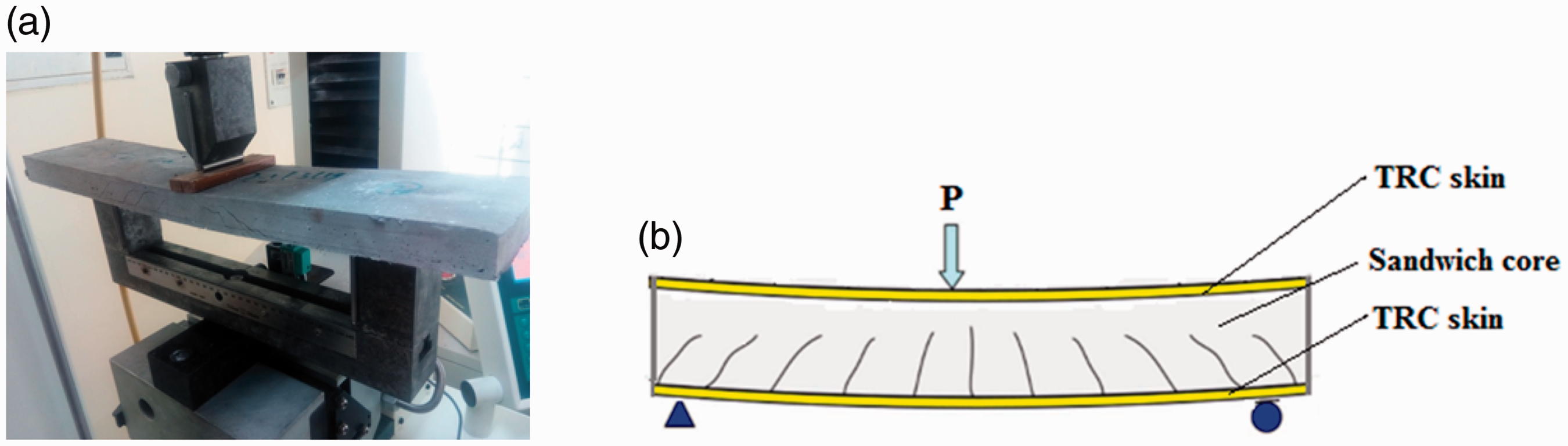
Failure pattern of TRC sandwich calcium silicate beam. (a) Sandwich beam with calcium silicate core and (b) Schematic of sandwich beam with calcium silicate core.
Residual strength and toughness
Using the load-deflection curves, residual strength and toughness values are calculated at first-peak load, peak load, net deflections of L/600 and L/150 and at failure load deflections [12,16]. Residual flexural strengths of 3, 4 and 5 layers TRC skin, fD,n, were calculated for n = 600 and 150 at the corresponding (residual) loads. From Table 4 that the residual strength and toughness value of 3, 4 and 5 layer TRC skin. The residual strength of 4 layers TRC is higher than the 3 and 5 layer TRC skin. The decrease in 3 and 5 layer of TRC does not show any clear dependence on the number of fibre layers. The residual strength at fD,600 for 3, 4 and 5 layer TRC skin is almost same for varying the number of layers and the residual strength at fD,150 for 3 and 4 layer TRC skin is 8.31 and 9.50 MPa respectively. The residual strength at fD,150 is 50% higher than the fD,600 in all the TRC layers. The corresponding toughness value also follow similar trend in all the TRC skin. The toughness value at TD,600 and TD,150 are also same for 3, 4 and 5 layer TRC skin. The toughness value at failure is higher for 4 layer TRC skin compared to the 3 and 5 layer TRC skin. The residual strength and toughness value of 4 layer TRC skin shows increase in the post peak response and increase in load carrying capacity with better bonding between the textile and mortar interlayer.
Residual strength and toughness.
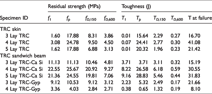
The residual strength and toughness value of calcium silicate and gypsum core with TRC skin sandwich panel is given in Table 4. Residual flexural strengths of 3, 4 and 5 layers TRC skin, fD,n, were calculated for n = 600 and 150 at the corresponding (residual) loads. The toughness of calcium silicate core TRC skin at failure for 3, 4 and 5 layers is 15.19, 30.55 and 31.83 N-m respectively. In the case of gypsum core 3 and 4 layer TRC the toughness value are 21.66 and 8.10 N-m respectively. The reduction in flexural toughness capacity of TRC sandwich beam with 3-layer calcium silicate core is due to the lower saturation of fiber in mortar matrix and the poor chemical bond between the fiber interface; similar behavior reported in literature for various related studies [17–25]. The reduction in flexural toughness in TRC sandwich beam with 4 layer TRC gypsum core may be attributed to higher stiffness of TRC skin leading to brittle failure compared to 3 layer reinforced TRC with gypsum core. The increase in toughness value at failure and the peak load in TRC sandwich beam with calcium silicate core is due to the interlayer bond between the core and TRC skin. The interlayer bond between the core and TRC skin is due its higher stiffness and density. This is attributed to the optimum mortar content in all the textile interlayer leads to increase in deflection and load carrying capacity. From the toughness value and the residual strength results shows that the calcium silicate core performing better compared to the gypsum core panel. It is also indicated that the toughness properties of TRC sandwich beams have been improved with a denser core particularly at higher bending deflections and only influenced on toughness properties at small deflection values as seen in Figure 12.
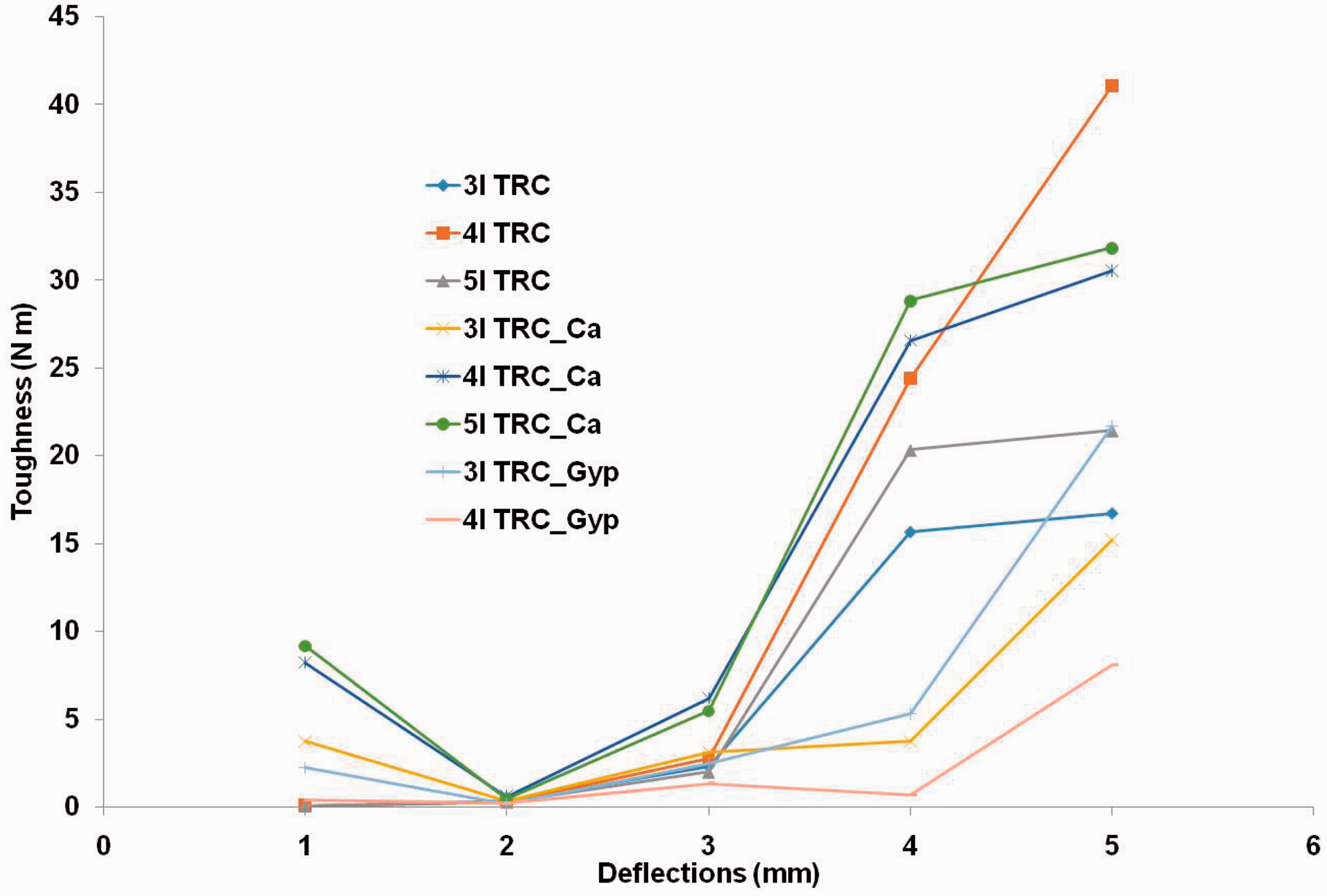
Toughness at salient deflections for various TRC systems.
Conclusions
This paper focused on explaining the bending behavior of TRC sandwich beam with gypsum and calcium silicate panel as core and TRC as skin. From the experimental investigations, the following conclusions were arrived.
The optimal bending response was obtained for 4 layer reinforced TRC specimens both in terms of ultimate load, first cracking load, residual strength and toughness. For TRC sandwich beam with gypsum core, 3 layer reinforced TRC skins performed better whereas in the case of calcium silicate core, 4 layer reinforced TRC skins showed optimal performance. Limit of proportionality for TRC sandwich beam with calcium silicate core is almost same irrespective of the number of layers of textile in TRC skin. Modulus of rupture value is higher for TRC sandwich beam with 4 and 5 layers of textile in TRC and calcium silicate core, the density of the core tends to alter the behaviour of TRC skin in tension face. From the toughness value and the residual strength results shows that the calcium silicate core performing better compared to the gypsum core. The toughness properties of TRC sandwich beams have been improved with a denser core particularly at higher bending deflections. The bond between the gypsum core and TRC skin is not effective due to the shear failure. The increased core density in calcium silicate beam resulted in an increased shear transfer within the core, as well as more effective bond of the TRC skin. The failure of mode of gypsum panel is brittle in nature whereas that of calcium silicate panel is controlled failure. If the core thickness is increased, the delamination of the core with skin requires additional mechanical anchoring system for the load transfer. In such cases, the effect of increasing the number of layers in TRC skin is not recommended. Present study also indicates the importance of developing separate guidelines for toughness estimation of TRC systems, since the salient deflection points suggested in ASTM for which toughness needs to be calculated under estimate the performance characteristics of this material.
Footnotes
Acknowledgements
Authors thank Ms. R. Priyanga, Project student, CSIR-SERC for the help rendered during the conduct of experiments.
Declaration of conflicting interests
The author(s) declared no potential conflicts of interest with respect to the research, authorship, and/or publication of this article.
Funding
The author(s) received no financial support for the research, authorship, and/or publication of this article.