
Abstract
Mechanical performance of 3d-printed polyamide sandwich beams with different type of the lattice cores is investigated. Four variants of the beams are considered, which differ in the type of connections between the elements in the lattice structure of the core. We consider the pantographic-type lattices formed by the two families of inclined beams placed with small offset and connected by stiff joints (variant 1), by hinges (variant 2) and made without joints (variant 3). The fourth type of the core has the standard plane geometry formed by the intersected beams lying in the same plane (variant 4). Experimental tests were performed for the localized indentation loading according to the three-point bending scheme with small span-to-thickness ratio. From the experiments we found that the plane geometry of variant 4 has the highest rigidity and the highest load bearing capacity in the static tests. However, other three variants of the pantographic-type cores (1–3) demonstrate the better performance under the impact loading. The impact strength of such structures are in 3.5–5 times higher than those one of variant 4 with almost the same mass per unit length. This result is validated by using numerical simulations and explained by the decrease of the stress concentration and the stress state triaxiality and also by the delocalization effects that arise in the pantographic-type cores.
Introduction
Sandwich structures with lightweight lattice cores attract a lot of attention during last 10–15 years. Such structures have high specific stiffness and strength, low transverse thermal conductivity and can be used in the multifunctional applications [1–5]. Manufacturing of the lattice cores is somewhat more difficult than the standard ones (honeycombs, corrugated cores, etc.) and it is usually produced by using three-dimensional printing, especially for the small scale structures [5–8].
A lot of variants of the lattice core geometry (pyramidal, hourglass, auxetic, Kagome structures, etc.) have been suggested for the sandwich shells, panels and beams [1–3,9–11]. Impact strength of sandwich structures with lattice cores have been intensively investigated and compared with other type of the cores (see, e.g. [5,6,11–15]). Notably, that the localized loading (considered in the present paper) is one of the most complicated loading case for the sandwiches with the lattice cores, since there are many unsupported areas of the face sheets in such structures [3,11].
Previous investigations were concentrated mostly on the studies and optimization of the core lattice geometry. Optimal design approach for the sandwich panels with pyramidal, tetrahedral, Kagome and X-type lattice cores under uniform thermal loading have been developed in Ref. [16]. Design variables in this study were the hight of the core, the thickness of the beams in the core and the thickness of the face sheets. Minimum density design with prescribed constraints on strength and stiffness for the tetrahedral truss cores have been presented in Ref. [17]. Inclination angle of the beams in the core and their thickness were the design variables in this study. Additional nodal truncation parameter for the tetrahedral truss cores have been considered in Ref. [18] to obtain an optimal structures under compression and shear. Multi-layered pyramidal lattice cores have been investigated in Ref. [19], where it was shown that the local buckling performance of such structures is always less than those one of the single-layer lattices. Topology optimization-based approach was proposed in Ref. [20] to chose the optimal shapes of the curvilinear elements of the functionally graded lattice cores. Hourglass trusses for sandwich structures with improved buckling performance have been proposed in Ref. [21]. Kagome and atomic-type lattices have been compared in Ref. [22] and it was shown that the former has the higher strength and the energy absorption capacity for the same density.
The novelty of the present work is that we investigate the influence of the type of connections that can be used inside the lattice cores. Usually, the lattice cores are made of intersected beams (or narrow plates) that are continuously joined to each other or welded at the points of intersections (see, e.g. [2,6,7]). Such types of connections provide the transfer of resultant forces and moments between the beams inside the lattice structure, which mechanical behavior can be characterized then as the space frame. In the present paper we use such types of connections (continuous joint or welded) and also we consider additional variants of possible joints. Namely, we consider the hinge-type connections that do not transfer the bending moments between the lattice elements. Also, as the limit case, we consider structures without internal joints, such that the lattice elements are connected only to the face sheets and do not joined to each other.
The idea about the change of the type of connections in the lattices comes from the recent works, where the so-called pantographic mechanical metamaterials were proposed [23–26]. It was shown that such structures, made of several families of the parallel beams joined by the hinges with pivots [23], can demonstrate the unusual mechanical behavior with large reversible deformations [23,27,28] and high toughness [23,29]. Dynamic behavior of the pantographic metamaterials have been investigated recently in [30,31].
Thus, in the present study we propose to use the pantographic mechanical metamaterials as the cores of sandwich structures. We evaluate the influence of the rigidity of connections inside the core (stiff – hinges – absence of joints) on the static and dynamic strength of sandwich beams. Note, that the structures with stiff connectors and without it can be also related to the pantographic-type cores with a very high or with very low stiffness of the pivots.
The main result of the present study is that the pantographic-type cores can be very attractive for the dynamic applications. They provide the increase of the material’s impact strength and the energy absorption efficiency in comparison with standard geometries of the lattice cores. Nevertheless, in the static tests the standard geometry become preferable. Explanation of these effects are given in this paper based on the numerical simulations. Change of the type of stress concentration in different cores is characterized by the stress state triaxiality factor, which becomes lower in the pantographic-type cores.
Experimental
Materials, geometry of samples and 3d-printing
Experimental samples were manufactured by using SLS 3d-printing system EOSINT P395 (EOS, Germany) with Polyamide 12 powder. Resulting material called PA2200 (according to EOS classification) is the 3d-printed variant of the nylon polymer with added white pigment. This material and its modifications are widely used in different applications in the aerospace and mobility sectors, in package systems, etc. [32,33]. PA2200 usually has of about 10% of porosity for the standard printing regimes recommended by the equipment manufacturer.
Sandwich beams of the length 140 mm and hight 45 mm were printed. Width of the face sheets was 15 mm and its thickness was 3 mm. Four variants of the lattice cores were considered (Figure 1). All of these cores are formed by the inclined beams with square cross sections with dimensions 4 × 4 mm. In the printed samples the inclination angle of the beams in the core was ±45 degrees (intersection angle is 90 degrees). The variants of the core 1, 2 and 3 are related to the so-called pantographic structures. These cores are consisted of two families of the beams lying in two parallel planes. All beams from the same family have the same inclination angle that is +45 or -45 degrees, respectively. Distance (gap) between the beams from different families was 0.6 mm. This is the smallest value of the gap that guarantees the absence of the over-melting effects [34] during 3d-printing. Beams from different families are connected to each other at the points of their intersections.
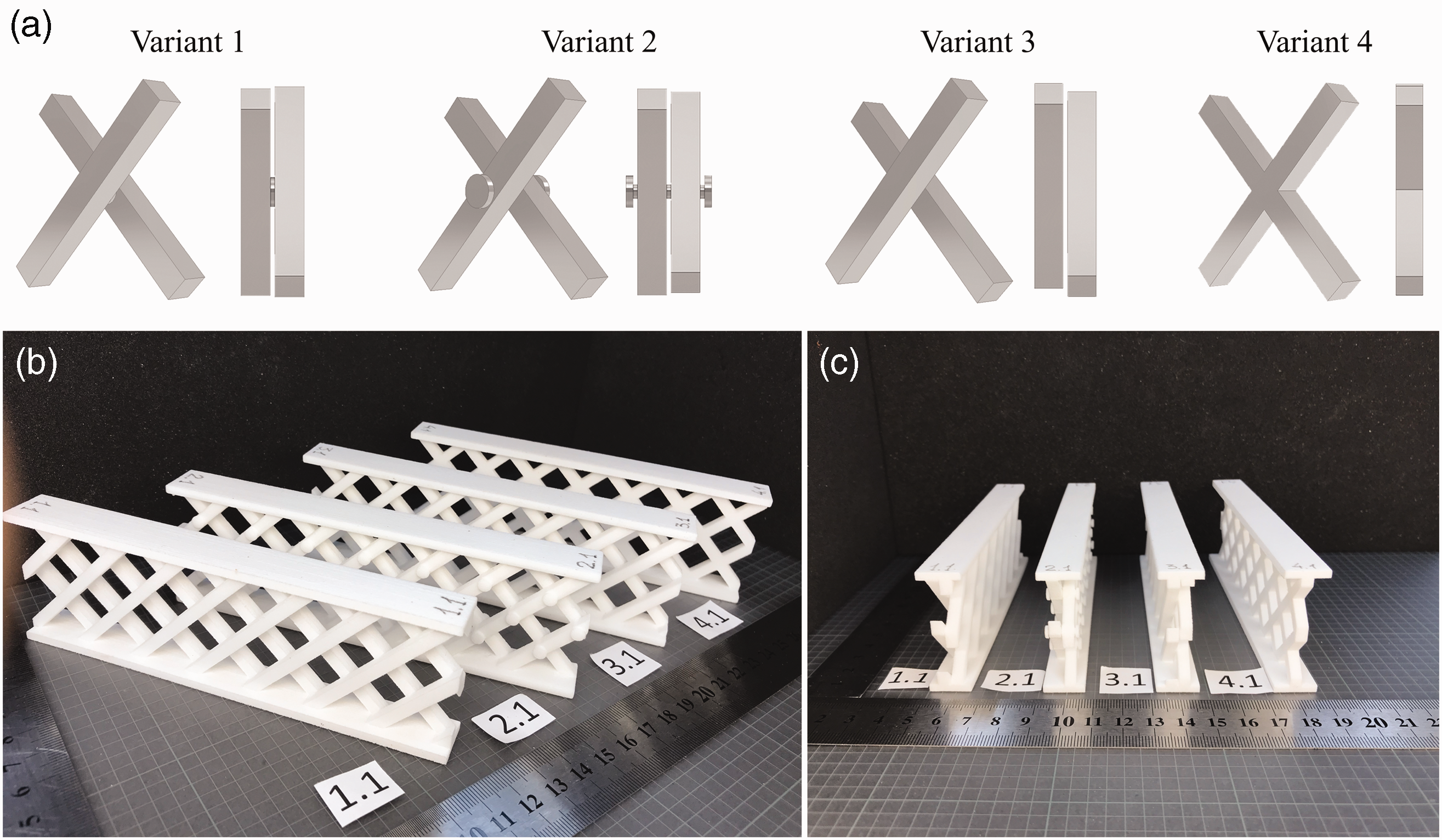
a: Variants of connections between the beams in the lattice cores used in the experiments (1 – stiff connection, 2 – hinges with pivots, 3 – absence of connection, 4 – single-layer lattice core). b, c: Examples of 3d-printed sandwich beams (b – 3d view, c – side view). Variants 1–3 have the pantographic-type two-layered structure of the lattice core.
Type of connections used in the lattice cores are shown in Figure 1(a). At the intersections in variant 1 we use the short stiff connectors made of solid material that joins together the beams from different families. Such connection provides the transfer of the resultant forces, bending moments and torque between the connected beams. In lattices of variant 2 we gave an additional degree of freedom for the joints and made it with hinges and pivots. Such geometry of the lattices can be recognized as the standard pantographic metamaterial [23]. Diameter of the hinges’ holes was 3.2 mm, diameter of the pivots was 2 mm, length of the pivots was 9.8 mm. Pivots are ended with the hats which diameter was 4.5 mm. All elements of the core were printed simultaneously with other parts (i.e. we have nondetachable connections). Variant 3 of the core do not have the connections between the beams in the core (see Figure 1(a)). In this variant elements of the lattice core are attached only to the face sheets. Variant 4 is the single-layer lattice formed by the inclined intersected beams lying in the same plane. These beams are continuously joined to each other.
Note, that in the pantographic-type lattices (variants 1–3) we have some kind of structural anisotropy due to non-symmetric placement of the beams in the core with respect to the sagittal plane. As the consequence, during in-plane loading of these lattices there arise the out-of-plane deformations and twisting. We remain this anisotropy for the present research since in the single- and two-layered structures we cannot avoid it. For the development of the symmetric structures one should make more layers (at least 4) with symmetric placement of the beams (corresponding structure can be denoted as
Printed samples of sandwich beams are shown in Figure 1(b). Seven similar samples of each type of the beams were printed for the experimental tests (in total, 28 samples). SLS process was performed with standard regimes recommended by the equipment manufacturer. Sandwich beams were oriented in the horizontal plane of the working chamber, such that the built direction was oriented along the normal to the beams’ length and height. Such orientation is most preferable since in the horizontal plane PA2200 has an isotropic properties and the highest stiffness and strength. Some decrease of mechanical properties is realized in the built direction that is not important for the considered types of samples and testing schemes and it was neglected in the analysis. Residual distortions of the samples after manufacturing were not observed visually.
Printed samples have almost the same mass, though the mass of the variant 4 is slightly lower than the others. Namely, sandwich beams had masses
Experimental procedures
Experimental tests were performed for the localized type of loading according to a three-point bending scheme. This scheme is widely used for characterization of sandwich structures under static and impact loading both and it can be easily performed by using standard equipment. Moreover, the three-point bending scheme provides the concentrated type of loading, which is very important to check for the lattice cores that do not provide the full supporting of the face sheets (except this is a foam filled lattice cores, see e.g. [36]). Span size in the static and dynamic tests was 40 mm, such that the span-to-thickness ratio was ∼0.9.
Static tests were performed for the four samples of sandwich beam with different type of the core using Instron 5969 machine (Figure 2(a)). In the tests, samples were placed symmetrically on the supports and loaded at the center by the loading nose. The radii of the loading nose and supports were 5 mm and 2 mm, respectively. Crosshead speed in the tests was 1 mm/min. Deflections of specimens were measured through the displacements of the crosshead. Compliance correction of the testing machine was performed according to ASTM D 790. Load/deflection curves were registered until the 60% drop of the load or until the full compression of the lattice core.
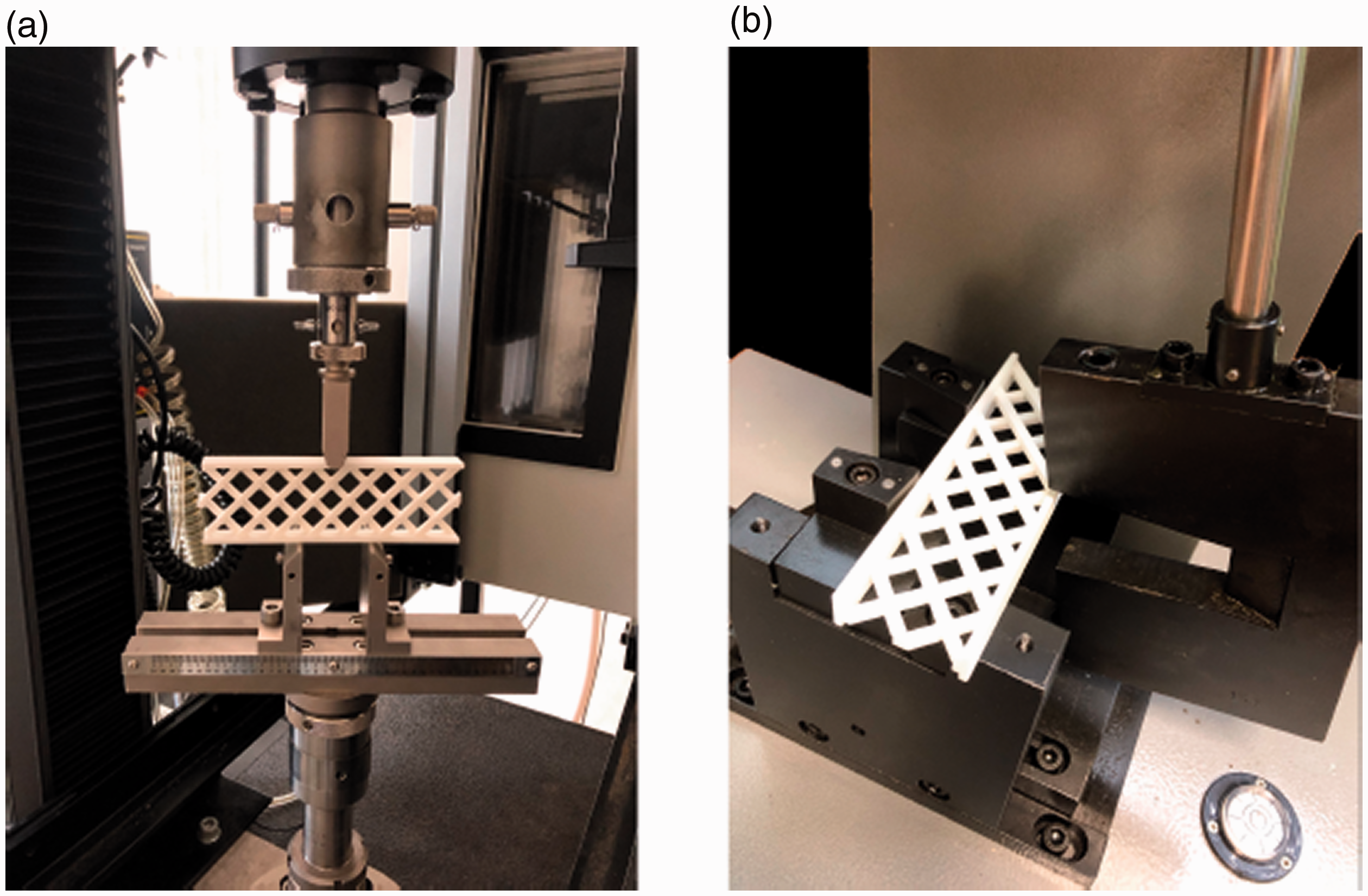
a: Quasi-static three-point bending test, b: Impact test.
Deformations of samples under the quasi-static loading were additionally investigated by using digital image correlation (DIC) analysis. Black and white pattern was created on the samples surface by using spray paints. Images of the lateral surface of the samples were obtained during tests by using 24-megapixel camera Nikon D5500. Digital Image Correlation Engine (DICe) software was used for the processing of images and evaluation of distributions of the Green-Lagrange strain. Visualization of DIC results was done using Paraview software.
Impact strength and energy absorption efficiency of samples were measured by using Charpy impact testing equipment (ASTM D 6110, Figure 2(b)). Samples were placed horizontally on the supports of testing machine and broken by a swing of the pendulum. Initial energy of impact E0 was defined by raising the pendulum to the prescribed angle. Six tests with sandwich beams of the same geometry were performed increasing the impact energy in the range 5.4…20 J. Value of the absorbed energy E was estimated by using formula
To evaluate the failure regimes of the samples under the impact we used the high-speed camera VideoSprint (Videoscan, Russia) with the frame rate 1000 fps and with 1280 × 500 resolution.
Simulations
Experimental results for the impact tests were compared to the finite-element simulations. For the 3d-printing and for the simulations we used the same three-dimensional models of the samples. Impact test was modelled using explicit dynamics solver Ansys LS-Dyna. Modelling was performed for the time period from the beginning of the contact between the pendulum and the sample until the full breakage of the last one. This time period was of about 0.015…0.025 seconds for all type of the samples that is correlated with experimental data (duration of the samples failure was evaluated based on the video from the high-speed camera).
Rigid behavior was assigned for the steel supports and loading nose since their elastic modulus is much higher than those one of PA2200. To reduce the number of degrees of freedom we modelled only the external surfaces of the supports and of the loading nose that come into a contact with the sample elements (Figure 3). Full mass of the pendulum Mp was taken into account by attaching the point mass to the finite-element model of the loading nose.
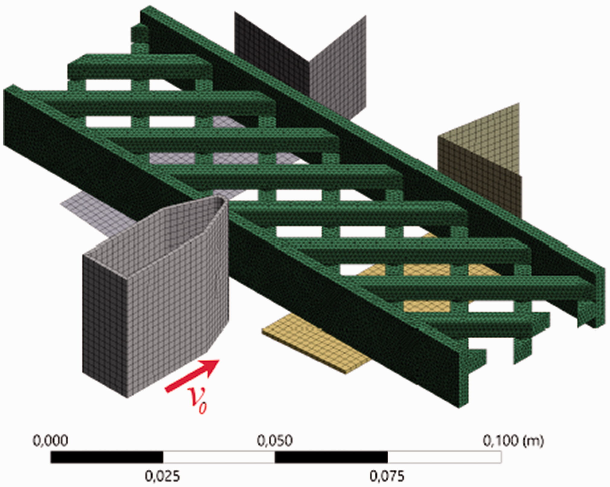
Example of the finite element model for the impact test.
In the initial conditions we prescribed the velocity of the loading nose in the normal direction to the surface of the beam face sheet. Value of this velocity v0 was evaluated based on the known energy of impact E0 as
Standard linear tetrahedral elements (type TET13, 4-node explicit dynamic element) recommended by Ansys for the impact test were used. Size of the finite-elements was defined by the mesh seed equals to 1 mm. Total number of the nodes and of the elements was of about
To define the elasto-plastic behavior of PA2200 we used the Young’s modulus value 1.3 GPa, the Poisson’s ratio 0.35, yield strength 50 MPa and tangent modulus 100 MPa. Note, that these properties are close (but lower) to those one of the standard explicit material Nylon from the Ansys library. Nylon has similar composition as PA2200, however, it is a dense (without porosity) high-strength material used, e.g. in the fiber-reinforced composites.
The main feature was the definition of the failure criterion that allows elements to fail during the simulation. From the preliminary tests we found that the standard criteria such as maximum plastic strain, maximum shear stress criterion, or the maximum principal stress/strain criteria do not allow to describe the obtained experimental results for the impact strength and for the failure modes of the samples under dynamic loading. All of these criteria lead to the predictions of the highest impact strength of sandwich beams of variant 4 that contradicts with experiments, in which this variant was the weakest under the impact. The same result was obtained by using the Johnson-Cook criterion with the strain rate effects. Finally, we found that the appropriate results can be obtained by using the so-called maximum tensile pressure (MTP) criterion that defines the material’s hydrodynamic tensile limit (i.e. the limit for the first invariant of the stress tensor). Notably, that this criterion is recommended by the Ansys library for the standard explicit material Nylon. We can also refer to the works [37,38], where the criterion for the first invariant of the strain tensor (related to pressure under conditions of relatively small deformations) was used for the failure analysis of the polymer materials.
The standard value of MTP criterion for structural Nylon in Ansys is very high (1 GPa). In the present case we have much weaker material obtained by 3d-printing and it contains porosity. Adjusted value of the failure criterion was of about 52 MPa. This value allowed us to describe correctly the impact strength as well as the failure modes of the samples under the impact.
Static tests were not modeled since their results are well understandable and can be interpreted based on the intuitively clear arguments. In the static tests we obtained the highest rigidity and strength for the single-layer sample of variant 4. This type of the samples has the fully symmetric structure. From the mechanics of composites it is known, that in comparison with the other type of possible anisotropic structures the symmetric structures (e.g. the laminates with symmetric stacking of the plies) have the highest apparent stiffness and strength [39]. Here we have the same effects but at the macro-scale level of structural anisotropy. Two-layered pantographic cores (variants 1–3) have some additional out-of-plane deformations under the in-plane loading that leads to the reduction of their rigidity as well as the load bearing capacity in the static tests. The situation becomes different for the dynamic tests and explanation of these dynamic effects was the subject of the performed simulations.
Results and discussion
Static tests
Obtained load–deflection curves for the static tests are shown in Figure 4(a). It is seen, that the maximum load-bearing capacity, rigidity and toughness are realized for the single-layer lattices of variant 4 (red line in Figure 4(a)). As it can be expected, variant 1 has the highest static properties among other pantographic-type lattices (blue line in Figure 4(a)). In this variant we used the stiff connectors. Hinge-type connectors in variant 2 provide the lowest rigidity and the lowest static strength of the beam. During loading of this beam there arise a lot of damage around the hinges that results in the load drops that are seen in the plotted curve (orange line in Figure 4(a)). In variant 3 we obtain typical curve for the large non-linear deformations of the lattice, in which the first maximum of the load is related to the local buckling and the second maximum is related to the total compression of the lattice core.
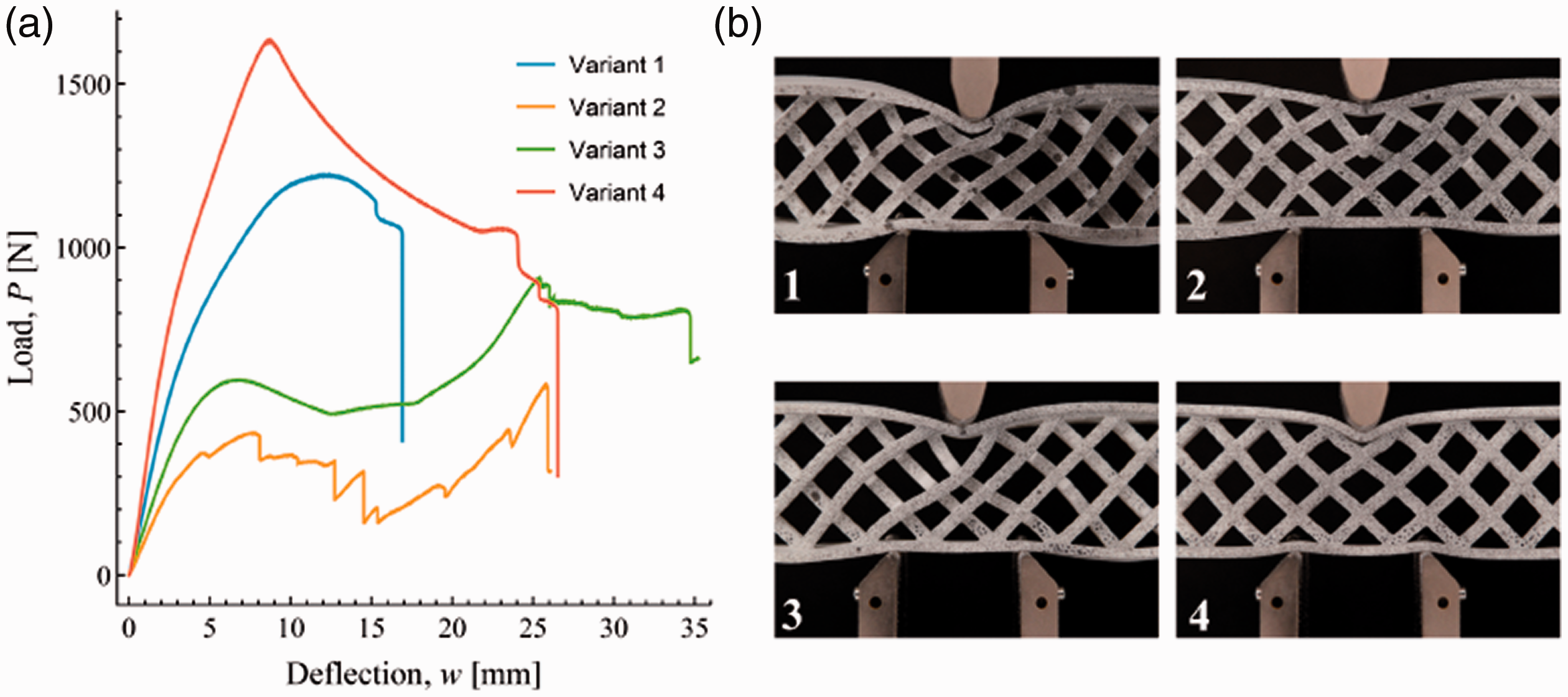
a: Load–deflection curves obtained in the quasi-static three-point bending tests for different variants of sandwich beams, b: Deformed state of different variants of the beams at the first maximum of the load (variants numbers are marked on the images).
In Figure 4(b) we show the deformed state of the sandwich beams at the maximum loading level. For the variants 2 and 3 this is the first maximum for the level of deflections of about 7 mm (see Figure 4(a)). Given images illustrate the type of the failure modes that are realized in different cores. In variant 1 the maximum loading level arises when the intensive plastic deformations are developed in the face sheets and in the core of the beam. In variant 2 there arise the first observable damage in the central hinge placed under the loading nose. In variant 3 there arise the local buckling in the core. In variant 4 the failure is principally different from the others and here we have the beginning of the global out-of-plane buckling. This buckling process is not catastrophic and the sample of variant 4 loses the stability in controllable manner with further movement of the loading nose.
From the comparison of the images in Figure 4(b) it is seen, that in the pantographic-type cores (variants 1–3) the amount of the deformed elements is much higher then those one in variant 4. To clarify this result in Figure 5 we show the DIC analysis for the beginning of the static tests at the small deflections level w = 2 mm. This moment of the loading corresponds to the global linear behavior of the structures (see curves in the Figure 4(a)). In Figure 5 we show the distribution of the strain energy density that was evaluated based on the measured strain state of the beams in the DIC analysis. Strain energy density was estimated in a plain strain approximation as
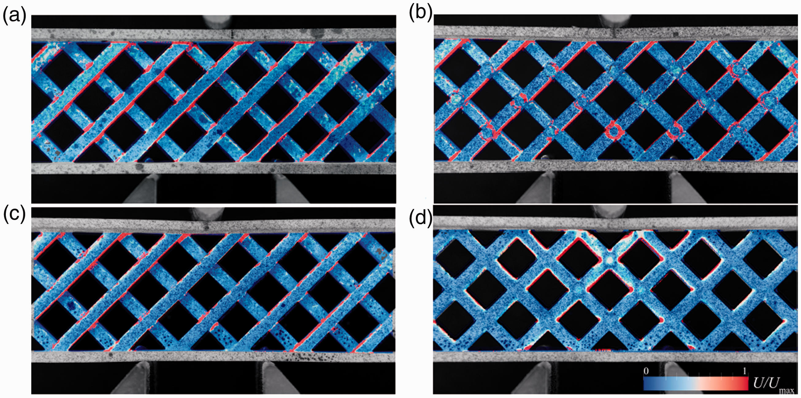
Distribution of the normalized strain energy density in the core of the sandwich beams evaluated based on the DIC analysis. Loading level corresponds to the deflections value w = 2 mm. Variants of the core: a - 1, b - 2, c - 3, d - 4.
In Figure 5, there arise three typical levels of the strain state intensity that are colored with red, white and blue colors. Red color corresponds to the high concentration of the strain energy and intensive deformations. Red color arises at the intersections of the beams in variants 1, 2 and 4 (Figure 5(a), (b) and (d)). Typical local concentration of the strain energy at the sharp corners in the variant 4 is well seen. We also observe the thin red strips along the beams surfaces in the lattices that may arise due to their bending. Such bending-type effects are very long in the pantographic lattices (variants 1–3) and the red color covers almost the full surface of the beams from the upper to the lower face sheet. In variant 4 such type of coloring arise mostly under the loading nose (at the top of the sample center). The white and blue color in Figure 5 corresponds to the middle and low level of the strain energy density, respectively. And it is well seen that in the pantographic-type lattices (Figure 5(a) to (c)) we have much more uniform distribution of the these colors over the lattice. In variant 4 the strain energy is primarily concentrated under the loading nose and between the supports (Figure 5(d)). For variants 1–3 we can even observe the slight increase of the strain energy level outside from the supports (see the increase of the amount of the white color on the left and right sides of the images in Figure 5(a) to (c)).
Thus, we can conclude that in the pantographic cores (variants 1–3) we have some kind of delocalization effect in comparison with the standard plane geometry of variant 4. The strain energy density in these structures is distributed over the large amount of the elements that work mostly in bending and their deformations are spread far away from the points of application of the external loads. Thus, the pantographic-type cores can be recognized as “bending-dominated” [40]. Such type of structures are well known for their high performance in the dynamic applications [40–42]. As we have shown, its static performance is not very high in comparison with the plane lattice of variant 4. However, in the last one we have the strong strain concentration effects. This concentration does not make a significant influence in the static test, since PA2200 material is rather ductile. However, as it is shown in the next section, such concentration effects become a serious problem for the impact loading.
Impact tests and simulations
Found dynamic properties of the sandwich beams are presented in Figure 6. In Figure 6(a) we show the values of the impact strength found in the experiments and in the simulations. These results are correlated (Pearson correlation coefficient 0.952, P-value 0.048) and the weakest variant of the samples is the fourth variant. In the experiments the highest impact strength had the samples of variant 1 (with stiff joints in the core). In the simulations there arose some inaccuracies and we found that the highest performance should have the variant 3 (without joints). These inaccuracies can be the consequence of the errors in the definition of the material properties. Experimental data for the high strain rate behavior of PA2200 is not fully available at that time and should be clarified in the future work. Nevertheless, from the point of view of the absolute values, variants 1 and 3 have almost the same impact strength (
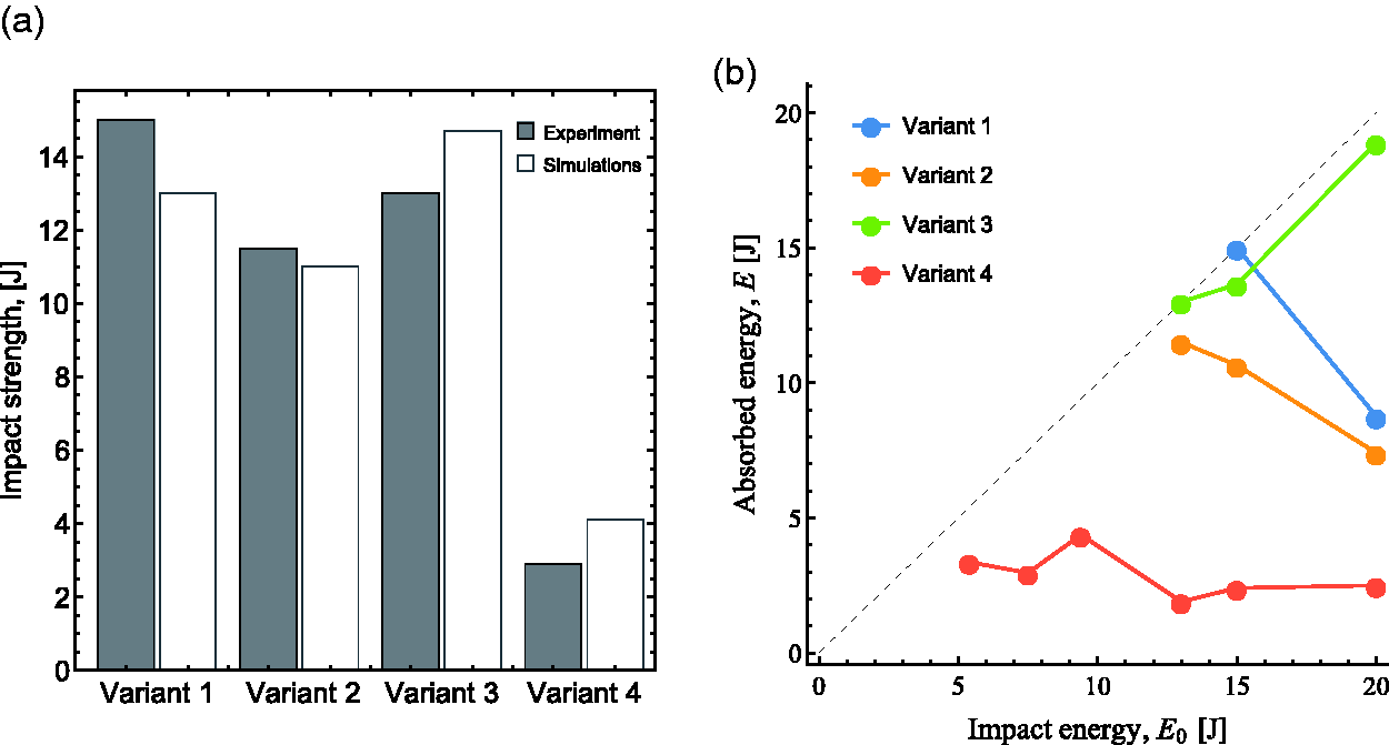
a: Impact strength of the sandwich beams found in the experiments and in the simulations; b: amount of the absorbed energy found in the experiments for the samples of different type.
In Figure 6(b) we show the full data of the dynamic tests for the range of the impact energy 5–20 J. We show here the found values of the absorbed energy E for different samples that were tested with different initial energy E0. Black dashed curve is the bisectrix in this plot, which show the possible maximum level of the absorbed energy (the sample cannot absorb the larger amount of the energy than the pendulum had before the impact). Plotted curves in Figure 6(b) are started at a point, which correspond to the first full breakage of the sample of the certain type. Such point for the variant 4 arise at the lowest energy level, because these samples were broken even at
Several sandwich beams after the impact tests are shown in Figure 7. One can see the difference that arise in the failure modes of these samples. The interesting feature of variant 1 (stiff joints in the core) is almost the same shape of the damaged area for different values of the impact energy. In opposite, in variants 2 and 3 the damaged area becomes larger with increase of the impact energy. Notable peculiarity of variant 2 is the relatively large amount of the broken elements even in the case of the total absorption of the impact energy (see variant 2 for
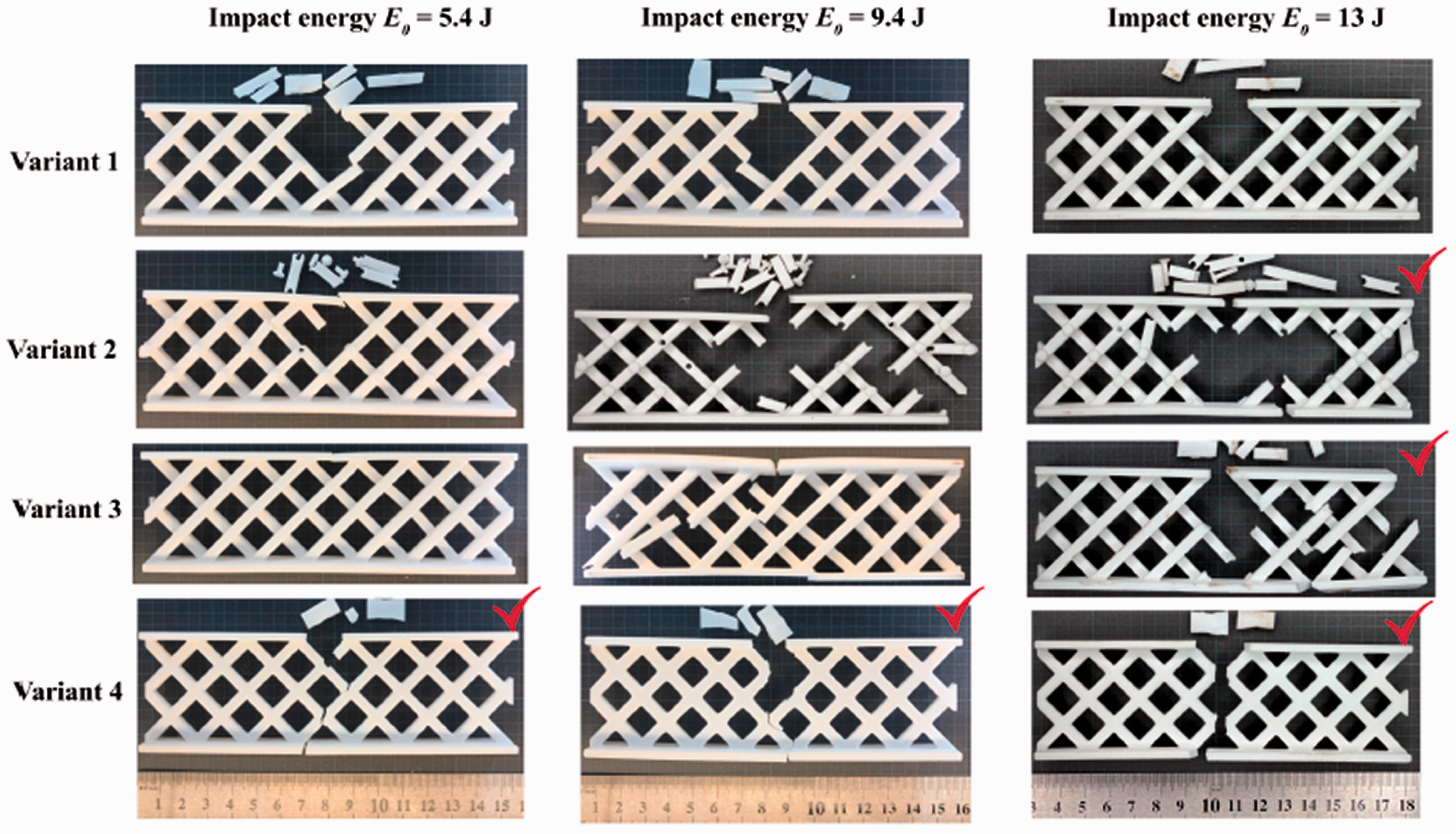
Sandwich beams with different variants of the core after impact tests. Fully broken samples are marked with red notes.
The main difference is seen for the samples of variant 4 in Figure 7. These samples with plane geometry of the core have a very small damaged area and a single crack across their core. In the impact tests these samples had the lowest energy absorption efficiency (see Figure 6) and as it is seen in Figure 7 their failure mode can be related to the type of the brittle cleavage. In the pantographic-type cores (variants 1–3) we do not have such effects and their destruction is realized with large amount of the broken elements over the whole body of the sample.
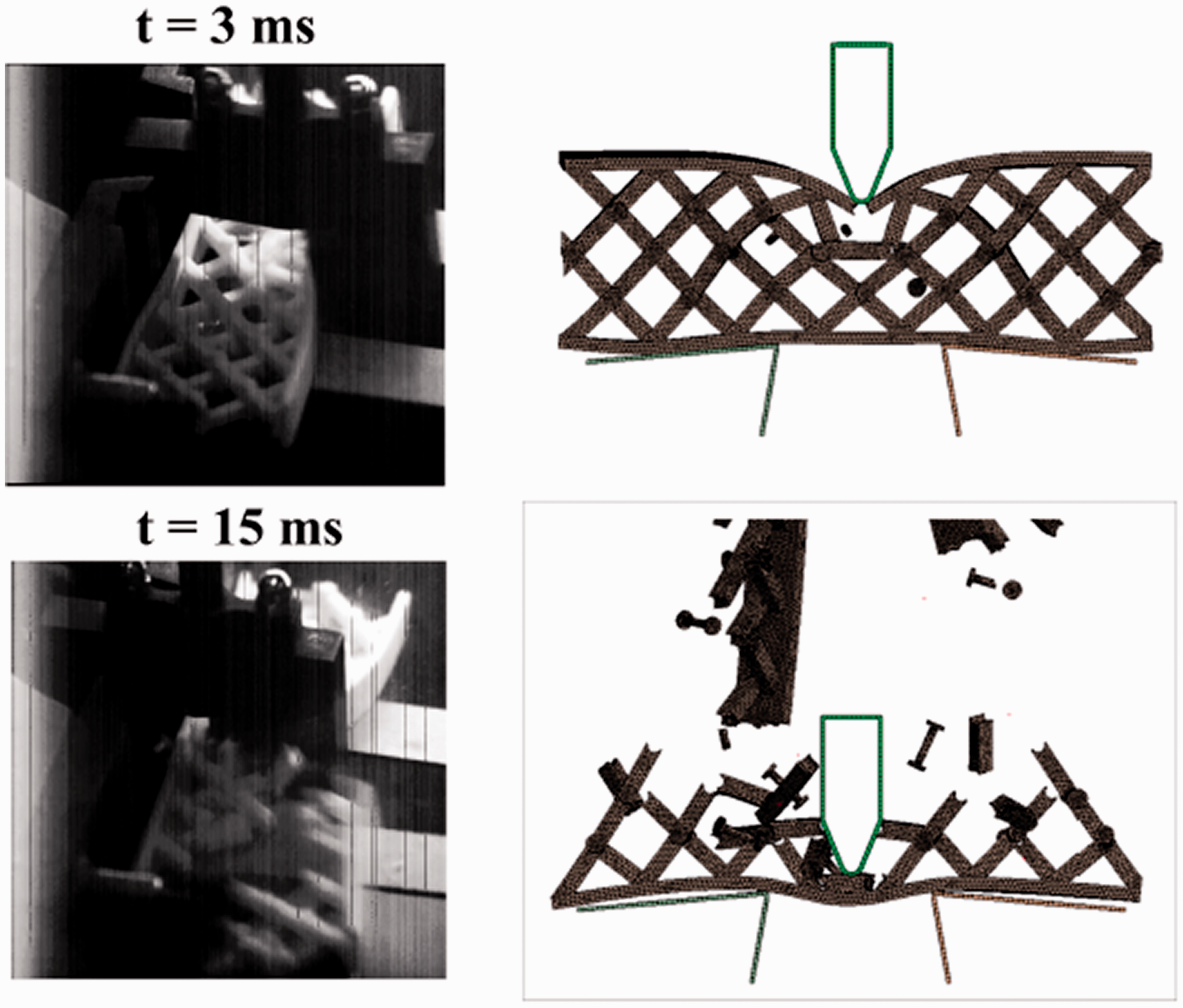
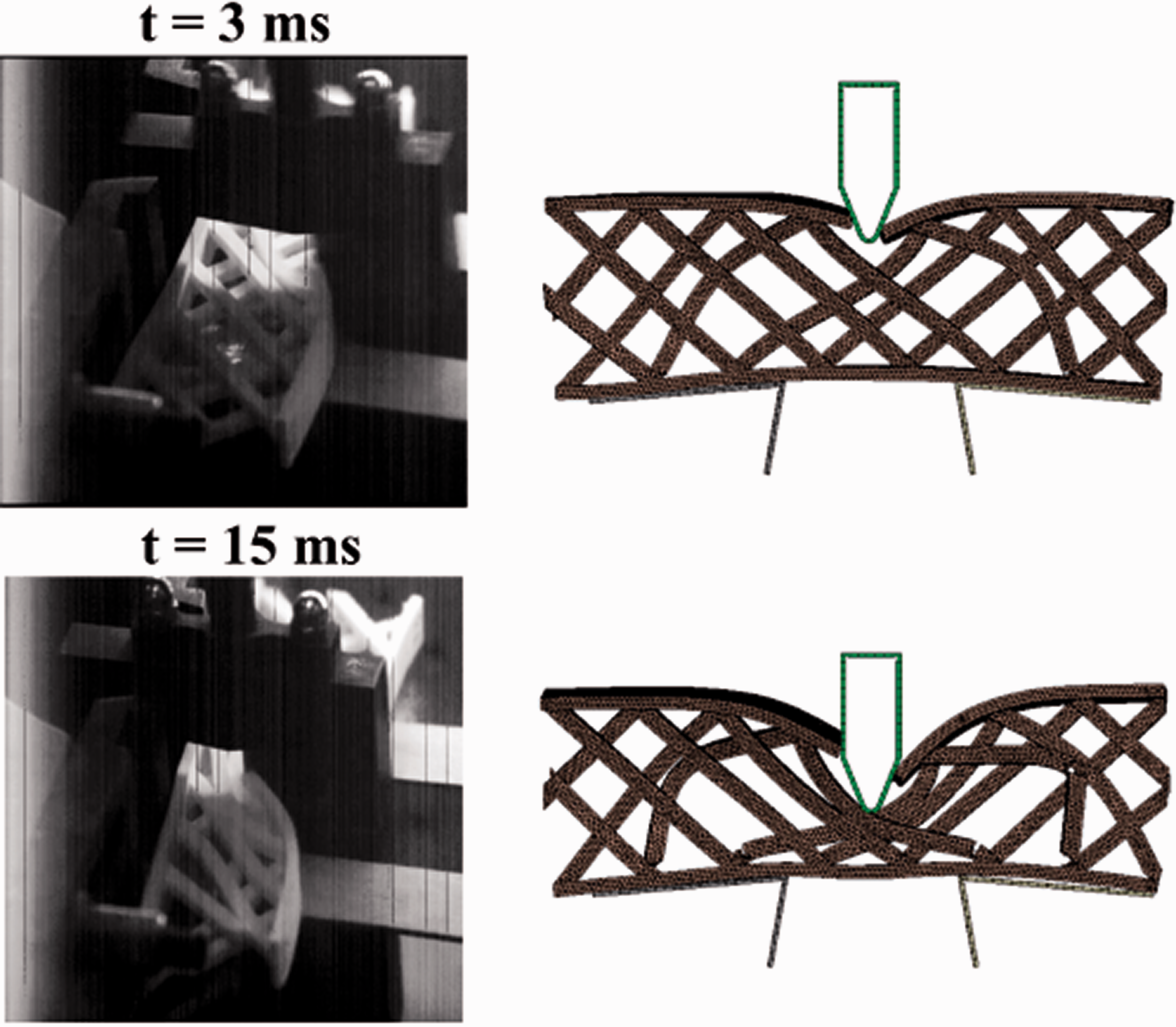
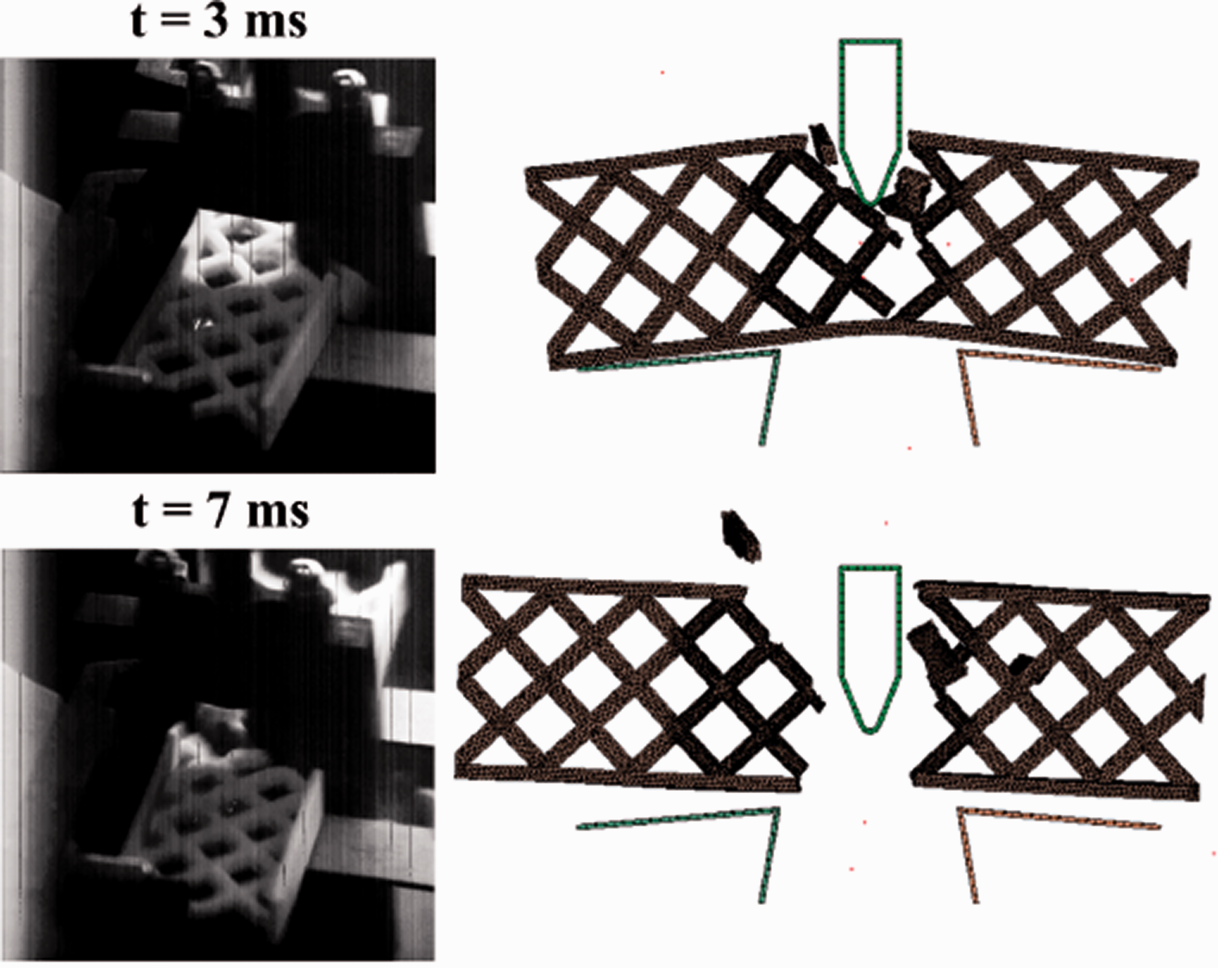
Additional illustrations for the failure modes of different samples under dynamic loading are given in Figures 8 to 11. Here we show the images from the high-speed camera and corresponding simulation results for the impact energy E = 9.4 J.
In the tests that are shown in Figures 8 to 11 the first three variants of the core were not totally broken. However, it is well seen the difference that arise in these cores under the impact. In variant 1, the core was partially broken and the pendulum was stopped inside it at the time moment
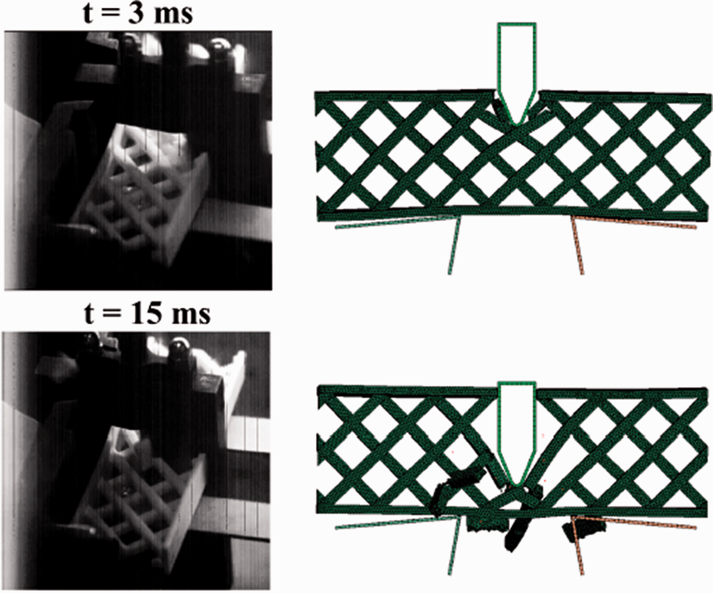
Impact test with the sandwich beam of variant 1. Images from the high-speed camera (left) and simulations (right). Impact energy E = 9.4 J.
Impact test with the sandwich beam of variant 2. Images from the high-speed camera (left) and simulations (right). Impact energy E = 9.4 J.
Impact test with the sandwich beam of variant 3. Images from the high-speed camera (left) and simulations (right). Impact energy E = 9.4 J.
Impact test with the sandwich beam of variant 4. Images from the high-speed camera (left) and simulations (right). Impact energy E = 9.4 J.
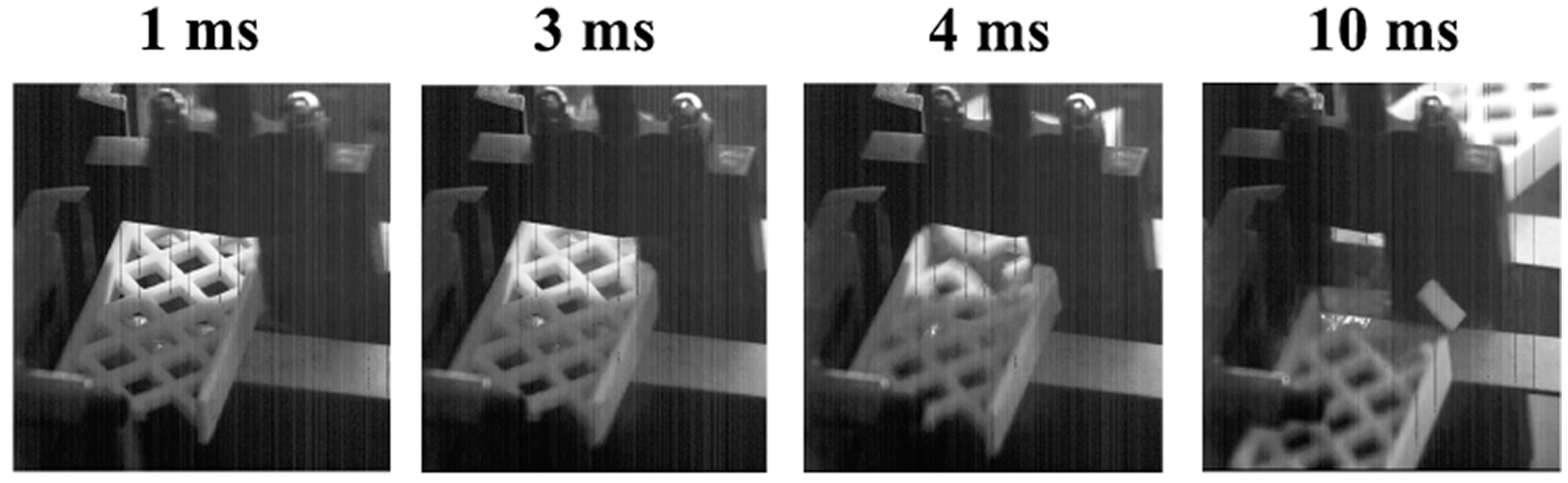
Images from the high-speed camera for the impact tests with the sample of variant 4. Impact energy
In Figures 8 to 11 one can see a good agreement between the experimental observations and simulations for the failure modes of different variants of the core. This agreement (as well as the correspondence for the impact strength in Figure 6) was achieved due to chosen variant of the failure criterion. Using MTP criterion in FE simulations we achieved the brittle failure for the variant 4 of the core and relatively ductile failure with large deformations in the variants 1–3. Using other standard criteria (maximum plastic strain, maximum principal stress, etc.) we obtained the non-correct failure modes, e.g. with the material destruction directly under the loading nose without propagation of a crack in the variant 4 of the beam. Some changes in the material properties (Young’s modulus, yield strength, failure strain, etc.) did not allow us to describe correctly experimental results. Also we checked that the strain rate have the same order in the samples of different variants, such that the strain rate effect cannot be used for the justification of the obtained results for different samples at the same level of impact energy.
Explanation for the higher impact strength of the pantographic-type cores can be given from the point of view of stress concentration effects and in terms of the level of stress state triaxiality.
At first, one can see that the variant 4 of the core with plane geometry contains a lot of internal sharp corners that results in the high concentration effects inside this type of the core (see DIC results in Figure 5(d)). In the other variants 1–3, the sharp corners exist only at the place of connections between the lattice elements of the core and the face sheets. Thus, in these variants the material of the core experienced less level of the stress concentration and the elements of the core can be intensively deformed without fracture. In the present study we used the approximate methods of the failure analysis and we did not perform the fracture mechanics simulations. Nevertheless, the values of the impact strength of the beams and their failure modes were evaluated correctly and we can try to clarify the material behavior in terms of its stress state without evaluation of the stress intensity factors.
Thus, it is natural to evaluate the stress triaxiality since the chosen MTP failure criterion is related to the first invariant of the stress tensor (
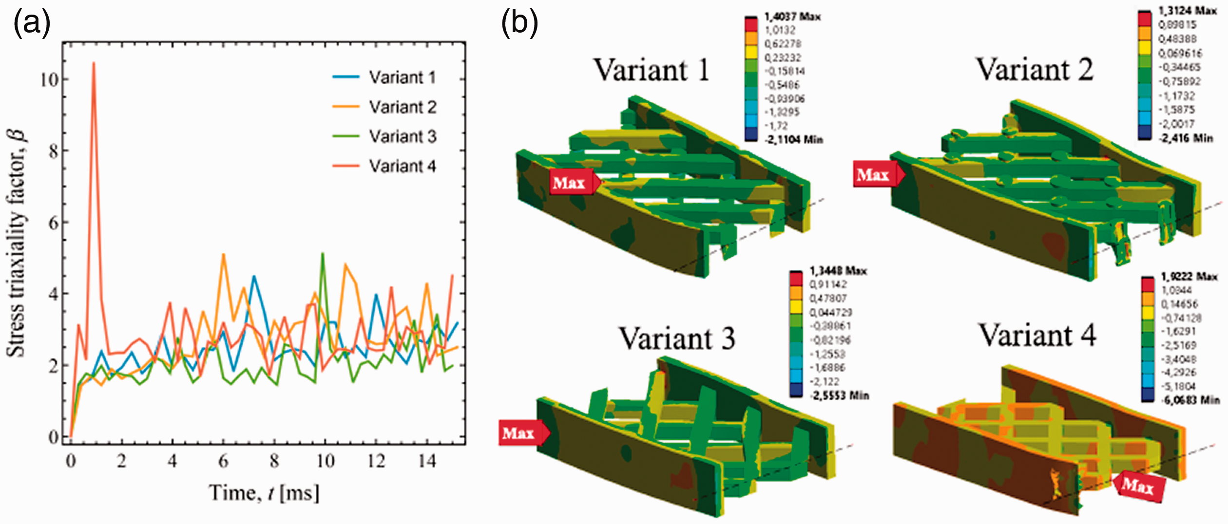
Values of stress triaxiality factor β evaluated numerically for different variants of the samples, a: dependence of maximum value of β (in the whole FE model) on time, b: distribution of β over the half of the samples models and over the central cross section. Movement path of the loading nose is shown by black dashed line.
Thus, the increase of the core strength under dynamic loading can be related to the change of the material state from the high stress concentration under triaxial tension (in variant 4) to the predominant distortions with low triaxiality (in variants 1–3). In opposite, in the static tests the values of the stress state triaxiality can be less important for the ductile materials (see, e.g. [43]), and the load bearing capacity of the core is determined mostly by the global/local buckling effects and the structural stiffness, that is higher in the lattice of variant 4.
Finally, one more comparison of the cores variants can be given in view of the reactions and inertial forces that are experienced by the supports and by the impacter, respectively. In such a way we can choose the most stiff (soft) structures that provide the rapid (prolonged) deceleration of the impacter. This can be an important aspect in different applications, when the protection and safety is mostly needed for the impacter or for the supports. In Figure 14 we show the example of the change of the impacter velocity and acceleration that were found in the simulations. Results are presented for the value of the impact energy
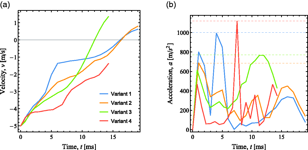
Dependence of the impacter velocity (a) and acceleration (b) on time during impact tests with different sandwich beams. Impact energy
Conclusions
In this work we evaluate the influence of the type of connections that can be used in the lattice core of sandwich structures. We consider the variants of the cores with continuous joints, with stiff connectors, with hinges and pivots and without internal connections. Three last types of the cores can be related to the so-called pantographic mechanical metamaterials with different stiffness of joints between the lattice elements.
We show that the bending-dominated behavior of the pantographic-type lattices leads to the delocalization of the stress state in the core and to the increase of the amount of the material volume involved in the energy absorption processes. Deformations become higher and the damaged area becomes larger in such types of the cores under the impact tests. Due to reduction of the stress concentration and the stress state triaxiality inside the lattice core, the impact strength of such structures become higher. However, in the static tests, the pantographic-type cores demonstrated the worse performance in comparison with the standard plane lattices with continuous joints.
The main features of the considered lattice cores are the following: Variant 1 (stiff joints). Highest impact strength over all variants. Highest rigidity and load bearing capacity among the pantographic-type lattices. Variant 2 (hinge joints). High impact strength. The lowest inertial forces produced during deceleration of the impacter. Variant 3 (absence of joints). High impact strength. Rapid stopping of the impacter. Highest toughness under static tests among the pantographic-type lattices. Variant 4 (continuous joints). Highest performance under static loading.
Note, that some studies with the joints geometry for the lattice cores have been also considered previously in view of the possible increase of the local buckling performance. Namely, such effects were achieved in the hourglass trusses with stiffened intersection zones [21], in the tetrahedral trusses with nodal truncation [18] and in the lattices made of the beams with variable cross-section [7]. The main difference of our results is that we propose not to use the stiffening of the joints, but we change their type such that the lattice structure becomes bending-dominated (i.e. it has lower local buckling performance) and its impact strength increases.
In this work we consider the most simple case of sandwich beams, though the extension of the presented results can be easily done for 2.5 D structures and also it can be generalized for the orthotropic sandwich panels with appropriate modification of the lattices geometry, that is the subject for the future work. The follows steps can be also related to the rigorous theoretical description of considered type of the sandwiches, like it was done for the standard structures [44–47], though the non-classical theories with extended kinematics and non-local effects should be involved [48,49].
Footnotes
Declaration of conflicting interests
The author(s) declared no potential conflicts of interest with respect to the research, authorship, and/or publication of this article.
Funding
The author(s) disclosed receipt of the following financial support for the research, authorship, and/or publication of this article: This work was supported by the Russian Science Foundation grant 17–79-20105 issued to the Moscow Aviation Institute.