
Abstract
Honeycomb sandwich structures have been investigated for a variety of applications, particularly as blast resistant structures because of their excellent strength to mass ratio. The current study investigates the response of a stainless-steel sandwich panel, with hollow core, foam filled core, and gel filled core under air blast load using Finite Element (FE) analysis. Johnson-Cook (J-C) material model is used to estimate the plastic failure characteristics of steel under air-blast explosion of 1, 2 and 3 kg of trinitrotoluene at a stand-off distance of 100 mm. The air-blast simulation is achieved using the Conventional Weapons Effect Program (CONWEP) code developed by US army corps. A parametric study for the gel filled model is carried out by varying the core thicknesses and the blast-point stand-off distances (SoD) with respect to the front plate deflection (FPD), back plate deflection (BPD), and energy absorption. A strain rate analysis of sandwich structure is conducted for the hollow core and foam core models, wherein the strain rate for the hollow core panel is varied from 0.1/s - low strain rate (LSR) to 3500/s - high strain rate (HSR), and for the foam core model, it is varied from 0.004/s (LSR) to 12,000/s (HSR). It is found that the back plate deflection obtained from the HSR model in both cases is significantly smaller compared to the LSR model.
Keywords
Introduction
The metallic sandwich panel is most employed for its energy absorption capabilities and high strength to weight ratio as a blast-proof structure in army vehicles and safety bunkers.1,2 During dynamic loading, the various geometric and material parameters of the sandwich structure such as elastic limit, yield strength, strain rate sensitivity, core geometry, core thickness, distance from the explosive etc., significantly influence the air-blast explosion ability of the structure.3–5
Some researchers studied the effect of core geometry on the blast resistant capability of the sandwich panel, and it was found that the circular geometry produced the most significant reduction for the BPD of the honeycomb structure. 6 Some studies have investigated the effect of honeycomb sandwich structures with foam-filled cores subjected to blast loads and reported enhanced energy absorption along with a considerable reduction in the BPD.7,8 Dynamic performance of sandwich panels filled with shear thickening fluids (STFs) was analysed and it was found that such fillers greatly enhance the performance of sandwich panels.9,10
Additional investigation is essential to comprehensively assess air blast explosions under both LSR and HSR conditions. Conventional LSRs typically fall within the range of 10−6 to 10−5 s−1, whereas air-blast explosions usually result in extremely HSRs on the order of 102 to 104 s−1.11,12 The mechanical properties of a structure are elevated when it is subjected to a high-strain-rate load, with several studies reporting an increase in the yield strength, tensile strength, tensile modulus and failure strain.13,14 The strain rate sensitivity of several novel materials such as shape memory alloys, bio-inspired sponge lattice structures and various metamaterials have been studies in recent years.15,16
From the aforementioned literature review, it can be seen that the blast resistance performance of gel and foam filled sandwich panels have not been studied in detail, particularly for parametric and strain rate analysis. Therefore, the present study conducts a parametric investigation of circular, gel-filled sandwich panels subjected to varying SoDs and core thicknesses under blast loading conditions. Furthermore, a strain rate sensitivity analysis for the hollow core and foam filled core sandwich panels, having circular core geometry is preformed, followed by a comparative evaluation of their mass efficiency characteristics.
Computational modelling
Blast pressure loading
High intensity shock waves are produced when a bomb detonates due to the fast expansion of the explosive products. The shock wave reaches the target surface; the atmospheric pressure shows a sharp increase to a magnitude that significantly exceeds the ambient pressure. The shock waves move away from the detonation point and transition into a negative suction phase (to’),which is illustrated in Figure 1.
5
At the time of arrival (tA), the pressure instantaneously increases from atmospheric pressure (Po) to its peak value (Pso). After this, the pressure exponentially decreases for the duration of the positive phase (to). The time decay constant is denoted by θ. Equation (1) illustrates the pressure-time relationship which can be understood through a modified Friedlander wave equation: Typical air blast pressure reaction.
5

Finite element modeling of metallic sandwich structure
A square-cored sandwich panel is modeled as per the geometric dimensions available in the experimental analysis performed by Dharmasena et al.
5
and this model is used for validation study. Because this panel is symmetric, computation time and storage space are saved by modeling only a quarter of the geometry. Using the mirror function in the FE solver, the full panel can be generated from the quarter model. The material assigned to the structure (for the square core as well as the face-sheets) is a stainless-steel alloy, AL-6XN, of high ductility having a material configuration of 49% Fe, 24% Ni, 21% Cr, and 6% Mo (by weight),.
5
The length, width, and height of the face-sheets is 305 mm, 305 mm, and 5 mm, respectively. The core is configured as a 10 × 10 cell square lattice, composed of 0.76 mm thick webs, separated by 30.5 mm each.
5
The complete three-dimensional model along with the boundary conditions is illustrated in Figure 2(a). (a) Geometric model of basic (validation) sandwich panel with square core, (b) Circular core sandwich panel, and (c) Schematic diagram of various studies conducted.
A general contact definition is applied to all interacting surfaces, with a friction coefficient of 0.2. The face sheets and the core are bonded using tie constraints. A traction-separation cohesive model 17 is used to define the contact interaction between the inner surface of the circular core and the outer surfaces of the foam/gel. The various configurations of sandwich panels analyzed in the present research are based on this square-cored sandwich structure, fabricated and tested by Dharmasena et al. 5 The circular core geometry of the panel is substituted for square core, because the circular cored sandwich panel has proven to be better suited for blast protection applications compared to the square core panel, based on previous research conducted by this author. 6 The circular core sandwich model, having the same outer dimensions and boundary conditions, is displayed in Figure 2(b). The various models used in the present analyses are listed in Figure 2(c) along with their abbreviations, material configurations, and varying parameters. The three main models used in this work are hollow sandwich panel (HSP), foam-filled sandwich panel (FSP), and gel-filled sandwich panel (GSP).
Material behaviour modeling

The properties and parameters for the J-C model of AL-6XN material. 2
Specifications for the aluminium foam. 18
Characteristics of the plastic curve for aluminium foam. 18
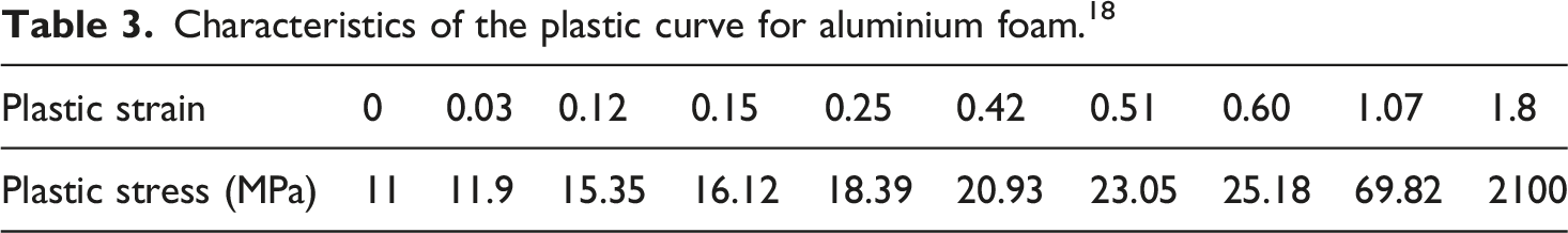
In the case of GSP, the gel properties reported in literature 19 are utilised for modelling purposes, and the gel is assumed to behave like an isotropic elastic material with a density of 1000 kg/m3, Poisson’s ratio (υ) of 0.4999,and Young’s modulus (E)of 6.9 MPa. The plastic stress strain (deformation) properties are also obtained from literature. 19
Numerical validation
The explicit dynamic simulation of a square-cored sandwich panel is performed under air-blast explosions. Figure 3(a) illustrates the comparison between the computational findings and the tested data determined by Dharmasena et al.
5
for the FPD at 1, 2, and 3 kg TNT. Figure 3(b) compares the structures that have been deformed numerically and experimentally. The graph in Figure 3(a) illustrates that a good agreement is noted for the simulated and tested data sets of FPDs. Similarly, a close resemblance is observed between the simulated deformation models and experimental deformation models obtained by Dharmasena et al.,
5
shown in Figure 3(b). Comparison of the simulated and experimental
5
(a) FPD graphs and (b) deformation models.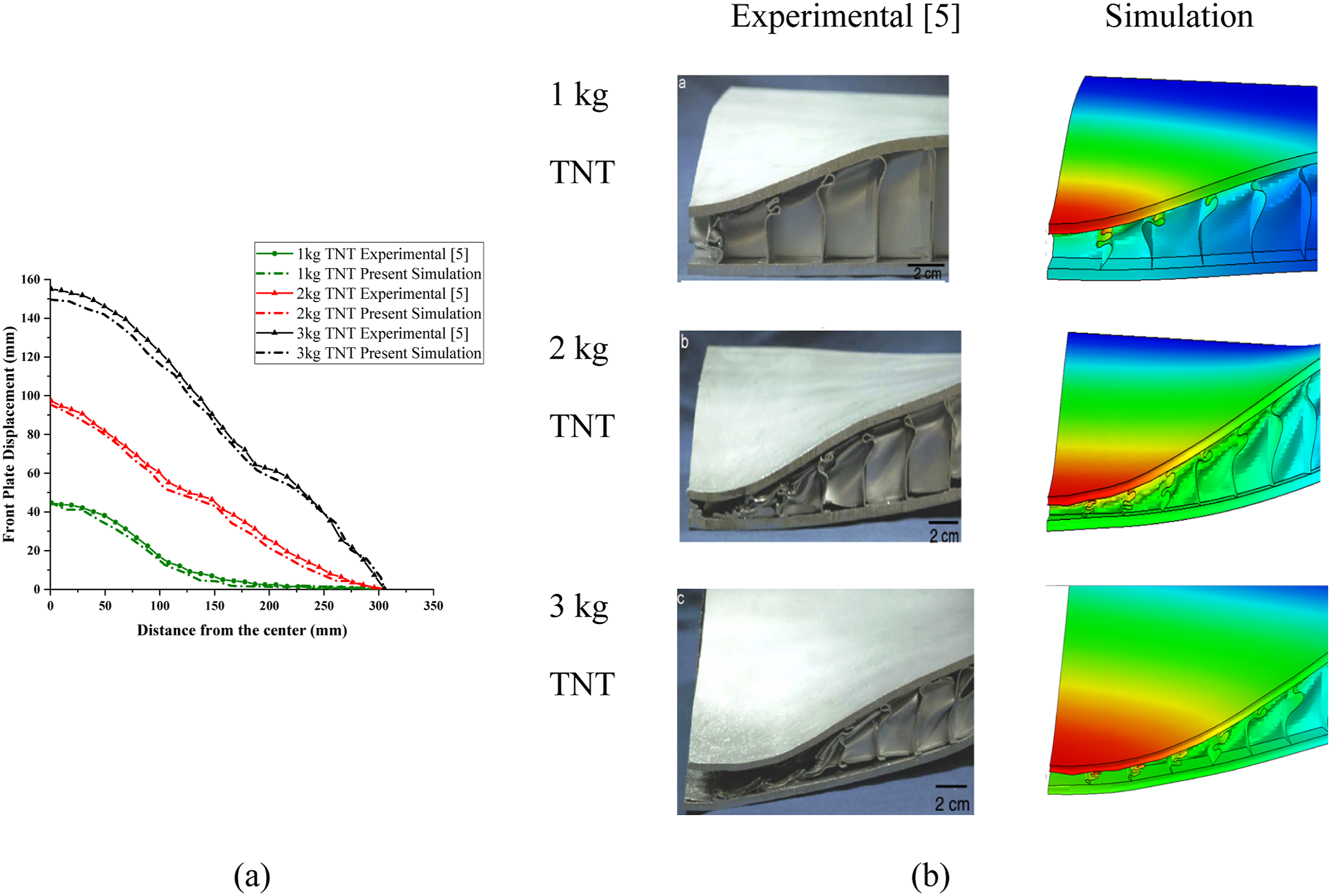
Meshing properties
The solid, 3-Dimensional, continuum, 8-noded reduced integration (C3D8R) elements are used to discretize both the upper and lower plates for each model. The finite element mesh of the core consisted of four-noded, reduced integration shell elements (S4R). In order to prevent element distortion in numerical simulations, enhanced hourglass control is included. A mesh convergence study is performed for the square core sandwich panel (validation model) at a blast load of 2 kg TNT. The maximum FPD of the panel at the center point is noted for global element mesh sizes of 25 mm, 20 mm, 15 mm, 10 mm, 5 mm, and 4 mm. It can be observed from Figure 4 that the graph of peak displacement versus time for mesh sizes of 5 and 4 mm almost coincides. This indicates that the deflection value will not change with further reduction in the element size, and mesh convergence is achieved. Thus, a global mesh size of 5 mm for validation model can be deemed appropriate. Mesh convergence study for square-cored sandwich (validation) model at 2 kg TNT.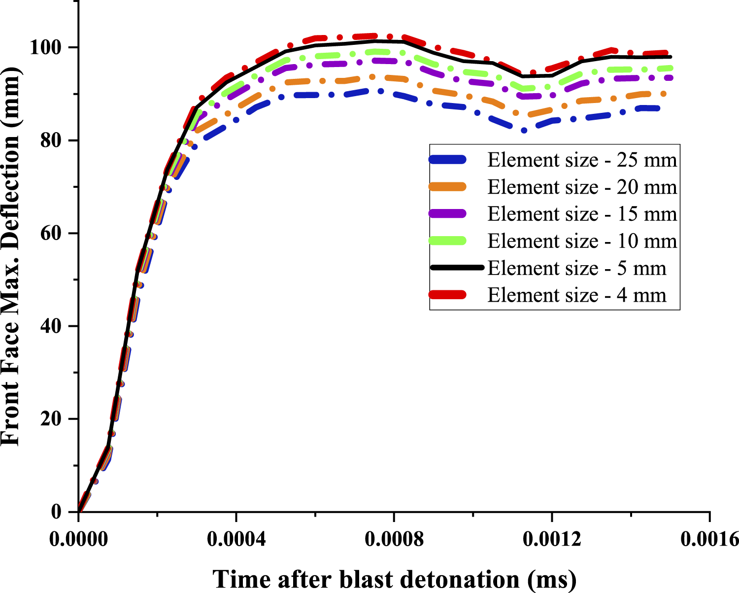
Results and discussion
Effect of core thickness
The GSP model is analyzed to assess the blast resistance of the panel, when the core thickness is varied at an explosive mass of 2 kg of TNT. The core thickness of 0.76 mm (used in the original validation model), 1.5 mm, and 2 mm is compared with respect to FPDs and BPDs. The three models are labeled as GSP-t-0.76, GSP-t-1.5, and GSP-t-2 having core thicknesses of 0.76 mm, 1.5 mm, and 2 mm, respectively. Since the thickness of the cores is very less, there is negligible change in the mass of the three panels.
Figure 5 shows that the increment in core thickness substantially reduces the FPDs and BPDs of the panels. The FPD of the GSP-t-1.5 and GSP-t-2 models reduces by 13% and 34%, respectively, compared to the GSP-t-0.76 model. Similarly, a reduction of 11% and 32% is observed in the BPD of the GSP-t-1.5 and GSP-t-2 models compared to the GSP-t-0.76 models. Therefore, comparing the GSP-t-2 and GSP-t-0.76 models, it can be concluded that an approximate reduction of 33% is obtained in the panel deformation by increasing the core thickness by only 1.24 mm. As previously mentioned, there is a negligible increase in the panel’s mass. Thus, the thickness of the core is an important model parameter to be considered while designing effective sandwich panels for blast protection applications. The deformation models of the three sandwich configurations are illustrated in Figure 6. Deformation comparison for GSP at various core thicknesses at 2 kg TNT load. Deformation (in m) models for GSP at various core thicknesses at 2 kg TNT load.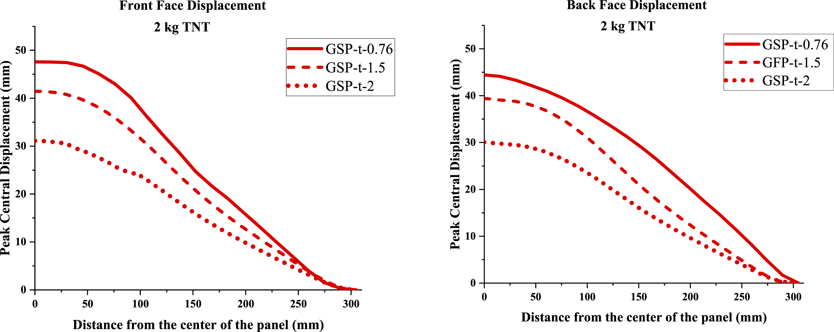
Effect of SoD
The SoD is a significant parameter for the explosive analysis of the sandwich structure and for assessing its blast response. The effect of SoD is also evaluated for the GSP at SoDs of 100 mm, 150 mm, and 200 mm, labelled as GSP-SoD-100, GSP-SoD-150, and GSP-SoD-200, respectively. The FPD and BPD graphs for the same at an air-blast explosion of 2 kg TNT are illustrated in Figure 7. It can be observed that there is a moderate reduction in the panel deformation when the SoD is increased from 100 mm to 150 mm. However, the panel deformation is exponentially reduced at the SoD of 200 mm. As expected, the panel’s deformation decreases with increasing stand-off distance of the explosive. This happens because lower impact forces act on the panel as the SoD increases, which is the result of the blast wave losing energy because of pressure attenuation. Air also dissipates energy before it reaches the panel by acting as a buffer medium. As a result, the panel’s overall displacement is decreased, due to which less severe structural deformation and lesser impulse transfer. Deformation comparison for GFP at various SoDs for 2 kg TNT load.
The FPD of the GSP-SoD-150 and GSP-SoD-200 models reduces by 13% and 74% respectively, compared to the GSP-SoD-100 model. Likewise, a reduction of 15% and 75% is observed in the BPD of the GSP-SoD-150 and the GSP-SoD-200 models compared to the GSP-SoD-100 panel. The deformation models of GSPs at different SoDs can be observed in Figure 8. Negligible core compression is observed for all the GSP models. Subtle front face-sheet bending is observed for the GSP-SoD-100 and the GSP-SoD-150 models but not for the GSP-SoD-200 panel. This is because as the distance increases, the intensity of the blast wave reduces and impulse reaching the panel is very low. Maximum deformation is observed at the center and the edges of the structure remain un-deformed. Deformation (in m) models for GSP at various SoDs for 2 kg TNT load.
It should be noted that the parametric effects of core thickness and stand-off distance are investigated only for the gel-filled configuration and are not generalized to other core types. Although similar qualitative trends such as the reduction in front and back plate deflection with increase in core thickness and stand-off distance may be expected for other core configurations as well (HSP and FSP), the underlying deformation mechanisms and the overall panel response will differ based on the core filler material.
Strain rate analysis of HSP
Numerous factors, including the imposed loading condition, operating temperature, and underlying microstructural characteristics, etc can influence strain-rate-dependant response of a material. It is well established that, at elevated strain rates, the mechanical response of metallic materials is enhanced, leading to increased flow stress, yield strength, and resistance to deformation.13,14 In this context, the effect of HSR conditions on blast response of sandwich panels in comparison with LSR conditions is investigated in the present section in order to evaluate the significance of strain-rate-effects in dynamic loading problems.
The HSP model, having two different strain rates for the AL-6XN (steel) material, of 0.1/s and 3500/s, respectively, (as illustrated in Figure 2(c)) is simulated using FE solver, for explosives of 1 kg, 2 kg, and 3 kg of TNT, to investigate the influence of strain rate on deformation behaviour. The system is considered to operate at a temperature of 296K throughout the analysis. The plastic deformation properties of AL-6XN at 0.1/s and 3500/s, (reported in literature
20
) are incorporated to assess strain-rate sensitivity. The results obtained for the FPD and BPD for all three explosives of 1, 2, and 3 kg TNT are plotted in Figure 9. The hollow core sandwich panel having an applied strain rate equal to 0.1/s (with respect to AL-6XN material) is labeled as HSP-LSR, wherein ‘LSR’ stands for ‘low strain rate’. Similarly, the model having a strain rate of 3500/s for hollow core panel is labeled HSP-HSR, where ‘HSR’ denotes ‘high strain rate’. Rising the strain rate from 0.1/s to 3500/s leads to markedly lower deflections in the FPD and BPD, as evident from the Figure 9. At a blast load corresponding to 1 kg TNT, an elevated strain rate of 3500/s, yields a 46% lower FPD, and a 51% lower BPD compared to the 0.1/s condition. Similarly, when the HSP is subjected to 2 kg TNT load, elevating the strain rate from 0.1/s to 3500/s produces a decrement of 28% and 29%, respectively, in the FPD and BPD of the panel. Under a 3 kg TNT charge, the HSP exhibits a 20% and 22% decrease in FPD and BPD, with the enhancement in strain rate. Deformation comparison of HSPs at various strain rates.
The observed reduction in the BPD of the panel with increasing strain rate may be attributed to the strain rate sensitivity response of the material. AL-6XN, being a ductile material, undergoes significant plastic deformation prior to failure. Under LSR conditions, the material exhibits larger plastic strains resulting in greater overall deformation. Analogously, under HSR loading, the material demonstrates increased resistance to deformation, leading to reduced deflection. This behaviour is consistent with rate-dependent strengthening typically observed in metallic materials, wherein the effective flow stress increases with strain rate. Although the present macro-scale FE model does not explicitly capture microstructural mechanisms observed under HSR conditions, such as nucleation of dislocations or twinning, the observed trends are in agreement with rate-dependent material response reported in literature.21,22
The deformation behavior for the sandwich panels is shown in Figure 10. It can be seen that for 1 kg TNT, no central core compression is observed for the HSP-HSR model, whereas the HSP-LSR panel shows moderate core crushing at the center along with limited bending of the front face sheet. Slight compression at the central blast impact zone is observed for the HSR models at 2 and 3 kg TNT. In contrast, the LSR model at 2 and 3 kg TNT exhibits significant central core compression and bending of the panel. In agreement with previous results, the primary modes of failure for the sandwich panels in this section are core crushing due to compressive load and face-sheet stretching under tension, along with panel bending (for higher loads). Deformation (in m) models of HSPs at various strain rates.
The internal energy for these models is plotted in Figure 11. It can be observed that the magnitude of internal energy is significantly lower for the HSR models (having less deformation) compared to the LSR panels (having more deformation) at all loads. This behaviour can be attributed to the fact that the internal energy in blast simulations represents the energy absorbed through plastic deformation mechanisms. Therefore, even though, the panel exhibits increased strength and stiffness at higher strain rates, the associated reduction in deformation limits the extent of plastic yielding and progressive collapse within the structure.
23
Consequently, this results in a smaller volume of the panel undergoing irreversible plastic deformation, and therefore, lower plastic work, leading to the reduction in the internal energy absorption. Internal energy for HSP at various strain rates.
Strain rate analysis of FSP
Dynamic explicit analysis of the FSP is also conducted under both LSR and HSR conditions. In the present study, the strain-rate dependent behaviour of aluminum foam is investigated within a continuum-scale FE framework and the observed panel response is interpreted. Figure 12 shows the deformation graphs of FSP under two separate strain rate conditions (0.004/s and 12,000/s) for aluminium foam. In this section also, the models under strain rate conditions of 0.004/s and 12,000/s for aluminium foam are labeled as FSP-LSR and FSP-HSR, respectively.The plastic deformation properties of closed cell aluminium foam at 0.004/s and 12,000/s, (reported in literature
20
) are incorporated to assess strain-rate sensitivity. Deformation comparison for the FSP at various strain rates.
Under 1 kg TNT explosive load, increasing the strain rate from 0.004/s to 12,000/s results in reduction of 53% and 41%, for the FPD and BPD, respectively. Likewise, for an explosive of 2 kg TNT charge, a decrement of 52% and 48% is observed in the FPD and BPD, respectively, for the FSP-HSR model compared to the FSP-LSR model. Similarly, the FPD and BPD reduced by 50% and 47%, respectively, at a blast intensity of 3 kg TNT under elevated strain rate conditions. The results indicate that, the FSP subjected to higher strain rate conditions (12,000/s) exhibits lower deflection compared to the lower strain rate FSP (0.004/s), which is again consistent with the findings obtained in the previous section.
The deformation models for these panels are shown in Figure 13. It can be seen that localized core crushing at the center occurs predominantly under 3 kg TNT load for the FSP-HSR model. Although a certain degree of localized core compression is also evident at 2 kg TNT load for the same model, it remains negligible due to the minimal depth of central deformation. But, conversely, for the low-strain-rate model, substantial central deformation is observed at 1 kg and more prominently at 2 kg TNT loading. This includes noticeable tensile stretching of the front face sheet along, localized core crushing along with global panel bending. Additionally, for the LSR panels, it can be seen that the deformation is more uniform and spreads to a larger area away from the center of the panel. For the HSR models, the deformation is localized at the center. This is because, at a higher strain rate, there is less time for movement of dislocations, leading to non-uniform, localized plastic deformation. Deformation (in m) models for FSP at various strain rates.
The internal energy for these panels is shown in Figure 14. It is observed that, the total absorbed energy increases with extent of plastic deformation, since higher deformation corresponds to more plastic work being done. Since higher strain rates lead to reduced deformation, panels experiencing deformation at a LSR of 0.1/s absorb more energy compared to the panels that underwent defamation at a HSR of 3500/s. Internal Energy for FSP at various strain rates.
Mass efficiency
Mass performance metric (Pm) for the HSP and FSP models at 2 kg TNT.
As seen from Table 4, the HSP model exhibits relatively higher Pm values under both LSR and HSR conditions, indicating lower mass efficiency. Analogously, the FSP model, despite having higher mass, shows lower values of Pm under both loading conditions, reflecting superior deformation resistance relative to its weight. Furthermore, a notable reduction in the Pm values is observed for all the panels under HSR conditions compared to LSR loading, showing the influence of strain-rate-dependent strengthening in metallic materials. Overall, amongst all configurations, the FSP-HSR model exhibits the lowest value of Pm, indicating the most efficient blast resistance performance.
Conclusions
The main conclusions inferred from the present study are: • Parametric studies were carried out on the GSP at 2 kg TNT by varying the core thickness and the SoD. A reduction of 11% and 32% is observed in the BPD of the panel with core thicknesses of 1.5 mm and 2 mm, compared to the model having a 0.76 mm core thickness. • A reduction of 15% and 75% is observed in the BPD of the GSP-SoD-150 and the GSP-SoD-200 models compared to the GSP-SoD-100 panel. • The deformation behavior of HPs and FSPs was analyzed under two different strain rates. Following an increase in strain rate from 0.1/s to 3500/s for the HSP, a 28% and 29% decrease in the FPD and BPD, respectively, was observed for a blast load of 2 kg TNT. • Similarly, for the FSP, for a 2 kg TNT explosive load, increasing the strain rate from 0.004/s to 12,000/s resulted in a reduction of 52% and 48%, respectively, for the FPD and BPD. • Amongst all the panels analysed under strain rate effect, the FSP model, despite having higher mass, shows lower values of Pm (mass-performance metric) under both LSR and HSR loading conditions, reflecting superior deformation resistance relative to its weight.
Footnotes
Funding
The authors received no financial support for the research, authorship, and/or publication of this article.
Declaration of conflicting interests
The authors declared no potential conflicts of interest with respect to the research, authorship, and/or publication of this article.