
Abstract
In this paper, a novel arch-shaped BFRP tube with longitudinal BFRP bars pre-bonded on the inner wall is proposed and fabricated. It can provide strength in both circumferential and longitudinal directions and is suitable for the rapid construction of arch bridges in island environments by filling with seawater sea-sand coral aggregate concrete (SWCC) in situ. Ten SWCC-filled BFRP tubular arches were fabricated and tested under monotonic loading. Test variables include the wall thickness of the BFRP tube, the radius angles of the arch, and with or without pre-bonded BFRP bars. Test results showed that the failure modes of arches without BFRP bars were bending failure under the loading point. The ultimate bearing capacities were increased by 33.1% and 71.7% as the wall thickness increased from 2 mm to 3 mm and 4 mm, respectively. The failure modes of arches containing pre-bonded BFRP bars were bending-shear failure close to the loading plate. The ultimate bearing capacity of arches, which containing BFRP bars, with a wall thickness of 2 mm, 3 mm, and 4 mm increased by 215%, 248%, and 189%, respectively, compared with the specimens without BFRP bars. The integrity and ultimate bearing capacities of arches decreased with the increase of the radius angle and their failure modes exhibited obvious brittle damage characteristics. The proposed new type of arch has good prospects for application in the marine environment.
Keywords
Introduction
There are many challenges to efficiently carry out infrastructure construction in harsh island environments. First, the service environment is extremely corrosive and the construction window is short; second, there is a lack of human resources, large-scale equipment, and construction materials, in particular, raw materials for concrete need to be transported from far away inland, which is costly and time-consuming. The use of locally available seawater, sea-sand, or even coral aggregates for concrete preparation (i.e., seawater sea-sand coral aggregate concrete, SWCC) can significantly reduce the construction cost and shorten the construction period. The study of SWCC has again received wide attention from scholars in recent years (Xiao et al., 2017; Dong et al., 2020b; Zhou et al., 2021). However, the application of SWCC faces a serious bottleneck problem, that is, the excessive chloride ion content, which will lead to accelerated corrosion of steel and thus seriously shortens the service life of infrastructure. Moreover, due to the brittle and porous nature of coral aggregates, the strength and long-term performance of the coral aggregate concrete in the marine environment is also relatively low (Li et al., 2013), making it difficult to be used reliably as a structural member (Wang et al., 2021; Cheng et al., 2018; Niu et al., 2020; Lyu et al., 2019; Da et al., 2016; Su et al., 2018).
Fiber-reinforced polymers (FRPs) have good resistance to chloride ions attack and superior durability (Cromwell et al., 2011; El-Hacha et al., 2010; Teng et al., 2018). It is regarded as a promising material for replacing ordinary steel reinforcements. By combining FRP bars/tubes with the seawater sea-sand concrete, which is rich in chloride ions, good comprehensive performance can be achieved (Dong et al., 2020a, 2021; Gao et al., 2020; Xiong et al., 2021; Zhang et al., 2020). To date, numerous ways have been proposed in the last three decades to promote the application of FRP in civil engineering, mainly include using it as internal reinforcements (De Luca et al., 2010; Tobbi et al., 2014; Afifi et al., 2014; Hadi et al., 2016; Pantelides et al., 2013) and using it as external strengthening/confinements (Zeng et al., 2020; Wang et al., 2020; Hadi et al., 2015; Yu et al., 2017; Ozbakkaloglu et al., 2013). Among them, concrete-filled FRP tube (CFFT) structures are an efficient structural element, since the FRP tube can not only be used as permanent formwork to facilitate the construction but also can improve the mechanical properties of the core concrete by offering lateral confinement (Wei et al., 2021; Bazli et al., 2020; Wang et al., 2017). What is more, the FRP tube can also protect the core concrete from a harsh service environment. Therefore, the combination of the SWCC and the FRP tube has good prospects for application in harsh marine environments.
At present, the research of CFFT structures adopts linear members, while the research and application for curved CFFT structures are relatively raw and are still in the initial stage (Meng and Wang, 2018). Dagher et al. (2012) investigated the bending performance of six CFFT arches by three-point bending test. The test results found that the tensile rupture of the FRP tube occurred first at the bottom side of the top of the arch, and the arch changed to be a three-hinged arch. As the load continues to be applied, the tensile rupture of FRP also occurred at about 1/4 span and the arch lost its bearing capacity. The study proved that the CFFT arch has good strength, stability, and fatigue resistance. Nonlinear finite element (FE) analyses on CFFT arches under static and dynamic loads were carried out by Wen et al. (2012) and Walton et al. (2016), respectively. Based on the developed technology for the preparation of curved FRP tubes (Tomblin, 2006), and also supported by the aforementioned laboratory test data and FE analysis data, Dr. Dagher, together with relevant experts and investors, established the company named Advanced Infrastructure Technologies (AIT) Bridges, specializing in the consulting, design, and construction services for the above-mentioned CFFT arch bridges. CFFT arches can not only be applied to the above-mentioned culvert arch bridges but also the underground protection project. Wang and Chen (2018) conducted a series of studies on the blast resistance performance of arch-shaped CFFT underground protection engineering. The test results found that after suffering two explosions, the CFFT arches could remain intact and show good blast resistance performance, demonstrating the possibility of its application in underground protection engineering. Wang et al. (2019) investigated the dynamic response of CFFT arches under blast loading with two types of Carbon-FRP (CFRP) wall thicknesses and two types of concrete. The test results showed that the blast resistance performance of CFFT arches could be improved by increasing the CFRP wall thickness and concrete strength. In addition, De Waal et al. (2018) designed a novel double-skin tubular arch bridge system, which consists of an outer FRP tube, an inner steel tube, and a layer of concrete sandwiched between them.
Unlike isotropic steel tubes, FRP tubes prepared at this stage are linear and anisotropic and can mainly provide circumferential tension strength (FRP tubes prepared by the pultrusion process mainly provide longitudinal strength). However, in the actual arch structure, there are not only axial forces but also certain bending moments. Therefore, not only circumferential confinement but also longitudinal reinforcements are required. According to the need for rapid construction of high durability arch bridges in an island environment, a new type of integrated basalt-FRP (BFRP) tube arch with longitudinal BFRP bars pre-bonded in the inner wall and with the SWCC filled inside was fabricated and tested. The effects of parameters such as the wall thickness of the BFRP tube, radius angles, and with or without longitudinal BFRP bars were analyzed through the bearing capacity test under monotonic loading. The research results showed that the proposed new arch bridge has good bearing performance, and the pre-bonded BFRP bars in the inner wall can significantly improve the bearing performance of the arch, which shows a broad application prospect in the infrastructure construction in distant islands.
Materials
Basalt fiber sheets and resin
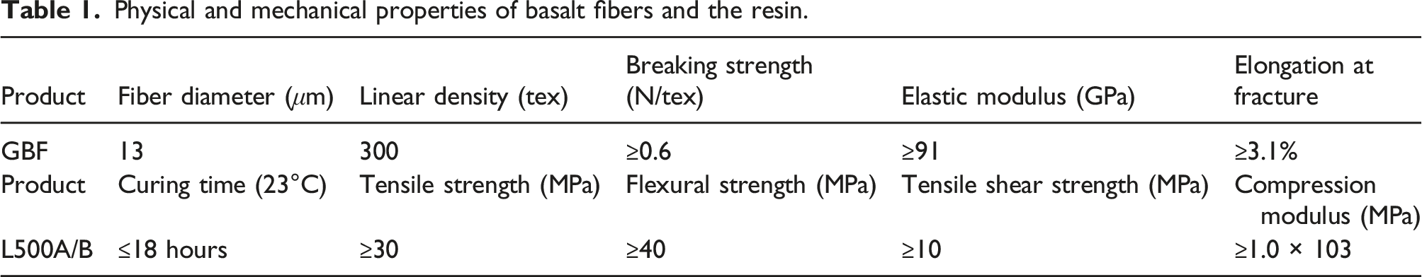
The BFRP tube used in this paper was prepared by the wet lay-up process in the laboratory. As shown in Figure 1(a), the basalt fiber sheets used for winding and preparing the BFRP tube were provided by Zhejiang GBF Basalt Co., LTD. As shown in Figure 1(b), the resin matrix used was provided by Shanghai Sanyu Resin Co., LTD. with a product model of L-500AS/BS. The mass ratio of the BFRP fiber sheet and the resin was 7:3. The properties provided by the manufacturer are listed in Table 1. Raw materials for preparing the BFRP: (a) basalt fiber sheets and (b) resin matrix. Physical and mechanical properties of basalt fibers and the resin.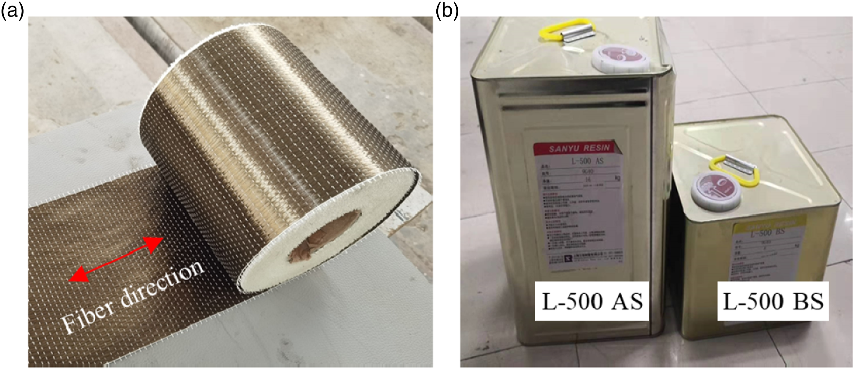
BFRP bars and tubes
The BFRP bars bonded to the inner wall of the BFRP tubular arch are produced and supplied by Jiangsu Green Materials Valley New Material T&D Co., Ltd. (GMV), and its nominal diameter is 8.0 mm. According to the ASTM D7205-11 (2011), the ultimate tensile strength was measured to be 1177 MPa, the modulus of elasticity was 46.9 GPa, and the ultimate tensile strain was 0.025.
Following the ASTM D2290-12 (2012), the “disk-split” method was used to test the hoop tensile properties of BFRP tubes. The measured tensile strength of the BFRP tube was about 278.4 MP to 283.9 MPa, and the corresponding elastic modulus was 12.7 GPa to 12.8 GPa.
Seawater sea-sand coral aggregate concrete
The artificial seawater was prepared according to the Testing and Materials (2013), and the chemical composition mass ratio is CaCl2: KBr: MgCl2: KCl: Na2SO4: NaHCO3: NaCl = 1: 0.089: 4.483: 0.599: 3.526: 0.173: 21.147. As shown in Figure 2(a), the adopted natural sea-sand with a fineness modulus of about 2.4 was mined in the coastal city named Zhangzhou in Fujian Province, China. It belongs to the medium sand class. As shown in Figure 2(b), the natural coral aggregates mined in the South China Sea with a particle size of 0.5 cm–2 cm were used. The tested particle gradation curves of the sea-sands and the coral aggregates are shown in Figure 2(c). In addition, ordinary silicate cement with a grade of 42.5 in the Chinese standard was used. Raw materials for the production of the SWCC: (a) sea-sands; (b) coral aggregates; and (c) particle gradation curves.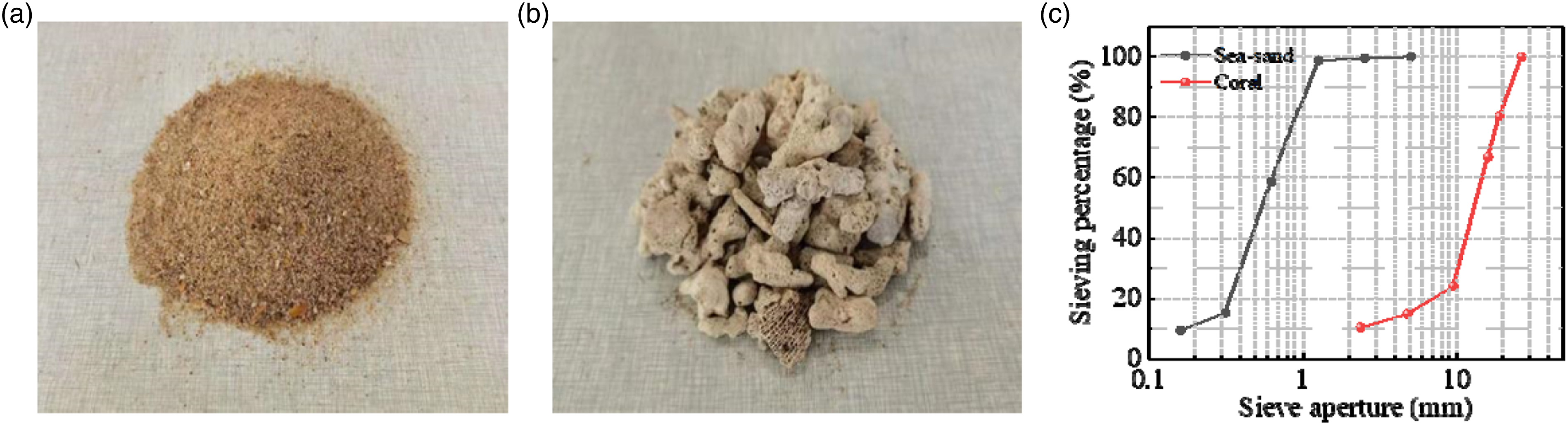
The detailed mass mix ratio of the SWCC is Portland cement: artificial seawater: sea-sands: coral aggregates: water reducer = 1.00: 0.55: 1.50: 2.50: 0.012. The water reducer used is a polycarboxylate superplasticizer, which has a water reduction of 26%. The SWCC was prepared by mechanical mixing in the laboratory. Cylindrical specimens with 150 mm in diameter and 300 mm in height were made and the cylindrical compressive strength at 28 days was measured to be 18.58 MPa.
Experimental program
Production of curved BFRP tubes
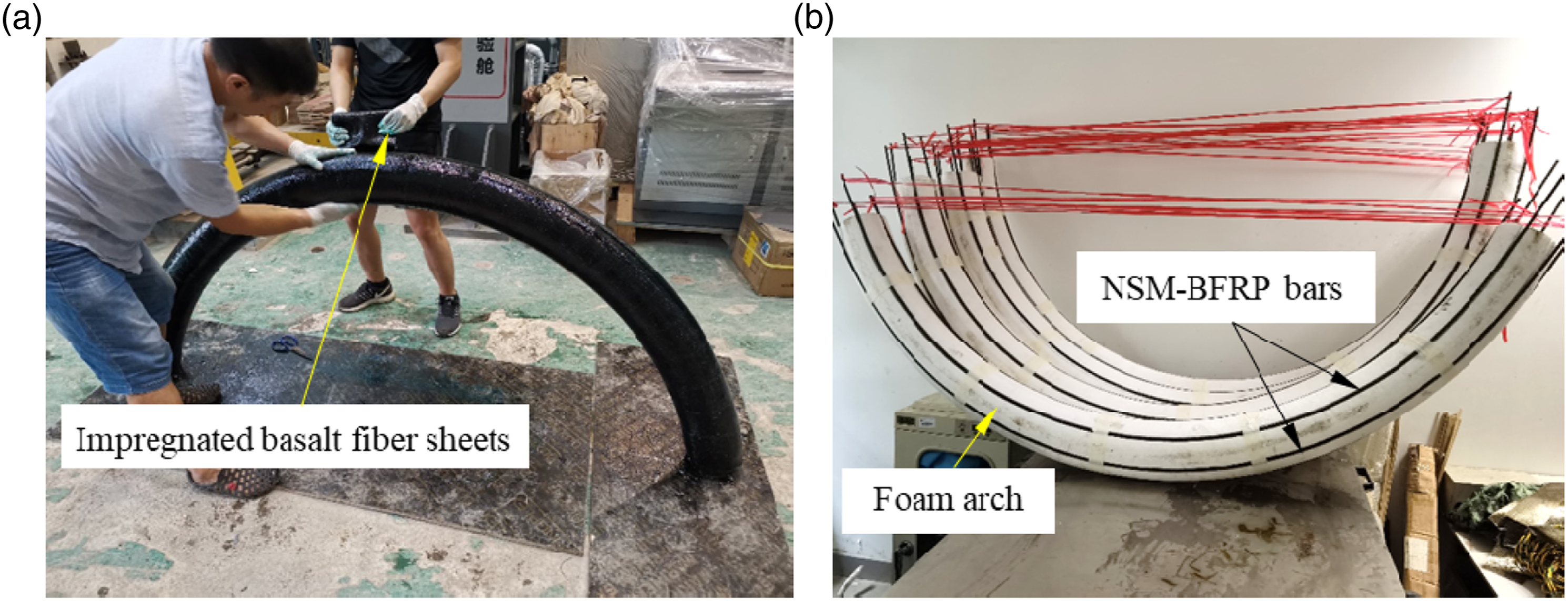
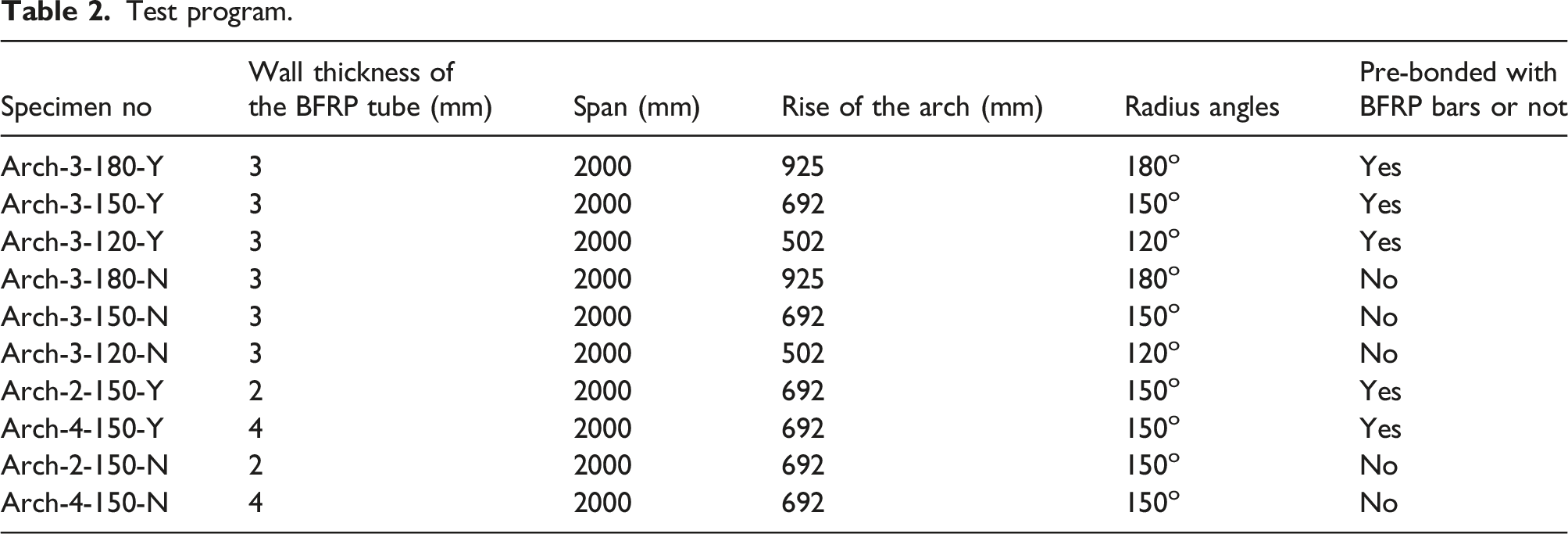
As shown in Figure 3(a), the curved BFRP tube was made by manually winding basalt fiber sheets on the surface of a customized curved foam arch. The diameter of the foam arch was 150 mm, and the resin-impregnated basalt fiber sheets were wrapped at an approximate angle of 67.5° to the axis of the foam arch. The inner foam was removed after the resin was cured. Considering that the construction of a curved BFRP reinforcement cage in situ is time-consuming and is not easy to remain curvilinear shape due to the linear elastic characteristic of FRP bars, grooves were cut on the surface of the curved foam arch in advance, and the BFRP bars were near-surface-mounted (NSM) into the grooves and were temporary fixed as shown in Figure 3(b). It should be noted that the curved BFRP bars are bent from straight bars, which causes a certain amount of prestressing in the bars themselves. According to equation (1) (Zhu et al., 2017), the corresponding prestress of BFRP bars with different rise of specimens (Table 2) were 198.4 MPa, 159.7 MPa and 114.5 MPa, respectively. The prestress accounted for 16.8%, 13.5% and 9.7% of the ultimate strength (1177 MPa), respectively. Preparation technology of BFRP tubular arches: (a) wrapping the BFRP sheets and (b) foam arches with near-surface-mounted BFRP bars. Test program.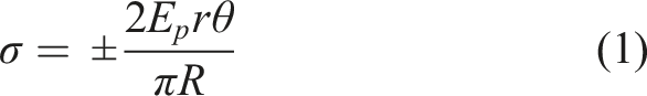
After that, the impregnated basalt fiber sheets were wrapped following the aforementioned same process on the outer side of the foam. After the resin was cured and the foam was removed, the new integrated BFRP tube arch with longitudinal BFRP bars well pre-bonded was obtained.
Casting of the SWCC-filled BFRP tubular arches
As shown in Figure 4(a), the prepared curved BFRP tubes were erected upside down on wooden supports. Then, as shown in Figure 4(b), the prepared fresh SWCC was directly cast into the inverted BFRP tube from both ends and was compacted with a vibration rod from the two ends. After 28 days of curing in the laboratory, as shown in Figure 4(c), the CFFT arch was turned over and the foot foundations were cast with C50 concrete. Casting of the SWCC-filled BFRP tubular arches: (a) prepared curved BFRP tubes; (b) casting the SWCC; and (c) casting the foot foundations.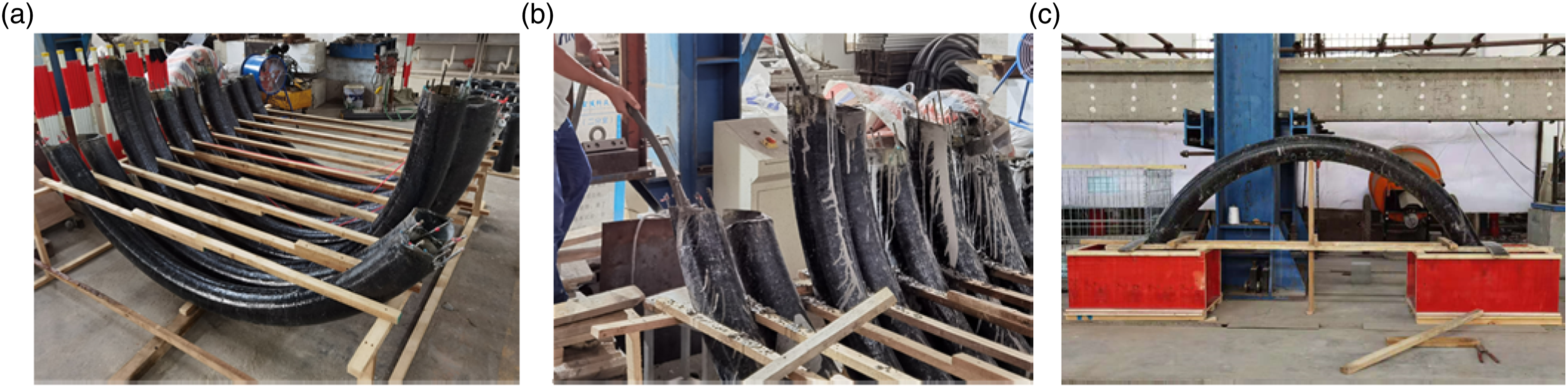
Test program and instrumentations
The number of the prepared ten SWCC-filled BFRP tubular arches is shown in Table 2. Each specimen is named in the following format: Arch-x-y-N(/Y), where “Arch” denotes the arch specimen; the number “x” denotes the nominal wall thickness of the BFRP tube (in mm); the number “y” denotes specimens with pre-bonded BFRP bars.
The loading device and the layout of the instrumentations are shown in Figure 5(a). The test was conducted on a servo actuator for monotonic loading. A load sensor was connected to the loading head of the actuator to accurately and synchronously record the loads. The test was initially loaded at a rate of 1 kN/s, and when the load reached 10 kN, it was changed to displacement control mode with a loading rate of 0.5 mm/min. Three linear variable differential transformers (LVDTs) were used to measure the displacement of the arches at different locations during the loading process (i.e., the middle span and the quarter spans). Sixteen strain gauges were attached to each specimen to measure the axial and circumferential strain at the top, side, and bottom of the arch. Since the top surface at the middle span is in contact with the loading steel block, the strain gauges are arranged only on the side and bottom of the arch. All measurements, including load, displacement, and strain, were recorded with a TDS530 data acquisition system. In addition, as shown in Figures 5(b) and (a) non-contact full-field digital image correlation (DIC) technique was used to monitor the strain field during the test. The DIC method is used to obtain the displacement field on the specimen surface by tracking the pixel motion of the scattered spots on the specimen surface during the test (Wang et al., 2015). The displacement field is then post-processed to obtain the strain field. Test setup and instrumentations of arch specimens: (a) schematic diagram and (b) photograph.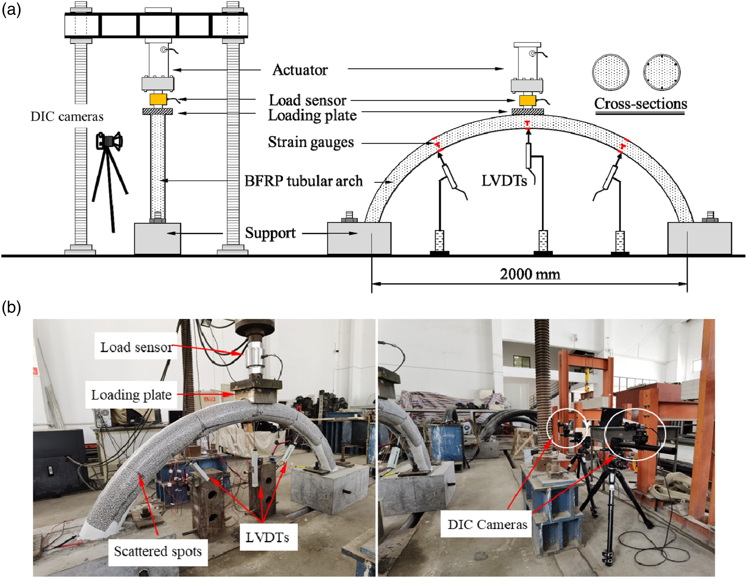
Test results
Failure modes
In this paper, the effects of three parameters, that is, the wall thickness of the BFRP tube, the radius angles of the arch, and the containing of BFRP bars or not, were investigated. The failure modes under different variables are shown in the following Figure 6. Failure modes of specimens: (a) Arch-2-150-N; (b) Arch-3-150-N; (c) Arch-4-150-N; (d) Arch-2-150-Y; (e) Arch-3-150-Y; (f) Arch-4-150-Y; (g) Arch-3-180-N; and (h) Arch-3-180-Y.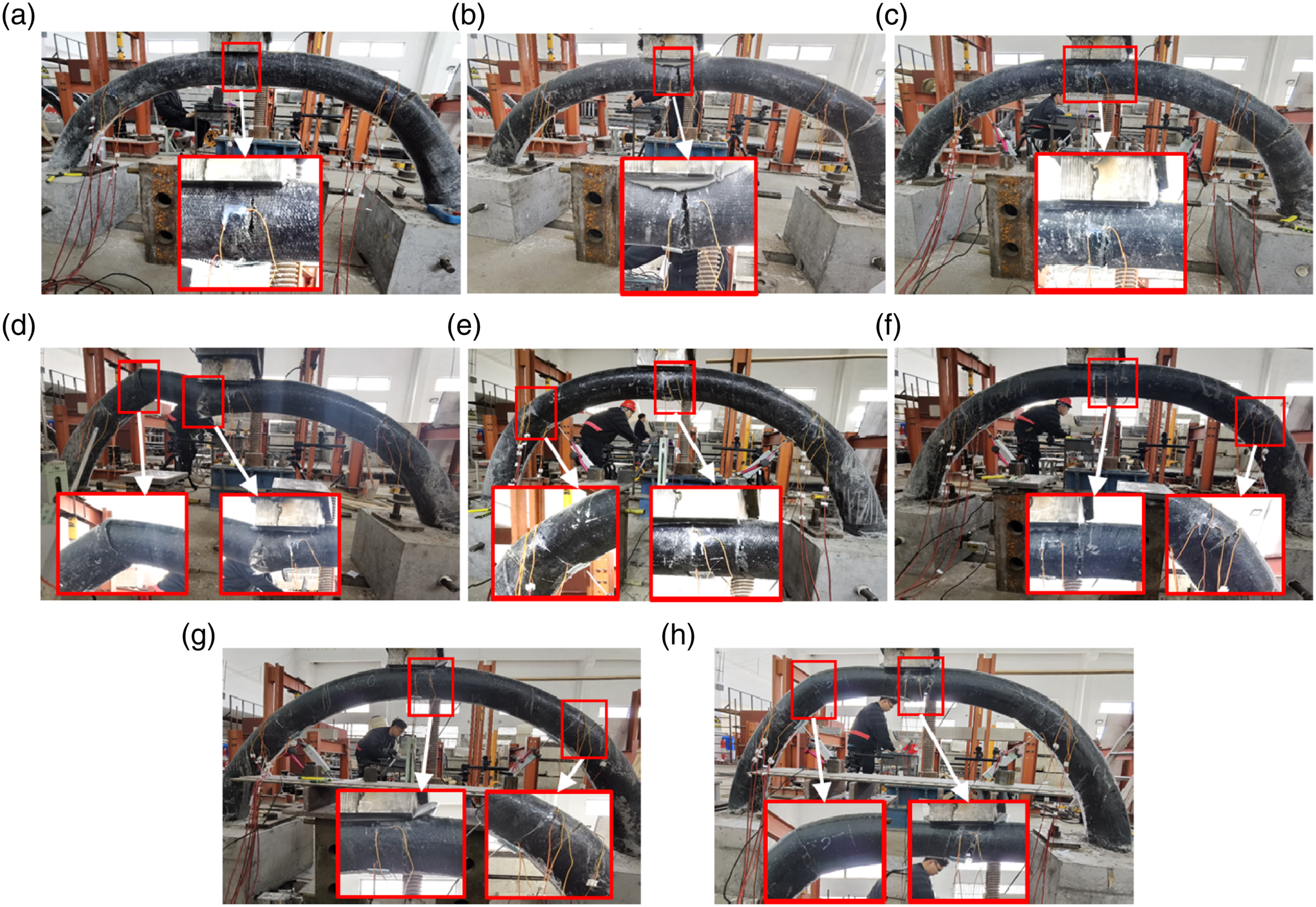
Figure 6(a)–(c) shows the failure modes of the arches without BFRP bars under different wall thicknesses at the same radius angle (150°). In the process of loading, cracks first appeared at the bottom of the loading point, and then new cracks appeared at the outside of the left and right quarter section in turn. As the loading continues, the cracks at these points became wider and wider. The bearing capacity of the specimen was rapidly reduced and the specimen was damaged when the crack width exceeds a certain limit. Figure 6(d)–(f) shows the failure modes of the arches containing BFRP bars under different wall thicknesses at the same radius angle (150°). Compared to the failure modes of the Arch-2(3/4)-150-N specimens as shown in Figure 6(a)–(c), the location of the first crack in the Arch-2(/3/4)-150-Y specimens shifted from the bottom of the mid-span to the edge of the loading steel block. This is because the Arch-2(3/4)-150-N specimen has the largest bending moment in the middle span, so that is where the cracks first appeared. While, for the Arch-2(/3/4)-150-Y specimens containing BFRP bars, the bending moment can be well withstood by the BFRP bars so that the tube at the mid-span was not prematurely damaged. According to the location of the initial cracks observed in the Arch-2(/3/4)-150-Y specimens, it was believed that the shear force generated at the edge of the steel loading plate was the main reason for the damage.
Figure 6(g)–(h) shows the failure modes of specimens with the radius angle of 180°, the failure mode of Arch-3-180-N was similar to Arch-2(3/4)-150-Y specimens. Although there were no longitudinal BFRP bars pre-bonded, the larger radius angle led to a relatively lower tensile stress at the tube bottom of the mid-span section, causing the failure to be still controlled by the shear force generated at the edge of the loading steel plate. As to the Arch-3-180-Y specimen, it exhibited a similar failure mode to Arch-2(3/4)-150-Y specimens due to the existence of the internal longitudinal BFRP bars.
The strain contours of the Arch-3-120-N and Arch-3-120-Y specimens obtained by the DIC method at different loading stages are shown in Figure 7 and Figure 8. For the Arch-3-120-N specimen, when loaded to 71.8 kN (Figure 7a), obvious tensile strains appeared at the bottom part of the arch under the loading plate. As the load increased to 97.9 kN, new obvious concentrated tensile strains appeared at the top part of the arch near the quarter span (Figure 7b). When the load was further increased to 108.5 kN, which was the ultimate load (Figure 7c), the tensile strains (which represents obvious cracks) at the above two locations developed further. Then, as the loading continued, the bearing capacity of the arch gradually decreased. When the load dropped to 102.7 kN (Figure 7d), some of the scattered spots began to be unrecognizable. Finally, the arch was destroyed with a sudden fracture at the mid-span and the quarter spans. Strain contours of the Arch-3-120-N specimen.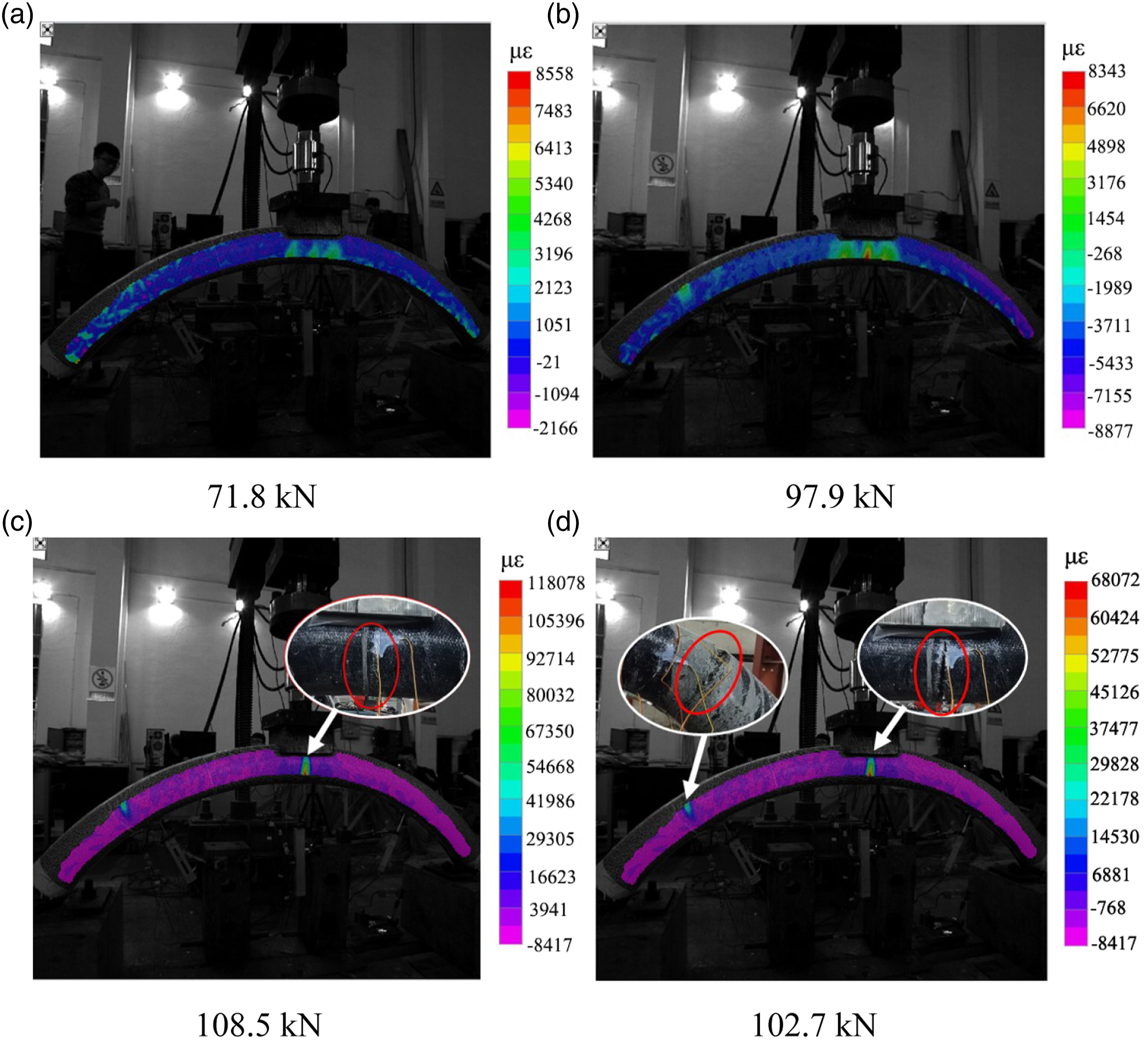
For the Arch-3-120-Y specimen, as shown in Figure 8a, when loaded to 104.7 kN, there was a significant strain concentration at the edge of the loading steel plate, which was caused by the large bending-shear force at this location. As the load increased to 146.8 kN (Figure 8b), cracks appeared at the right edge of the loading plate, where the strain increased significantly. When the load was reduced to 142.3 kN (Figure 8c), the arch section close to the edge of the loading steel plate was significantly cracked and the strain contours could not be obtained. When the load was further reduced to 139.4 kN (Figure 8d), the right span of the arch was unrecognizable with the DIC method due to the oversized cracks. Strain contours of the Arch-3-120-Y specimen.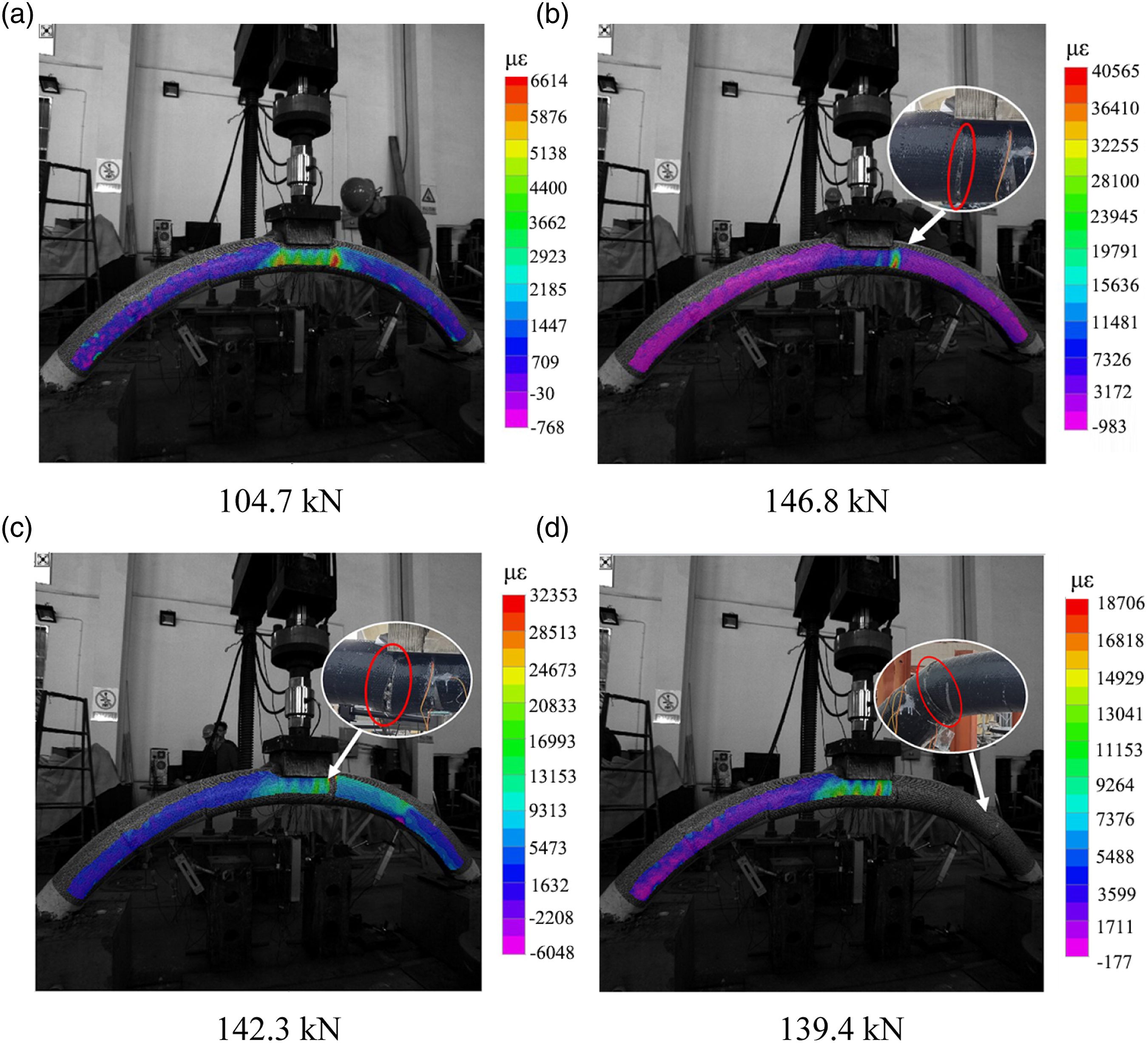
Load vs. displacement curves
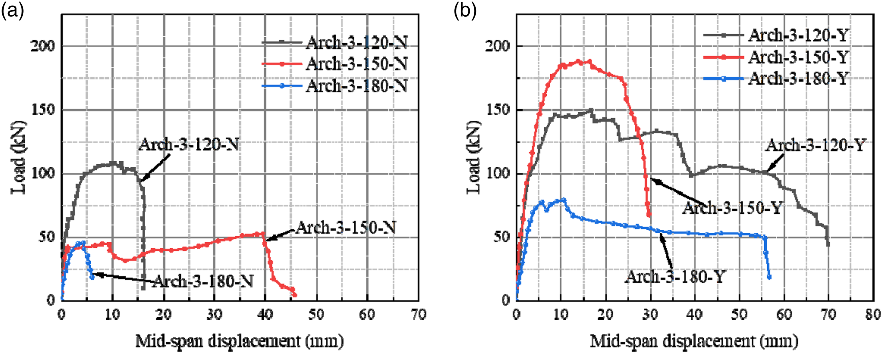
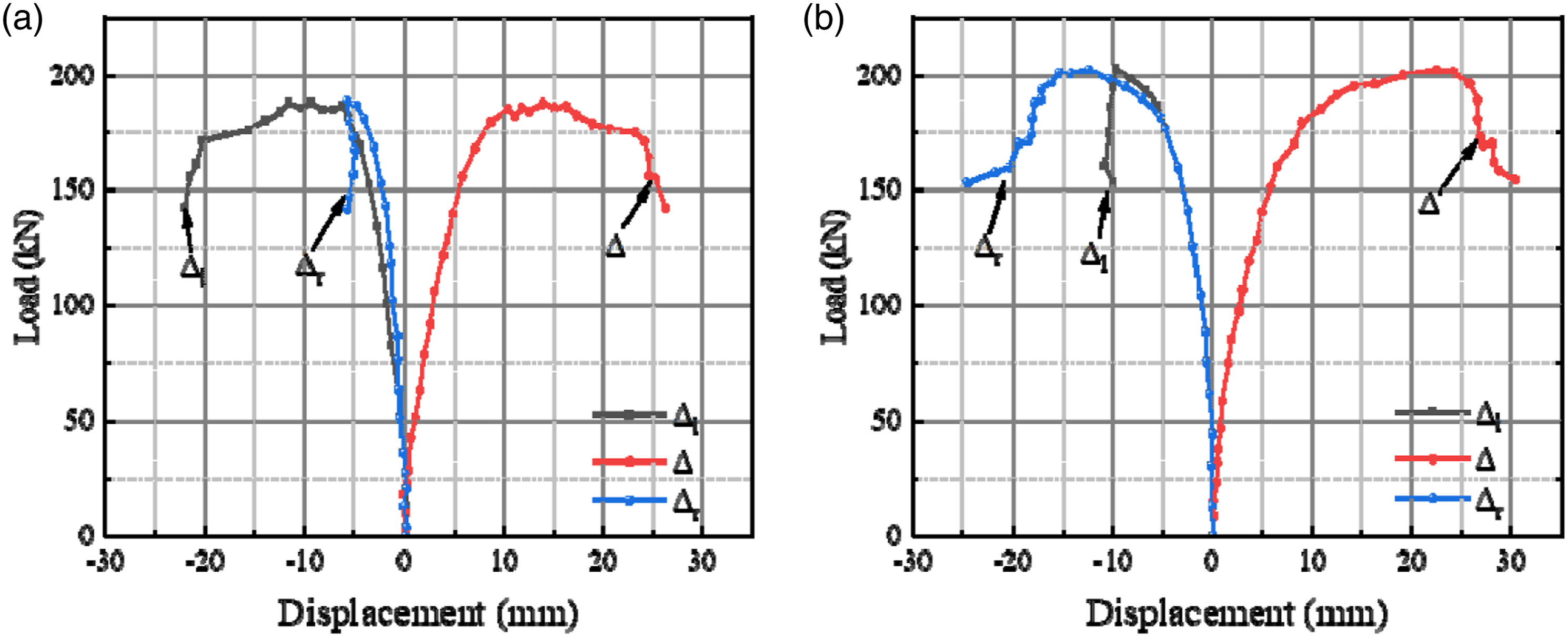
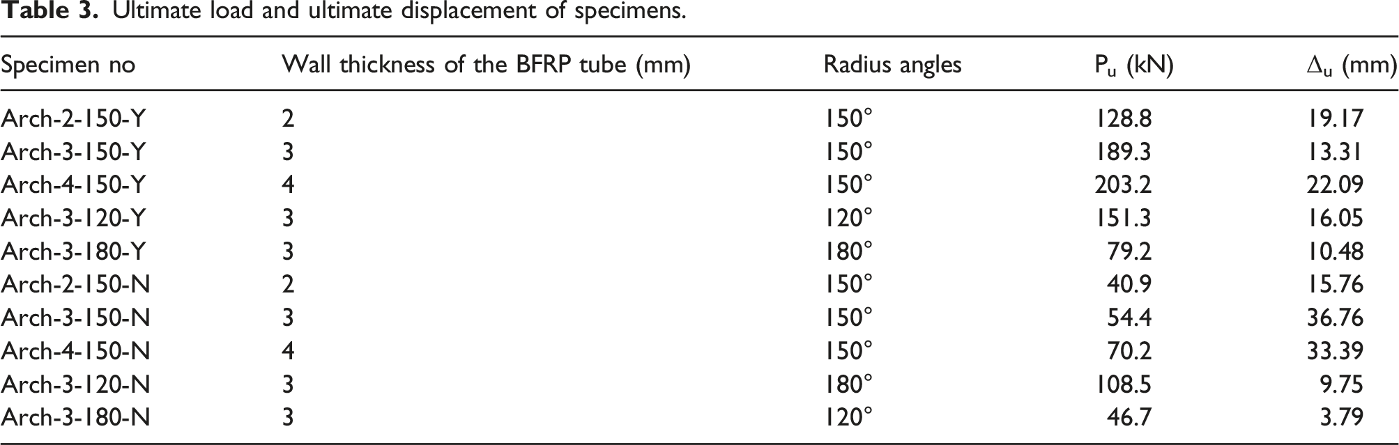
The load–displacement (P-Δ) curves of the arch specimens are shown in Figure 9, Figure 10 and Figure 11. The ultimate load and corresponding ultimate mid-span displacement of each specimen are shown in Table 3, where the Pu represents the ultimate load and the Δu represents the ultimate mid-span displacement. The radial displacements at the left and right quarter span are defined as Δl and Δr, respectively. P-Δ curves of specimens with different BFRP tube thicknesses: (a) Arch-2(3/4)-150-N and (b) Arch-2(3/4)-150-Y. P-Δ curves of specimens with different radius angles: (a) Arch-3-150(120/180)-N and (b) Arch-3-150(120/180)-Y. Representative load-radial displacement curves at quarter spans: (a) Arch-3-150-Y and (b) Arch-4-150-Y. Ultimate load and ultimate displacement of specimens.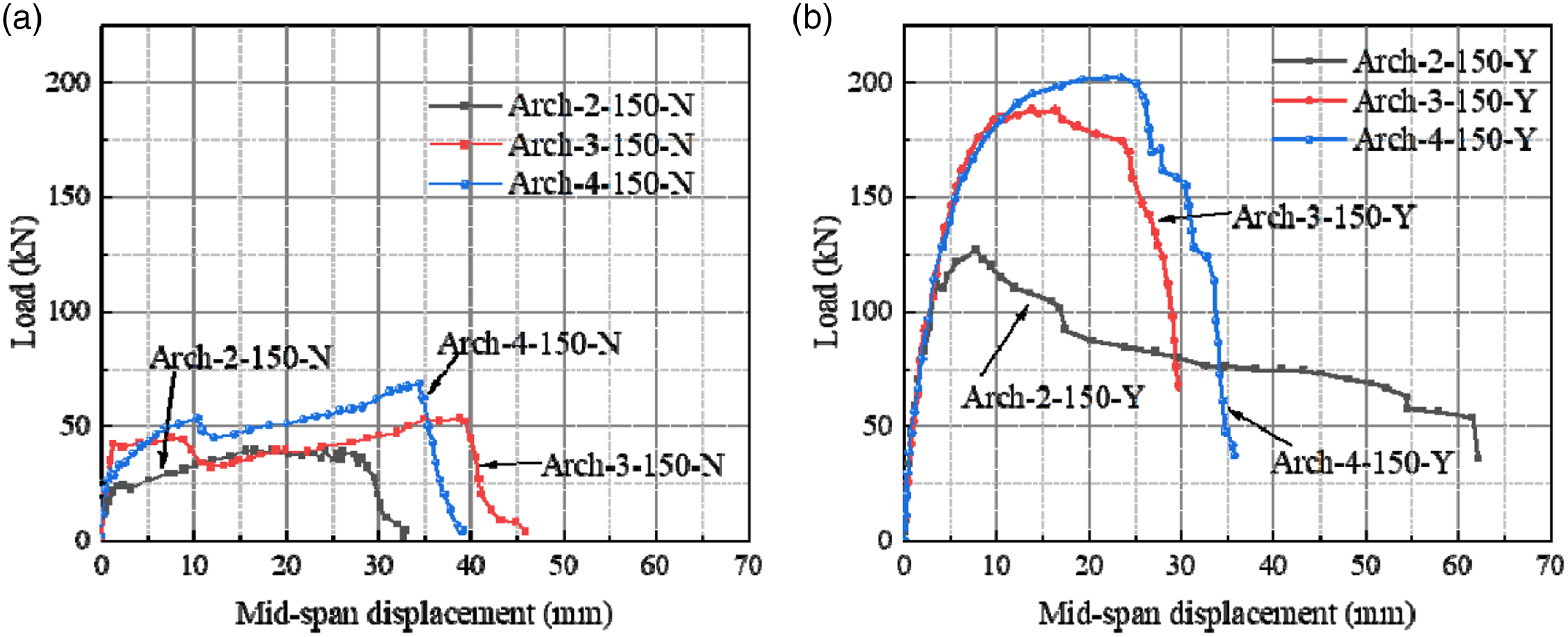
Load vs. mid-span displacement curves
The effects of the wall thickness of the BFRP tube and pre-bonded BFRP bars on the P-Δ curves are shown in Figure 9. As shown in Figure 9(a), the P-Δ curves were approximately linear in the early stage of loading. With the increase of load, the specimens entered the cracking damage stage, the tensile stress at the bottom of the arch gradually increases, and when the axial tensile stress in the BFRP tube exceeded its ultimate tensile strength, it was ruptured, and the load was reduced. With the development of cracks at the bottom of the mid-span arch and the outer side of the quarter span arch, and the rigid connection turned into hinge connection at the crack location, and the load could still be maintained and continued to increase by a small amount. Finally, the arch fractured at the quarter of the span because the cracks developed too large and formed a huge gap. In addition, it can be seen from Figure 9(a) that increasing the wall thickness of the BFRP tube could delay the initial damage and increase the ultimate bearing capacity of the specimen. Compared with the Arch-2-150-N specimen, the ultimate bearing capacities of Arch-3-150-N and Arch-4-150-N specimens increased by 33.1% and 71.7%, respectively.
As can be seen from Figure 9(a) and Figure 9(b), the pre-bonded longitudinal BFRP bars significantly increased the ultimate bearing capacity of the arches. For the specimens with a wall thickness of 2 mm, 3 mm, and 4 mm, the pre-bonded BFRP bars increased the ultimate bearing capacity by 215%, 248%, and 189%, respectively. Besides, as can be seen from the curves in Figure 9(b), the P-Δ curves of Arch-2-150-Y, Arch-3-150-Y, and Arch-4-150-Y were nearly coincident at the early stage of loading, which indicated that the wall thickness of the BFRP tube had little effect on the global rigidity of the specimens. The Arch-3-150-Y and Arch-4-150-Y specimens nearly entered the plastic stage at the same time, and their P-Δ curves were coinciding when the value of Δ was less than 10 mm. After that, the Arch-3-150-Y specimen approached the ultimate load, while the load of the Arch-4-150-Y specimen, which had thicker wall thickness, could still increase. The load values of the Arch-3-150-Y and Arch-4-150-Y specimens declined rapidly after reaching the peak point, which showed a brittle failure mode. While the curve of the Arch-2-150-Y specimen decreased relatively slowly after reaching the peak point. Combined with the failure mode as shown in Figure 6(a), it is believed that this was due to the premature damage at the left half of the span, resulting in a lower bearing capacity; meanwhile, the relatively low damaged arch body on the right side provided a continuous bearing capacity in the later stage of loading.
The effect of the radius angles on the P-Δ curve is shown in Figure 10. As shown in Figure 10(a), for arches without pre-bonded BFRP bars, the ultimate bearing capacities decreased with the increase of the radius angle (i.e., the rise-to-span ratio). The change of the rise-to-span ratio resulted in a change in the stress distribution within the arch body. The P-Δ curves of Arch-3120-N and Arch-3-180-N specimens did not show a decreasing and then increasing trend as that of the Arch-3-150-N specimen. The Arch-3-120-N specimen was fractured at the mid-span and the two quarter spans simultaneously. while the fracture section of Arch-3-180-N was not centered (close to the edge of loading steel block), which led to poor integrity of the specimen, and the bearing capacity decreased rapidly after reaching the ultimate load, showing obvious brittle characteristics.
It can be seen from the comparison of Figure10(a) and Figure 10(b) that the enhancing effect of adding BFRP bars on bearing capacity was related to the radius angle. For example, after pre-bonded with BFRP bars, the ultimate bearing capacity of the specimen with a 150° radius angle was increased by 248%, while the ultimate bearing capacities of the specimens with a 120° and a 180° radius angle were only increased by 39% and 70%, respectively. It can be seen that the reinforcement form proposed in this paper has the best enhancement effect on the specimens with a 150° radius angle. The internal force distribution in the arch body will change due to formation of concentrated cracks, and the bending moment distribution of the arch body is relatively more uniform at an angle of 150°. At the angle of 180° because the main cracks at the arch shoulder are too close to the main crack in the middle span, the damage in the later stage of the failure is more concentrated in a small area of the middle span. At the angle of 120°, when the failure occurs, the triangular diagonal bracing effect of the arch cannot be exerted due to the small arc, and the failure is controlled by bending.
Load vs. radial displacement curves at the quarter spans
Figure 11 shows the typical load vs. radial displacement curves at the quarter spans (the mid-span displacement is also given for comparison). Here, the Arch-3-150-Y and Arch-4-150-Y specimens are taken as examples. As can be seen, in the whole test process, the displacements at the two quarter points were all negative, and the two curves were close to or nearly coincident before approaching the ultimate load. This phenomenon indicated that the deformation of the Arch-3-150-Y and Arch-4-150-Y specimens was symmetrical, and the stresses generated in the arch body were also symmetrical.
Load vs. strain curves
Load vs. longitudinal strain curves
Figure 12(a) shows the relationships between the load and longitudinal strain of the top and bottom surfaces of the representative Arch-3-150-Y specimen. The strain increased linearly with the load at the initial loading stage. The arch bottom at the quarter points was compressed, and the bottom of the arch at the mid-span and the top of the arch at the quarter points were tensioned. Among them, the longitudinal strain of the bottom of the arch at the mid-span had the fastest increasing rate. With the cracking of the BFRP tube at the bottom of the mid-span, the strain gauge at this location was failed. When the bottom of the arch in the mid-span was cracked and destroyed, the internal stress in the arch body was continuously redistributed. The strain growth rate on the tension side and the compression side at the quadrant point gradually accelerated, and the growth rate of the strain on the tension side was greater than that of the compression side. Figure 12(b) shows the relationships between the load and longitudinal strain of the arch central axis of the representative specimen Arch-3-150-Y. It can be seen that the increasing rate of longitudinal strain in the mid-span was significantly higher than that in the quarter points. Longitudinal strain of the Arch-3-150-Y specimen: (a) top and bottom surfaces and (b) central axis.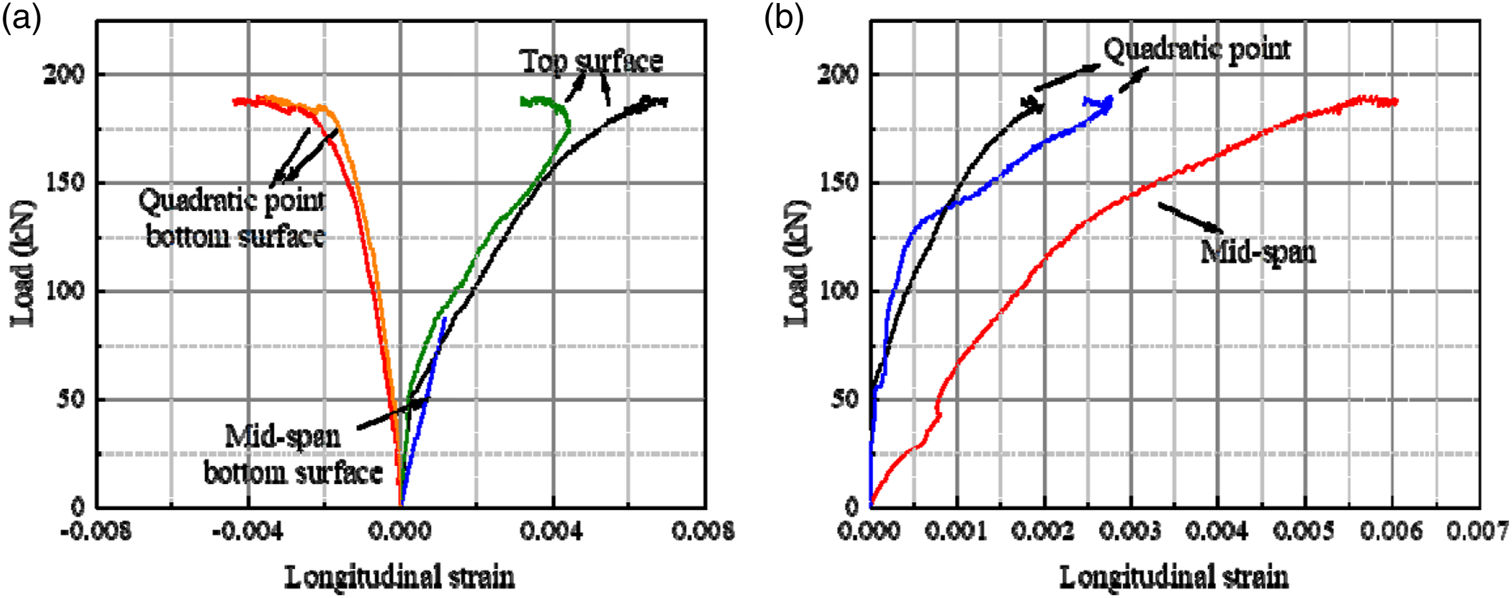
The test results of the surface strains of another representative specimen Arch-4-150-Y are shown in Figure 13. It can be seen that the law of the curves was similar to that of the Arch-3-150-Y specimen, which has a slightly thinner wall thickness. The difference was that the increasing rate of the longitudinal strain of Arch-4-150-Y at the bottom of the mid-span was not significantly greater than that at top of the arch body of the quarter spans, which means that increasing the wall thickness reduced the strain development rate. Figure 13(b) shows the longitudinal strain of the Arch-4-150-Y specimen along the arch central axis. It can be seen that the strain at the mid-span position was greater than that at the quarter points. Compared with the Arch-3-150-Y specimen, the strain values at the mid-span position under the same load were also significantly reduced. Longitudinal strain of the Arch-4-150-Y specimen: (a) top and bottom surfaces and (b) central axis.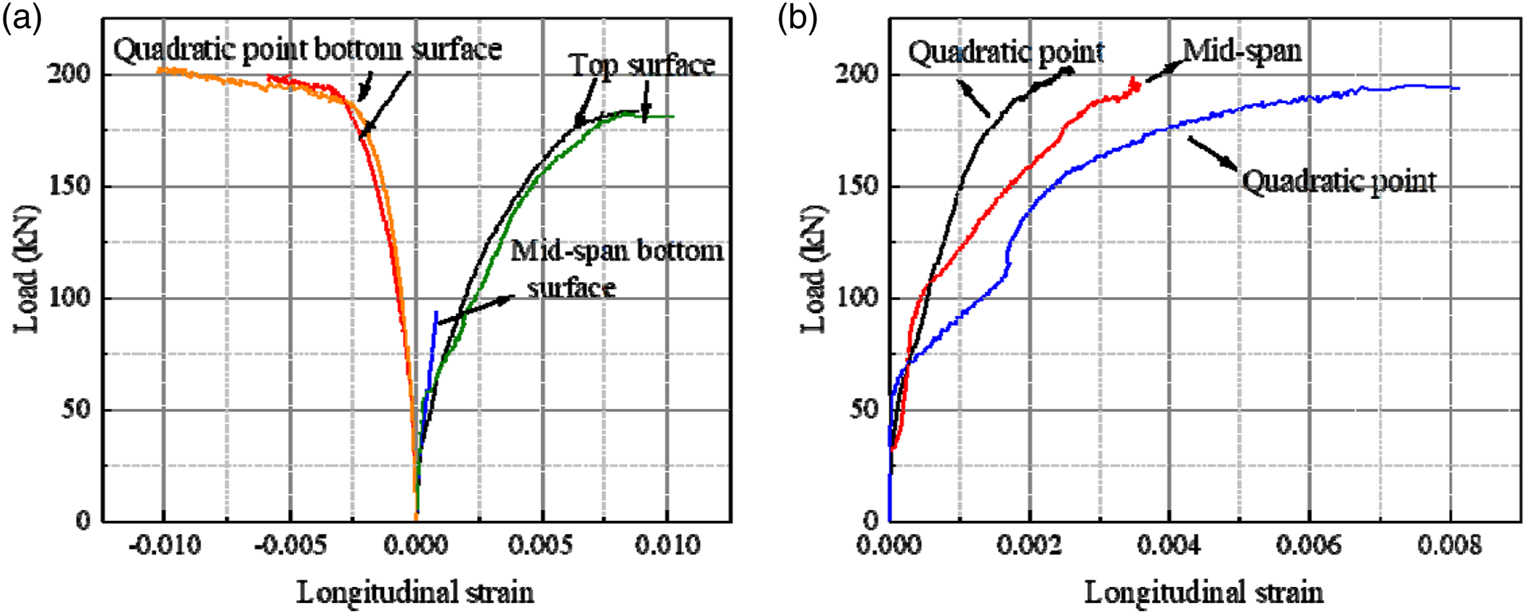
Load vs. circumferential strain curves
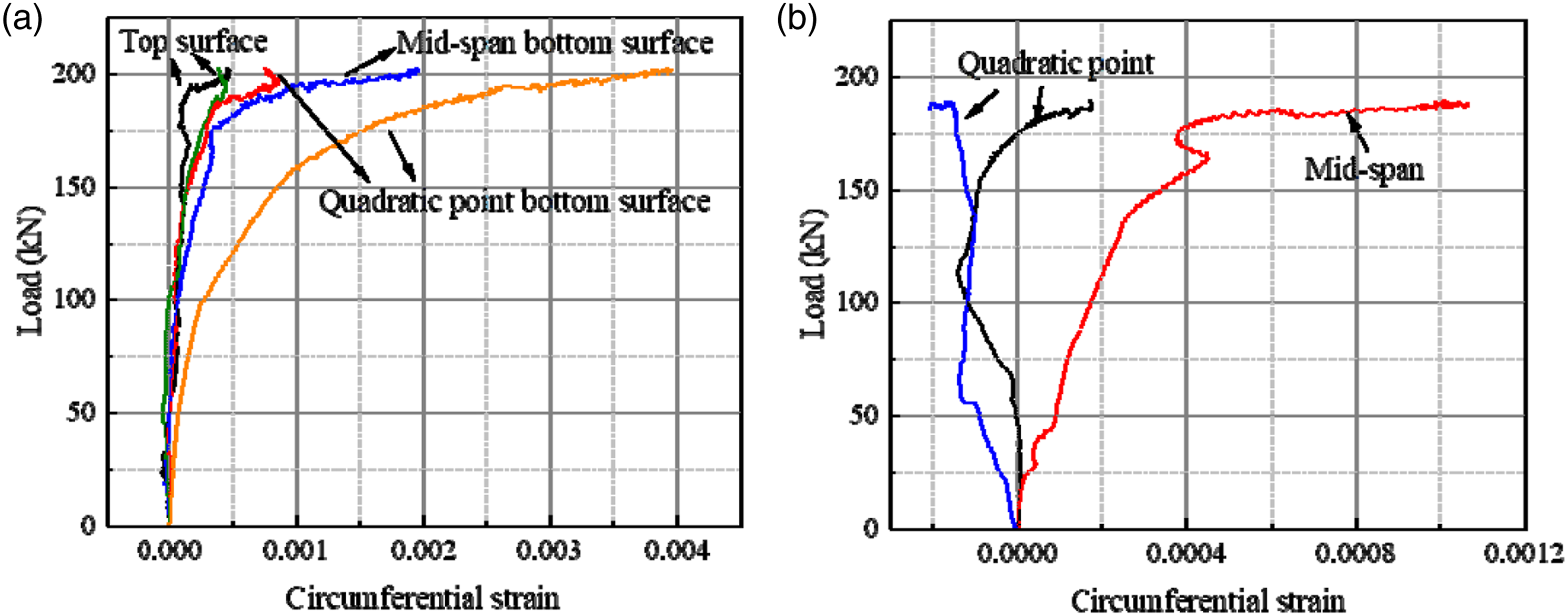
Figure 14 and Figure 15 show the load vs. circumferential strain curves of representative specimens Arch-3-150-Y and Arch-4-150-Y. Comparing Figure 14 and the above Figure 12, it can be seen that the circumferential strains of the Arch-3-150-Y specimen at different positions were all smaller than the longitudinal strains. This is because, in this test, the loading method was single-point concentrated loading. The arch was subjected to compression and bending during the test, and the bending moment had a greater impact on the deformation and failure of the arch. The good mechanical properties in the hoop direction had not been fully utilized. In Figure 15, because of the increase in the wall thickness of the BFRP tube, the hoop strains of the Arch-4-150-Y specimen were lower than those of the Arch-3-150-Y specimen under the same load levels. This phenomenon showed that increasing the wall thickness of BFRP tube could also suppress the increase of hoop strains. Circumferential strain of the Arch-3-150-Y specimen: (a) top and bottom surfaces and (b) central axis. Circumferential strain of the Arch-4-150-Y specimen: (a) top and bottom surfaces and (b) central axis.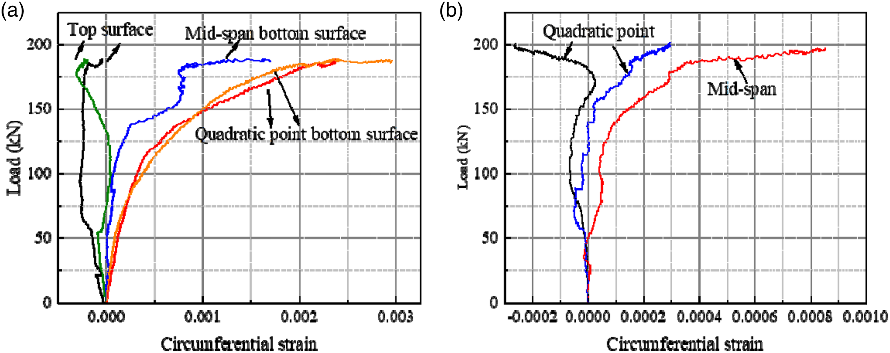
Change of the arch shape
Taking Arch-3-120-N and Arch-3-120-Y specimens as examples, the change of arch shape with load is introduced based on the data tested by the DIC technology. As shown in Figure 16, 14 points on the arch axis were selected to draw the arch shape. To more clearly distinguish the arch shape under different loads, the displacement values in the figures were magnified by 30 times. It can be seen from Figure 16(a) that the displacement of the Arch-3-120-N specimen remained basically unchanged at the initial stage of loading. When the load was less than 49.6 kN, only a partial region close to the loading head occurred slight vertical displacements. When the load reached 74.3 kN, the displacements were significantly increased. After the specimen reached 98.5 kN, the BFRP tube was cracked, and the displacement developed rapidly within the range of ±750 mm in the middle of the span. Figure 16(b) shows the displacement values of the Arch-3-120-Y specimen. The change rule was similar to that of the Arch-3-120-N specimen at the initial loading stage. However, due to the existence of the pre-bonded BFRP bars, the mid-span displacement of the Arch-3-120-Y specimen when it entered the plastic phase was increased by 71.3%. In addition, the displacements of the Arch-3-120-N specimen developed symmetrically on the left and right sides of the arch before entering the plastic stage, while the Arch-3-120-Y had a clear tendency to lean to one side. Due to the existence of the pre-bonded FRP bars, the main cracks at the mid-span appeared randomly at one side of the two edges of the loading steel block, resulting in the inconsistent failure time at the left and right quadratic points of the specimen. This is the reason why the displacements of specimens with FRP bars developed unsymmetrically. Change of the arch shape of representative specimens: (a) Arch-3-120-N and (b) Arch-3-120-Y.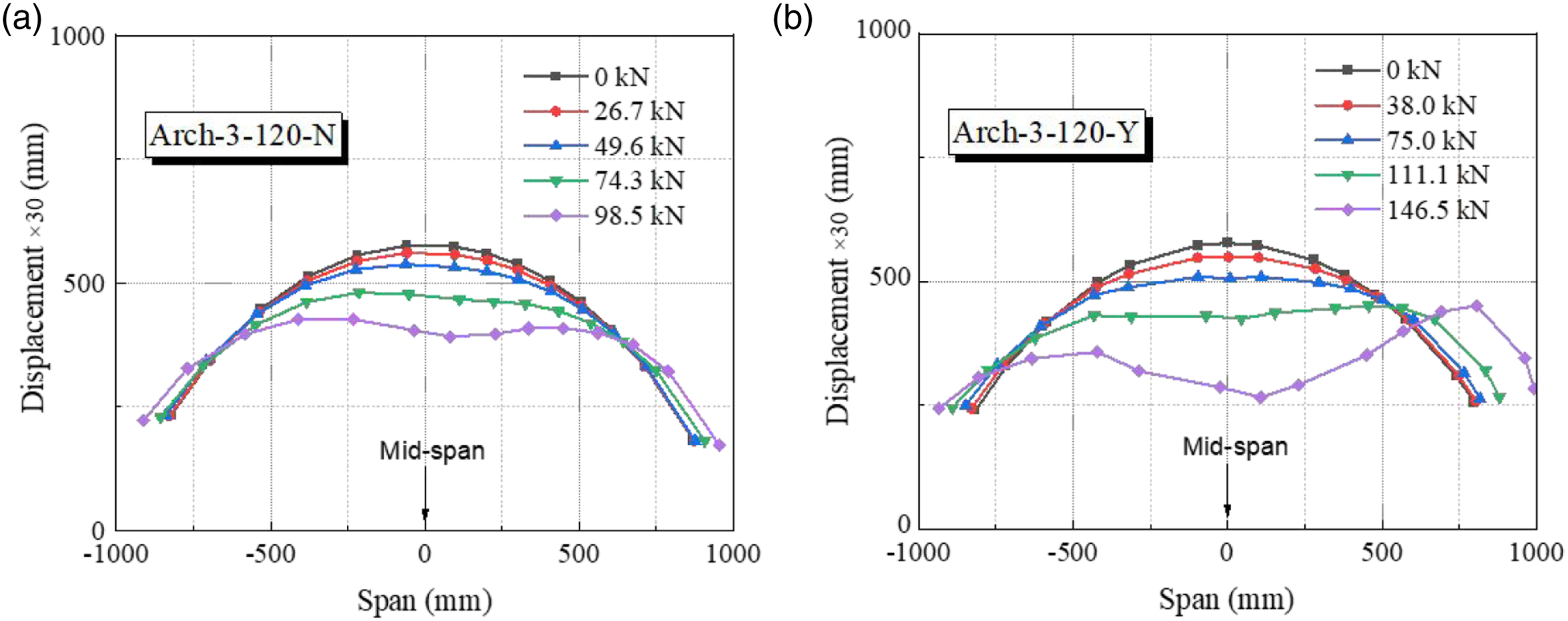
Conclusions
In this paper, a new type of SWCC-filled BFRP tubular arches that is suitable for the marine environment was proposed. Ten arch specimens with different BFRP tube wall thicknesses (2 mm, 3 mm, and 4 mm), different radius angles (120°, 150°, and 180°), and with or without pre-bonded longitudinal BFRP bars) are tested by monotonic loading. Based on the research of this paper, the following main conclusions are drawn: (1) For the arches with a radius angle of 150° and without pre-bonded BFRP bars inside, the failure modes were the fracture of the arch body. After the first cracking in the middle of the span, the bearing capacity decreased slightly. Subsequently, cracks of varying degrees appeared at the middle and the left and right quadratic points of specimens, and the rigid connection turned into hinge connection at the cracking section, so the bearing capacity increased slightly. In addition, as the wall thickness of the BFRP tube increased from 2 mm to 3mm and 4mm, the ultimate bearing capacity increased by 33.1% and 71.7%. (2) For the arches containing pre-bonded longitudinal BFRP bars, the first cracking of the specimens was transferred from the mid-span section to the section close to the edge of the loading steel block due to the combined bending-shear force. The existence of BFRP bars significantly improved the ultimate bearing capacities of the arches. For the specimens with a radius angle of 150° and a wall thickness of 2 mm, 3 mm, and 4 mm, the improvements were 215%, 248%, and 189%, respectively. (3) As the radius angle of the arches increased, the ultimate bearing capacity gradually decreased. Due to the excessively large radius angle of the Arch-3-180-N specimen, the failure mode changed from bending failure to bending-shear coupled failure, and the ultimate load-bearing capacity decreased significantly and showed obvious brittleness characteristics. For specimens with radius angles of 120° and 180°, the additional BFRP bars only increased the ultimate bearing capacity by 39% and 70%, while for specimens with a radius angle of 150°, the improvement was 248%, which was most obvious.
In addition, it should be noted that the preparation process of BFRP tubular arches with BFRP longitudinal bars pre-bonded in this paper can be further optimized. In the subsequent industrial production, a customized steel inner formwork with grooves can be used instead, which will be more efficient.
Footnotes
Declaration of conflicting interests
The author(s) declared no potential conflicts of interest with respect to the research, authorship, and/orpublication of this article.
Funding
The author(s) disclosed receipt of the following financial support for the research, authorship, and/or publication of this article: This work was supported by the financial support from the Natural Science Foundation of Jiangsu Province (BK20190369 and BK20191146), the National Natural Science Foundation of China (Grant No:51908118, 51838004, and 52078127), and the “Zhishan” Scholars Programs of Southeast University.