
Abstract
Motivated by a curiosity to explore the behavior of innovative arch structures enabled by the use of fiber-reinforced polymer (FRP) composites, this paper proposes a theoretical model built upon an enhanced formulation of the deflection method, broadening its scope to large-curvature problems. Traditionally, the deflection method approximates curvature as the second-order derivative of deflection, a simplification valid only for small curvatures. This limitation poses a challenge when applying the deflection method to problems involving large curvatures, a characteristic inherent in FRP-enabled arches where significant curvatures arise either initially or due to deformation. The enhanced formulation at the core of the proposed model addresses this challenge by incorporating a circular deflection function. This function posits that each deformed segment of the structural member can be represented by a circular arc, with its curvature and length related to the internal axial force and bending moment at the midpoint section of the segment. This feature facilitates the exact representation of curvature, offering the proposed model a unified approach capable of addressing both small- and large-curvature problems. The paper details the formulation and verification of the theoretical model, with an emphasis on its application to representative cases of FRP-enabled arches.
Introduction
Structural members with a longitudinal dimension much greater than their transverse dimensions are commonly referred to as one-dimensional members. These members can be categorized as straight members (e.g., beams and columns) or curvilinear members (e.g., curved beams and arches), depending on the shape of their longitudinal axis (i.e., centroidal axis). In structural analysis, one-dimensional members are commonly characterized by their centroidal axis, which serves as an important reference line for analyzing their behavior.
The deflection method is a widely used technique for analyzing one-dimensional members (Chen and Atsuta, 2007). This method effectively determines the deformed shape of the centroidal axis (i.e., deflection curve) of the member under prescribed loading and boundary conditions. Its effectiveness and accuracy have been demonstrated by successful implementations in straight members (e.g., Gao et al., 2021; Jiang and Teng, 2012a; Shen and Lu, 1983). In this method, the centroidal axis is discretized into many short segments with critical points known as grid points, which are typically located at the ends or midpoint of each segment. This discretization process transforms the continuous deflection curve problem into a discrete initial value problem where numerical procedures are used to solve for the unknown initial values, which are usually the support reactions or displacements at one end of the member.
The deflection method is traditionally based on the small displacement theory, which assumes that the deflection of the member is small compared to its length. This assumption enables simplification of the exact expression for curvature, provided that the centroidal axis of the member is initially straight or nearly so. In these cases, the curvature at any point on the deformed centroidal axis can be approximated as the second-order derivative of the deflection at this point. This simplification allows the deflection and slope at any grid point to be computed from known or assumed information (curvature, slope and deflection) at the previous one or two grid points, depending on the computation scheme employed. As a result, the deflection curve can be generated through a successive process, which involves section analysis at each grid point to determine the corresponding curvature required to proceed to the next grid point. Once the complete deflection curve is generated, boundary conditions are checked and necessary adjustments are repeatedly made to the initial guesses for the unknowns until the updated deflection curve satisfies the prescribed boundary conditions. Detailed descriptions of the conventional deflection method are available in various sources (e.g., Jiang and Teng, 2012b; Shen and Lu, 1983).
The use of simplified curvature representation in the conventional deflection method makes it appropriate for small-curvature problems, or more specifically, straight or slightly crooked one-dimensional members experiencing small displacement. However, its application becomes challenging when dealing with large-curvature problems, where the accuracy of the simplified curvature expression diminishes. Large curvatures in one-dimensional members can arise from geometry-related factors, such as the initial curvatures in arches and curved beams, or from deformation-induced factors, where the large curvatures are developed in initially straight members due to large displacement. In some cases, it can be a combination of both factors.
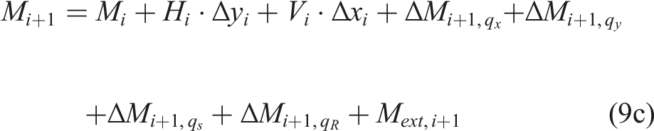
To address the challenge posed by large-curvature problems, this paper proposes a theoretical model based on an enhanced formulation of the deflection method. The enhanced formulation enables the model to offer a unified approach for handling both small- and large-curvature problems in one-dimensional members. The central insight of the enhanced formulation is that the deformed shape of each segment of the member can be approximated by a circular arc whose curvature and length are related to the internal axial force and bending moment acting on the segment’s midpoint section. This assumption allows the deformed centroidal axis to be represented by a continuous curve consisting of a sequence of circular arcs, rather than only discretely by the transverse displacement of the grid points. Therefore, the requirement of exact curvature representation is intrinsically satisfied in the model formulation.
The motivation behind developing the theoretical model largely stems from the authors’ curiosity in investigating the behavior of various forms of innovative arch structures enabled by the use of fiber-reinforced polymer (FRP) composites. These structural forms, which are referred to as FRP-enabled arches, are made possible or enhanced by the use of FRP. In their recent review (Xia et al., 2023), the authors identified two sub-categories of FRP-enabled arches: all-FRP arches and FRP-incorporating hybrid arches. The former takes advantage of FRP’s lightweight feature, making them ideal for small- or medium-scale applications where construction speed is a key consideration, such as lightweight footbridges and roofs (Sobrino and Pulido, 2002; Caron et al., 2009; Potyrala, 2011; Pyrzowski and Miśkiewicz, 2017; Bell et al., 2020; Liu et al., 2021, 2022). The latter is mainly intended for large-scale applications, such as long-span arch bridges and tunnel linings, where FRP is used in combination with concrete to address the issue of steel corrosion and to achieve excellent mechanical performance (Caratelli et al., 2016; Tang et al., 2020; Lee and Shin, 2010; Dagher et al., 2012; Jiang, 2020; Dong et al., 2022). FRP-enabled arches well exemplify large-curvature problems. In particular, FRP bending-active arches provide a unique case where the large curvatures are deformation-induced, as they utilize FRP’s outstanding elastic deformation ability to derive the arch shape through active bending of initially straight FRP profiles (Bessini et al., 2019; Caron et al., 2009; Habibi et al., 2022; Xie et al., 2023a).
The subsequent sections of this paper are structured as follows. First, the formulation of the theoretical model is presented. This is followed by its verification through comparisons with analytical results of linear elastic arches, serving as an example of large-curvature problems, and numerical results of slender FRP-confined reinforced concrete (RC) columns, serving as an example of small-curvature problems. Next, the verified model is applied to representative cases of FRP-enabled arches, including all-FRP arches and FRP-incorporating hybrid arches, to illustrate large-curvature problems involving both initially-born and deformation-induced curvatures. Comparisons with test results from these cases demonstrate the model’s ability to accurately predict the behavior of FRP-enabled arches.
Model formulation
Discretization process
Figure 1 illustrates an arch with an arbitrary shape defined by its centroidal axis Schematic of the theoretical model.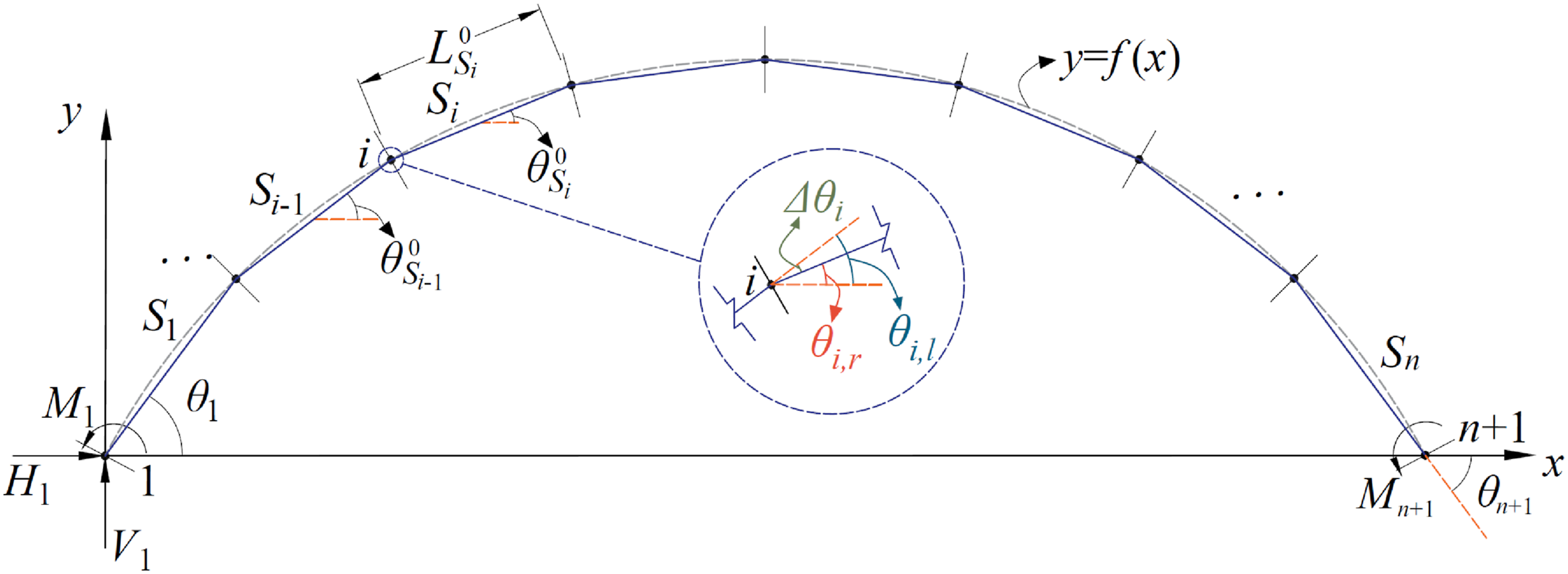
Deflection function
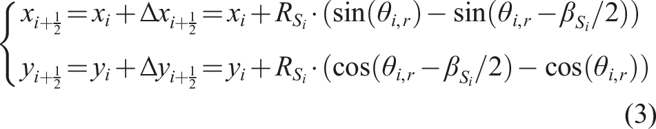
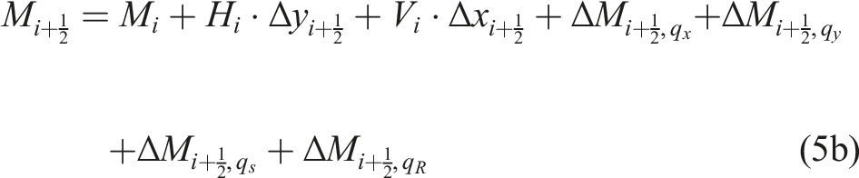
The defining feature that sets the model formulation apart from the conventional deflection method is its incorporation of a deflection function. This feature enables the model to provide a unified approach for handling small- and large-curvature problems. The deflection function is derived based on the assumption that, for a small segment, the variations in its internal axial force and bending moment are negligible so that they can be approximated as constants. When the bending moment is constant, the curvature is constant as well, meaning that the deformed segment must take on the shape of a circular arc. Moreover, the axial force being constant means a uniform axial strain along the length of the circular arc, so the change in length of the circular arc is a simple elongation or contraction of the initial segment length. Therefore, the task becomes choosing a representative point on the segment axis and using the axial strain and curvature induced by the internal axial force and bending moment at this point to generate a circular arc that represents the deformed segment shape. To perform this task, the segment midpoint is chosen as the representative point because it well characterizes the average deformation of the segment. An iterative procedure is used to determine the shape of the circular arc, as described below.
Suppose that during a given loading step, the calculation has reached segment Illustration of the deflection function: (a) Applied loads; (b) Midpoint determination; (c) Deformed segment shape. Internal forces caused by distributed loads.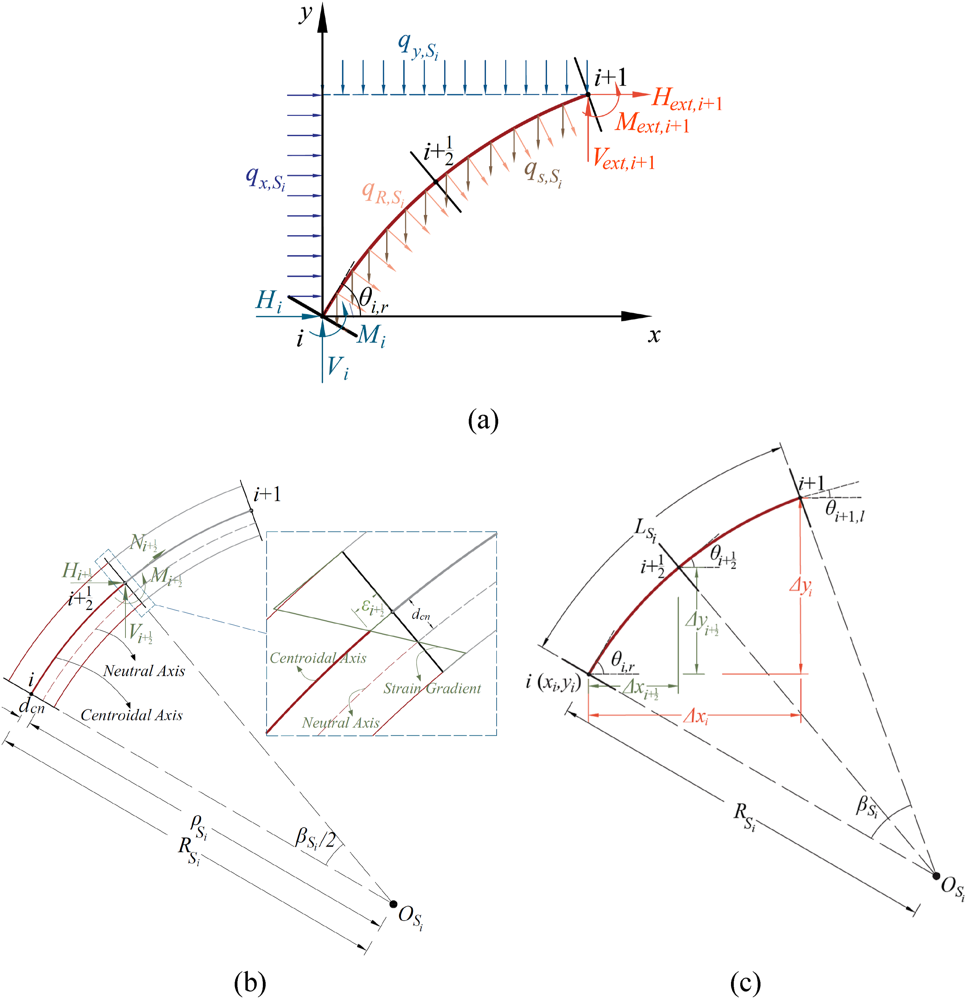
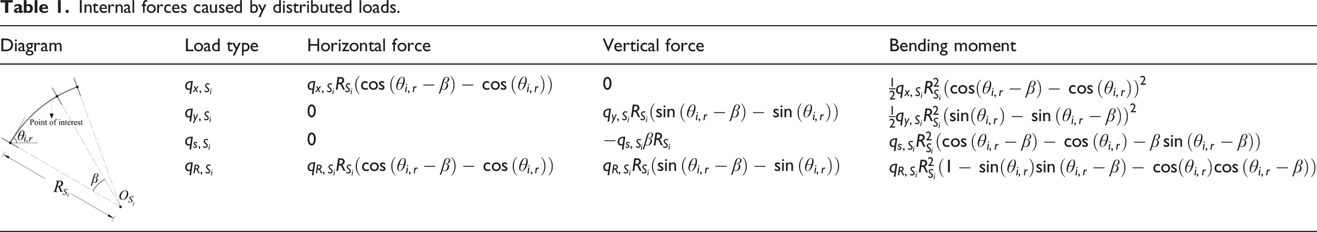
Consider the left half of the circular arc. In the first iterative step, the axial force and bending moment at the segment midpoint, 


The procedure then proceeds to the next iterative step using the updated 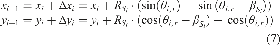


Finally, the internal forces at the 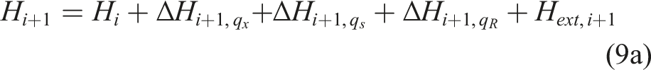

Solution procedure
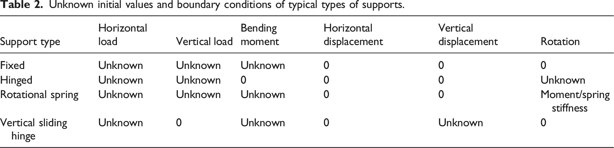
Unknown initial values and boundary conditions of typical types of supports.
It is expedient to present first the solution procedure for the simplest case, where the arch is subjected to a single load. In this scenario, the arch can experience failure either due to material limitations (i.e., material failure) or instability (i.e., stability failure), with the likelihood depending largely on its slenderness. Regardless of the failure type, the arch’s final deformation state is associated with material failure. Even when stability failure occurs first in the case of slender arches, post-buckling deformation can continue to develop as the load magnitude decreases until it reaches a point where material failure is triggered.
Therefore, the solution procedure adopts an incremental approach using the displacement-control technique. This technique is chosen over the load-control technique because it provides a unified approach to address both stability failure and material failure possibilities. In each incremental step, an increasing displacement value is applied at a selected grid point. The choice of the grid point may vary between incremental steps to ensure that the displacement at the chosen point continues to increase. The goal is to determine the correct load magnitude that induces the prescribed displacement at each step. In this approach, the load magnitude becomes an additional unknown, while the prescribed displacement serves as an additional boundary condition that must be satisfied by the computed deflection curve at the chosen grid point.
The initial step size, denoted as
Material failure is identified through section analysis performed at the midpoint section of each segment. When the calculated axial strain value at any point on the critical section exceeds the material’s strain capacity, it indicates that material failure has occurred. In response, the solution procedure is reverted to the previous incremental step and then resumes with a reduced increment of
When the arch is subjected to multiple loads, a loading regime needs to be prescribed to specify the ratios between the load magnitudes. One commonly used regime is proportional loading, where the ratios remain consistent throughout the entire loading process. By prescribing these ratios, the number of additional unknowns associated with the applied loads remains at one. Consequently, the load magnitudes can be determined by solving for the equal number of unknowns and boundary conditions. The remaining steps of the solution procedure follow the same approach as described for the single-load case.
Handling of intermediate hinge joints
Fixed, two-hinged and three-hinged arches are the three basic arch types. So far, the solution procedure has addressed the first two types. However, to apply the procedure to three-hinged arches, a slight modification is required in the model formulation to account for the behavior of the intermediate hinge joint. Consider Figure 2(c) and assume a hinge joint is located at the segment’s right end (
Handling of semi-rigid connections
Hinged and rigid connections represent idealized connection conditions. In practice, the actual connection condition often lies between these two extremes and requires modeling as semi-rigid connections. One common approach is to model them as rotational springs. Rotational springs can be used to represent both supports and intermediate joints. In either case, the bending moment acting on the spring induces an additional rotation 
The accuracy of the theoretical model is affected by several factors. These include the number of segments used to divide the member, the number of cross-sectional layers adopted in section analysis, and the tolerances set as convergence criteria. In this paper, all numerical examples employed 32 segments and
Verification
Comparisons with analytical results of linear elastic arches
The theoretical model was verified using the analytical solution derived by Pi and Bradford for linear elastic arches (Pi and Bradford, 2009). Their solution represents a significant advancement over classical elastic arch theories (e.g., Timoshenko and Gere, 1963), as it accounts for the effect of pre-buckling deformations on the displacement and geometric stiffness of the arch. This consideration is particularly important for shallow arches, where pre-buckling deformations significantly influence the arch’s buckling behavior (Pi and Trahair, 1998).
The solution of Pi and Bradford (2009) is concerned with the specific loading scenario of elastic circular arches subjected to a uniform radial pressure (Figure 3(a)). In classical arch theories, this loading scenario results in a compression line coinciding with the arch’s centroidal axis. This implies a pure concentric compression stress state of the arch, neglecting the axial deformation caused by the axial compression force. As a result, the predicted buckling mode according to classical arch theories is bifurcation buckling (Timoshenko and Gere, 1963). However, when the effect of axial deformation is considered, the compression line deviates from the centroidal axis as the applied radial pressure increases, introducing bending moments to the arch. This deviation can lead to the arch buckling in either a symmetric snap-through mode or an anti-symmetric bifurcation mode (Pi and Bradford, 2009), as illustrated in Figures 3(b) and 3(c), respectively. The dominant buckling mode depends on factors such as arch slenderness, shallowness, and level of end restraint. Illustration of a circular arch subjected to a uniform radial pressure: (a) Arch configuration and loading condition; (b) Symmetric snap-through buckling mode; (c) Anti-symmetric bifurcation buckling mode.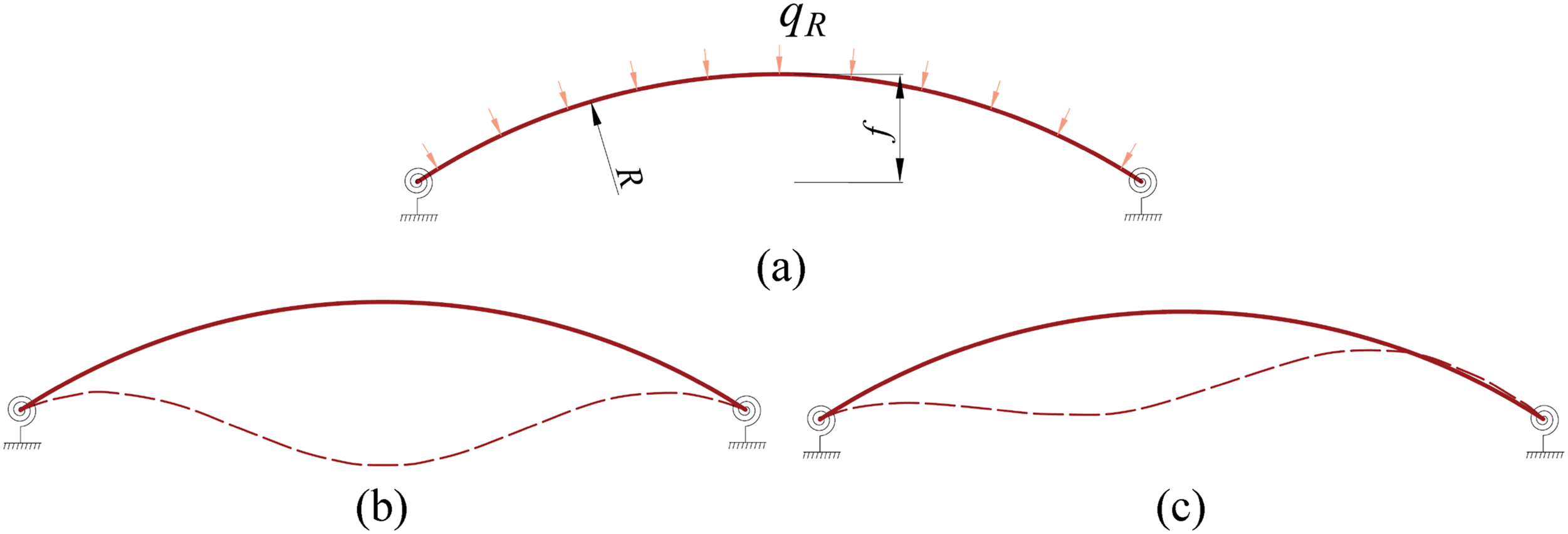
In the study of Pi and Bradford (2009), the supports of the arch were represented by two elastic rotational springs of equal stiffness, providing symmetrical restraint to the arch. The level of end restraint was indicated by the dimensionless flexibility of the rotational springs
Figure 4 presents a comparison between the load–deflection curves at arch crown, as predicted by the theoretical model and the analytical solution of Pi and Bradford (2009). These curves trace the variation of the normalized applied pressure Results of analytical verification: (a) 
The
Evidently, the predictions by the theoretical model match those by the analytical solution very well, except for the case shown in Figure 4(a) with
Comparisons with numerical result of slender FRP-confined RC columns
The theoretical model’s capability to address small-curvature problems is demonstrated through comparisons with the numerical results of a column model previously developed by the second author (Jiang and Teng, 2012b). This column model is based on the conventional deflection method and has been verified in Jiang and Teng (2012b), where its accuracy for slender RC columns and FRP-confined RC columns is also shown.
The numerical verification is based on referencing four slender FRP-confined circular RC columns tested by Tao et al. (2004), using the properties of these columns as inputs for both models. These columns, measuring 150 mm in diameter and 1260 mm in height, were reinforced with four 12 mm longitudinal steel bars and enveloped in a circumferential carbon FRP (CFRP) wrap with a nominal thickness of 0.34 mm. The concrete cover to the longitudinal steel reinforcement was 21 mm. All columns were pin-ended and subjected to equal load eccentricities at the two ends. The four columns were labeled C1-1R, C1-2R, C1-3R, and C1-4R, respectively, distinguished by their nominal load eccentricities (0 mm, 50 mm, 100 mm, and 150 mm). The material properties are as follows. The unconfined concrete strength was 48.2 MPa and the yield strength of the longitudinal steel reinforcement was 388.7 MPa. The CFRP wrap had an elastic modulus of 255 GPa and a hoop rupture strain of 1.32%. More details of these tests can be found elsewhere (Jiang and Teng, 2012b; Tao et al., 2004).
The load–deflection responses of the four columns were simulated using both the theoretical model and the column model of Jiang and Teng (2012b), with both models incorporating the same stress–strain models. Teng et al.’s (2009) design-oriented model, which is a refined version of Lam and Teng’s (2003) model, was employed to characterize the compressive stress–strain behavior of FRP-confined concrete, while the tensile strength of concrete was ignored. The longitudinal steel reinforcement was assumed to possess an elastic-perfectly plastic stress–strain curve.
Figure 5 illustrates a comparison between the load–deflection curves at column mid-height, as predicted by the two models. Following the approach of Jiang and Teng (2012b), all cases were modeled with an additional eccentricity of 7.5 mm added to the nominal load eccentricity. The two sets of theoretical curves exhibit excellent agreement, demonstrating the capability of the theoretical model in addressing small-curvature problems. Results of numerical verification.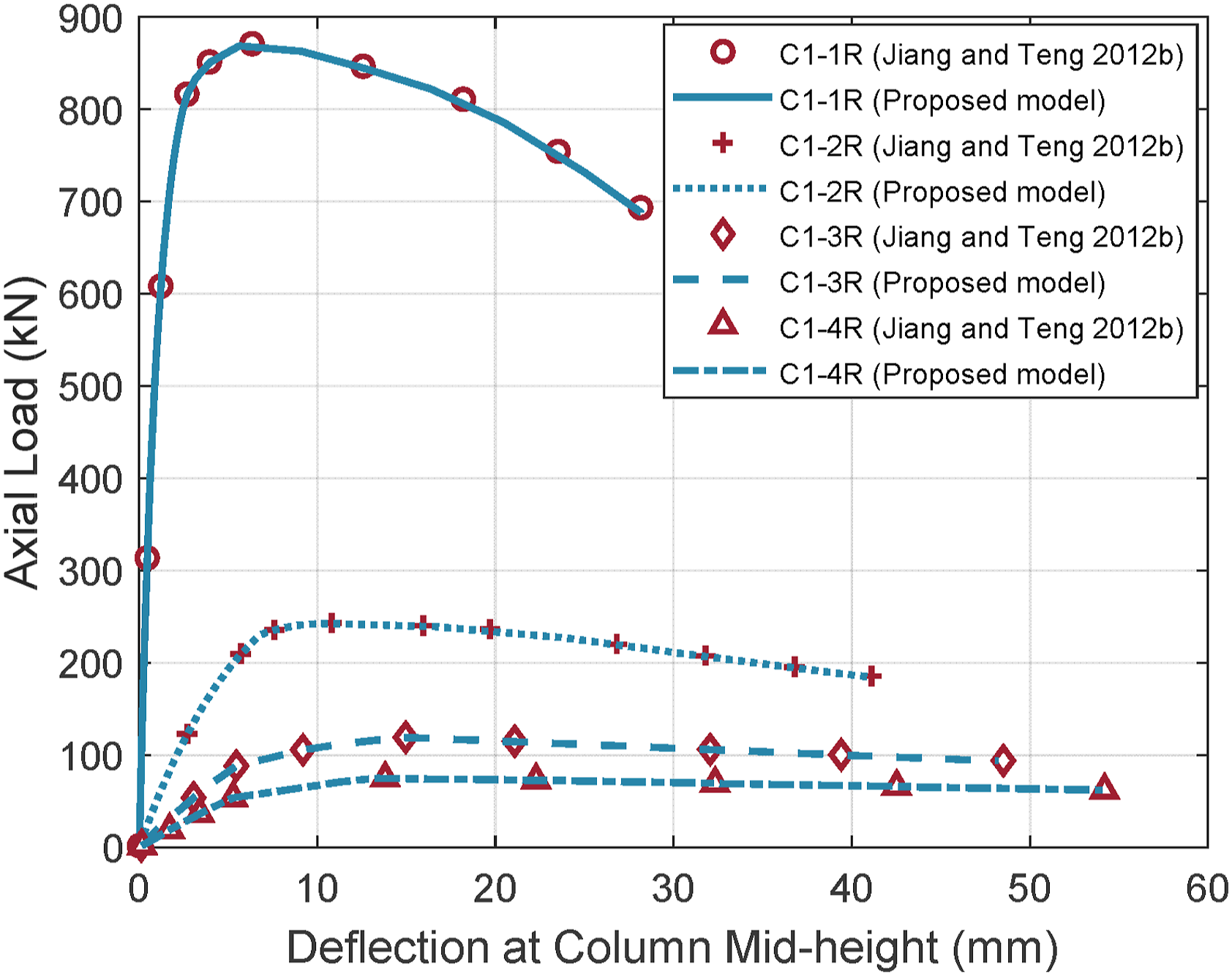
Application to FRP-enabled arches
FRP bending-active arches
Bending-active arches are a unique category of arch structures. They derive their curved shape from elastic bending of initially straight members (Lienhard et al., 2013; Xie et al., 2023b, 2024). FRP bending-active arches are suitable for use as rapidly assembled crossing bridges and supporting frames for temporary structures (Bessini et al., 2019; Caron et al., 2009; Habibi et al., 2022; Xia et al., 2023).
The tests conducted by Xie et al. (2023a) were employed as an example of all-FRP arches to validate the theoretical model. In their tests, the arch specimens were bent from straight CFRP strips with a cross section of 48.5 mm by 1.40 mm. During the bending process, the supports of the specimen allowed free rotation in the plane of the arch axis. Once the arch specimen was bent into place, the supports were transitioned to a clamped condition before receiving a concentrated load vertically applied at the arch crown. A total of 16 arch configurations were tested, with the main variables being the strip length and the span ratio (the ratio of arch span to strip length). The strip length was either 1.6 m or 2.0 m, each covering four span ratios (0.6, 0.7, 0.8 and 0.9). The CFRP had a flexural modulus of 127.5 GPa and a density of 1620 kg/m3.
Figure 6 displays a comparison between the experimental and predicted load–deflection curves at arch crown for all specimens. Each predicted curve was terminated when its predicted load aligned with the load at the final point of the corresponding experimental curve. As only the symmetrical snap-through buckling mode was observed in the tests, the modeling work simplified the arch specimen by considering only half of its original configuration. As a result, the support condition at the arch crown was modeled as a vertical sliding hinge (see Table 2). Additionally, the influence of gravity was considered, as it proved significant due to the large flexibility of the arch specimens. As illustrated in Figure 6, the predicted load–deflection curves closely align with their experimental counterparts. Comparisons with load–deflection curves of FRP bending-active arches: (a) L16 specimens; (b) L20 specimens.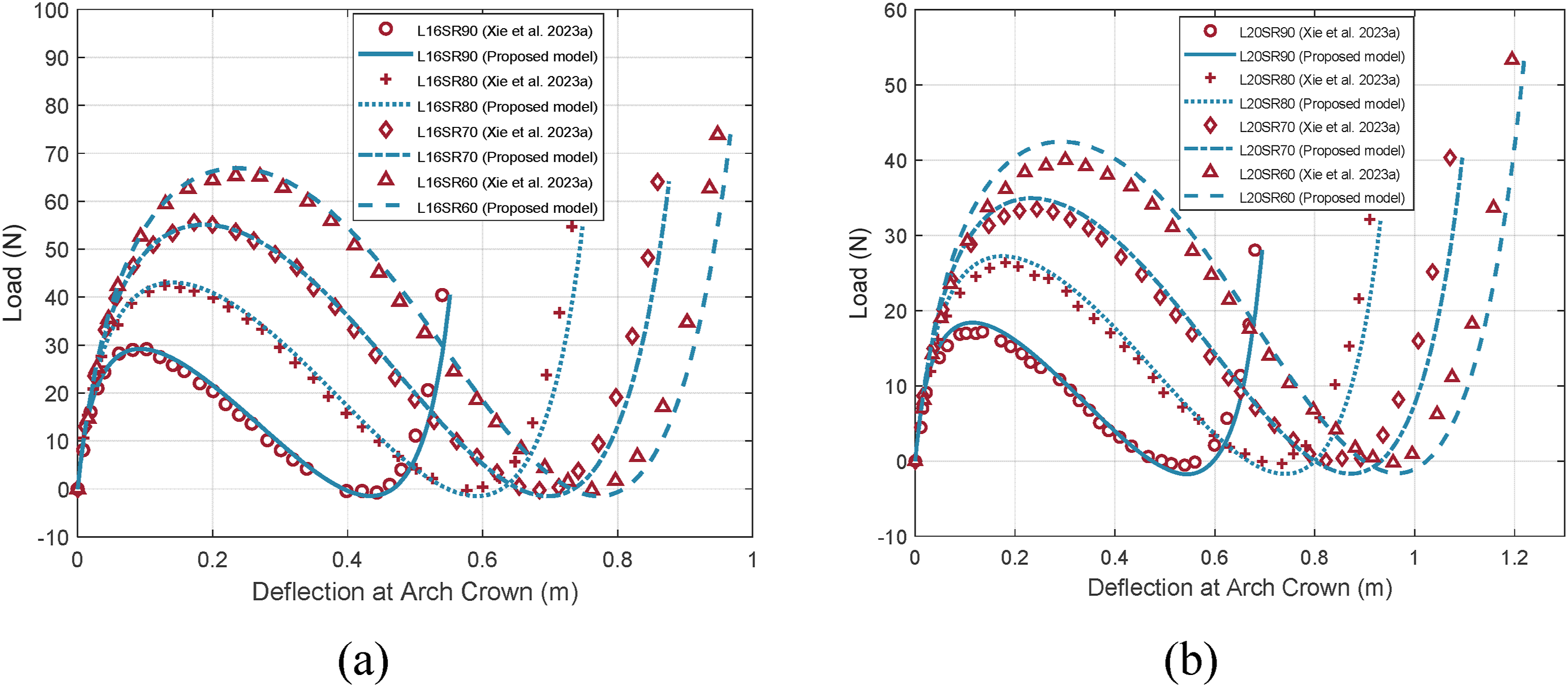
For illustrative purposes, Figure 7 provides a further comparison between the experimental and predicted deformed shapes of Specimen L16SR60. This specimen had a length of 1.6 m and a span ratio of 0.6. The comparisons were made at three representative states (State I, State II and State III), which correspond to the initial point, peak point and valley point of the load–deflection curve, respectively. Evidently, the theoretical model successfully reproduces the deformed shapes, demonstrating its accuracy in capturing the behavior of the arch specimens. Comparisons with deflected shapes of Specimen L16SR60.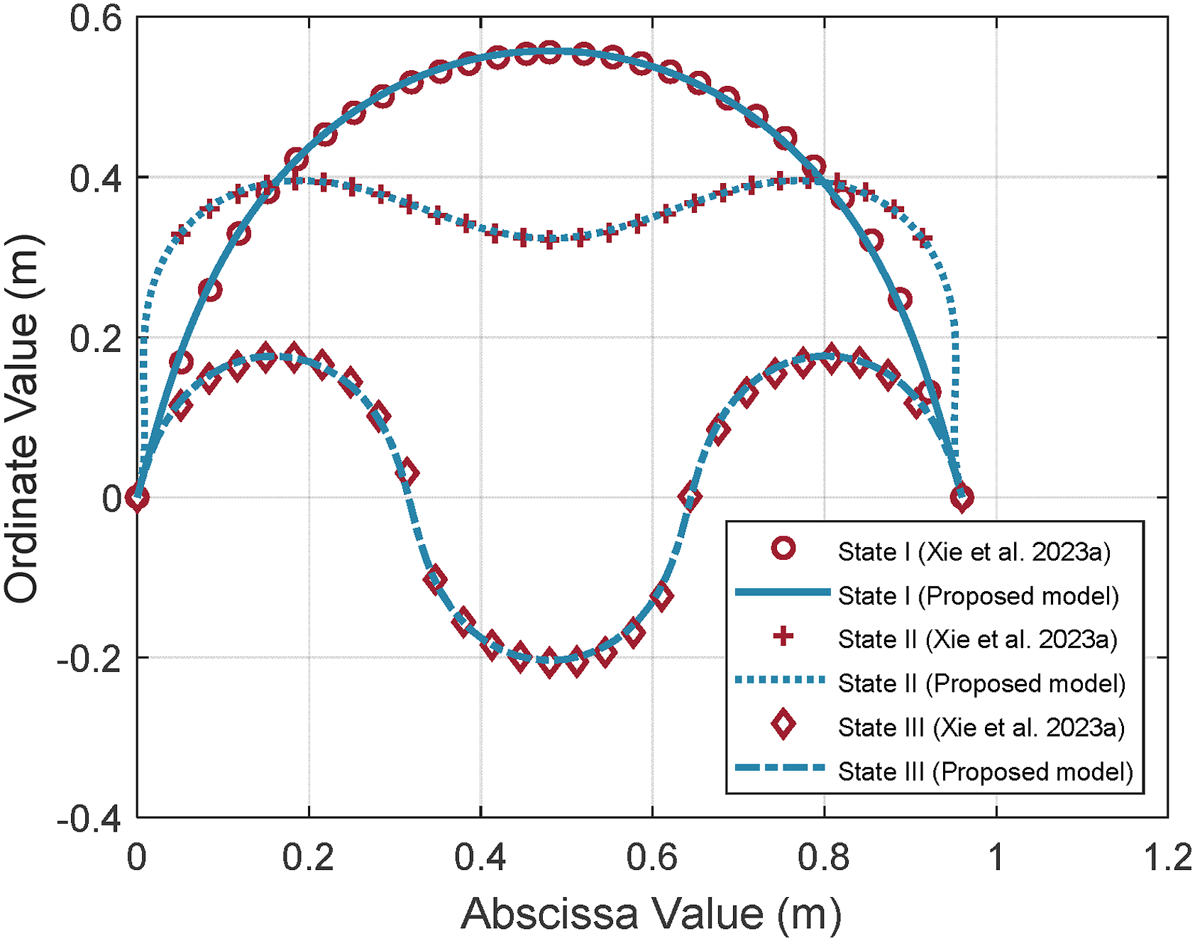
Concrete-filled FRP tubular (CFFT) arches
Geometrical and material properties of CFFT Arches.
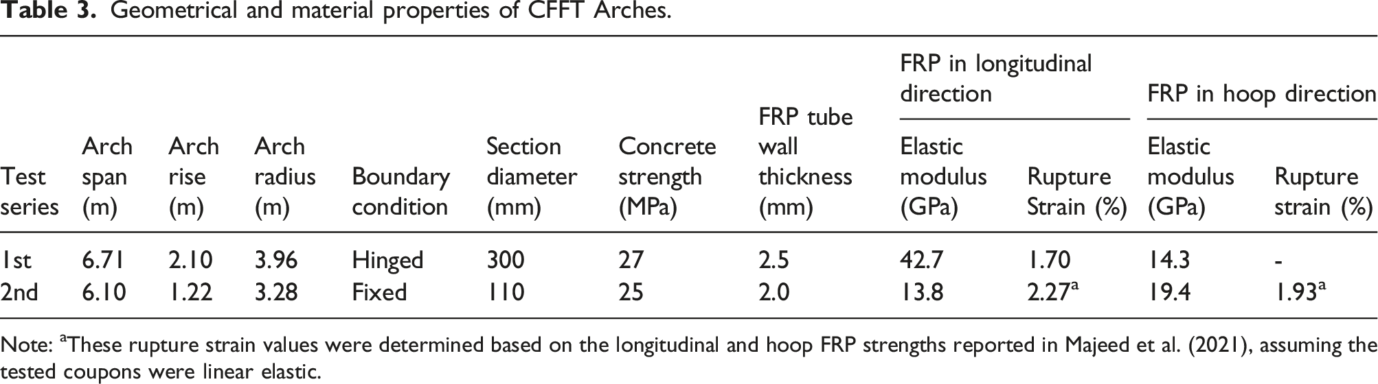
Note: aThese rupture strain values were determined based on the longitudinal and hoop FRP strengths reported in Majeed et al. (2021), assuming the tested coupons were linear elastic.
The first test series (Dagher et al., 2012) involved four nominally identical CFFT arches (A1, A2, A3 and A4) subjected to monotonic loading. These arch specimens were cast into RC footings at both ends, with the footings being pin-supported on the laboratory floor. For each arch specimen, the FRP tube comprised an inner layer of glass fibers and two outer layers of carbon fibers. By using different fiber orientations for the inner and outer layers, the resulting FRP tube exhibited significant stiffness in both the longitudinal and hoop directions. In the theoretical model, each RC footing was simplified as a rigid link, and the FRP tube’s behavior was assumed to be linear elastic in both the longitudinal and hoop directions. The interaction between the tube’s behaviors in these two directions was neglected in the analysis.
In the absence of test data, the elastic modulus and tensile strength of concrete were determined based on its compressive strength in accordance with the ACI standard (ACI 318-19, 2019). For consistency, Teng et al.’s (2009) model was again employed to describe the stress–strain behavior of FRP-confined concrete in compression. It should be noted that Teng et al.’s (2009) model requires the input of the FRP rupture strain. This value was assumed to be 2% as it was not reported in the original literature (Dagher et al., 2012). Varying the rupture strain in the range of 1∼3% showed a negligible influence on the model predictions because the failure of the arch specimens was not due to the rupture of the FRP tube in the hoop direction. The stress–strain curve of concrete in tension was assumed to be linear before cracking. The tension-stiffening effect was accounted for using the model proposed by Collins and Mitchell (1997). This model is a modification of Vecchio and Collins’s (1986) tension-stiffening model and has demonstrated a good predictive capability concerning moment-curvature relationships for CFFT flexural members in previous studies (Bannon et al., 2009; Fam, 2000). Full composite action was assumed between the FRP tube and the concrete core. Additionally, only half of the arch specimen was considered due to symmetry.
Figure 8(a) compares the experimental and predicted load–deflection curves at arch crown. Notably, Specimens A1 and A2 exhibited a less stiff initial response than Specimens A3 and A4. Dagher et al. (2012) attributed this difference to accidental damage prior to testing and initial imperfections. Therefore, the load–deflection curves of Specimens A3 and A4 are considered to better represent the true behavior of the arch specimens. These two curves are closely matched by the predicted curve. Dagher et al. (2012) reported that the failure of all arch specimens was due to longitudinal rupture of the FRP tube in the tension face, directly below the point of load application. Hence, the predicted curve terminates when the FRP tube reaches its longitudinal rupture strain. Comparisons with load–deflection curves of CFFT arches: (a) hinge-supported; (b) fixed.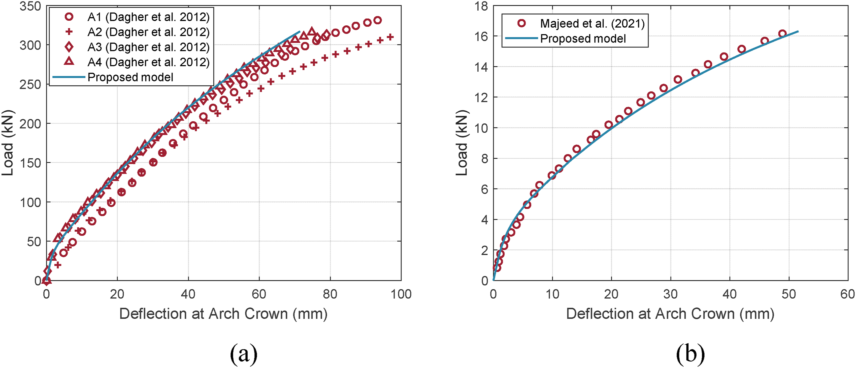
The second test series (Majeed et al., 2021) exclusively focused on a fixed CFFT arch with a more slender configuration. The FRP tube used in this test consisted of two layers of glass fibers, with each layer having a distinct fiber angle. The failure mode observed in this specimen was consistent with the one observed in the first test series. The modeling procedure for this specimen was similar to that used for the first test series, except for a variation in the support condition. As illustrated in Figure 8(b), the theoretical model accurately predicts the load–deflection response of this specimen.
Conclusions
This paper has been concerned with the formulation, verification and application of a theoretical model for one-dimensional members. Originally developed to address the challenges posed by large-curvature problems encountered in FRP-enabled arches, the model’s versatility enables its application to the broader range of general one-dimensional members. The work presented in this paper allows the following conclusions to be drawn: (1) The theoretical model is built upon an enhanced formulation of the deflection method. Its defining feature is the incorporation of a circular deflection function, which posits that each segment of the deformed centroidal axis can be represented by a circular arc whose curvature and length are related to the internal axial force and bending moment acting on the segment’s midpoint section. This feature facilitates the exact representation of curvature, distinguishing the proposed model from the conventional deflection method, where the simplified representation of curvature as the second-order derivative of deflection is valid only for small curvatures. Therefore, the proposed model represents a significant improvement over the conventional deflection method in that it offers a unified approach to address both small- and large-curvature problems. (2) Model verification was carried out through comparisons with both analytical and numerical results from the literature. The analytical verification focused on a large-curvature problem of linear elastic arches, while the numerical verification employed a small-curvature problem of slender FRP-confined RC columns, incorporating material non-linearity. The verification results demonstrated the correct implementation of the theoretical model and its equal capability in handling small- and large-curvature problems. (3) The performance of the theoretical model was evaluated against representative test results from FRP-enable arches, comprising two sub-categories: all-FRP arches exemplified by FRP-bending active arches and FRP-incorporating hybrid arches exemplified by CFFT arches. In the case of FRP-bending active arches, the large curvatures were induced by deformation, whereas in CFFT arches, the large curvatures were inherent in their initial configuration. The theoretical model demonstrated excellent accuracy in predicting the behavior of arches in both sub-categories, regardless of the source of the large curvatures.
Footnotes
Acknowledgments
The PolyU-ZJU Joint PhD Program is gratefully acknowledged for enabling the first author’s PhD journey under the joint supervision of the second and third authors.
Declaration of conflicting interests
The author(s) declared no potential conflicts of interest with respect to the research, authorship, and/or publication of this article.
Funding
The author(s) disclosed receipt of the following financial support for the research, authorship, and/or publication of this article: This work was supported by the National Natural Science Foundation of China (Project No.: 51778569) and the Hong Kong Research Grants Council (Project No.: T22-502/18-R).