
Abstract
Concrete structures where a harsh environment might induce corrosion of steel rebars, FRP (fiber-reinforced polymer) rebars may be utilized as a feasible substitute for steel bars. The compression performance of reinforced concrete (RC) columns having a mix of GFRP (glass FRP) and steel reinforcement, on the other hand, is unclear. The present study focuses on incorporating an inner steel tube in RC columns having GFRP rebars. The employment of GFRP rebars as vertical reinforcement of high tensile strength will be effective in resisting flexure, whereas the inner steel tube will carry the axial load. In this research, a testing campaign was carried out on square columns having dimensions of 250 × 250 × 1000 mm, wherein the columns were experimentally examined in the event of concentric and eccentric compression. The variables studied include (i) two rebar types, namely steel and GFRP, (ii) two diameters of vertical GFRP bars having almost the same percentage of reinforcement (1%-1.1%), and (iii) unblended versus hybrid (i.e., having a steel tube) reinforcement. The axial compression response of RC columns having almost the same percentage of GFRP rebars and a steel tube was not affected by the rebar diameters. However, it affected the eccentric compression behavior due to the change in the layout of the rebars. The use of a steel tube as internal reinforcement introduced ductility in the eccentrically loaded columns. Based on the section analysis, analytical models were developed for creating the P-M graphs for RC columns having GFRP bars combined with a steel tube used as internal reinforcement. The equations consider the compression response of GFRP bars. Incorporating the compressive capacity of GFRP rebars results in the expansion of the P-M interaction plots, thereby bringing the experimental curve into closer alignment with the envelope.
Introduction
The employment of FRP rebars in RC columns offers numerous advantages over traditional steel reinforcement. The non-corrosion, great ratio of resistance to weight, non-magnetic and non-conductive properties, and design flexibility of FRP bars make them a viable alternative for enhancing the response of beams (Abbas et al., 2023b; Almusallam et al., 1997; Zeng et al., 2023a) as well as columns (Alsayed et al., 1999). The utilization of FRP bars in compressive elements is still not favored owing to: (i) low elastic modulus as compared to steel rebars, (ii) low contribution in resisting compression, (iii) low ductility, and (iv) performance in compression not well established. Due to these disadvantages, which are mainly based on past studies on the old generation of GFRP rebars of low grade (Alsayed et al., 1999), ACI Committee 440 (2015) does not recommend using FRP rebars in compression members. However, based on later studies on new generations of GFRP bars, the ACI Committee is currently developing guidelines for the utilization of FRP rebars in columns parallel to ACI 318 (2019), which requires experimental data that is very limited.
De Luca et al. (2010) performed a testing study on full-scale concrete columns containing GFRP bars, focusing on their behavior under axial loads. The testing of six columns up to failure unveiled that GFRP-reinforced concrete columns exhibited ductile characteristics, displaying a slight reduction in load-bearing capacity. Failure modes included GFRP rupture, concrete damage, and the detachment of GFRP rebars from the concrete. These specimens showcased comparable axial load-bearing capacity and stiffness when compared to columns having traditional steel reinforcement.
Afifi et al. (2013) displayed results from compression tests performed on twelve circular RC columns of full scale. These columns had GFRP bars and spirals. Various factors were investigated, encompassing the type of reinforcement (steel against GFRP), the ratio of vertical FRP bars, the diameter of bars, and the pitch of transverse spirals. The outcomes highlighted similar responses between GFRP and steel RC columns. The vertical GFRP rebars carried an average resistance varying from 5% to 10% of the ultimate capacity. Utilizing GFRP spirals of smaller diameter at closer spacing led to improved ductility and enhanced confinement efficiency. Neglecting to account for the role of GFRP rebars resulted in an underestimation of the columns’ load-bearing resistance.
Tobbi et al. (2014) presented a prediction procedure for RC columns having vertical and lateral FRP reinforcement. The study involved experiments on RC columns having FRP reinforcement with varying configurations, measuring parameters like load-displacement response, failure modes, and strain distribution. Derived from the experimental findings, a strength model was proposed that considered the combined contribution of FRP bars and ties, incorporating factors such as concrete confinement, bond-slip behavior, and the interaction between FRP components.
In the research carried out by Fan and Zhang (2016), an experimental campaign was made into the response of inorganic polymer concrete columns having BFRP (basalt FRP) rebars when subjected to eccentric compression. The experiments showed that the concrete columns containing BFRP rebars demonstrated notable enhancements in load-bearing capacity, ductility, and energy absorption in comparison to unreinforced columns. The inclusion of BFRP reinforcement effectively counteracted the adverse impacts of eccentric loading, thereby enhancing the overall performance of the specimens.
Hadi et al. (2016) conducted a study to explore the response of HSC (high-strength concrete) columns containing GFRP bars in various loading scenarios. They analyzed key factors including the sort of reinforcement (GFRP against steel), the spacing of lateral reinforcement, and the loading conditions (four-point flexure, eccentric, and concentric) to comprehend their impact on the response of the columns. The findings demonstrated that when subjected to concentric axial compression, HSC columns having GFRP rebars had axial resistance comparable to their steel counterparts. Nevertheless, as the eccentricity increased, the ability of columns containing GFRP rebars to sustain axial loads decreased. Additionally, replacing the steel bars with a comparable amount of GFRP bars in HSC specimens led to an approximately 30% reduction in ductility under concentric loading. However, the study revealed that introducing closely spaced helices could significantly enhance the ductility and post-peak resistance versus the deformation performance of HSC columns having GFRP reinforcement.
In a later study, Hadi et al. (2017) explored the bahavior of circular HSC columns containing GFRP bars and helices. The objective was to explore how these columns perform under different loading conditions. Experiments were performed on circular specimens having GFRP rebars and helices, subjecting them to eccentric and concentric compression as well as lateral impact. Parameters like load capacity, deflection, strain, and failure modes were measured. The findings demonstrate that columns having GFRP reinforcement demonstrated high load resistance and superior performance in diverse loading conditions. The columns exhibited ductile behavior, gradually losing stiffness towards failure.
Khorramian and Sadeghian (2017) explored the behavior of short RC columns containing GFRP bars and tested in the event of eccentric compression. The study includes experiments on specimens with varying reinforcement ratios and eccentricity levels, analyzing parameters like load-displacement behavior, failure modes, and strain distribution. A mathematical model was also created, taking into account material nonlinearity, bond slip, and eccentricity. The analytical findings were compared with experimental findings, validating its accuracy. Sun et al. (2017) presented a testing campaign on the performance of RC columns containing GFRP bars and tested in the event of eccentric loading. The study examined the performance and failure characteristics of these columns through experimental tests. Various parameters, such as load-displacement response, failure modes, and strain distribution, are analyzed for RC columns having GFRP rebars with various reinforcement ratios and eccentricity levels. Guerin et al. (2018a) examined the influence of GFRP reinforcement ratio on the strength of RC columns. Experimental tests revealed that enhancing the ratio of vertical GFRP rebars enhances the strength and load-bearing capacity of the columns. An optimal GFRP reinforcement ratio exists to attain the highest resistance, beyond which the gains are minimal. Columns with higher reinforcement ratios exhibited improved ductility and resistance to sudden failure. Researchers in another study (Guerin et al., 2018b) examined the eccentric compression response in full-scale RC columns containing longitudinal and transverse GFRP reinforcement. Full-scale tests were conducted until failure, measuring load capacity, deflection, strain, and failure modes. The results demonstrated ductile behavior and a small loss of stiffness in RC columns having GFRP reinforcement and tested under eccentric loading.
Hadhood et al. (2019) examined the design recommendations for columns that were reinforced with GFRP rebars. Experiments were conducted on columns containing GFRP rebars to evaluate factors such as load resistance, deflection, strain, and failure patterns. The findings demonstrated that the current design guidelines tend to underestimate the resistance of columns containing GFRP bars. Additionally, the observed modes of failure differed from the anticipated ones. In order to enhance design methodologies, the researchers introduced adjusted equations derived from the experimental results, which offer a more accurate assessment of axial resistance.
In their study, AlAjarmeh et al. (2019a) investigated the characteristics of circular hollow columns containing GFRP rebars and helices. Twenty-one full-scale columns were tested, considering various parameters like vertical rebars ratio, diameter, and pitch of spirals. Furthermore, specimens reinforced with closer intervals of GFRP spirals demonstrated enhanced ductility and better confinement efficiency. In another study, the authors (AlAjarmeh et al., 2019b) examined the axial behavior of hollow RC columns having GFRP rebars. They conducted experimental tests on 18 columns at full scale, each with varying reinforcement ratios. The observed failure modes in the GFRP-reinforced columns encompassed concrete crushing, rupture of GFRP bars, and debonding between the GFRP bars and the concrete. By enhancing the ratio of vertical bars, the load-bearing resistance and stiffness of the specimens were enhanced. Notably, GFRP-reinforced columns displayed greater ductility and capacity for energy absorption in comparison to columns reinforced with steel. Both studies revealed that GFRP-reinforced columns exhibited comparable resistance to their steel-reinforced equivalents. ElMessalami et al. (2021) examined the response of columns containing BFRP rebars and tested in the event of concentric and eccentric compression. Experimental tests revealed that BFRP-reinforced columns exhibited improved ductility, energy absorption capacity, and load-bearing capacity in comparison to steel-reinforced columns. The transverse BFRP reinforcement enhanced confinement, resulting in greater load-bearing capacity and ductility, especially under eccentric loading.
Although a mixture of steel and FRP rebars have been expansively utilized in concrete beams (Abadel et al., 2023; Abbas et al., 2022; Zeng et al., 2023a), their use in columns is not popular. In a study by Hales et al. (2016), the performance of long HSC columns having vertical and transverse GFRP reinforcement was experimentally assessed. These columns were explored in the event of eccentric and concentric compression. The research involved nine round columns: three were short, and six were long. These columns contained GFRP helices, along with either GFRP, steel or a hybrid of steel and GFRP vertical rebars. The short specimens had a slenderness ratio of 10, while the slender ones had a slenderness ratio of 49. The response of the slender specimens with a small eccentricity of 8.3% of the diameter was mainly influenced by failure of the material. Nevertheless, the performance of slender columns with a big eccentricity of 33% of the diameter was predominantly controlled by buckling of rebars. Wu et al. (2021) presented a testing campaign on the compression response of RC columns fabricated from steel tubes containing UHPC (ultra-high-performance concrete). The research investigated the performance of these columns through experimental tests, considering parameters such as UHPC thickness as well as tube thickness and diameter. The study analyzed various parameters, including load-displacement response, failure modes, and strain distribution. Ke et al. (2020) carried out testing and numerical explorations to understand the compression response of columns fabricated from steel tubes containing RAC (recycled aggregate concrete). The paper discussed the influence of various factors, for example, concrete strength and eccentricity, on the response of columns.
Zeng et al. (2023b) explored experimentally the compressive behavior of FRP spiral-confined concrete in FRP-RC columns, examining variables like spiral pitch and FRP bar diameter. Results indicated a bilinear axial stress-strain behavior, with a sufficient confinement ratio threshold of 0.12, higher than that for FRP jacket-confined concrete. FRP bars with a 16-mm diameter contributed 25% to 35% of the total axial load at ultimate state, while this contribution decreased with smaller diameters. The study suggested adjusting the tensile elastic modulus of FRP bars for better load estimation, finding that existing models can predict the axial load-strain behavior of FRP-RC columns with minor modifications.
The above review shows that studies on RC columns having GFRP and hybrid rebars, especially under eccentric load, are limited and do not address the concerns of designers. Although the inner core of steel rebars with outer GFRP rebars was studied, there is no study for concrete columns having inner steel tube. In an attempt to address these concerns, an inner steel tube was incorporated in square columns containing GFRP rebars. The employment of GFRP rebars as vertical reinforcement of high tensile strength will be effective in resisting flexure, whereas the inside steel tube will carry the axial compression. The parameters studied include (i) two rebar types, namely steel and GFRP, (ii) two diameters of longitudinal GFRP rebars (having almost the same percentage of reinforcement (1%-1.1%)), and (iii) unblended versus hybrid (i.e., having a steel tube) reinforcement. Based on the section analysis, analytical models were developed for plotting the P-M graphs for columns containing GFRP bars with a steel tube used as an internal reinforcement. While the combined use of FRP and steel—particularly when steel is positioned near the outer face with the same concrete cover as FRP—can lead to corrosion issues that may limit the advantages of using FRP, the current study addresses this concern effectively. It is worth noting that the combined use of FRP and steel, particularly when steel is positioned near the outer face with the same concrete cover as FRP, can lead to corrosion issues that may limit the benefits of using FRP. However, in the current study, the steel tube is encased in a substantial thickness of concrete cover, effectively shielding it from environmental exposure. Furthermore, as the tube is situated close to the column axis, it primarily serves to resist compression, with the tensile forces being minimal. Additionally, since the concrete surrounding the tube is unlikely to crack, as confirmed by experimental observations presented later, the risk of corrosion for the steel tube is significantly reduced. This study is expected to address some of the concerns and provide useful data for the creation of models and code guidelines for the design of columns containing FRP bars.
Testing campaign
Materials used
The test columns were fabricated using locally sourced concrete from a ready-mix concrete company. To evaluate the concrete compressive strength, nine standard cylinders measuring 150 × 300 mm were fabricated. These cylinders were used both to ascertain the 28-day concrete strength and average strength during tests (average of three specimens), which was 33 ± 0.9 MPa. The compressive strength measurement adhered to the ASTM C39/C39M (2018) standard.
Locally produced ϕ12 mm steel rebars were utilized as the vertical column reinforcement, while ϕ8 mm steel bars were utilized as transverse ties for the columns. To assess the mechanical properties of the steel rebars, three rebar samples underwent tensile testing following the guidelines of ASTM A370 (2016). Each individual sample was increasingly subjected to tension until it reached the point of failure. The yield strengths (average of three specimens) of ϕ8 mm and ϕ12 mm rebars were 480 ± 11.4 and 550 ± 2.5 MPa, respectively.
Rectangularly ribbed ϕ8 mm and ϕ12 mm GFRP rebars were employed as vertical reinforcement within columns. These GFRP rebars underwent tension testing following the pertinent ASTM D7205 / D7205 M standards (2016). Due to the pliable nature of the GFRP rebar, specialized grips were necessary to conduct the tension tests. These grips were fabricated using grade 40 steel pipes, boasting an outside diameter of 25 mm and a thickness of 3.5 mm, with a length of 250 mm. To establish a bond between the GFRP rebar and the steel pipe, SIKA 42 was introduced into the pipes. The GFRP rebars, affixed with these grips, were then subjected to direct tension using the INSTRON tensile testing machine. The tensile strengths of ϕ8 mm and ϕ12 mm GFRP rebars (average of three specimens) were 1263 ± 9.5 and 1672 ± 12.7 MPa, respectively and elastic moduli were 63.0 ± 4.4 and 63.5 ± 3.8 GPa, respectively.
Square steel tubes of 70 mm size and 2 mm thickness were used as internal reinforcement of columns. The coupons prepared from the steel tube were increasingly subjected to tension as per the criteria of ASTM E8/E8M (2016). The yield and ultimate tensile strengths of the tube (average of three specimens) were 373 ± 10.7 and 443 ± 5.1 MPa, respectively.
Column specimens
Matrix of Testing Campaign.
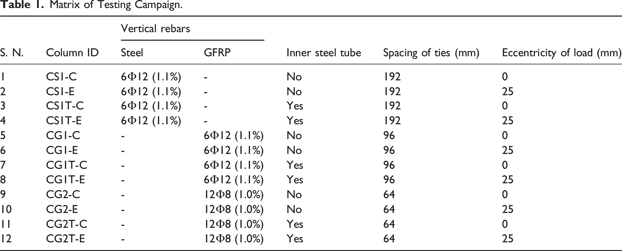
In the specimen identification code, the initial letter “C” denotes column, the subsequent letter signifies the material for vertical reinforcement (“G” for GFRP and “S” for steel), the third letter stands for the diameter of bar (using “1” for ϕ12 mm and “2” for ϕ8 mm), and the subsequent letter “T” indicates the presence of a steel tube as interior reinforcement (absent when no tube is utilized, and denoted as “T” for steel tube existence). The final letter following the hyphen indicates the loading condition (“C” means concentric and “E” means eccentric). Specimens having steel bars were employed as a benchmark for performance comparison with columns containing GFRP rebars. For eccentric loading scenarios, the eccentricity was consistently set at 25 mm. The adopted eccentricity was the maximum feasible for conducting the tests without compromising stability. It is also worth noting that this adopted eccentricity (10% of the column depth) lies within the practical limits for exterior columns in multistory buildings under gravity loading. A larger eccentricity would have necessitated the inclusion of a column head, which was not incorporated in this study. The addition of a column head (e.g., Lin et al., 2020), could have facilitated greater eccentricity, which is suggested for future studies.
For columns having vertical steel rebars, the tie spacing was 192 mm, adhering to the guidelines of the ACI 318 code (2019). The effect of tie spacing on the behavior of GFRP reinforced column was examined in a previous study by the authors (Abbas et al., 2023a). In this study, the tie spacing for the longitudinal GFRP bars was varied from 6 to 12 times the diameter of longitudinal bars. A tie spacing of 8 times the diameter of longitudinal bars was reported to be optimal, as reducing the tie spacing further did not result in any substantial increase in the ultimate load. Additionally, the post-peak behavior of columns remained sufficiently robust at this spacing. Thus, the tie spacing for columns having GFRP rebars was set at 8 times the diameter of the vertical rebar of the column (denoted as “d b ”). Consequently, in columns containing GFRP bars, the stirrup pitch was adjusted to 96 mm for ϕ12 mm bars and 64 mm for ϕ8 mm bars. These specified tie intervals were applied to roughly half of the column height. In the remaining upper and lower zones, which constituted nearly 25% of the specimen height, the tie spacing was set at 50 mm.
For all column specimens, ϕ8 mm steel rebars were employed as ties. However, in columns having vertical steel rebars, the ends of the ties were bent at a 45-degree angle, while in columns having vertical GFRP rebars, the tie ends were bent at a 90-degree angle to simulate the FRP ties in practical scenarios. Figure 1 demonstrate the sizes and details of the reinforcement of columns with a steel tube. Columns without steel tube were identical to those shown in Figure 1, except for the absence of the steel tube. To monitor strain levels, strain gauges were utilized. These gauges were strategically placed on longitudinal and transverse rebars, as well as on the steel tube (if present), situated close to the specimen’s mid-height. Dimensions and reinforcement details of columns having 70 mm square steel tube: (a) CS1T; (b) CG1T; and (c) CG2T (Unit: mm).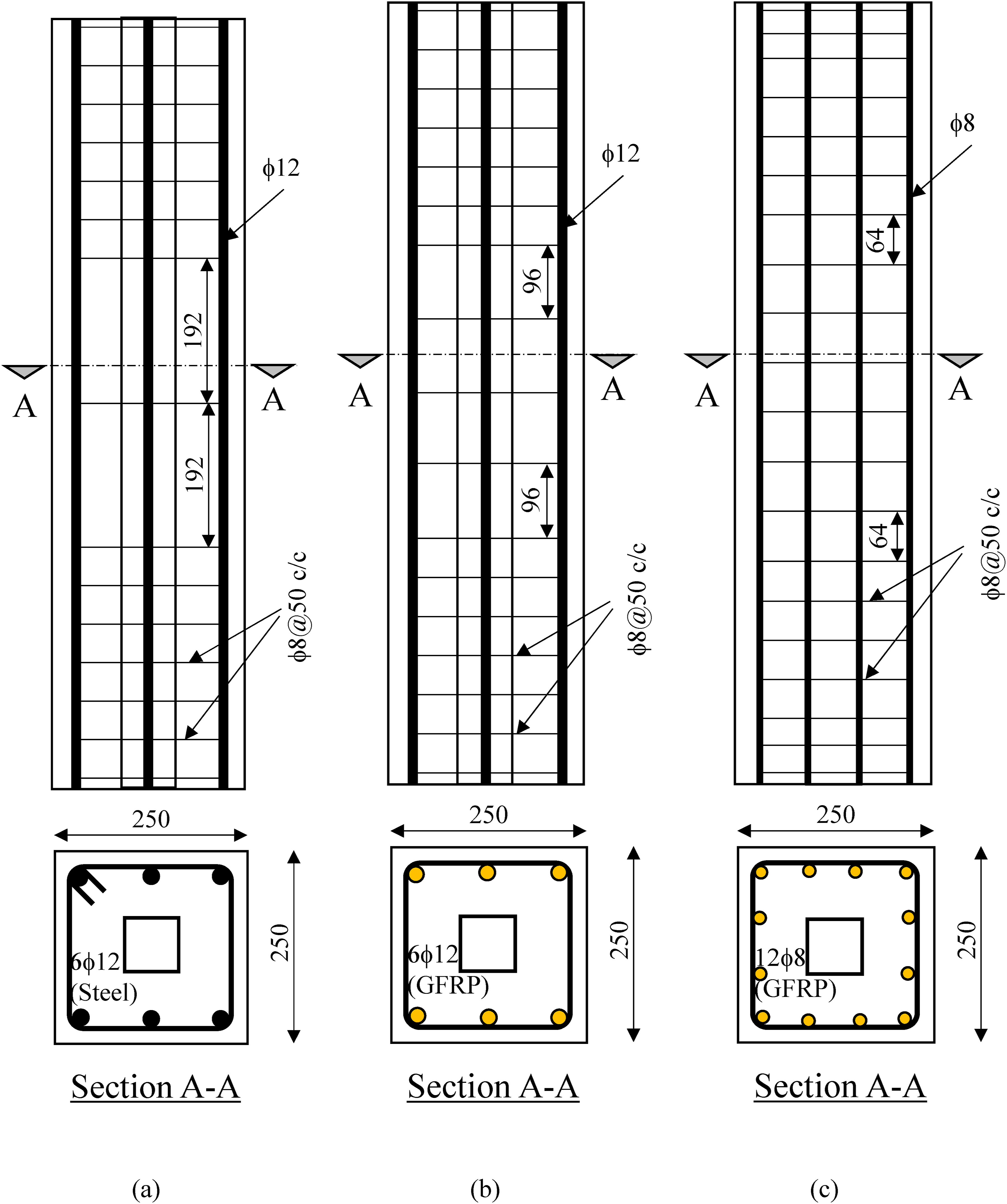
Figure 2 illustrates the positioning of reinforcement cages within wooden formwork subsequent to the installation of strain gauges. The specimens were fabricated utilizing ready-mix concrete sourced from a local provider. To ensure uniformity in the concrete quality, all column specimens were cast concurrently. Following casting, the specimens were enveloped with damp gunny bags, and a thrice-daily regimen of water sprinkling was implemented to maintain the bags’ moisture. Following a curing period of 28 days, the columns were removed from the molds and subjected to testing. Columns having steel tube ready for casting: (a) reinforced with steel rebars; and (b) reinforced with 12-mm diameter GFRP rebars.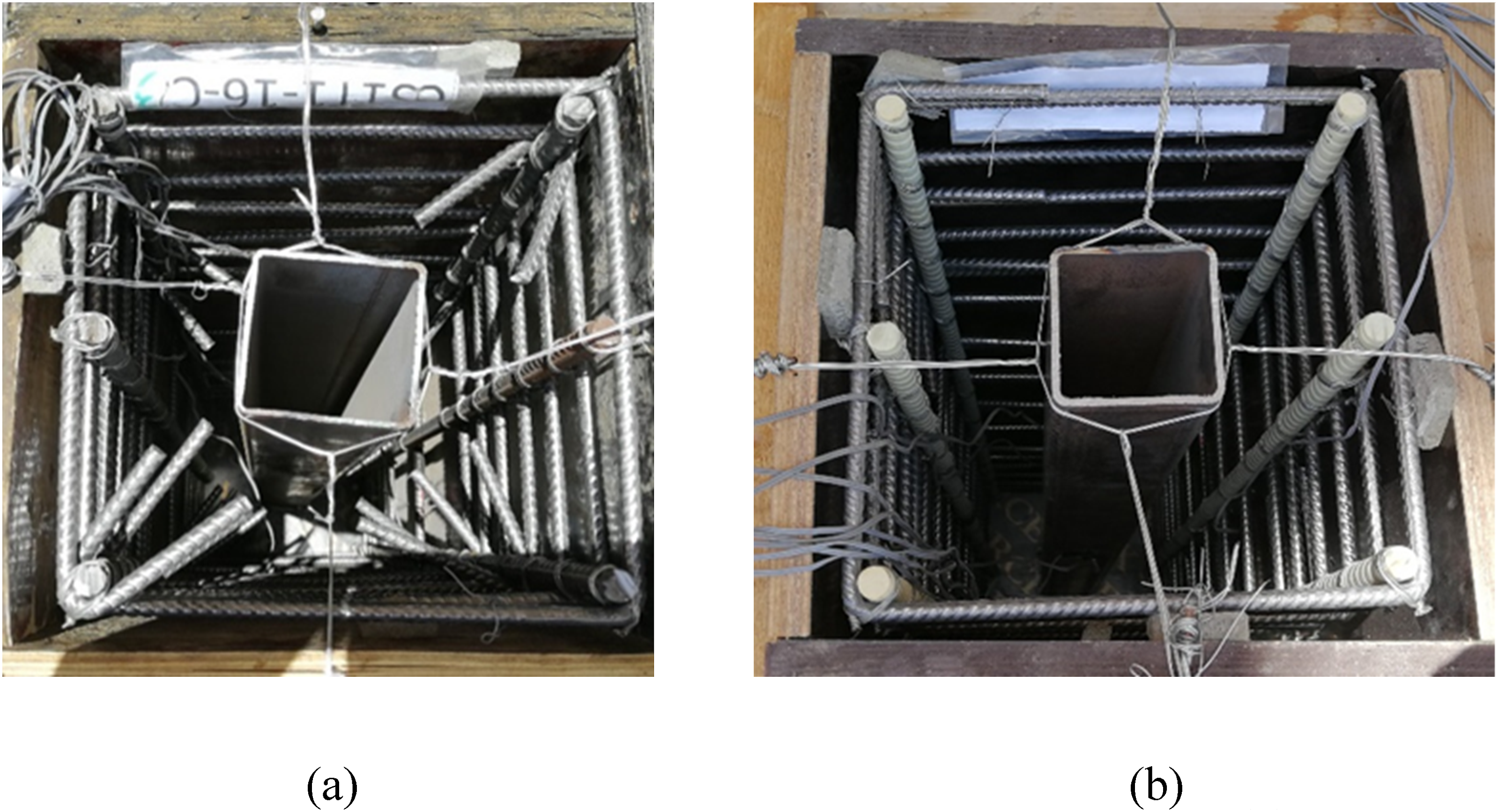
Setup for column testing
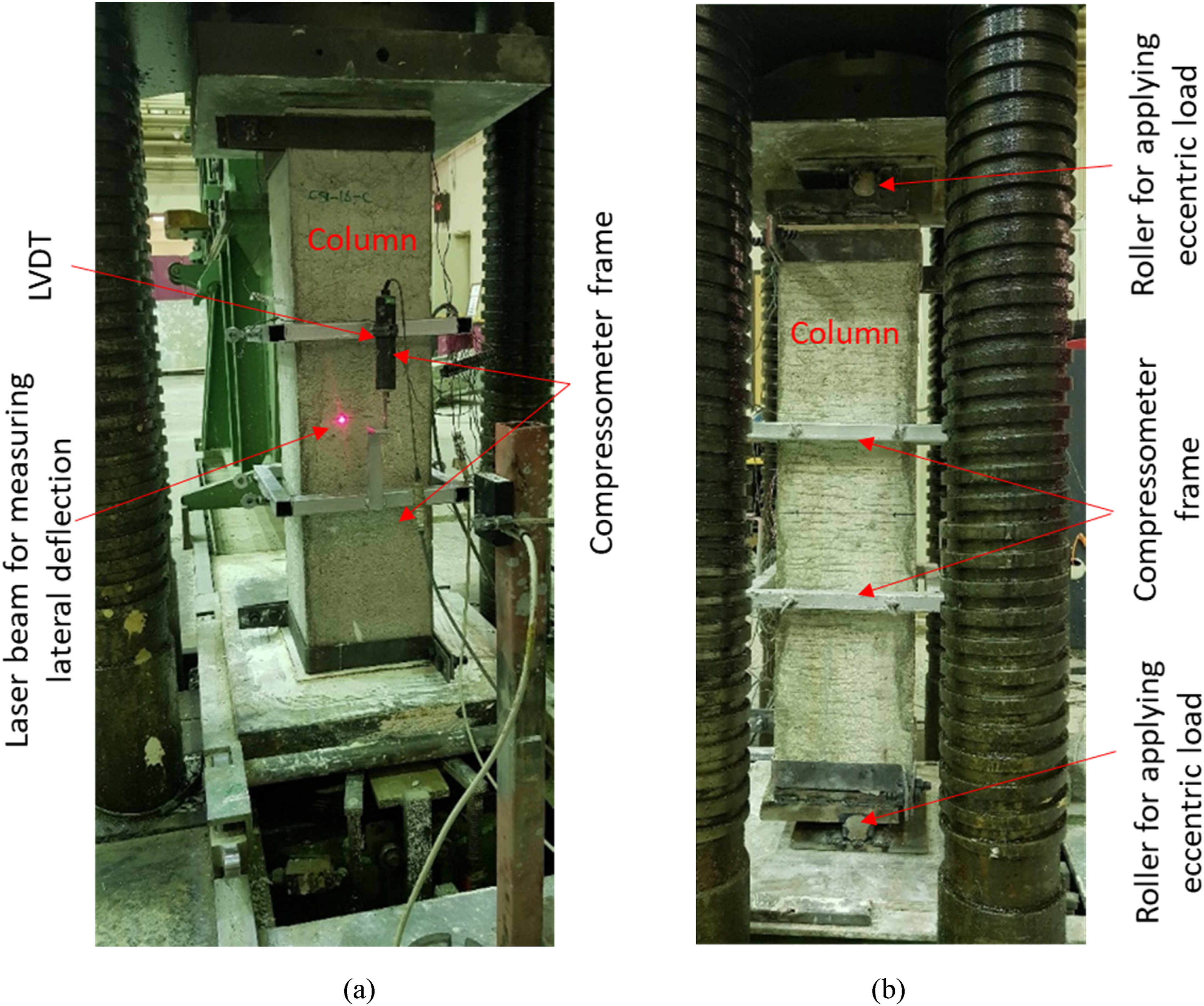
LVDTs were employed to instrument the column specimens, enabling the measurement of vertical compression. The transverse deflection at the column mid-height was measured using laser displacement sensor. Strain gauges were utilized to record strains in steel and GFRP rebars as well as in steel tubes (if existing). Figure 3 shows the layout of strain gauges in column cross-sections at the mid-height of columns. The testing of columns involved subjecting them to displacement-controlled loading, with compression increasing monotonically at a rate of 0.5 mm/min until reaching failure. Figure 4 depicts the test setup for testing columns under concentric and eccentric loads. The test setup is similar to some of the past studies (e.g., Al-Salloum et al., 2018; Lin et al., 2020). Location of strain gauges in column cross-sections at mid-height of columns for: (a) concentrically loaded columns, (b) eccentrically loaded columns (Note: All dimensions are in mm; Red circles and blue rectangles represent the vertical and horizontal strain gauges, respectively). Test setup for testing columns under: (a) concentric; and (b) eccentric loads.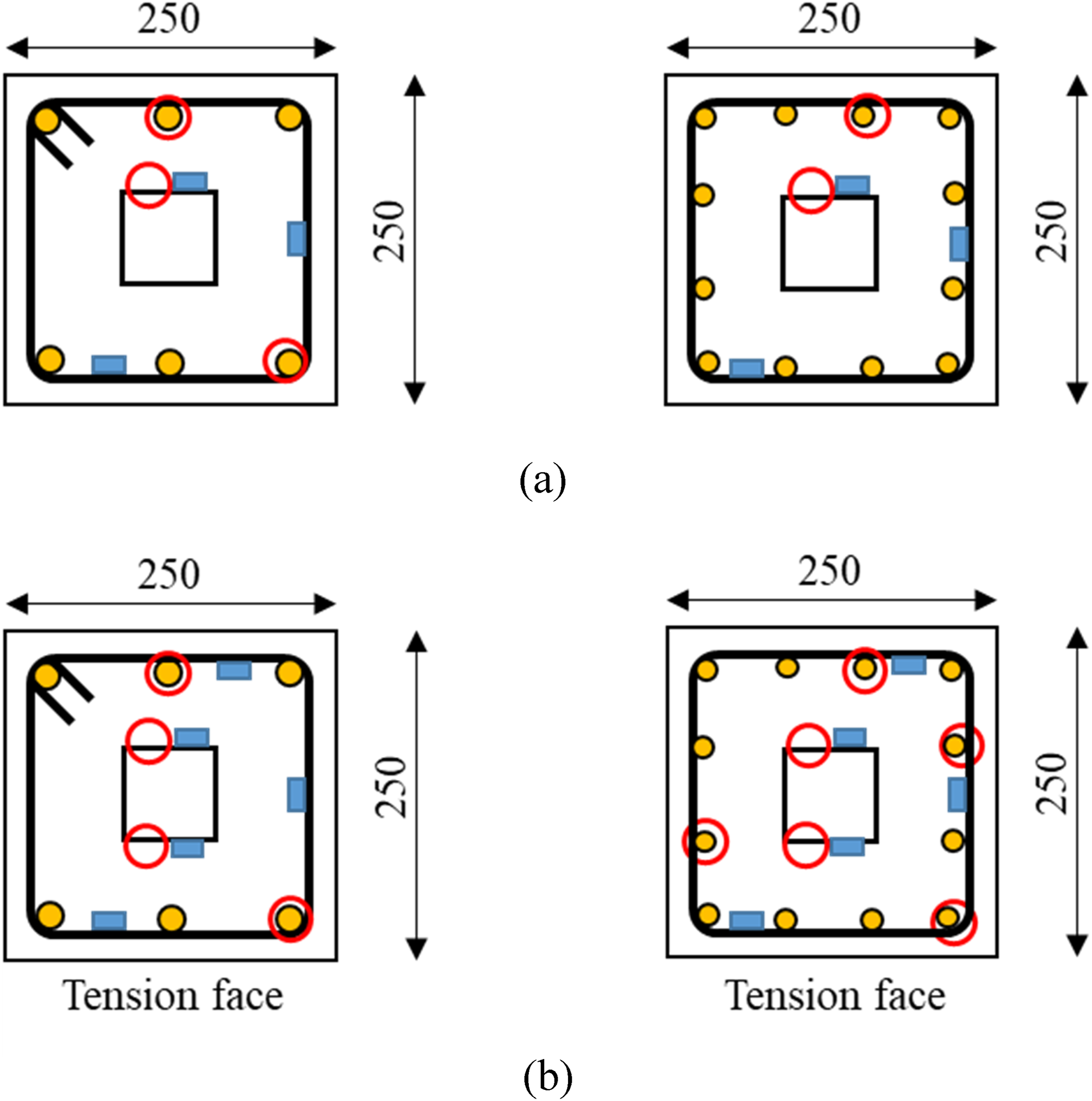
Discussion of test findings
Failure modes and load-displacement response
Figure 5 illustrates the modes of failure of the columns reinforced with steel rebars and GFRP bars and tested in compression as well as eccentric compression. Failure of columns reinforced with: (a) steel rebars; (b) GFRP rebars tested under concentric compression; and (c) GFRP rebars tested under eccentric compression.
Specimens having vertical steel bars
Figure 6 displays the load versus displacement behaviors of the specimens, all of which had vertical steel bars (CS1-C, CS1-E, CS1T-C, and CS1T-E). In the case of columns subjected to eccentric loading, there was an initial presence of compression on both the N-face and S-face (with the N-face being nearer to the load). As the load increased, the strain on the S-face transitioned into tensile. Load-axial displacement variation for columns reinforced with steel rebars: (a) CS1-C; (b) CS1T-C; (c) CS1-E; and (d) CS1T-E.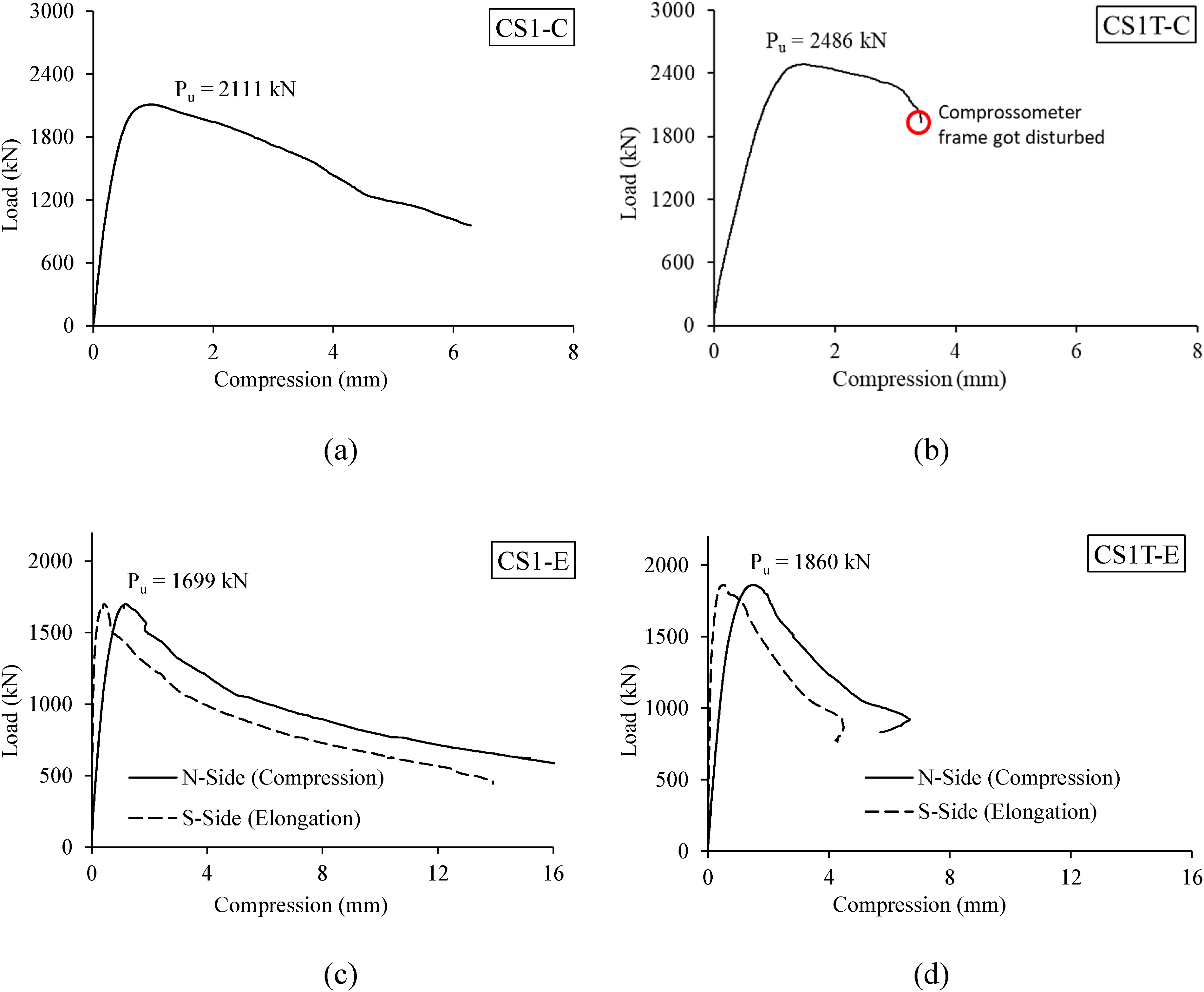
Incorporating a steel tube into the reinforced concrete column increased the maximum load capacity from 2111 kN to 2486 kN, representing a rise of 17.8%. However, the column with the steel tube (CS1T-C) exhibits a decrease in the post-peak segment of the load-displacement graph (see Figure 6(b)), which is due to the disturbance of the compressometer frame during testing. Consequently, the column compression could not be subsequently recorded. In comparison to loading that is concentric, subjecting the column to eccentric loading (with an eccentricity of 25 mm) leads to a decrease in the maximum load. Specifically, the maximum load diminishes from 2486 to 1860 kN for columns with a steel tube, and from 2111 to 1699 kN for columns without a steel tube. The failure mechanism for all columns commences with the crushing of concrete and the cover spalling around the column mid-height zone. This process causes the separation of concrete from the steel bars, subsequently leading to the buckling of the rebars (as depicted in Figure 5).
Columns having GFRP rebars
Figure 7 illustrate the load-displacement plots of columns that were reinforced using GFRP rebars and subjected to concentric compression testing (CG1-C, CG1T-C, CG2-C, and CG2T-C). The columns had vertical rebars with two distinct arrangements and diameters. The load versus displacement graphs of specimens tested under eccentric load (CG1-E, CG1T-E, CG2-E, and CG2T-E) are presented in Figure 8. Load-axial displacement variation for columns reinforced with GFRP rebars tested under concentric compression: (a) CG1-C; (b) CG1T-C; (c) CG2-C; and (d) CG2T-C. Load-axial displacement variation for columns reinforced with GFRP rebars tested under eccentric compression: (a) CG1-E; (b) CG1T-E; (c) CG2-E; and (d) CG2T-E.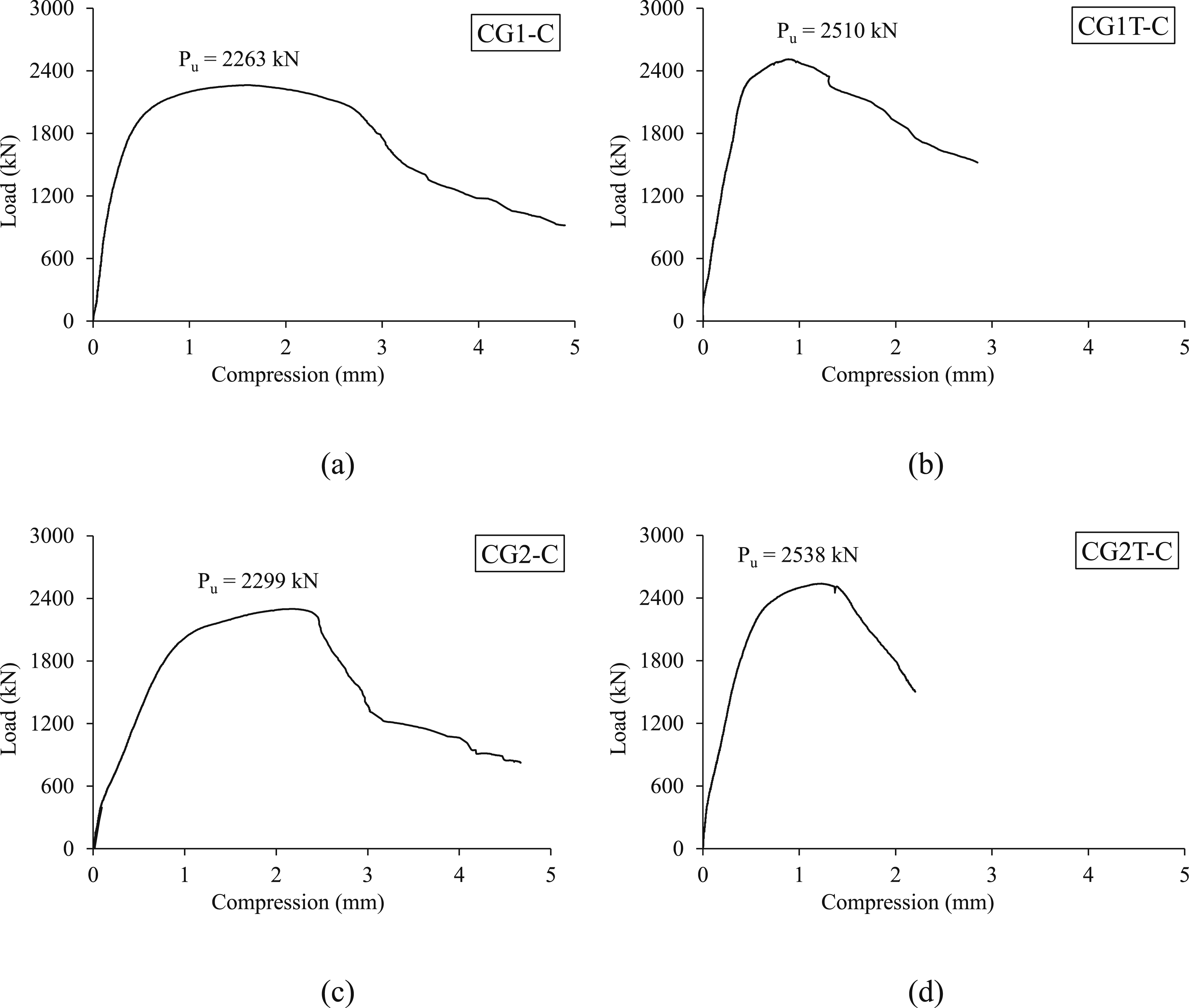
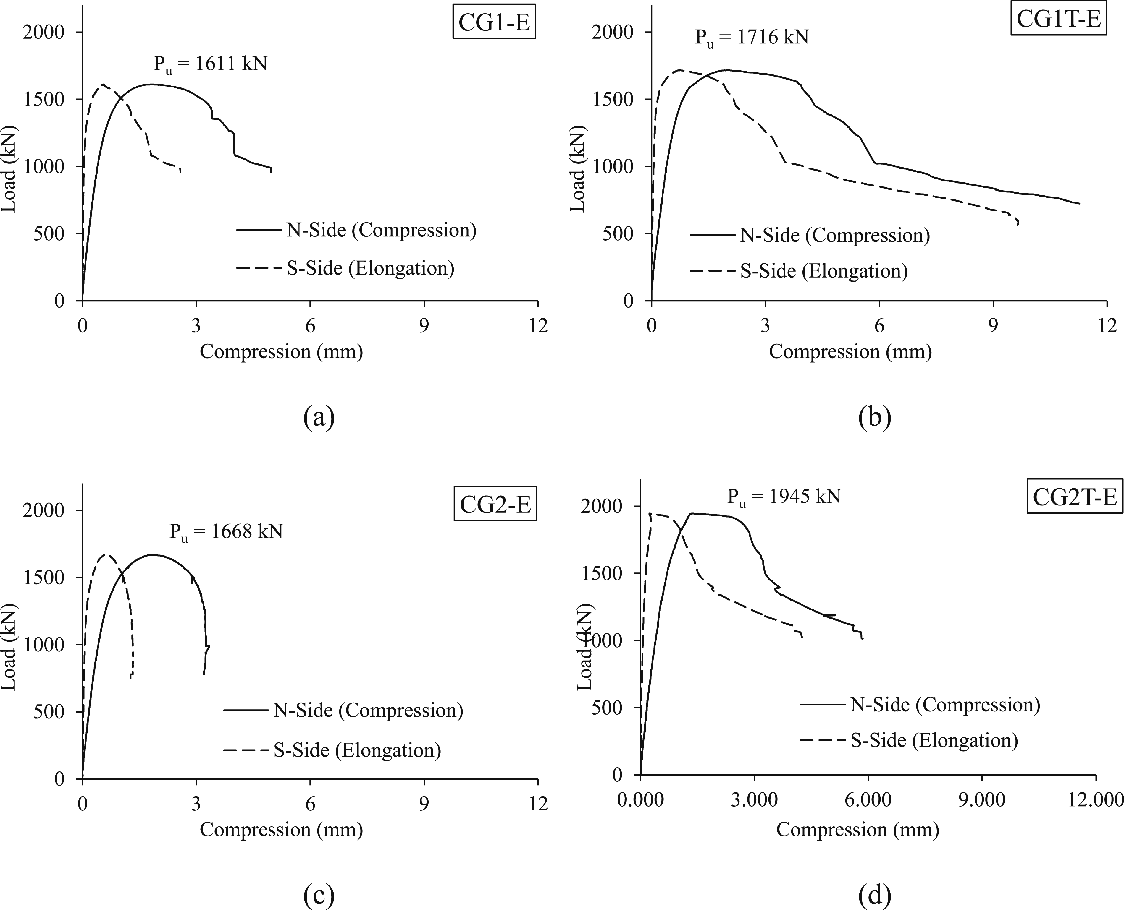
The load-displacement curves for specimens tested in the event of concentric and eccentric load exhibit a satisfactory post-peak segment. Nonetheless, it is noticeable that the post-peak phase of the plots for ϕ8 mm GFRP rebars is comparatively shorter when compared to columns reinforced with ϕ12 mm GFRP rebars. This observation holds true for specimens tested under either concentric or eccentric loading conditions, invloving those without a tube and those featuring a steel tube. This discrepancy arises due to variations in rebar arrangement between the two diameters. In the case of ϕ8 mm GFRP rebars, four rebars are positioned closer to the neutral axis, which leads to a relatively diminished contribution in withstanding bending moments. This pattern is also evident in subsequent P-M interaction analysis. All columns experienced initiation of failure through concrete damage and cover spalling, occurring close to the mid-height region. The crushing of GFRP bars is also observable in the specimens.
The concrete surrounding the steel tube was removed to expose the tube, as shown in Figure 9. During this process, the steel tube remained intact without any deformation or damage. For evaluating the status of concrete filling inside the steel tube, a section of the tube was cut open after removing the concrete. This revealed that the tube was adequately filled, as depicted in Figure 9. The columns failure was triggered by the damage of concrete and the spalling of the concrete cover close to the middle of the column on its compressed side. Ultimately, the columns failed when the GFRP rebars on the compression face were crushed. Notably, the cracking of the concrete was confined to the cover surrounding the longitudinal rebars and did not extend to the inner steel tube. As a result, the likelihood of corrosion in the steel tube is minimal, as it remains shielded from the external environment, even during the post-peak damage phase. Steel tube exposed after removing concrete surrounding the tube in the middle portion of a tested column and after cutting open the steel tube: (a, b) CG1T-C; and (c, d) CG2T-C.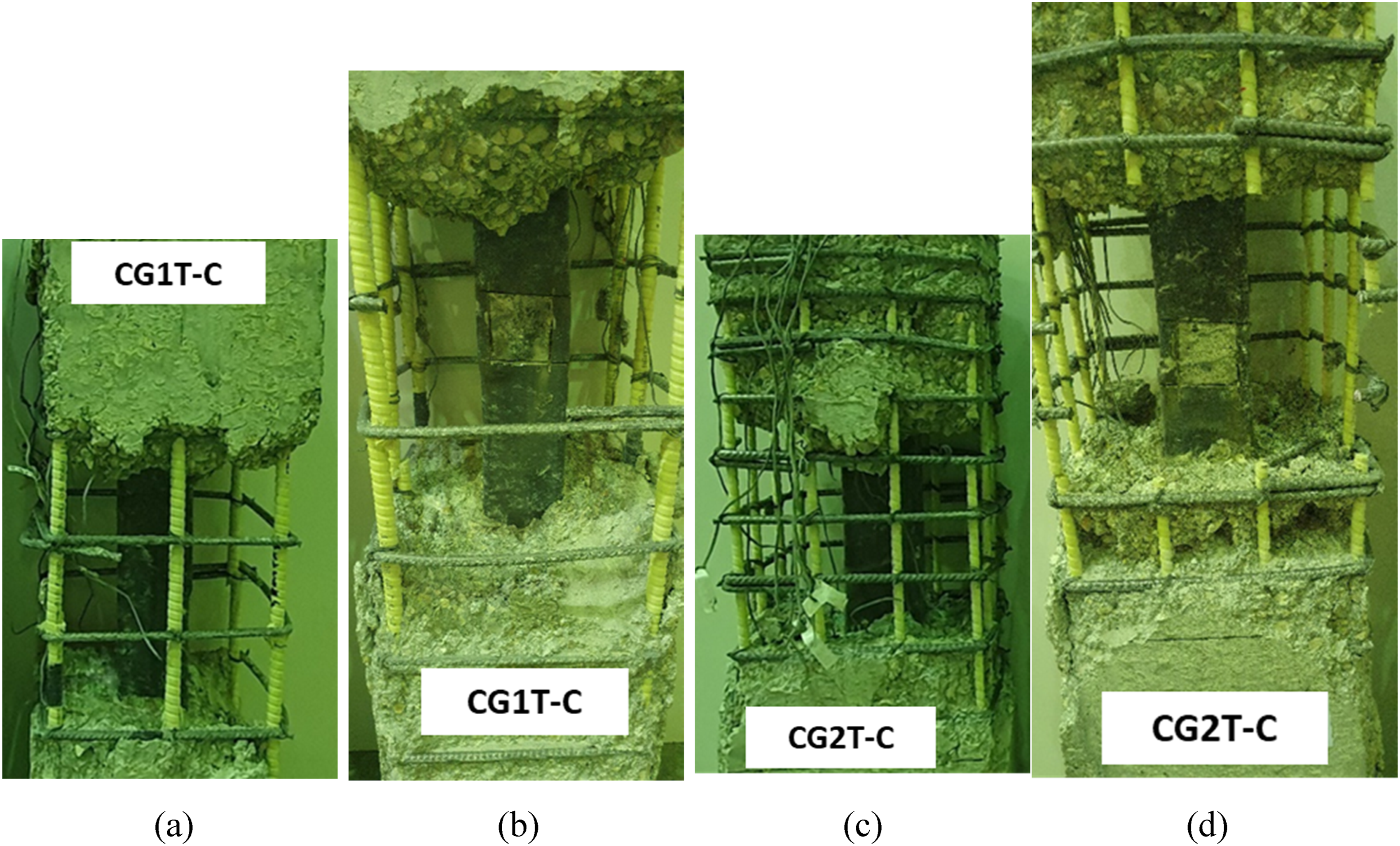
It can be noted from the failure modes that when the vertical rebars buckle, they exert force on the column ties. The ties, with their straight ends, were pulled out from the crushed section of the column (see Figure 5). This is owing to the fact that the tie ends had a 90-degree bend. It is important to highlight that the straight configuration of the tie ends was maintained to replicate the conditions of GFRP stirrups. To prevent the pulling out of column ties, it is advisable to determine the length of the end of ties accounting for the concrete cover. Investigating this aspect further will necessitate future research endeavors. However, when using FRP ties, the ends can be bonded to rigid end composite anchors for better anchorage with concrete (e.g. Maranan et al., 2015; Shakiba et al., 2022).
Effect of the diameter of vertical rebars
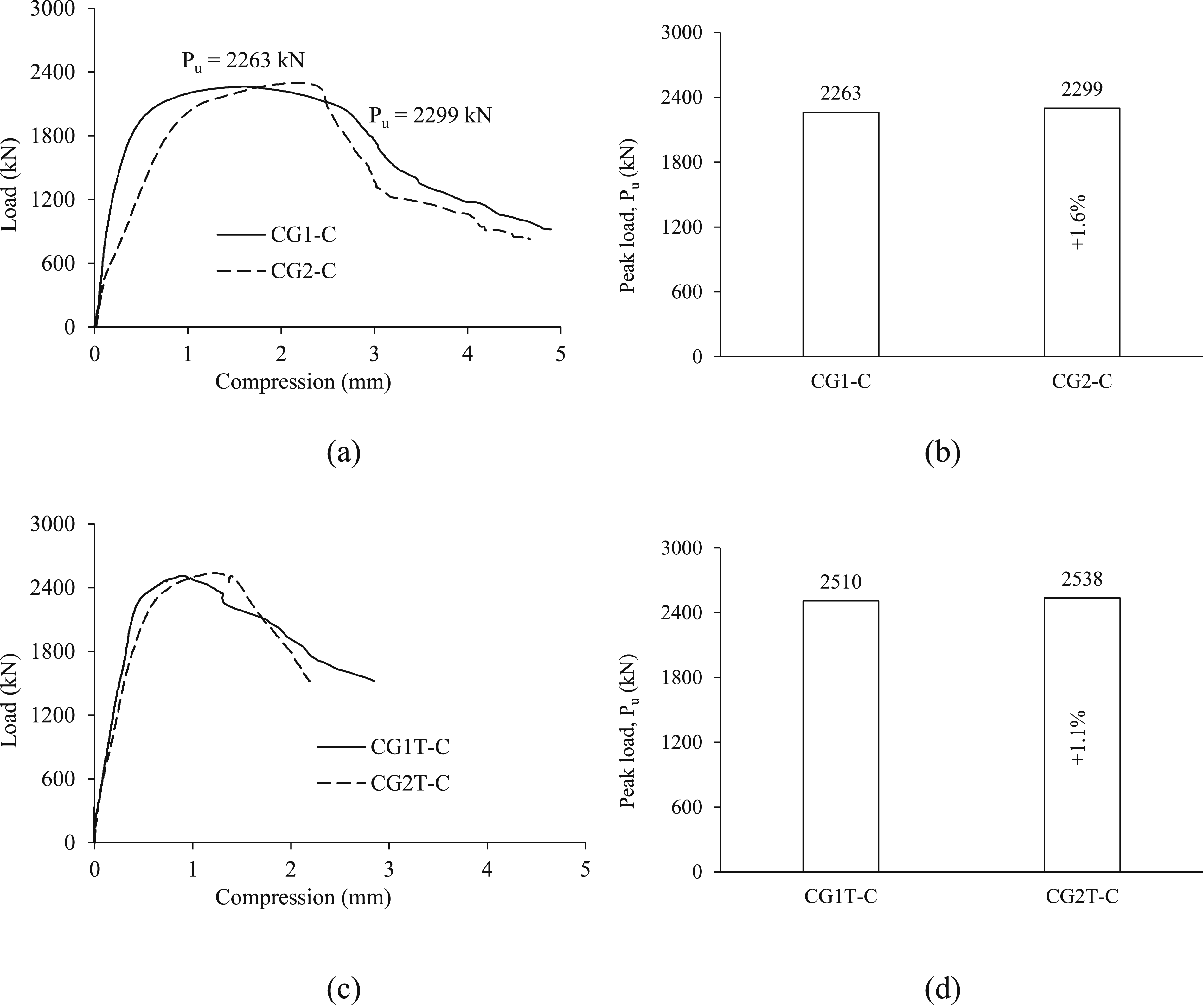
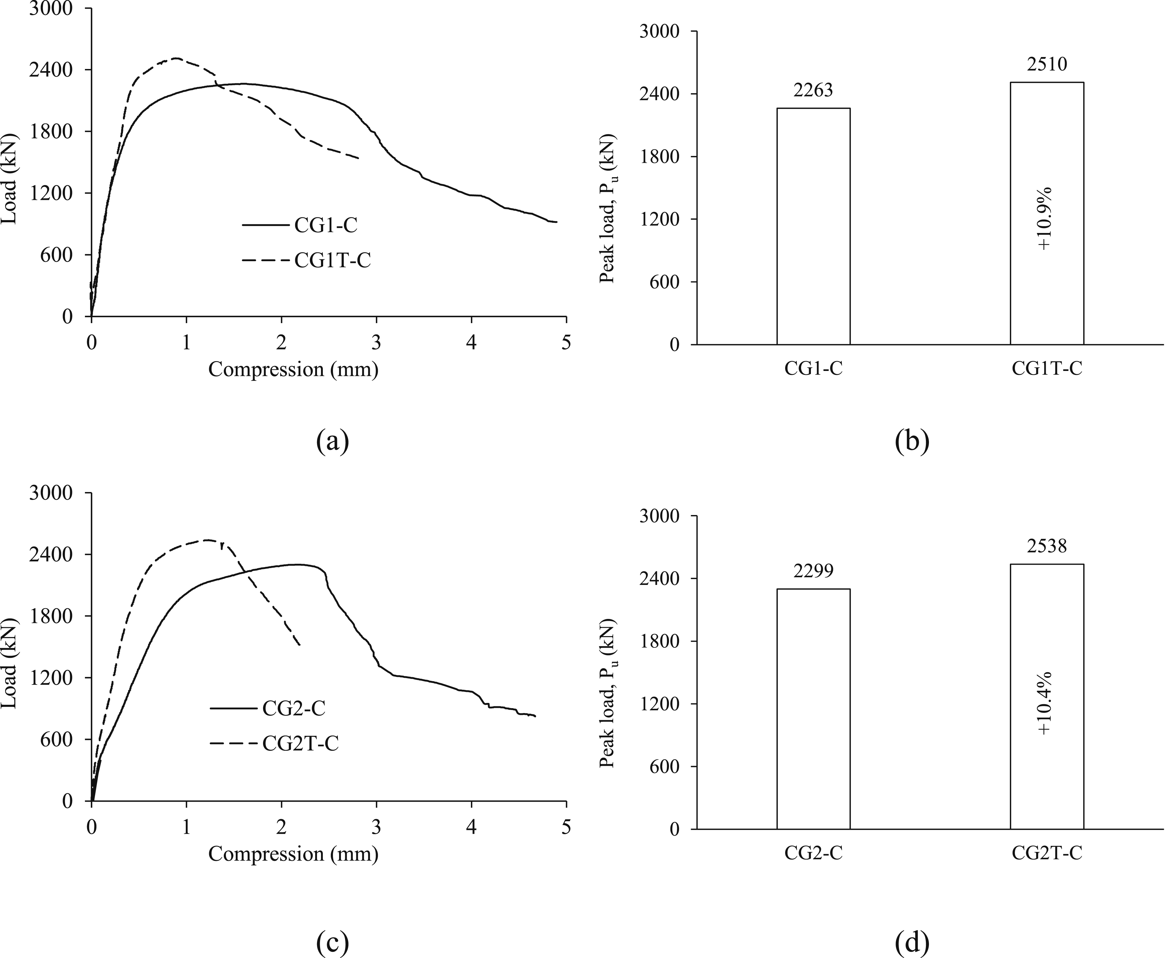
The load against axial deformation behavior of specimens of the two GFRP bar diameters is compared in Figure 10. These columns were tested under concentric load. The graph also shows a comparison of the peak load extracted from these plots. The insights derived from these plots include: (i) Irrespective of the columns having or not having steel tube, the maximum load and the axial deformation response of the specimens having ϕ8 and ϕ12 mm GFRP bars is almost the same. For columns without steel tube, the maximum load of the specimen containing 8-mm diameter rebars is 2299 kN, which is only 1.6% higher than that of the column having 12-mm diameter rebars. A similar trend is observed for columns having a steel tube, as the peak load of the column having 8-mm diameter rebars is 2538 kN, which is only 1.1% higher than that of the column having 12-mm diameter rebars. Although the area of 12ϕ8 rebars is 11% less than the area of 6ϕ12 rebars, the strength of ϕ8 mm rebars is 32.4% higher than that of ϕ12 mm diameter GFRP rebars. It is due to these reasons that the disparity in peak load between the columns of the two bar diameters is minimal. (ii) The commencement of column failure for both bar diameters was instigated by concrete damage and cover spalling. Nevertheless, the final column failure was owing to the crushing of the GFRP rebars. Consequently, the failure mode remains unaffected by the rebar diameter. Effect of GFRP rebar diameter in columns on: (a, b) load-compression behavior and peak load of columns CG1-C and CG2-C; and (c, d) load-compression behavior and peak load of columns CG1T-C and CG2T-C.
Effect of using a steel tube as internal reinforcement
Columns having steel rebars
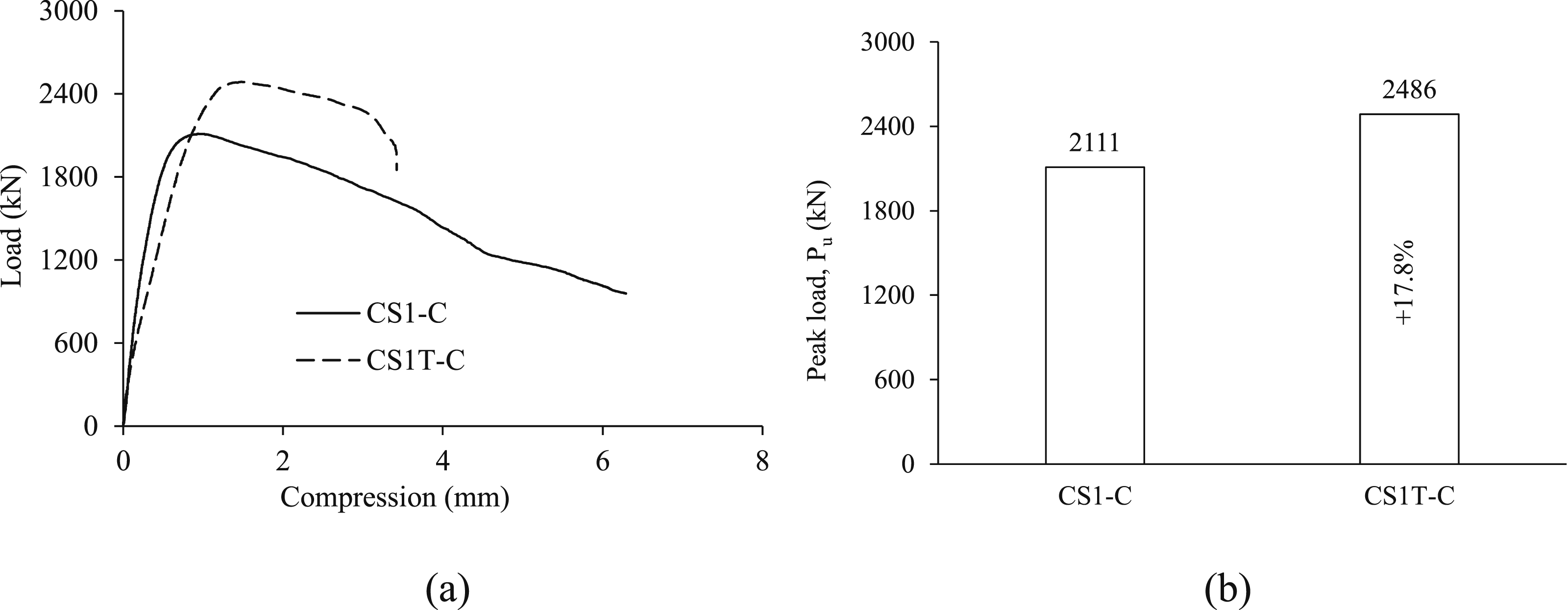
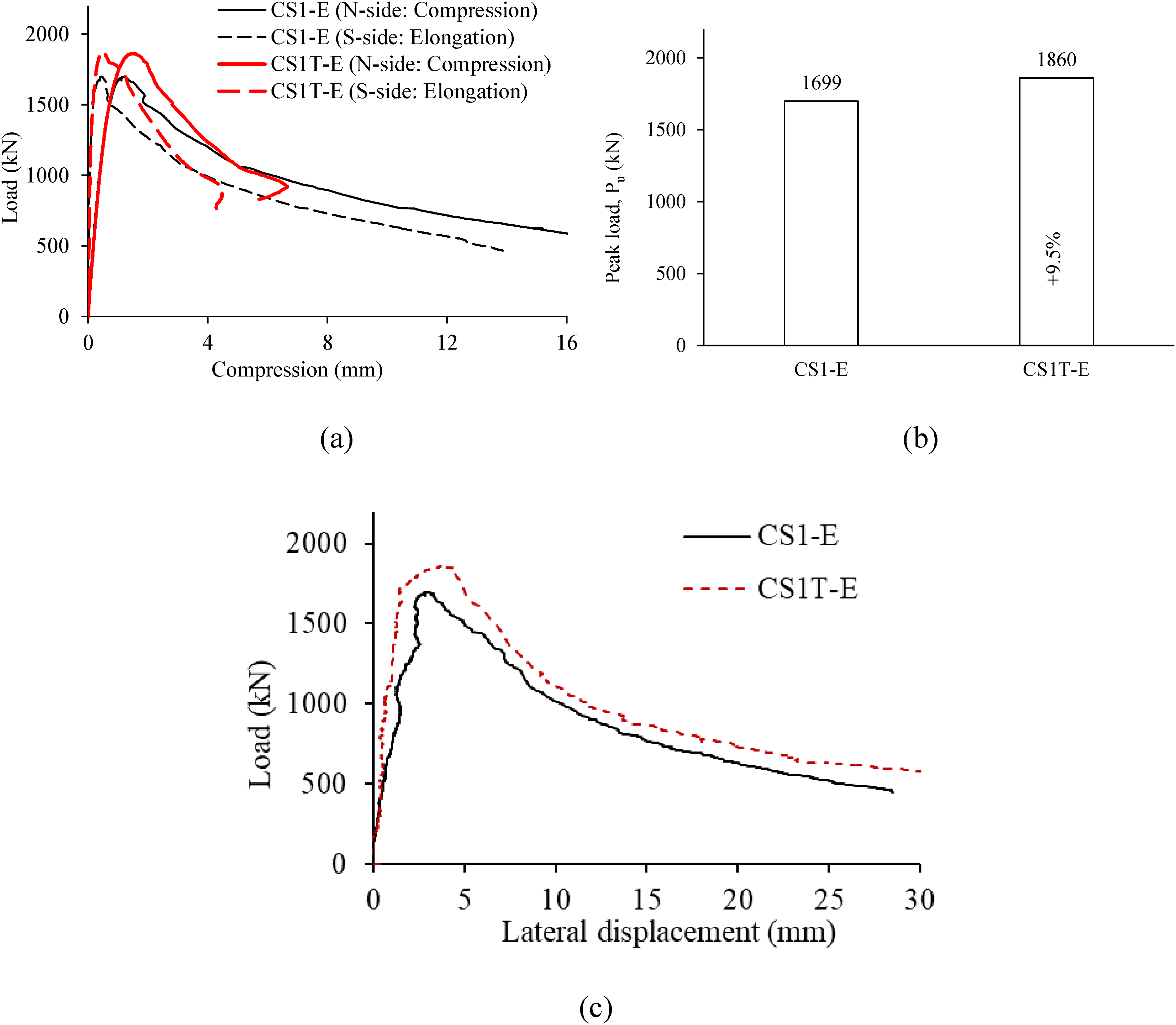
The load against deformation graphs of the steel-reinforced specimens subjected to concentric compression (i.e., CS1-C and CS1T-C) are compared in Figure 11(a). The maximum load attained from the load-displacement graphs is displayed in Figure 11(b). The load versus deformation response and peak load of eccentrically loaded columns CS1-E and CS1T-E is presented in Figure 12(a), (b). The load versus lateral deflection of column at mid-height obtained from the laser displacement sensor are plotted in Figure 12(c). The insights derived from these plots include: (i) The addition of a steel tube as interior reinforcement in concentrically loaded specimens caused an 18% increase in the maximum load as it increased from 2111 to 2486 kN. The increase in load (376 kN) is 85% higher than the yield strength of additional reinforcement, i.e., steel tube (203 kN), which is due to the confinement of concrete inside the tube. It is worth mentioning here that the confinement offered by the steel tube is more than that offered by the ties. (ii) The addition of a steel tube as internal reinforcement in eccentrically loaded columns triggered a 9.5% enhancement in the maximum load as it increased from 1699 to 1860 kN. The reasons for the lower increase in columns subjected to eccentric compression as compared to those subjected to concentric compression can be elucidated in the following manner. Firstly, the effect of confinement of concrete by the steel tube has a very small effect in bending as compared to axial compression. Secondly, the area of steel tube being closer to the centroid and hence the neutral axis of the section has a smaller contribution in resisting bending as compared to the axial compression. (iii) For columns subjected to either concentric or eccentric compression, the provision of a steel tube reduced the post-peak segment of the load-displacement curves. This occurs owing to the reinforcement offered by the steel tube positioned near the specimen’s longitudinal axis. (iv) As expected, the failure pattern of both the specimens is by concrete damage and consequent buckling of vertical steel rebars and steel tube, if present. Effect of adding steel tube in concentrically loaded RC columns on: (a) load-compression behavior of columns; and (b) peak load of columns. Effect of adding steel tube in eccentrically loaded RC columns on: (a) load-compression behavior of columns; (b) peak load of columns; and (c) load-lateral displacement behavior of columns.
Columns having GFRP rebars
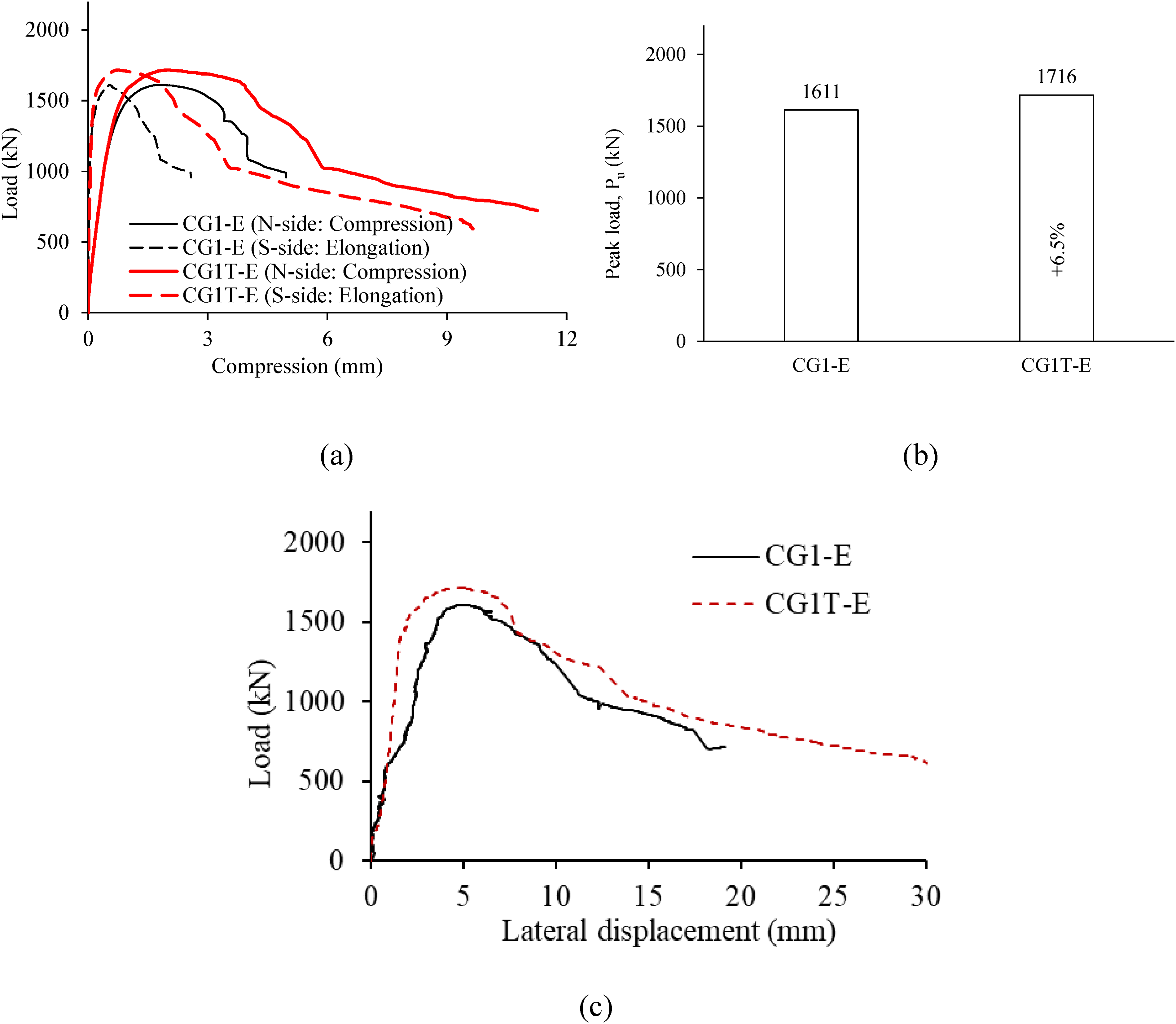
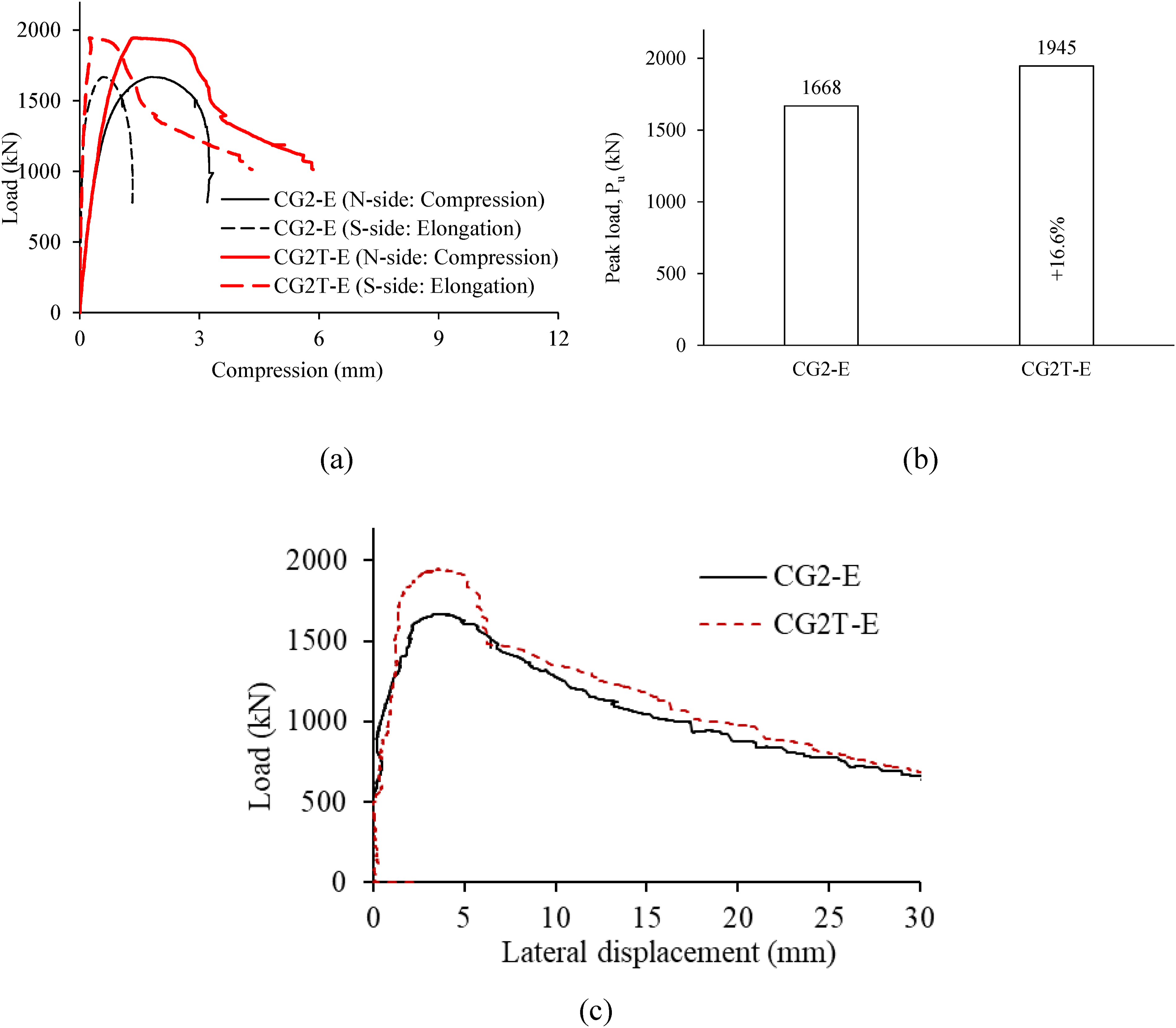
Figure 13(a) presents a comparison of the load against deformation graphs and the maximum load of concentrically loaded columns. The obtained peak load is further presented in Figure 13(b). The load versus deformation graphs and the maximum load of eccentrically loaded specimens CG1-E and CG2-E are depicted in Figure 14(a), (b) and Figure 15(a), (b), respectively. The load versus lateral deflection of columns CG1-E and CG2-E at mid-height obtained from the laser displacement sensor are plotted in Figure 14(c) and Figure 15(c), respectively. The insights derived from Figures 13, 14, 15 are as follows: (i) The addition of a steel tube as internal reinforcement in RC columns having 6ϕ12 mm GFRP rebars and subjected to concentric compression increased the maximum load from 2263 kN to 2510 kN (increase = 10.9%). The increase in load (247 kN) is 22% higher than the increase caused by additional reinforcement (203 kN). The increase in maximum load of specimens having 12ϕ8 mm GFRP rebars is also almost the same (10.4%), as the peak load increased from 2299 kN to 2538 kN. The increase in load (239 kN) is 18% higher than the increase caused by additional reinforcement (203 kN). This increase can be ascribed to the confinement of concrete within the tube. (ii) For the eccentrically loaded column reinforced with 6ϕ12 mm GFRP rebars, the addition of a steel tube caused a 6.5% enhancement in maximum load as the maximum load increased from 1611 kN to 1716 kN. As explained above for specimens having steel rebars, the lower increase in eccentrically loaded columns as compared to the columns subjected to concentric compression is owing to: (i) insignificant effect of the confinement of concrete by steel tube in bending as compared to the axial compression, and (ii) the smaller contribution of the tube in resisting the bending as compared to the axial compression as the tube area is close to the neutral axis of the column section. (iii) For the eccentrically loaded column having 12ϕ8 mm GFRP rebars, the addition of a steel tube caused a 16.6% increase in peak load as the maximum load increased from 1668 kN to 1945 kN. The higher enhancement in maximum load in contrast to to the column having 6ϕ12 mm GFRP rebars is due to the difference in the layout of longitudinal rebars. The column having 12Ф8 rebars provided better confinement to the concrete outside the steel tube on all four sides. The smaller post-peak segment of the load versus displacement curve as compared to column CG1T-E is owing to the higher enhancement in the load-bearing resistance. (iv) For the specimens of both rebar diameters, the addition of a steel tube increased the post-peak segment of the load versus deformation plots of eccentrically loaded columns, thereby enhancing the ductility. However, for columns tested under concentric compression, the addition of a steel tube caused almost no change in the post-peak segment of the load versus deformation plots. Despite the reinforcement provided by the steel tube lying close to the column’s longitudinal axis, the addition of the steel tube introduced ductility in columns tested under eccentric loads. (v) The initiation of column failure occurred due to concrete crushing and spalling of the concrete cover close to the mid-height of the compression face. Nevertheless, the ultimate column failure resulted from the crushing of GFRP rebars on the compression face. Effect of adding steel tube in GFRP-reinforced columns on: (a, b) load-compression behavior and peak load of columns CG1-C; and (c, d) load-compression behavior and peak load of columns CG2-C. Effect of adding steel tube in CG1-E columns on: (a) load-compression behavior of columns; (b) peak load of column; and (c) load-lateral displacement behavior of columns. Effect of adding steel tube in CG2-E columns on: (a) load-compression behavior of columns; (b) peak load of column; and (c) load-lateral displacement behavior of columns.
Assessment of ultimate load of test columns
The guidelines of the ACI 440.1R-15 (2015) suggest disregarding the utilization of GFRP bars in bearing compressive stresses within concrete elements. This decision stems from the minimal load-bearing compression capacity exhibited by GFRP rebars and the substantial variability noted in numerous prior studies (Afifi et al., 2013; De Luca et al., 2010; Mohamed et al., 2014; Tobbi et al., 2012). Consequently, the ACI 440 (2015) advises against the utilization of GFRP rebars in compression members. To ascertain the capability of GFRP rebars to withstand compressive loads, the test findings were compared with predictions that exclude the load-bearing contribution of GFRP rebars.
By disregarding the load carried by GFRP rebars in compression, the load-bearing resistance of specimens having a hybrid of steel and GFRP rebars and a steel tube can be calculated using: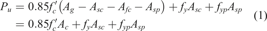
Another approach suggested in a past study (Hadhood et al., 2019) is to compute the load-bearing capacity of columns having GFRP rebars by accounting for the strength of GFRP bars the same as that of concrete, giving:

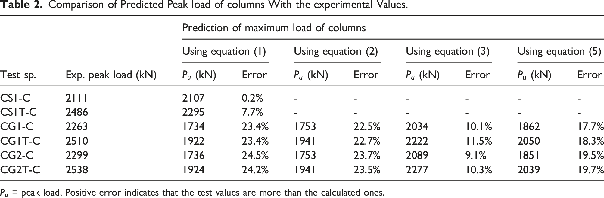
Comparison of Predicted Peak load of columns With the experimental Values.
An alternative method, later employed in other studies (Hadi et al., 2016; Tobbi et al., 2014), involved utilizing the linear-elastic theory of GFRP bars. In this case, they evaluated the load-bearing resistance of GFRP bars by considering the mean axial strain of these bars. This adjustment alters equation (3) to yield:
The method of integrating the compressive strength of GFRP rebars (while computing the maximum load) using their tensile (or compressive) strength, similar to how it is done with steel rebars, cannot be applied. This is because it would contradict the strain compatibility principle of the linear-elastic concept. Nonetheless, the methodology relying on strain proves to be more suitable.
The strain observed in GFRP bars at the point of maximum load ranges from 0.0030 to 0.0054, with an average value of 0.0037. Therefore, it is prudent to consider 
The load-bearing capacity of tested specimens predicted using equations (1), (2), (3), and (5) are compared with the values obtained experimentally in Table 2. The prediction errors are also reported in the table. The prediction for the steel-reinforced columns is good (slightly conservative), with the error in prediction being 0.7% and 7.7% for CS1-C and CS1T-C, respectively. However, the error in the prediction for GFRP-reinforced columns is more. Disregarding the compressive resistance of GFRP bars, the error in the prediction of peak load for specimens containing GFRP bars estimated using equation (2) varies from 23.4% to 24.5%. As expected, taking the resistance of GFRP bars equal to the strength of concrete caused only marginal change in the prediction using equation (3), with the prediction error varying from 22.5% to 23.7%. Nevertheless, the prediction improved using equation (5), with the error varying from 17.7% to 19.7%. The prediction using equation (3) is the best due to the higher level of stress considered for GFRP bars, i.e.,
Load against moment (P-M) behavior of columns
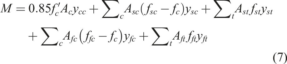
The subsequent analytical formulation was employed for generating the P-M interaction graphs of specimens having longitudinal FRP bars: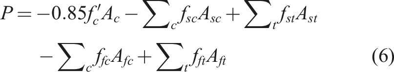
In the above equations, A
fc
and Asc denote, respectively, the area of FRP and steel rebars under compression, while Aft and Ast represent, in turn, the area of FRP and steel rebars under tension. Correspondingly, ffc and f
sc
, respectively, stand for the compressive stresses in FRP and steel rebars, whereas f
ft
and f
st
pertain to the tensile stresses in FRP and steel rebars, in turn. The concrete stress at the compression rebar’s location is denoted as f
c
, and y
cc
signifies the distance between the centroid of the concrete area (A
c
) and the centroid of the section. Additionally, y
fc
and y
sc
indicate, respectively, the distances of the compression FRP and steel bars from the centroid of the section, while y
ft
and y
st
represent, in turn, the distances of the tension FRP and steel bars from the centroid of the section. The notations
The load and moment of resistance (P and M) of the column section, which contains a mixture of steel and GFRP bars along with a steel tube, was obtained by analyzing the equations of equilibrium using the formulation provided above. The compression behavior of ϕ12 mm GFRP rebars was examined in a previous study by the authors (Abbas et al., 2023a). In this study, bar specimens were tested under compression with unsupported lengths of 4, 8, and 12 times the rebar diameter. The findings indicated that as the unsupported length decreased, the compressive strength of the GFRP bars increasingly approached their tensile strength. Consequently, for bonded GFRP rebars, the compressive strength was considered equivalent to the tensile strength, mirroring the behavior of steel rebars used in concrete columns. The compressive and tensile stresses in steel and FRP bars were calculated based on the strains developed in the rebars, which is explained in the authors’ previous study (Abbas et al., 2023a). The steel tube was discretized and each segment of the tube was considered as a steel rebar.
Figure 16(a) and 16(b) show the effect of adding a steel tube in steel (CS1) and GFRP (CG1 and CG2) reinforced columns. The addition of a steel tube in steel bar reinforced column caused an 8.9% increase in load resistance, but there was a 49% increase in the moment of resistance of the specimen (i.e., for P = 0), as the moment of resistance increased from 39.7 kN.m to 59.1 kN.m. The substitution of ϕ12 steel rebars in CS1 by ϕ12 GFRP rebars in CG1 caused a 40.4% caused enhancement in the moment of resistance of the column owing to the larger tensile resistance of GFRP rebars, as the moment of resistance increased from 39.7 kN.m to 55.8 kN.m. However, the addition of a steel tube in CG1T did not cause any increase in the moment of resistance because the addition of the steel tube increased the depth of the neutral axis from 35.5 mm to 48.9 mm. This caused considerable a reduction in the stress in GFRP rebars in tension, as it was reduced from 791.0 MPa to 523.6 MPa. Although the steel tube caused some increase in moment of resistance, but this was small as the tube was close to the neutral axis, and this increase was offset by the reduction in moment of resistance because of the reduction in the stress in the GFRP tension rebars. The impact of the addition of a steel tube in CG2T on the theoretical moment of resistance can also be explained in the same way. The inclusion of a steel tube in CG2T increased the depth of the neutral axis from 33.8 to 47.6 mm, which reduced the tensile stresses in bottom rebars from 857 to 553 MPa, due to which the increase in the moments of resistance was only 5.2%. Nevertheless, the theoretical increase in the load-bearing resistance of columns containing vertical GFRP bars owing to the addition of a steel tube is 10% for both rebar diameters. Effect of adding a steel tube on P-M interaction diagrams of columns having: (a) steel rebars (CS1 and CS1T); (b) GFRP rebars (CG1, CG1T, CG2, and CG2T) considering compression carried by rebars.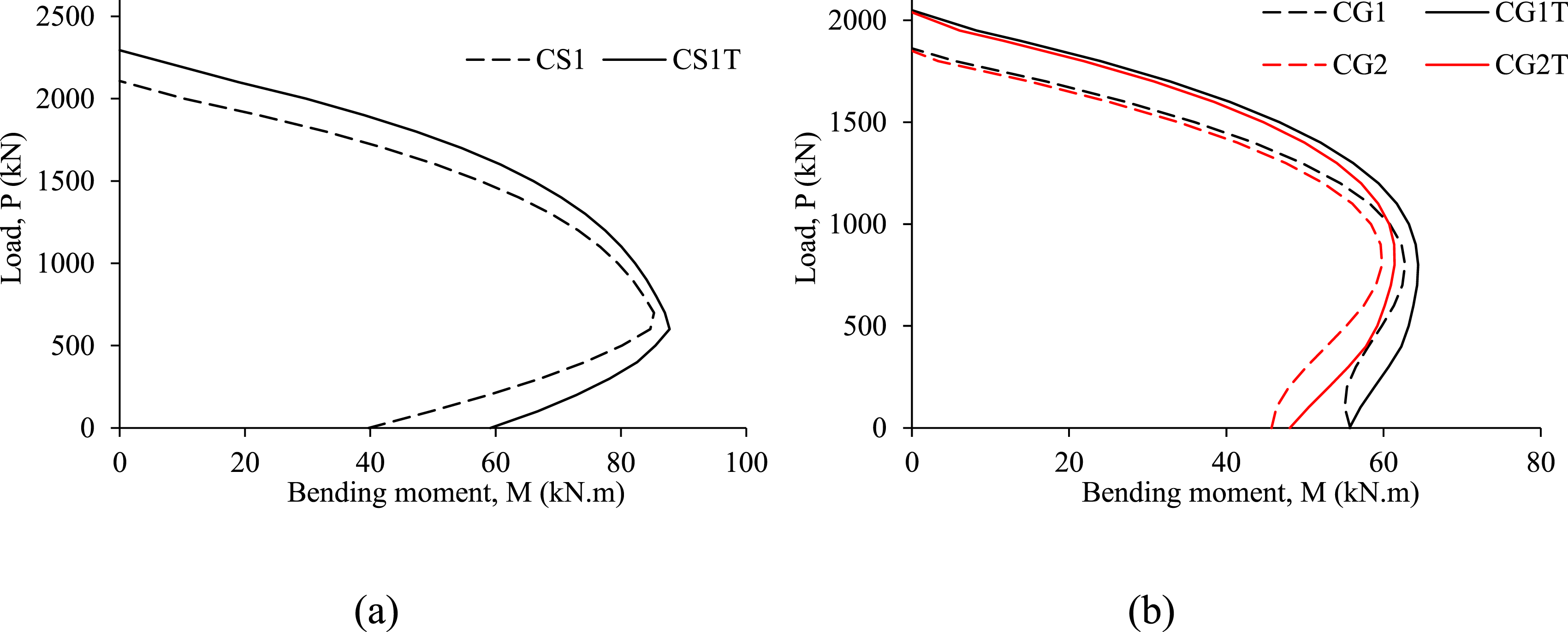
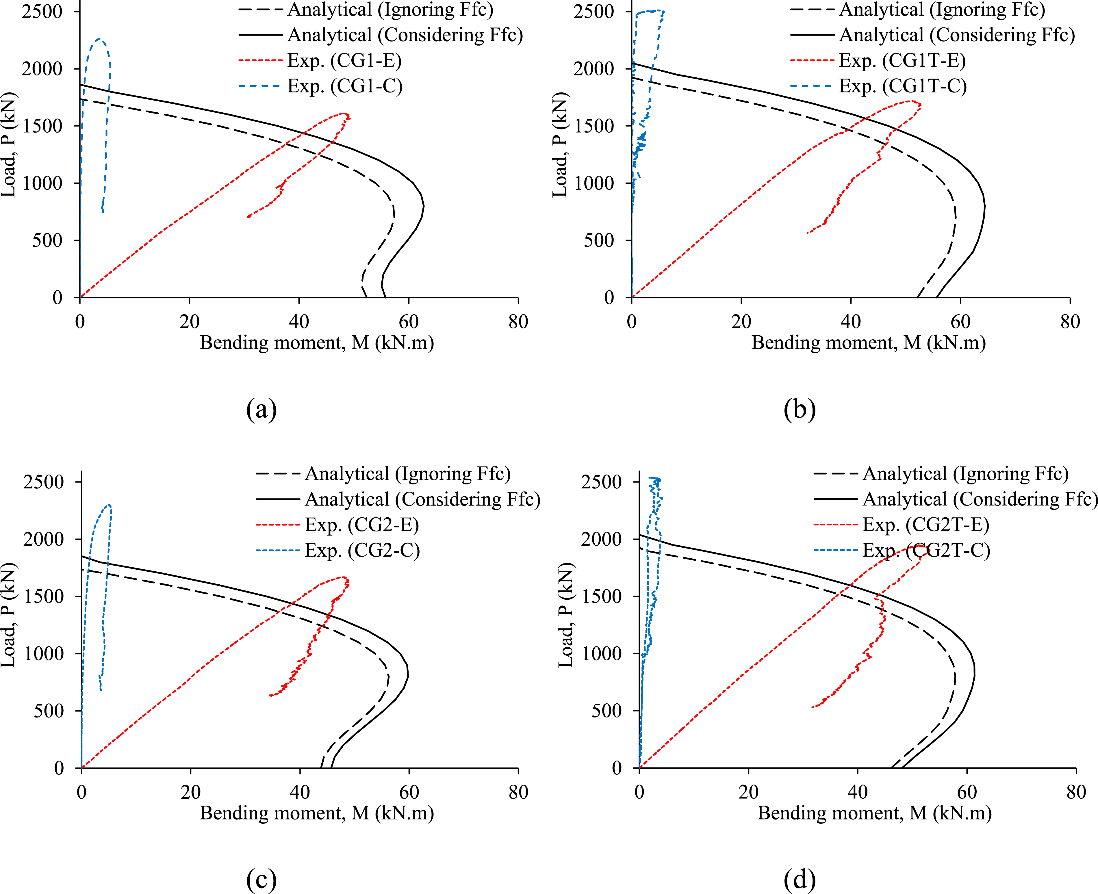
The diagrams displaying the interaction between load (P) and moment (M) for columns having both steel and GFRP bars can be depicted in Figures 17 and 18. These diagrams were generated using equations (6) and (7). The inclusion of the compressive resistance of GFRP bars led to the enlargement of the P-M diagram. Additionally, the experimental P-M diagrams for specimens with concentric and eccentric compression are also depicted in these figures. When drawing the experimental diagrams, the moment (M) is determined as the sum of two components: the moment resulting from the first eccentricity (e), which is zero for columns under concentric compression and 25 mm for columns tested under eccentric compression, and the moment due to the transverse mid-height displacement (Δ). While the predictions closely match for specimens containing steel bars, the predictions for specimens containing GFRP rebars are conservative due to the limitation imposed on the compressive strain in GFRP rebars. P-M interaction diagrams and experimental P-M diagrams of columns reinforced with steel rebars: (a) having no steel tube (CS1); and (b) having a steel tube (CS1T). P-M interaction diagrams and experimental P-M diagrams of GFRP-reinforced columns: (a) CG1; (b) CG1T; (c) CG2; and (d) CG2T.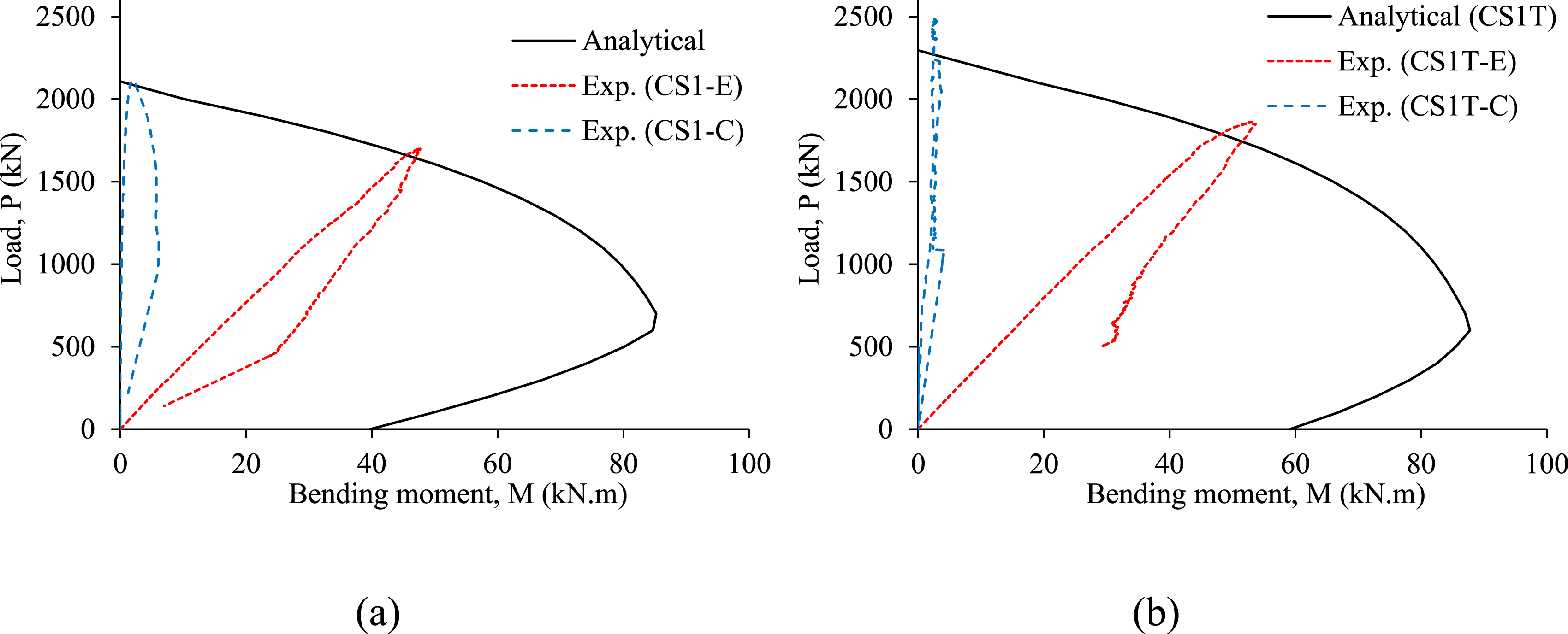
Conclusions
The present research yields the following key findings: (i) In RC columns loaded with concentric or eccentric loads and containing steel bars, the inclusion of a steel tube caused a drop in the post-peak portion of the load-deformation graphs. This was because the reinforcement offered by the steel tube was lying near the centroidal axis of the column. The primary failure mode for the RC columns involved the crushing of concrete succeeded by buckling of vertical steel bars. (ii) Regardless of the diameter of vertical GFRP rebars, the addition of a steel tube as internal reinforcement in concentrically loaded GFRP-reinforced columns caused a 10% enhancement in the axial capacity. The improvement in the resistance is more than the increase caused by additional reinforcement, which is due to the confinement of concrete inside the tube. (iii) For columns subjected to eccentric compression, the introduction of a steel tube caused an augmentation of the post-peak segment of the load versus deformation curves, consequently improving ductility. Nevertheless, for specimens with concentric load, the addition of a steel tube caused almost no change in the post-peak segment of the curves. Despite the reinforcement provided by the steel tube lying close to the vertical axis of the specimen, the addition of a steel tube introduced ductility in columns tested under eccentric loads. (iv) A model is suggested for assessing the axial resistance of RC columns having vertical GFRP rebars. The equation accounts for the compressive strength of GFRP rebars. When the compressive capacity of GFRP rebars is disregarded in the calculation, the predicted axial capacity significantly deviates from the actual test results. However, by accounting for the compressive capacity of GFRP rebars, the prediction aligns more closely with the test values, regardless of whether the specimens have a steel tube or not. (v) Utilizing the findings from the section analysis, an analytical approach is introduced for the computation of the P-M interaction graphs concerning columns having a blend of FRP (or steel) bars and a steel tube. The model incorporates the compressive characteristics of GFRP bars. In comparison with the experimentally measured P-M plots, the analytically predicted diagrams demonstrated a strong correlation for columns having steel rebars, while being cautiously conservative for specimens containing GFRP rebars. (vi) The inclusion of the compressive resistance of GFRP rebars results in the expansion of the P-M graphs. Although the inclusion of a steel tube in RC columns having vertical GFRP bars caused enlargement of the P-M graph, the enhancement in the moment of resistance of the column section was insignificant due to the increase in the neutral axis depth of and consequent decrease in rebar tensile stresses. However, increasing the size of the tube may be more beneficial with regard to the enhancement in load-bearing capacity and ductility, which needs further investigation.
Footnotes
Declaration of conflicting interests
The author(s) declared no potential conflicts of interest with respect to the research, authorship, and/or publication of this article.
Funding
The author(s) disclosed receipt of the following financial support for the research, authorship, and/or publication of this article: The authors are grateful to the Deanship of Scientific Research, King Saud University, for funding through Vice Deanship of Scientific Research Chairs.