
Abstract
Reinforced concrete structures in wastewater treatment plants (WWTPs) operate under uniquely aggressive conditions, including biogenic sulphuric acid attack, sustained moisture, elevated temperatures, and partial submergence. Although Fiber Reinforced Polymer (FRP) strengthening is well established for bridges and other concrete infrastructure, its application within WWTPs raises concerns regarding bond durability and long-term performance, and field case studies in such environments remain scarce. This paper presents the structural assessment and Carbon Fiber Reinforced Polymer (CFRP) rehabilitation of an industrial WWTP equalisation tank in Sri Lanka, in which a defective construction joint within an interior column had triggered progressive deterioration after 15 years of service, producing slab deflections of over 250 mm (span/32) far exceeding the BS 8110 serviceability limit of span/250. A multistage investigation combining visual crack survey, scanning electron microscopy (SEM-EDX), and three-dimensional finite element analysis identified two coexisting deterioration mechanisms: wastewater ingress through the defective joint, causing reinforcement corrosion and column fracture; and biogenic sulphuric acid attack within the tank headspace, producing ettringite formation in the slab and beam soffits. Rehabilitation was carried out under operational constraints, comprising column reconstruction, epoxy crack injection, externally bonded CFRP strengthening with elevated temperature post curing at 55–65°C to enhance the cured adhesive Tg, and protective finishing. An environmental reduction factor of 0.80, supported by accelerated ageing and lap shear bond data, was adopted in the strengthening design. Post rehabilitation analysis confirmed restoration of the vertical load path, reduction of peak bending moments, and re-establishment of structural continuity. The paper provides a complete diagnostic to rehabilitation workflow and practical guidance on material selection, surface preparation, post curing, and protective detailing for FRP applications in confined and chemically aggressive service environments.
Keywords
Introduction
Wastewater treatment systems are among the most critical components of modern public health and environmental protection infrastructure. Their continuous operation safeguards water quality, prevents the spread of waterborne disease, and maintains ecological balance, while even short-term disruptions can lead to severe ecological and economic consequences (Kerpelis et al., 2023; Wessberg and Molarius, 2008). The scale of this infrastructure is significant: in the European Union alone, nearly 18,000 wastewater treatment plants (WWTPs) and over three million kilometres of sewer networks are in continuous operation (Woyciechowski et al., 2021), and globally, WWTPs treat in the order of 515 million m3 of wastewater per day (Jones et al., 2014; Ranganathan et al., 2007). Maintaining the structural integrity and uninterrupted performance of these systems is therefore essential.
Despite being designed for decades of service, the structural components of WWTPs and sewer networks operate under particularly aggressive conditions. Reinforced concrete (RC) elements are exposed to corrosive environments above and below the waterline, sustained operational stresses, variations in earth pressure, chloride and sulphate ingress, and microbially induced corrosion, all of which contribute to deterioration over time (Jaskulak et al., 2022; Lambert and Woodward, 2011; Scheperboer et al., 2021; Younis and Knight, 2010). Errors in original design and poor construction practice can further accelerate this deterioration, generating significant safety concerns and risk of socio-economic loss if rehabilitation is delayed (Li et al., 2021; Woyciechowski et al., 2021). Failures in such systems are typically classified as either structural; for example, reinforcement corrosion, cracking, and concrete spalling or operational; including blockages and groundwater infiltration (Marquez et al., 2021; Woyciechowski et al., 2021). Assessing their true structural condition remains technically challenging, inspections often require service interruption and expose workers to hazardous gases, while widely used non-destructive methods such as closed circuit television (CCTV) and sensor-based evaluations have been shown to miss up to 25 % of actual damage (Dirksen et al., 2013). Correlations between visual inspection data and material deterioration measured from core samples are also frequently weak (Scheperboer et al., 2021; Stanić et al., 2017), and long-term ageing data for wastewater infrastructure remains limited (Woyciechowski et al., 2021).
The consequences of even temporary WWTP failures are not hypothetical. In 2003, a sensor failure at the Kaukas industrial WWTP in Finland caused severe ecological damage to Lake Saimaa and economic losses exceeding €2 million (Wessberg and Molarius, 2008). In 2019, the Czajka WWTP in Warsaw discharged approximately 3.6 million m3 of untreated wastewater into the Vistula River over 12 days, one of the largest such incidents recorded worldwide (Jaskulak et al., 2022). Comparable events include the 2020 Casco Bay incident in Portland, USA, in which an electrical failure released around 140,000 m3 of untreated effluent (CBN NEWS, 2020), and the 2017 Tijuana River discharge of approximately 0.5 million m3 in Mexico (Trávníček et al., 2022). These cases collectively demonstrate that short duration structural or operational failures in WWTPs can produce disproportionate ecological, public health, and economic impacts, underlining the importance of timely and reliable rehabilitation strategies.
Reconstruction of deteriorated wastewater infrastructure is, however, time consuming, capital intensive, and typically requires suspension of service. Conventional retrofitting techniques including concrete or steel jacketing, post tensioning, and the bonding of external steel plates present further drawbacks. They add significant deadweight, are difficult to handle on site, and are themselves vulnerable to corrosion and fatigue (Al-Mahaidi and Kalfat, 2018; Bournas et al., 2015; Şentürk et al., 2022). Fiber reinforced polymer (FRP) composites have therefore emerged as a more durable and sustainable alternative, offering high strength and stiffness to weight ratios, low thermal conductivity, low relaxation losses, electromagnetic transparency, and superior corrosion resistance, while requiring minimal equipment and labour for installation (Khodadadi et al., 2024; Maras and Kantarci, 2023; Ozdemir et al., 2023; Thushanthan and Gamage, 2025; Zhou et al., 2025). FRP design is supported by established codes including ACI 440.2 R, CECS 146, and FIB 14 (de Waal et al., 2017), and several techniques are available such as externally bonded reinforcement (EBR), near surface mounted reinforcement (NSM), embedded FRP bars, and mechanical anchorage of which the EBR method is the most widely adopted owing to its simplicity, cost effectiveness, and minimal intrusion into existing structures (Al-Emrani and Kliger, 2006; Subramanian et al., 2022; Thushanthan et al., 2022).
The effectiveness of EBR based FRP strengthening has been extensively demonstrated for individual structural elements. For axially loaded columns, Zarringol and Zarringol (2016) reported strength increments of 66% and 123% when hollow columns were wrapped with one and three layers of CFRP sheet respectively, with corresponding increments of 36% and 105% when GFRP was used. For flexural members, El Maaddawy and Soudki (2005) showed that CFRP wrapping could restore performance even in severely corroded RC beams, achieving a 73% flexural strength increase in a beam that had lost 31% of its steel mass. Hybrid carbon glass U wrapping has been shown to deliver flexural strength improvements of 114% (Attari et al., 2012). For shear strengthening, configuration matters: experiments by Singh (2013) showed that 45° oriented CFRP wrapping increased shear capacity by 11.9%, while bidirectional wrapping yielded 7.7%; sheets oriented at 0° or 90° were ineffective in controlling diagonal cracks (Ary and Kang, 2012). FRP based methods have also been deployed for the dynamic strengthening of structural members against blast, impact, and seismic loads (Dong et al., 2012; Iacobucci et al., 2003; Pham and Hao, 2016; Tang and Saadatmanesh, 2003). On the basis of these findings, FRP retrofitting has now been successfully applied to bridges, tunnels, parking structures, and other reinforced concrete infrastructure (Liu et al., 2020; Pan and Leung, 2009). However, despite this widespread adoption, no published study to the authors’ knowledge has documented the application of FRP strengthening within an operational WWTP a gap of practical significance given the scale, vulnerability, and operational criticality of such infrastructure.
A central reason for this gap is the durability concern associated with using polymer-based composites in aggressive chemical and microbial environments. Long term exposure to sulphates, chlorides, and other harsh agents has been shown to reduce the mechanical performance of FRP composites and their adhesives (Böer et al., 2013; Cabral-Fonseca et al., 2018; Gamage et al., 2006, 2015, 2016; Thushanthan et al., 2022; Thushanthan and Gamage, 2025). The ACI 440.2R (2017) classifies WWTPs as aggressive exposure environments and recommends environmental reduction factors (CE) of 0.85, 0.50, and 0.70 for carbon, glass, and aramid FRP systems respectively; these factors apply to the strength and strain capacity of the composite but not to the modulus of elasticity, which is generally unaffected by environmental exposure (Thushanthan and Gamage, 2025). Increasing the glass transition temperature (Tg) of the adhesive has also been shown to substantially improve resistance to such conditions (Bernaczyk et al., 2023; Gamage et al., 2015, 2016). These findings highlight the need for careful material selection, design, and installation in FRP based rehabilitation of wastewater infrastructure, and reinforce the importance of documented field case studies to support engineering practice.
The aim of the present study is therefore to investigate, through a documented field case study, how localised construction defects can trigger system-level structural deterioration in liquid retaining wastewater infrastructure, and to evaluate the effectiveness of CFRP composites as a non-disruptive rehabilitation material under such aggressive conditions. The study addresses three questions: how the dominant deterioration mechanisms in an operational WWTP equalisation tank can be reliably identified through combined visual, structural, and microstructural investigation; to what extent a CFRP based rehabilitation strategy can restore the structural performance of severely distressed reinforced concrete elements without requiring extended service interruption; and what practical considerations relating to substrate preparation, adhesive selection, post curing, and protective detailing are critical for the successful application of CFRP in confined and chemically aggressive environments.
The case investigated is an industrial WWTP equalisation tank in Sri Lanka, where a critical interior column had developed significant structural deterioration after 15 years of service. CFRP composites were selected to demonstrate a practical, durable, and minimally disruptive alternative to conventional reconstruction. The novelty of the work lies in three interconnected contributions. First, the study presents a documented field application of CFRP strengthening within an operational WWTP, an environment in which such applications have not previously been reported in the published literature, despite the established suitability of FRP for aggressive, corrosion intensive environments and its widespread use in bridges, tunnels, and parking structures. Second, the study integrates a complete engineering workflow rarely brought together in the FRP literature, encompassing a detailed crack survey, microstructural investigation using scanning electron microscopy (SEM-EDX), root-cause analysis, structural analysis, and field implementation of CFRP strengthening with a documented installation procedure, moving beyond the laboratory and component scale studies that dominate the field. Third, the study contributes real world evidence from a tropical, high humidity context that differs substantially from the European and North American settings in which most existing FRP durability data have been generated. The investigation identified two coexisting deterioration mechanisms joint-induced wastewater ingress and biogenic sulphuric acid attack and demonstrated that CFRP-based rehabilitation, supported by accelerated ageing and lap-shear bond test data, elevated temperature post-curing, and a conservative environmental reduction factor of 0.80, can effectively restore the structural performance of severely deteriorated reinforced concrete elements in such environments.
Project background
The equalisation tank considered in this study is part of the WWT facility located within the Seethawaka Export Processing Zone (EPZ), Sri Lanka. [Figure 1(a)]. An aerial view of the facility is shown in Figure 1(b). The EPZ covers an area of 431 acres, of which 183 acres are occupied by major industries, contributing approximately USD 297 million in export revenue in 2018 (Board of Investment of Sri Lanka, 2019). Given the highly industrialised nature of the zone, the wastewater generated is classified as industrial effluent. Industrial discharges are typically characterised by large variations in influent flow rate and composition, which can adversely affect downstream treatment processes. To mitigate these fluctuations, an equalisation tank is incorporated into the treatment facility to stabilise flow conditions and optimise the performance of subsequent treatment stages. The side elevation, top view, and capacity details of the equalisation tank are shown in Figure 1(c)–(e). (a) Satellite view of the Seethawaka Export Processing Zone and WWTP (b) Aerial view of the WWTP facility and its components (c) Side elevation of the equalisation tank (picture taken from the east side of the tank) (d) Top view of the tank (e) Equalisation tank details displayed on the tank wall (f) EPZ wastewater treatment plant flow diagram incorporating flow equalisation (g) Plan view of the equalisation tank.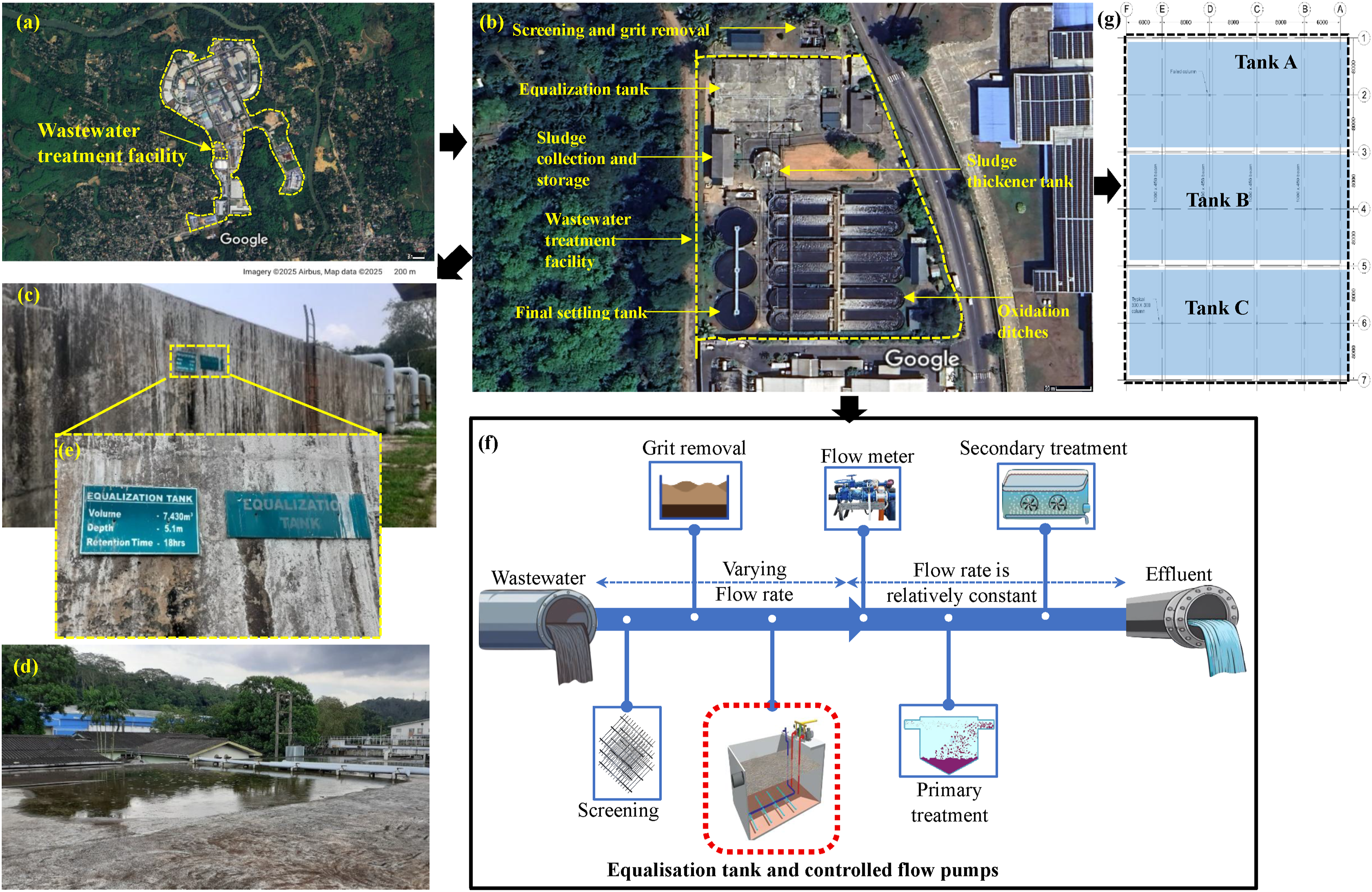
Wastewater from the grit chamber first enters the equalisation tank, from where it is released to the primary treatment units at a constant or near constant rate, thereby improving process efficiency (Tchobanoglous et al., 2003). The functional role of the equalisation tank is critical, as it regulates flow, buffers hydraulic and pollutant load variations, moderates temperature fluctuations, and ensures homogeneous mixing of the wastewater. These functions collectively enhance the performance of the biological treatment processes downstream. The overall process flow of the Seethawaka WWTP is illustrated in Figure 1(f).
Commissioned in 1999, the total storage capacity is 7430 m3, with an average hydraulic retention time of 18 hours, and the tank has a depth of 5.1 m [Figure 1(e)]. The Seethawaka equalisation tank comprises three equal compartments that temporarily store wastewater prior to primary treatment, as shown in the plan view in Figure 1(g). The roof slab comprises one-way spanning panels with exterior and interior spans of 6000 mm and 8000 mm respectively, and a thickness of 175 mm. The slabs are supported by beams 1000 mm wide and 450 mm deep. The slab reinforcement consists of 16 mm diameter deformed steel bars at 200 mm spacing as primary reinforcement, with 12 mm diameter deformed steel bars at 200 mm spacing provided as secondary reinforcement. However, the drawings do not specify the compressive strength of the concrete, the tensile strength of the steel, or the concrete cover to the reinforcement.
The roof beams span between reinforced concrete walls and columns, and certain areas of the roof slab support plumbing equipment. During operation, the tank compartments are not designed to be completely filled, and a freeboard is consistently maintained, although its height varies depending on the inflow rate from the factories throughout the day. The top of the tank is fully exposed to sunlight, subjecting the slab surface to cyclic temperature and humidity changes; notably, the soffit temperature of the slab has been recorded to reach approximately 42°C during the daytime.
Site inspection
Visual inspection of the tank
Operation of Compartment A [Figure 1(g)] was temporarily suspended in 2015 following the observation of excessive deflections and cracking in the interior roof slab panels. At mid span, three of the panels exhibited deflections exceeding 250 mm, the severity of which was evident from the stagnation of rainwater on the roof slab [Figure 2(a-1)]. With reference to the original design span of 8000 mm, this corresponds to a deflection to span ratio of approximately span/32, far in excess of the serviceability limit of span/250, indicative of severe structural distress rather than a serviceability concern. Pronounced mid span deflections, accompanied by visible cracking, were also observed in several adjacent panels [Figure 2(a-2) to (a-3)]. (a) (1) Water to stagnation on deflected slab panel (2) cracks on top of the slab panel (3) cracks on wall and slab joint (b) (1) intermediate column separation through construction joint (2) lateral deflection of the ventilation pipe due to change in vertical load path (c) (1) coarse aggregate are exposed and started to dislodge from the surface of the beam (2) concrete corrosion on the wall.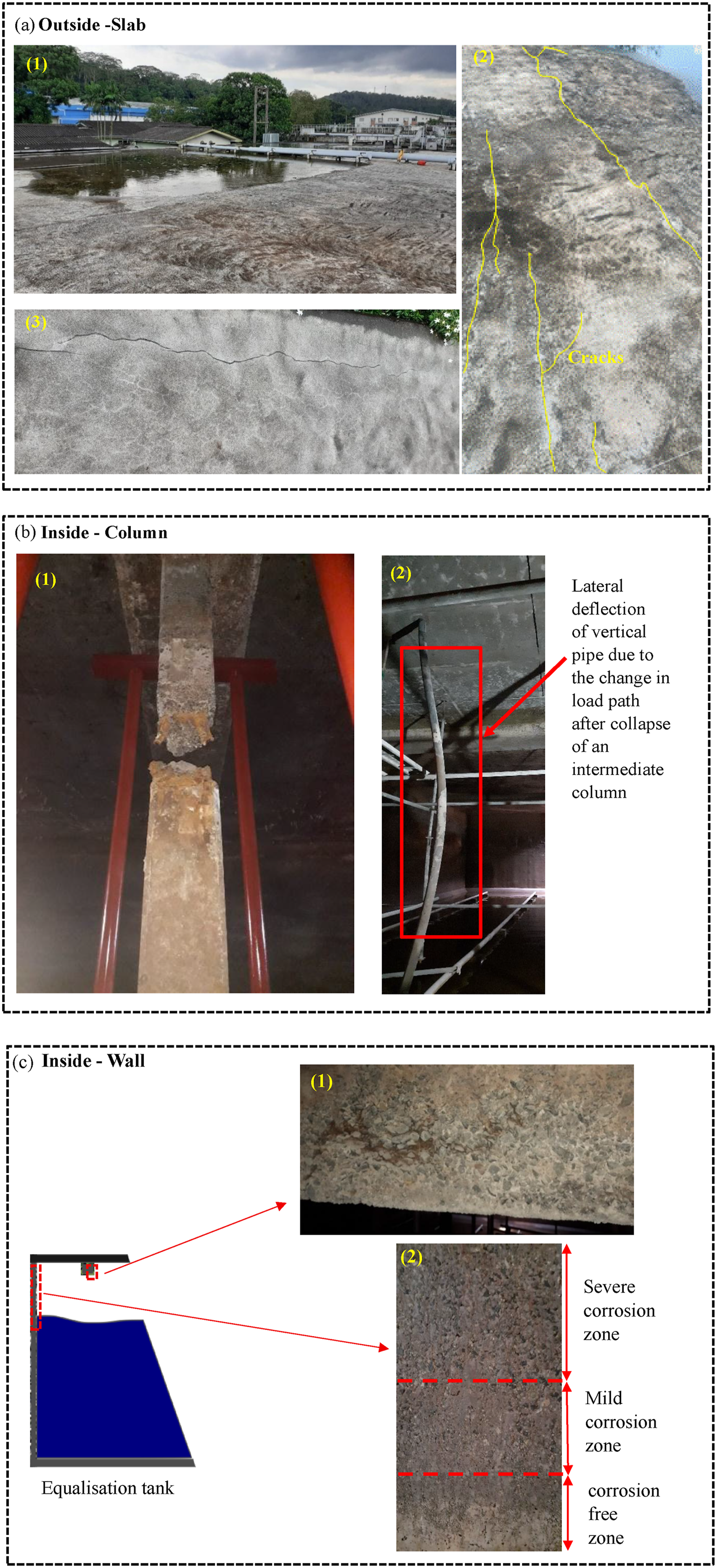
At the time of the initial inspection, the tank compartments remained in operation and internal access was not feasible. Based on the external observations, it was initially hypothesised that settlement of an intermediate column had contributed to the slab deflections. To verify this, a borehole investigation was undertaken at three locations adjacent to the tank. The subsurface profile revealed a 2.2 m thick layer of weak fill near the surface; however, this was not considered structurally critical, as the foundation formation level lay beneath the fill and was supported by relatively stiff underlying strata. The hypothesis of foundation settlement was therefore discounted.
Non-destructive testing was subsequently carried out to assess the extent of structural deformation and material degradation. The results indicated that the structural system could remain in service provided that appropriate strengthening measures were implemented. Two strengthening priorities were identified: first, enhancing the flexural, shear, and torsional capacity of the slabs, beams, and wall slab intersections; and second, improving the axial confinement of the columns so that the structure could safely re-establish its intended load path. Crucially, the strengthening strategy was required to avoid any significant addition of self-weight, given the limited reserve capacity of the existing foundation and the practical difficulty of strengthening it from below an operational tank.
To facilitate a detailed internal inspection, the influent inlets to Compartment A were closed and the wastewater drained through the outlets. Suction fans were then deployed to extract sewer gases and ensure safe working conditions for the inspection team. Internal inspection revealed that an intermediate column had fractured into two distinct sections, with the exposed reinforcement exhibiting significant corrosion [Figure 2(b-1)]. The adjacent columns also displayed slight lateral deflections, and lateral displacement of the vertical pipelines provided further evidence of a disturbed load path resulting from the column failure and the associated slab deflections [Figure 2(b-2)]. As a consequence, the roof beams supporting the slab had also undergone noticeable deformation.
Evidence of concrete corrosion was observed both in the failed column and in the surrounding walls. The wall corrosion was most severe near the roof slab and diminished progressively with depth [Figure 2(c)], a pattern consistent with attack driven by sewer gas accumulation in the headspace above the wastewater. To prevent further structural deterioration and the possibility of progressive collapse, galvanised steel (GI) pipe props were installed adjacent to the damaged column as a temporary measure. The operation of Compartment A was thereafter fully suspended pending renovation. The plan location of the deteriorated elements is indicated in Figure 3. Crack survey locations on top of the tank.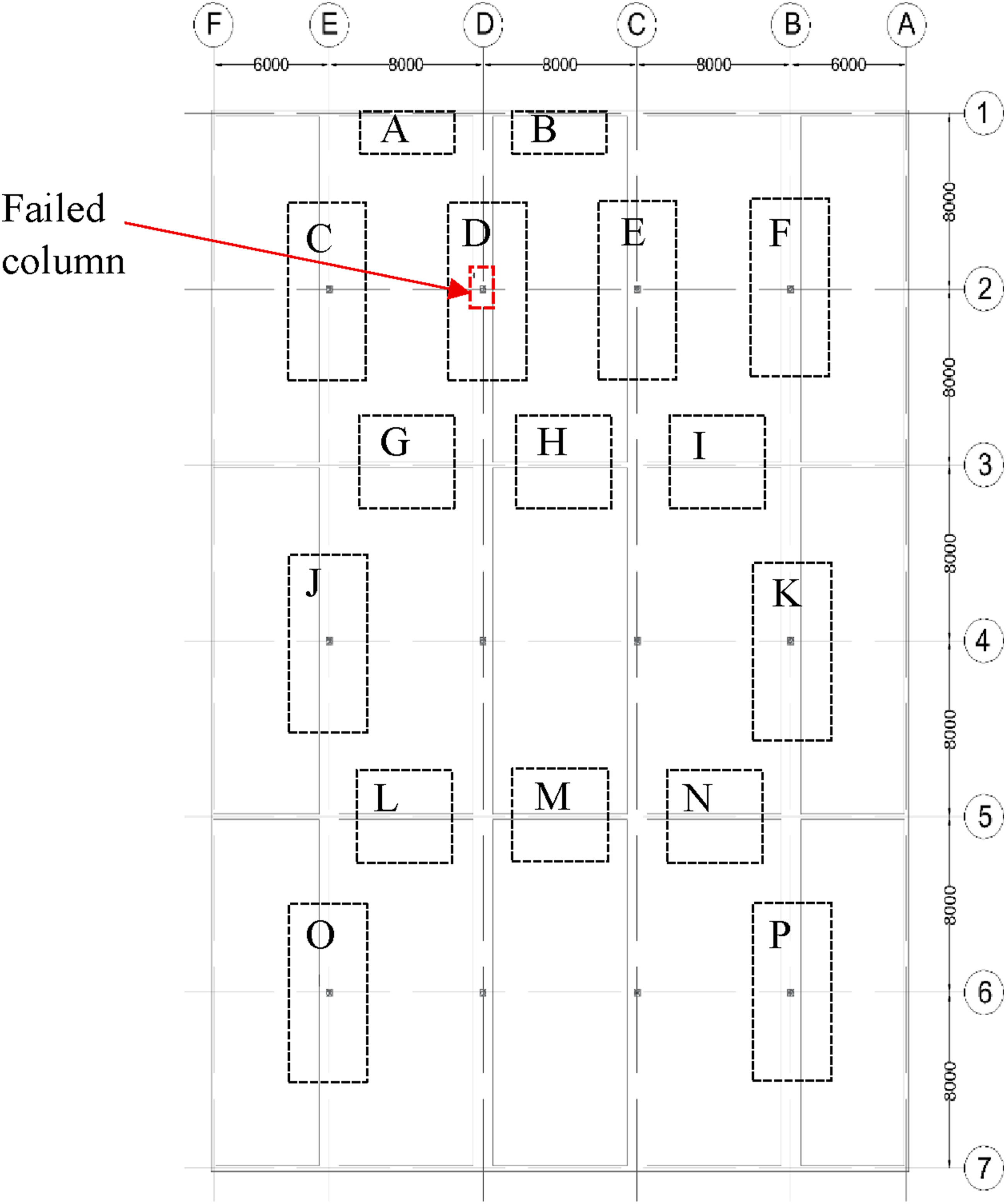
Crack survey on the top of the slab
A crack survey was carried out during the on-site inspection to evaluate the extent of structural deterioration on the upper surface of the roof slab. Cracks with a width greater than 0.3 mm were recorded, in line with the threshold below which cracking is generally considered cosmetic rather than structurally significant. A total of 16 locations across the roof slab were identified for inclusion in the survey, as illustrated in Figure 3. A detailed discussion of the observed crack patterns and their implications is presented in the Discussion section.
Material and structural analysis
SEM analysis
Concrete samples extracted from the corroded surfaces of the beam and slab were examined using a SEM operated at an accelerating voltage of 10 kV. The investigation was carried out to identify microstructural features associated with the principal deterioration mechanisms anticipated in this environment namely, sulphate attack and microbially induced corrosion.
Structural analysis of the tank
A three-dimensional finite element model of the tank was developed and analysed using the commercial structural analysis software Midas Gen (Midas Co, 2024). Two cases were considered.
The first represented the structure in its existing deteriorated state, with the failed intermediate column and the deflected slab modelled as observed on site. The second represented the post-rehabilitation structure following reconstruction of the failed column and reinstatement of the slab to a level profile, with a lightweight infill material varying in thickness from 20 mm to 250 mm applied to compensate for the residual deformation. The numerical models for both cases are illustrated in Figure 4(a) and (b). (a) Numerical model of the current state of the tank without column (Roof slab elements are hidden) (b) numerical model of the tank after re-construction of the column and lightweight material fill on the slab for aesthetic appearance (roof slab elements are hidden).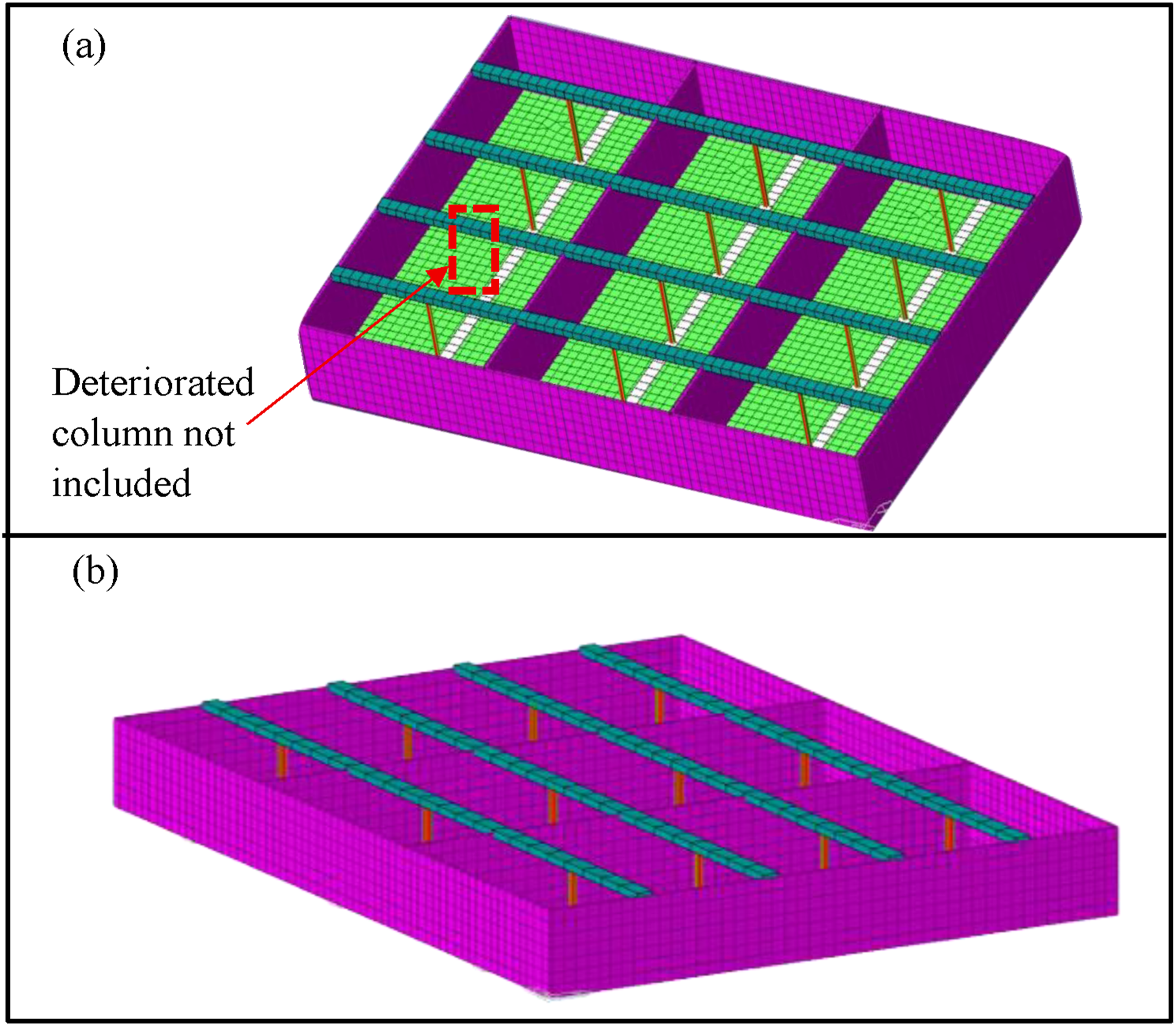
To account for material degradation, the compressive strength of all concrete members was reduced by 30%, giving an assumed in-situ strength of 28 MPa, and the yield strength of the existing reinforcement was reduced by 20%–50% depending on the location and extent of observed corrosion, giving an assumed in-situ yield strength of 370 MPa. These reductions were informed by the visual inspection, NDT results, and SEM analysis described in the preceding sections.
Beams and columns were idealised as line (frame) elements, while slabs and walls were represented by two-dimensional plate elements. The predicted member forces and moments were independently verified through hand calculations using simplified beam and slab idealisations. Existing and required design capacities were computed in accordance with BS 8110-1(1997), the code under which the original structure was designed. On the basis of these calculations, CFRP strengthening was selected to enhance the load bearing capacity of deficient members, with CFRP sheets and plates chosen according to the specific capacity requirement and the geometry and accessibility of each member. The mechanical properties of the CFRP and epoxy resin used in the project are summarised in the Supplemental Material [Annex-A: Table-1]. The strengthening design was carried out in accordance with ACI 440.2R (2008).
Results and discussion
Crack survey
The crack survey revealed extensive cracking distributed across the 16 inspection locations identified in Figure 3, with crack widths ranging from approximately 0.75 mm to 1.25 mm. The observed patterns and their interpretation are summarised below, with the principal observations illustrated in Figure 5. Schematic diagram of bending moment generation and crack formation on the slab due to the separation of the column (a) crack formation at wall slab joint (b) positive bending moment at tank A slab (b) negative bending moment at Tank B slab (c) positive bending moment at tank C top.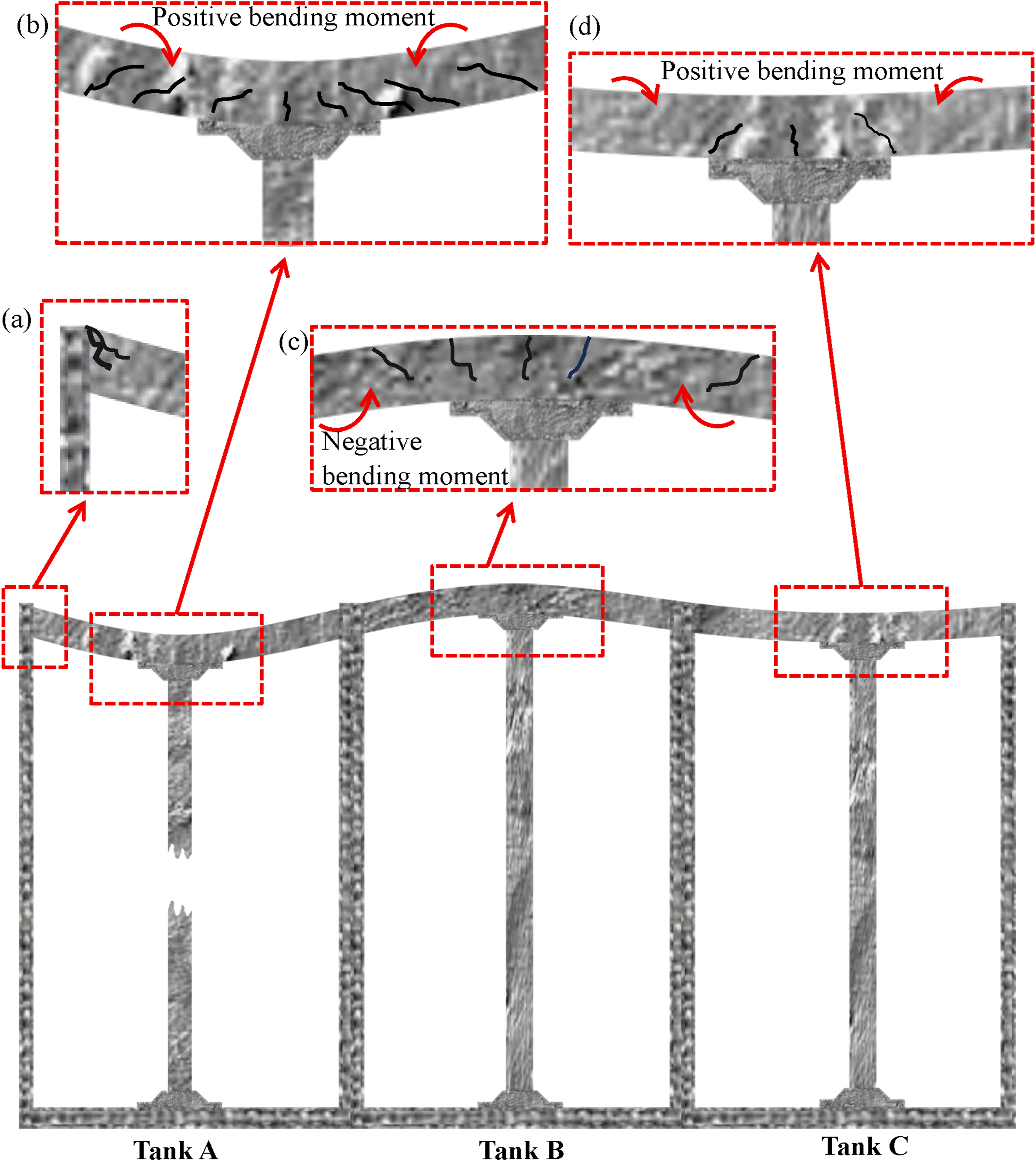
The most severe cracking was recorded at locations A and B, immediately adjacent to the wall-slab joint, where parallel cracks of up to 1.25 mm width were identified. These cracks were oriented parallel to the joint, indicating partial separation between the wall and the slab. The pattern is consistent with sagging of slab panels E-D/1-3 and D-C/1-3 above the failed intermediate column, which has imposed tensile stresses on the slab-wall junction beyond the tensile capacity of the concrete.
At locations C and E, two cracks of approximately 0.75 mm width were observed on either side of beams E/1-3 and C/1-3 respectively. Both locations are adjacent to the most heavily deflected panel, E-C/1-3. The cracking is attributed to tensile stresses generated by the excessive deflection of this panel, exceeding the tensile strength of the cover concrete and producing flexural cracks aligned with the principal moment direction. Location D, in the central region of the deflected panel, exhibited no visible cracking consistent with the predominantly compressive stress state at this location under positive bending; should the deflection progress further, the compressive stresses could approach the concrete crushing strength and initiate compressive surface damage.
Cracking at location F was identified along beam B/1-3 and is attributed to negative bending moments induced in the supporting beam by slab deflection the same mechanism responsible for cracking at C and E. The lower crack intensity at F reflects the smaller negative bending moments developed in this region.
Locations G, H, and I exhibited multiple parallel cracks aligned with the longitudinal direction of the supporting wall. The crack density was noticeably higher than at A and B, again attributed to negative bending moments induced by deflection of the adjacent panels. The higher density relative to A and B reflects the greater rotational restraint provided by the continuous wall along this edge, which concentrates the negative bending moment region and produces more numerous but finer cracks rather than fewer, wider ones.
The crack patterns at locations J and O, and at K and P, were broadly comparable to those at A and B, though the widths were smaller. Locations L, M, and N exhibited fewer and narrower cracks than G, H, and I, but their orientation and distribution were consistent with the same underlying flexural mechanism, indicating that the deflection driven stress field extends across a wide region of the slab beyond the immediate vicinity of the failed column.
Taken together, the survey indicates that the dominant cause of cracking is excessive deflection arising from the failure of the intermediate column, which redistributed the load path through the surrounding frame and generated tensile stresses exceeding the tensile capacity of the concrete in regions of both positive and negative bending. The combination of cracking parallel to the wall-slab joints, transverse cracking along the beam lines, and longitudinal cracking adjacent to the supporting walls is characteristic of a structural system that has progressively adapted to the loss of one of its principal vertical supports consistent with the behaviour expected following column loss in a continuous reinforced concrete frame, with the slab and beam system mobilising secondary load paths through flexure, two-way action, and rotational restraint at the supports.
SEM analysis results
The SEM-EDX analysis of samples extracted from the soffit of the slab and beam is presented in Figure 6 (a)-(c). The micrographs revealed distinct needle-like crystalline formations within the deteriorated concrete matrix, with morphology consistent with ettringite as reported in previous studies and confirmed by the elemental peaks observed in the EDX spectra (Mirvalad, 2013; Mittermayr et al., 2012). (a) Degradation of the concrete matrix and cracks formation (b) expansive ettringite formation in the concrete matrix (c) EDX analysis of the deteriorated concrete matrix indicating the ettringite formation C3A.3CaSO4.32H2O.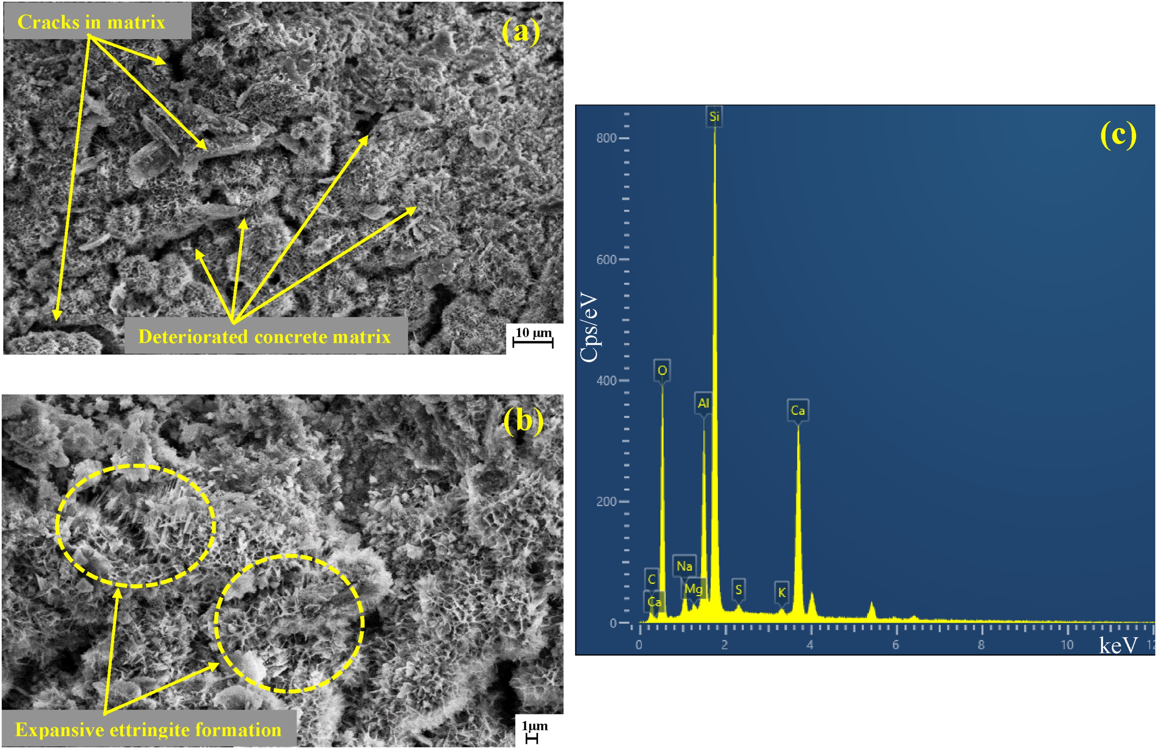
The stability of ettringite is strongly influenced by the alkalinity of the surrounding pore solution. Day (1992) reported that ettringite crystals remain stable at pH 11.5–11.8, whereas at pH 12.5–12.8 the same composition tends to occur in a non-crystalline phase, and Hadigheh et al. (2017) similarly observed ettringite formation in the range pH 12.0–12.5. Although ettringite rarely develops on the external surfaces of sewer structures, where surface pH can fall to as low as 3 owing to biofilms of sulphur-oxidising bacteria, the pore solution within sound concrete typically maintains a pH close to 13 (Justin et al., 2025; Wang et al., 2017). This high internal alkalinity favours the crystallisation of ettringite deeper within the matrix, even where the external surface has been acidified.
The formation of ettringite from the reaction of calcium aluminate phases (C3A) with calcium hydroxide and sulphate ions is well known to cause significant volumetric expansion. Lafuma (1929) noted that calcium aluminate phases are difficult to distinguish when coexisting with calcium hydroxide, but that their solid-state conversion to ettringite can produce a volume increase of up to eight-fold (Mehta, 1973). The internal tensile stresses generated can exceed the tensile strength of the cement matrix, leading to micro-cracking, mechanical degradation, and ultimately loss of structural integrity (Hadigheh et al., 2017; Mehta, 1973).
In the present case, the operational environment of the equalisation tank is highly conducive to sulphate attack of the type associated with microbially induced concrete corrosion (MICC), shown schematically in Figure 7(a) and (b). Hydrogen sulphide (H2S) gas, generated within the headspace by the metabolic activity of sulphate-reducing bacteria in the wastewater, condenses on the soffits of the slab and beams, where it is oxidised by sulphur-oxidising bacteria to biogenic sulphuric acid (H2SO4). The acid attacks the cementitious matrix, depletes surface alkalinity, and drives sulphate ions into the concrete, where they react with calcium aluminate phases to form expansive ettringite. This biogenic mechanism is significantly more aggressive than conventional liquid-phase sulphate attack, owing to the localised acidic environment and continuous regeneration of reactants at the gas-concrete interface (Woyciechowski et al., 2021). (a) Schematic diagram of the microbially induced concrete corrosion in wastewater systems (b) stages of microbially induced concrete corrosion (MICC) in wastewater/sewer systems.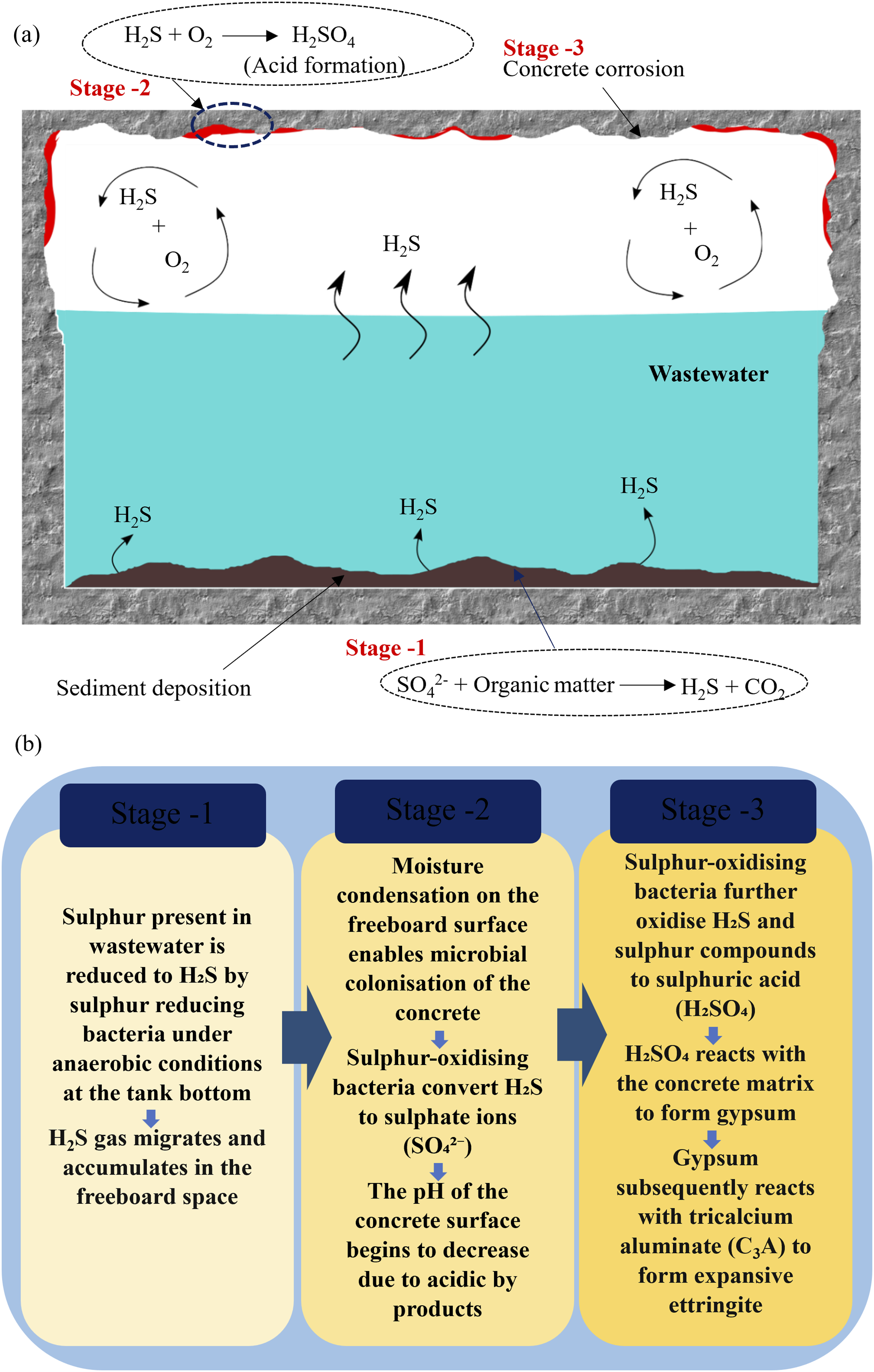
The identification of ettringite in the SEM samples therefore confirms that the structural members of the tank, particularly the soffits of the beams and slabs, continuously exposed to the H2S-laden headspace have undergone sulphate induced microstructural deterioration. This finding is consistent with the visible distress observed during the site inspection: surface concrete deterioration on the wall and column elements, most pronounced near the roof slab as described in the visual inspection of the tank section, and the development of cracking in the soffit regions of the beams and slabs.
Structural analysis results
Comparison of slab bending moments, shear forces, and deflections before and after rehabilitation.
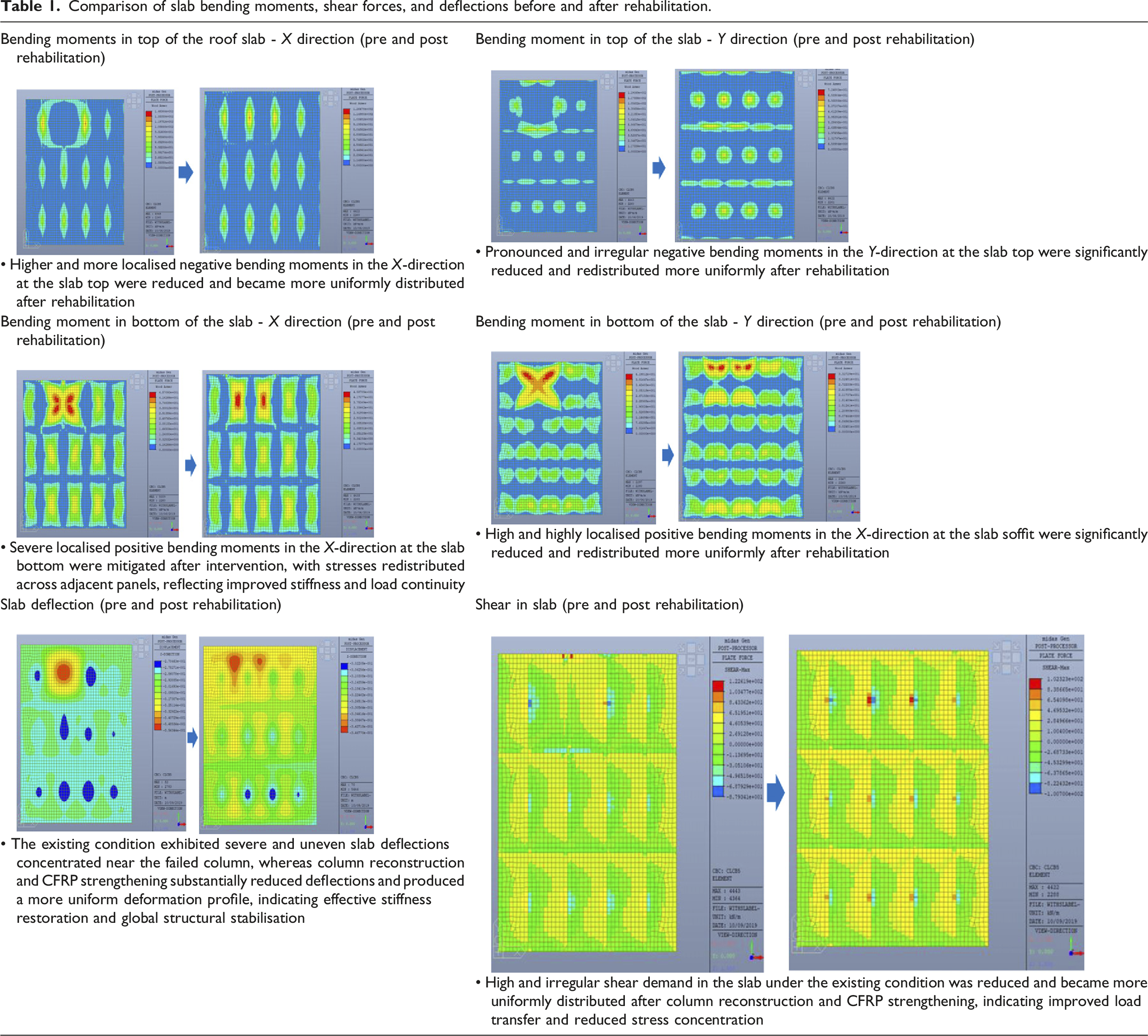
The predicted deflection of 356 mm exceeds the field measured value of 250 mm. This difference is attributed to the use of reduced material properties that conservatively account for ageing and corrosion induced degradation, the application of ultimate limit state load combinations, and the model’s inability to capture partial composite action with adjacent slabs that may have contributed to load redistribution and reduced actual deflection. The model therefore provides a conservative envelope of structural demand, appropriate for the design of the rehabilitation strengthening. A detailed comparison of the finite element results for both configurations, including the influence of the lightweight levelling overlay, is provided in the Supplemental Material [Annex-B: Table-2 to 3].
Following reinstatement of the failed column in Case 2, the bending moments in slab panel C-D/1-3 reduced to values comparable with those in the adjacent panels. The peak negative bending moments along the Y direction at the soffit of panel C-D/1-3 were significantly reduced, indicating that reconstruction of the column had restored the vertical load transfer path and substantially relieved the localised stress concentrations in the distressed region.
Although the present study did not involve laboratory load deflection testing of isolated slab specimens, the pre and post rehabilitation finite element results provide a system level indication of stiffness recovery. Under comparable loading conditions, the rehabilitated model exhibited improved load sharing among the slab panels, a reduction in localised moment concentration, and lower predicted incremental deformation demand. These effects correspond to an increase in the effective stiffness of the slab system, achieved through the combined effect of three interventions: reinstatement of the failed column, restoration of the vertical load path, and CFRP strengthening of the deficient slab and beam regions.
The analysis further demonstrated that the columns did not require CFRP strengthening for either axial load or flexural capacity, as their reduced capacities calculated using the degraded material properties described in Section 4.2 remained sufficient under the ultimate limit state load combinations. Similarly, shear strengthening of the beams was not required, with the exception of the most heavily deflected beam adjacent to the failed column. By contrast, the severely deflected slab panels and their associated beams required CFRP strengthening to enhance both their positive and negative bending moment capacities, and to restore the effective stiffness and load carrying capacity of the roof slab system.
Direct field measurement of early strain development at the slab wall and slab beam junctions was not feasible during the inspection, owing to restricted access within the operational tank and the hazardous internal environment. Strain demand was therefore inferred through combined interpretation of crack widths, crack orientations, and the tensile moment regions predicted by the FE model. The most severe tensile cracking was observed at the wall slab and beam slab junctions, with maximum recorded crack widths of 1.25 mm and 0.75 mm respectively, coinciding closely with the zones of elevated hogging moments predicted by the analysis. Following the modelled column reconstruction and CFRP strengthening in Case 2, bending moments redistributed away from these previously distressed junction regions, consistent with reduced tensile strain concentration and improved continuity of force transfer. Although direct strain measurements were not available, the close correspondence between the crack survey observations and the FE predicted tensile demand provides a quantitative basis for identifying the critical strain concentration zones.
The structural implications of the lightweight levelling overlay were also explicitly considered in the post-rehabilitation model. Since the original slab had already developed permanent deflection, the overlay thickness was varied across the affected panels from approximately 20 mm to 250 mm to restore the surface to a level profile and prevent future rainwater ponding. The overlay was modelled in Case 2 as an additional permanent dead load applied alongside the reconstructed column and CFRP strengthened slab system. The resulting bending moments, shear forces, and deflection demand were checked against the available member capacities, accounting for the degraded material properties and CFRP strengthening contributions. Although the overlay increased the gravity load on the roof slab, the reinstated column restored the vertical load-transfer path and the CFRP system provided the additional flexural capacity required. The analysis confirmed that the rehabilitated configuration satisfied all required capacity checks, indicating that the overlay did not compromise the structural safety of the restored tank.
Root cause for the failure
The separation observed in the failed column occurred at its construction joint, whereas no comparable deterioration was identified at the corresponding joints of the other interior columns. This selective failure pattern strongly indicates that the construction joint of this particular column had not been executed to the same standard of workmanship as the others, and that the ingress of wastewater through this defective joint was the primary trigger for the subsequent deterioration.
The corrosion mechanism that developed at the joint is illustrated schematically in Figure 8. Wastewater first penetrated the column through the poorly executed joint [Figure 8(a)]. On reaching the embedded steel reinforcement, the infiltrating water initiated electrochemical corrosion of the steel [Figure 8(b)]. The volumetric expansion associated with the formation of corrosion products is well documented, with reported expansion ratios ranging from 1.2 to 6.9 depending on factors such as the local pH, oxygen availability, corrosion rate, and chloride concentration in the surrounding pore solution (Justin et al., 2025). This expansive pressure generated internal tensile stresses within the surrounding concrete [Figure 8(c)]. Once these stresses exceeded the tensile strength of the concrete, splitting cracks developed along the line of the reinforcement [Figure 8(d)]. Continued corrosion progressively widened these cracks and dislodged coarse aggregate particles from the matrix, creating localised voids in the cover concrete [Figure 8(e-f)]. These voids further increased the permeability of the section, providing an enlarged ingress path for additional wastewater and exposing a greater surface area of reinforcement to the corrosive environment [Figure 8(g)]. The resulting feedback loop corrosion driving cracking, and cracking accelerating corrosion led to the progressive disintegration of the cementitious matrix at the joint, and ultimately to the complete separation of the column into two distinct sections [Figure 8(h)]. (a) Water ingress inside column through construction joint (b) corrosion in steel commence with contact with water (c) internal stress generation caused by reinforcement corrosion (d) induced stresses become higher than tensile capacity of concrete (e) cracks forms inside the concrete (f) coarse aggregates dislodge from concrete matrix (g) water ingress increases due to the formation of void spaces and cracks (h) column separation into two sections.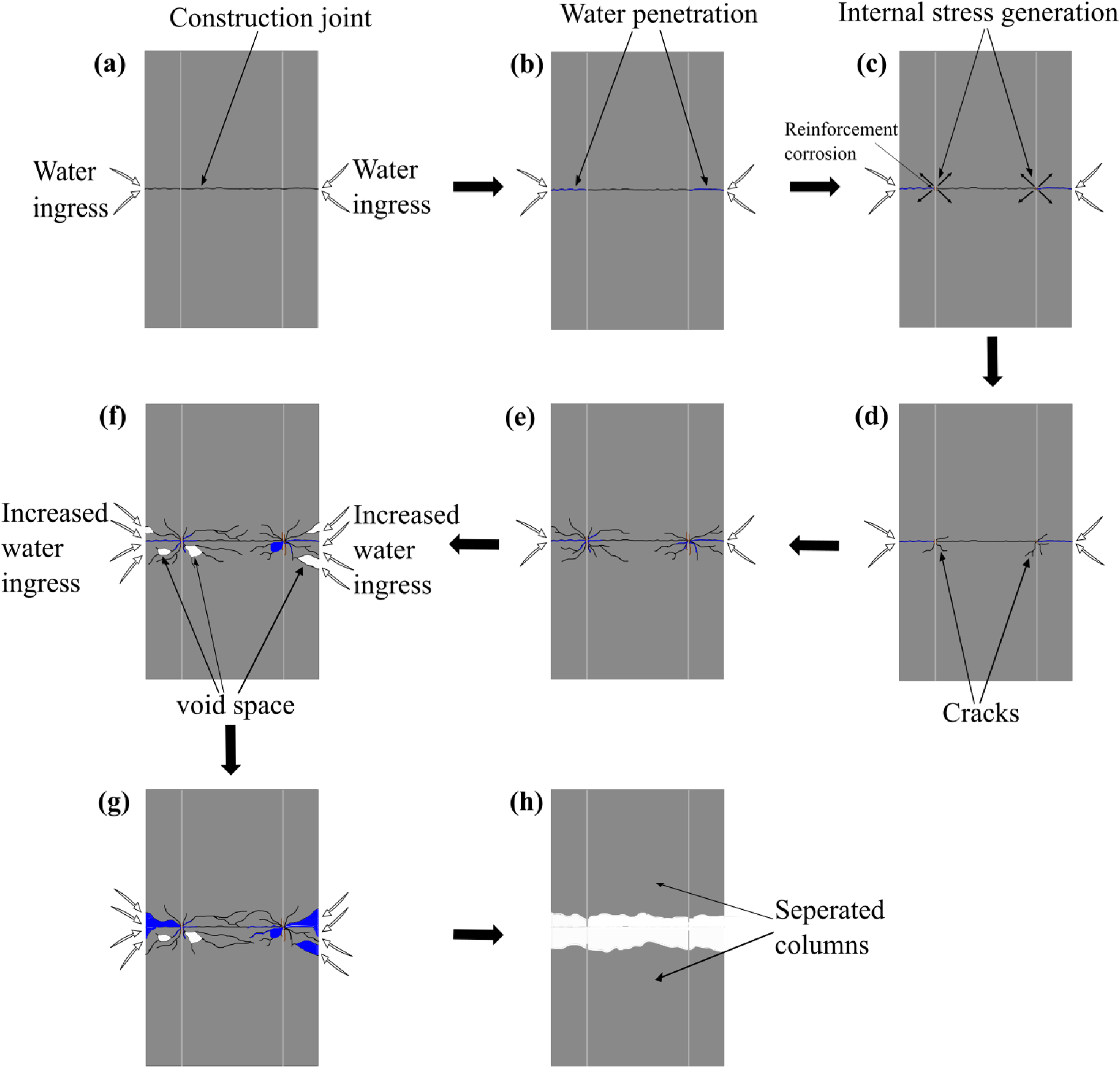
Construction joints are an essentially unavoidable feature of reinforced concrete construction, arising from practical interruptions to casting operations, delays in material supply, or deliberate design measures intended to control thermal contraction and the development of restrained shrinkage stresses. However, if such joints are not properly executed, they can form critical planes of weakness within the structure particularly in liquid retaining elements continuously exposed to water and chemically aggressive agents, where the joint represents the most vulnerable point in the load bearing path.
To ensure adequate bond strength and long-term durability across construction joints in reinforced concrete, well established surface preparation and concreting procedures must be followed when fresh concrete is placed against partially hardened (green) concrete. The joint surface should be cleaned thoroughly to remove laitance, loose particles, and surface contaminants prior to placement, and fresh concrete should be properly compacted by vibration to achieve full intimate contact with the underlying layer. In liquid retaining structures such as equalisation tanks, additional precautions are required: construction joints must be sealed using appropriate waterproof sealants or caulking compounds, and continuous PVC or rubber water stops should be embedded across the joint during construction to prevent the seepage of liquid through the interface. The case presented in this study illustrates the consequences of failing to implement these measures: a single inadequately executed joint, in an otherwise comparable structural element, became the initiation point for a corrosion-driven failure mechanism that ultimately compromised the load-bearing capacity of the entire column and led to the structural distress observed throughout the surrounding frame.
Retrofitting of the structure
Selection of retrofitting material
The selection of fiber type for FRP strengthening is governed primarily by considerations of cost, mechanical performance, and long-term durability under the anticipated service environment. Glass fiber reinforced polymer (GFRP) composites are typically less expensive than CFRP composites and have been used extensively in conventional retrofitting applications. However, GFRP is considerably more susceptible to long-term degradation under aggressive environmental conditions particularly alkaline and acidic exposure, prolonged moisture, and combined chemical thermal action which introduces significant uncertainty regarding its sustained performance over the design service life (Ebrahimzadeh et al., 2025; He et al., 2017; Ji and Kim, 2017; Ouyang and Wan, 2009).
In the present case, FRP strengthening was required for the reconstructed column, and for the soffits of the deflected beams and slab panels. During normal tank operation, the column remains partially submerged in wastewater, while the soffits of the beams and slabs are continuously exposed to a moisture-laden headspace containing biogenic sulphuric acid produced by the microbially induced corrosion mechanism described in Section 5.2. Externally, the upper surface of the tank is exposed to direct precipitation, fluctuating temperatures, and ultraviolet radiation, with soffit temperatures previously recorded to reach approximately 42°C during the daytime (Section 2). The combination of submerged conditions, biogenic acid attack in the headspace, and external climatic exposure represents a particularly demanding service environment for any polymer-based composite.
Based on these combined exposure conditions, CFRP composites were selected as the rehabilitation material. CFRP exhibits superior resistance to alkaline, acidic, and humid environments compared with GFRP and AFRP, and its long-term durability has been demonstrated in a range of aggressive industrial settings (Hadigheh et al., 2017; Thushanthan et al., 2022). The environmental reduction factor (C = 0.85) recommended by ACI 440.2R (2017) for CFRP in aggressive exposure conditions is also less penalising than the corresponding factors for GFRP (CE = 0.50) and AFRP (C = 0.70), reflecting the relative robustness of CFRP under such conditions. The selection of CFRP was therefore driven not only by its mechanical performance but also by its proven durability characteristics in environments comparable to that of the equalisation tank, ensuring a more reliable and longer-term rehabilitation outcome despite the higher initial material cost.
Durability and bond performance of CFRP system under aggressive exposure
The long-term effectiveness of externally bonded CFRP strengthening in wastewater infrastructure depends both on the tensile durability of the CFRP laminate and on the integrity of the concrete-CFRP bond interface. Direct durability and bond-performance evidence for the materials selected was therefore considered essential to justify the rehabilitation strategy adopted in this study.
The durability behaviour of the impregnated CFRP sheets used here was evaluated in a previously published accelerated-ageing investigation by Thushanthan and Gamage (2025). In that study, unidirectional CFRP coupons were exposed to deionised water, a highly acidic solution (pH 1), and an alkaline solution (pH 12.6) for immersion periods of up to 12 weeks at controlled temperature. After 12 weeks of conditioning, the CFRP sheets retained 84.1 % of their initial tensile strength in water, 73.8 % in the acidic solution, and 66.7 % in the alkaline solution, demonstrating that substantial residual strength was maintained even under severe accelerated conditioning. The same study proposed environment specific reduction factors of 0.90, 0.82, and 0.80 for water, acidic, and alkaline exposure respectively, broadly comparable with the single value of 0.85 recommended by ACI 440.2R (2017) for CFRP systems in aggressive environments.
In addition to the published coupon data, CFRP-concrete single-lap shear specimens were tested to evaluate the residual bond performance of the concrete-CFRP interface. These were immersed in a pH 5 acidic solution, selected to represent the moisture condensation and biogenic acidic dripping conditions experienced at the bonded concrete surface within the tank headspace. The conditioning duration of 12 weeks was considerably longer than the period during which the field-applied CFRP system remained directly exposed to the tank atmosphere prior to application of the waterproof and protective finishing layers, providing a conservative indication of bond sensitivity. The strength retention trends for the CFRP coupons and lap shear specimens are presented in Figure 9. After 12 weeks of acidic conditioning, the lap shear specimens retained approximately 88.7 % of their initial bond strength, indicating that the interface maintained substantial residual bond capacity under sustained accelerated acidic exposure. Experimental assessment of CFRP durability and bond performance: (a) dimensions of the concrete-CFRP lap shear test specimen; (b) lap shear specimens conditioned in acidic solution; (c) lap shear testing setup; (d) dimensions of CFRP tensile test specimens; (e) CFRP specimens conditioned in water and acidic solution; (f) CFRP tensile testing setup; and (g) strength retention versus conditioning period (Thushanthan and Gamage, 2025).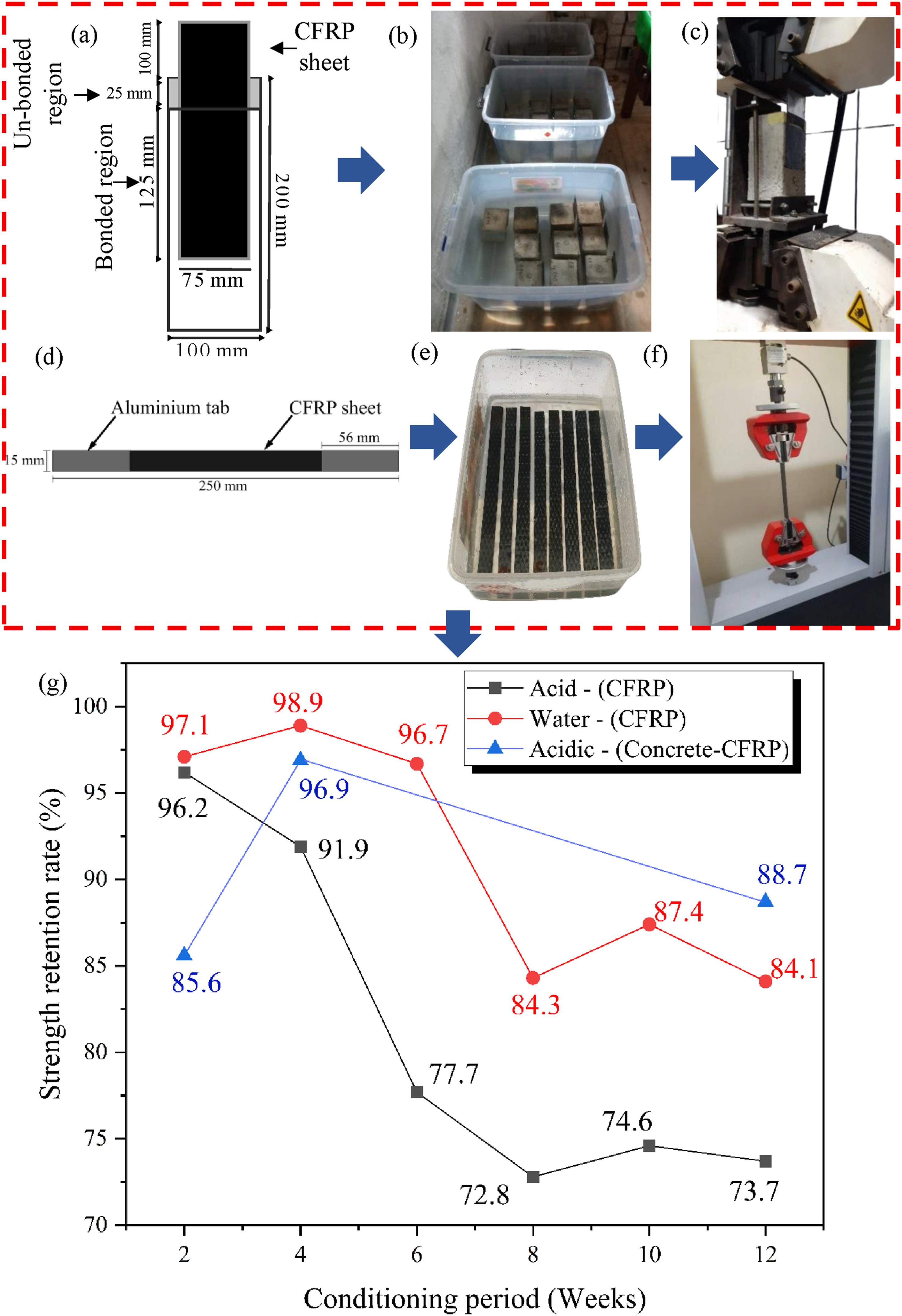
Based on these data, an environmental reduction factor of 0.80 was adopted in the CFRP strengthening design, to account for the potential long-term degradation of both the laminate and the bond interface. This value is more conservative than the 0.85 recommended by ACI 440.2R (2017), is consistent with the environment-specific factors reported by Thushanthan and Gamage (2025), and is in close agreement with Ji and Kim (2017), who proposed a reduction factor of 0.80 for CFRP following exposure to sulphuric acid. The factor was applied throughout the numerical assessment and strengthening design.
To extend the long-term performance of the CFRP system, the cured laminates were over-coated with a chemical-resistant waterproof coating, followed by a plaster protection layer, providing additional barriers against moisture and biogenic acid ingress. Elevated-temperature post-curing of the epoxy adhesive was also specified to enhance cross-linking and chemical resistance of the bond line, consistent with the recommendations of Bernaczyk et al. (2023) and Gamage et al. (2015, 2016).
It should be acknowledged that accelerated conditioning cannot reproduce every aspect of long-term field exposure, particularly sustained structural loading, cyclic stress fluctuations, microbial activity at the laminate surface, and progressive ageing of the protective coatings. Nevertheless, the experimental evidence above provides direct quantitative support for the residual tensile and bond performance of the CFRP system under severe aqueous and acidic conditioning and substantiates the use of the adopted reduction factors in the design. Long-term in-service monitoring will provide further verification over the design life of the rehabilitated structure.
Crack repair
The slab deflections had produced cracking on both the upper and lower surfaces of the roof slab [Figure 10(a)]. These cracks required repair prior to CFRP application, both to prevent further water ingress and reinforcement corrosion and to re-establish the structural continuity of the substrate, which is essential for effective force transfer into the CFRP laminate. All cracks of 0.3 mm width or greater were selected for repair. (a) Cross sectional view of a crack on the slab (b) epoxy injection peg insertion into the crack (c) injection of epoxy into the crack and filling the crack path.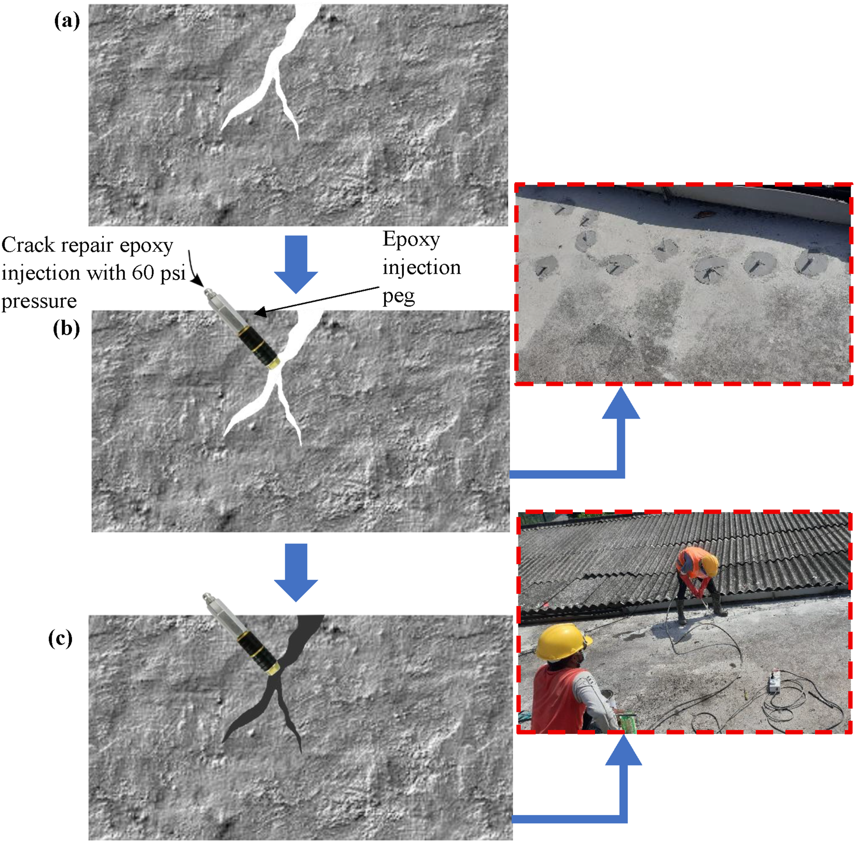
Repair was carried out by pressure-injected epoxy, selected for its ability to restore both watertightness and structural continuity across the cracked region. Specialised injection pegs (or ports) were installed along each crack at approximately 160 mm spacing [Figure 10(a)]. Each peg was configured so that one end could be connected to the injection gun nozzle while the other was inserted into the crack to provide a sealed pathway for resin flow. The pegs were temporarily anchored using a fast-curing surface sealant, which was also applied to the crack faces between adjacent pegs to prevent resin escape during injection.
A low-viscosity, two-component crack-repair epoxy was then injected through the pegs at approximately 60 psi (∼0.4 MPa), beginning at the lowest peg and progressing upwards to ensure complete penetration and filling of the crack profile to its terminus [Figure 10(b) and (c)]. After sufficient cure, the surface sealant and any residual cured epoxy were removed by mechanical grinding to restore a smooth, clean substrate suitable for CFRP application.
Epoxy injection was selected over cementitious grouting or surface sealing based on its superior performance in restoring structural integrity. Cementitious grouts are generally unsuitable for narrow cracks (less than ∼0.5 mm) owing to their inability to penetrate fine apertures and are prone to drying shrinkage that can result in incomplete bond and reopening of the repaired crack. Surface sealants, while effective in limiting water ingress, do not re-establish monolithic behaviour and cannot transfer tensile or shear stresses across the crack faces. Epoxy injection, by contrast, both prevents further ingress of aggressive agents and restores tensile and shear transfer capacity across the cracked plane; a critical requirement, since the CFRP laminate relies on the integrity of the underlying substrate for effective stress transfer.
Reconstruction of the deteriorated column
The failed column was partially demolished, with the upper 1.0 m and lower 1.5 m of the original column section retained in place [Figure 11(a) and (b)]. The retained sections were selected to preserve sound, undamaged concrete at the column-slab and column-base connections, while allowing the deteriorated central portion which contained the failed construction joint and the severely corroded reinforcement to be removed entirely. The remaining sections were inspected to confirm that the surrounding concrete was visibly sound and that the embedded reinforcement was free from significant corrosion new reinforcement bars were then chemically anchored into these remaining sections. The anchoring process was carried out in accordance with the manufacturer’s specifications, including the recommended drilling depths and installation procedures. Following the anchoring of reinforcement, the column was reconstructed using sulphate resistant cement concrete to enhance durability against the aggressive environmental conditions present in the equalisation tank (Figure 11(c)). (a) Partially demolished column (b) column reconstruction process (c) reconstructed column.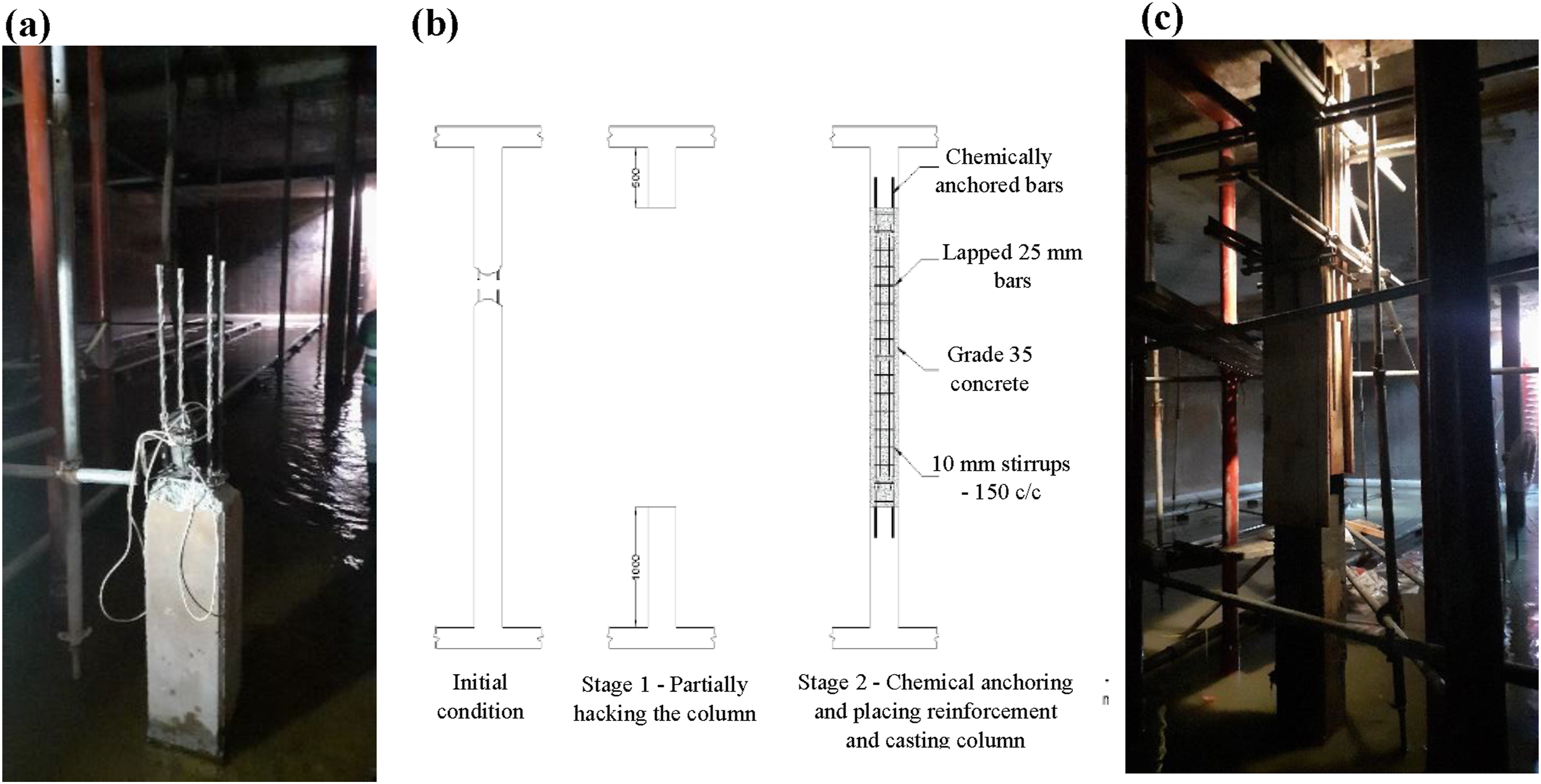
Surface preparation
Preliminary surface treatment
The effectiveness of an externally bonded CFRP system depends primarily on the load-transfer mechanism between the composite and the structural substrate, which is governed by the strength of the bonded interface (Mosallam et al., 2012). While the cohesive strength of the adhesive is important, adhesion to the concrete substrate is equally decisive: inadequate preparation can lead to premature debonding, delamination, or both, with serious consequences for the strengthened element. Surface preparation was therefore carried out in three stages: initial substrate preparation, moisture control during the preparation period, and final cleaning immediately prior to CFRP application.
Substrate preparation requires the removal of weak surface material, laitance, and foreign particles, and the achievement of a clean, sound, roughened surface for effective adhesive bonding. Available methods include sandblasting, high-pressure water jetting, mechanical chipping, and grinding, each producing a different surface profile classified by the Concrete Surface Profile (CSP) system of ICRI Guideline No. 310.2R-13 (2013). Ariyachandra et al. (2017) showed that abrasive-blasted surfaces produce significantly improved flexural performance in CFRP-strengthened beams compared with ground or smooth surfaces, owing to higher roughness and exposed coarse aggregate. A schematic comparison of grinding and abrasive blasting is shown in Figure 12(a). (a) Schematic diagram of surface preparation using grinding and sandblasting (b) concrete surface before preparation (c) concrete surface after preparation using high pressure water jet (d) plastic rollers are rolled over freshly adhered CFRP fabrics (e) sand sprinkled on CFRP sheets to increase the surface roughness (f-1) column circumferentially wrapped by CFRP sheet for axial strengthening (f-2) waterproofing coating applied on the CFRP wrap (f-3) column after the application of 25 mm thick plaster (g) CFRP strengthened beam after water proofinfing and plastering (h) CFRP strengthened slab after waterproofing and plastering (i) 75 mm elevated water barrier constructed around the perimeter of CFRP strengthening slab panels to prevent the rain water accumulation in deflected areas (j) final view of the equalisation tank top after grade 20 concrete fill for aesthetic appearance.
In the present rehabilitation, FRP application was required both within the confined internal spaces of the tank, accessible only through small openings, and on exposed external areas of the roof. Conventional sandblasting raised practical and safety concerns under these conditions, particularly regarding airborne dust and abrasive particle scattering within a densely industrialised zone. High-pressure water jetting was therefore adopted, producing a comparable profile through water-jet impact while avoiding the dust and ventilation issues associated with abrasive blasting. The water jetting was applied at approximately 50–57 MPa (7250–8250 psi), maintained until the coarse aggregate became visibly exposed across the prepared surface, confirming sufficient removal of the surface laitance and weak cement paste [Figure 12(b) and (c)]. The resulting surface profile was visually consistent with CSP-7 in accordance with ICRI Guideline No. 310.2R (2013).
The rounding of all sharp corner edges on rectangular columns and beams was an essential preparatory step where wrap-type FRP confinement or U-wrapping was to be applied. Sharp edges act as stress concentrators along the laminate, causing localised fiber rupture at strain levels well below the nominal tensile strain capacity of the composite, particularly under transverse compressive contact pressure during confinement (dos Santos et al., 2013). Rounded edges, by contrast, distribute confinement pressure more uniformly around the perimeter and substantially improve strengthening efficiency. All corner edges to be wrapped were therefore rounded to a radius of approximately 50 mm using an electric concrete grinder, substantially exceeding the 13 mm minimum specified by ACI 440.2R (2017) for FRP confinement applications.
Surface moisture removal inside the tank
Substrate moisture is a critical consideration in externally bonded FRP applications, as residual moisture on the prepared surface inhibits adhesive penetration into the surface micropores and significantly reduces the mechanical interlock that governs the long-term bond strength. ACI 440.2R requires the substrate to be visibly dry and recommends that the substrate temperature be maintained at no less than 3°C above the local dew point throughout the application of the adhesive system to prevent recondensation.
External surfaces of the tank roof were exposed to direct sunlight and natural ventilation and were allowed to dry naturally without the need for active intervention. Within Compartment A, however, the conditions were considerably more demanding: although the compartment had been drained, the geometry of the outlet configuration caused residual standing water (up to approximately 50 mm in depth) to remain at the base of the compartment, and the high humidity of the enclosed environment combined with cyclic external temperatures produced repeated condensation cycles on the soffits of the slab and beams.
To mitigate this issue, two complementary measures were implemented within the compartment. High power floodlights were installed on elevated platforms and directed towards the soffits of the slab and beams, providing localised radiant heating to accelerate surface drying and to maintain substrate temperatures above the local dew point. In parallel, industrial exhaust fans were positioned at the compartment access openings to provide continuous extraction ventilation, reducing the relative humidity of the headspace, inhibiting recondensation on the prepared surfaces, and ensuring compliance with confined-space safety procedures during preparation and adhesive application. The supervising engineer and consultant inspected the soffit condition at approximately one-hour intervals during the drying process, with substrate dryness assessed visually based on the absence of moisture sheen, surface darkening, or condensation droplets.
Final surface preparation
Final surface preparation was carried out immediately prior to the application of the CFRP system to ensure optimum bond performance. Following the water jetting, edge rounding, and drying operations described above, any residual loose particles, dust, or grinding debris were removed by uniform application of clean, dry compressed air across the prepared bonding surface. The substrate was then wiped with isopropyl alcohol applied via clean lint-free cloths, removing fine dust, surface grease, and any other organic contaminants that could have impaired adhesion. The alcohol was allowed to evaporate completely before subsequent application steps.
For internal soffit surfaces in particular, an additional dry-wipe step was carried out using a clean, lint-free cloth immediately before primer application, to remove any thin residual film of moisture that might have formed since the visual inspection but could not be reliably detected by eye alone. Following completion of these moisture-control and cleaning measures, primer and CFRP application were carried out without further delay to minimise the period during which recontamination or recondensation could occur on the prepared surface.
Preparation of epoxy resin and CFRP fabric
The impregnating epoxy was a two-component, ambient-cure structural system comprising a base resin (Part A) and a hardener (Part B). The components were measured by weight in the manufacturer-specified ratio of 2:1 (A: B) and mixed using a low-speed paddle mixer until a uniform colour and consistency were achieved, with no visible streaking. Mixing was carried out in batches sized to allow complete application within the manufacturer’s pot life at the prevailing site temperature, ensuring adequate workability and bond performance throughout the application period.
The prepared resin was applied to the substrate using brushes or short-nap rollers to produce a continuous wet film. CFRP fabric, pre-cut to the required size, was then laid onto the resin-coated substrate with the principal fiber direction aligned to the design tensile-stress direction, and a second resin layer applied to the exposed face to complete the wet lay-up. This technique is one of the most widely adopted approaches in CFRP strengthening, owing to its low cost and suitability for in-situ works on members of varying geometry (Thushanthan et al., 2022). Ribbed plastic rollers were then passed firmly over the surface in the direction of the fibers to expel entrapped air and ensure complete fabric impregnation [Figure 12(d)], with particular attention to wrapped corners and laminate overlap zones where air entrapment is most likely. Coarse silica sand was sprinkled lightly over the wet outer epoxy while it remained tacky, providing surface roughness for mechanical interlock with the subsequent protective coating layers [Figure 12(e)]. Application proceeded continuously to avoid the formation of cold joints within the laminate.
For the roof slab, pre-impregnated CFRP laminates were used in place of wet lay-up fabrics. The slab surface offered sufficient working space for laminate placement, and pre-impregnated laminates provide more uniform resin distribution, better quality control, and higher tensile efficiency than site-impregnated fabrics. Their use ensured consistent strengthening performance in the critical regions of the roof slab while complementing the wet lay-up method applied elsewhere.
Elevated temperature curing
Elevated temperature post-curing of structural epoxy adhesives is an established method for increasing the glass transition temperature (Tg) of the cured polymer, thereby enhancing the long-term mechanical and bond performance of the CFRP system under elevated service temperatures and aggressive environmental conditions (Chandrathilaka et al., 2019b). Gamage et al. (2016, 2017) reported that an increased Tg improves the long-term durability of the concrete-CFRP bond under conditions of sustained humidity, cyclic temperature, and combined chemical and mechanical loading; all of which are present in the operational environment of the equalisation tank. Chandrathilaka et al. (2019a) further demonstrated that the Tg of a typical structural epoxy increased by approximately 10% when the curing temperature was raised from 30°C to 55°C, and by a further 10%–20% when the curing duration was extended from 1 hour to 4 hours.
Based on these findings, elevated temperature curing was applied in this project using floodlights. Immediately after adhesion of CFRP sheets to the substrate, the high-power floodlights previously used for substrate drying (Section 6.5.2) were repositioned and directed at the bonded CFRP surfaces to provide localised radiant heating. The surface temperature of the cured laminate was monitored continuously using a non-contact infrared thermometer at multiple representative locations and was maintained within a target range of 55–65°C for a sustained period of approximately 1 hour. Following the elevated-temperature exposure, the laminates were allowed to cool gradually to ambient temperature without forced cooling.
CFRP strengthening
Inside the tank
The effectiveness of the CFRP strengthening system depends strongly on the continuity of load transfer across the concrete-CFRP interface. In critical regions such as slab-beam junctions, wall-slab intersections, and beam ends, CFRP strips were not terminated within zones of high bending moment, high shear demand, or active cracking, as such termination promotes stress concentration and premature debonding. Each CFRP element was therefore extended beyond the critical region by an adequate development length, with sufficient overlap between adjacent strips and end anchorage provided by U-shaped wraps where required. The elevated-temperature post-curing described in Section 6.6.3 further enhanced bond reliability through the increase in adhesive Tg. Although direct energy-absorption measurements were not undertaken in this field study, the detailing adopted contributes to improved crack control, load redistribution, and structural continuity, enhancing the overall robustness and durability of the rehabilitated system.
Outside the tank
Prior to CFRP installation, the site engineer and consultant inspected each external slab area to confirm the absence of visible surface moisture. Floodlights were not required for these areas, as natural sunlight was considered sufficient under the prevailing site conditions in Sri Lanka. Immediately before CFRP application, the prepared surfaces were wiped with a dry cloth to remove any residual moisture or loose particles.
Following CFRP installation, plastic sheets were placed over the strengthened areas to protect them from rainfall during the curing period, and the temporary mortar barriers prevented runoff from adjacent areas entering the strengthened zones. After the required curing period, a waterproofing coating was applied over the CFRP-strengthened areas, and the top surfaces of the slabs were subsequently overlaid with a Grade 20 waterproof concrete topping to restore a level surface profile and provide additional protection against water ingress [Figure 12(j)].
Load transfer across critical interfaces
In the rehabilitated structure, load transfer occurs across two principal interface types. At the concrete-CFRP interface, tensile force transfer is governed by adhesive bonding and mechanical interlock, both of which are enhanced by the rough CSP-7 surface profile, the deep aggregate exposure achieved during water jetting, and the final cleaning and drying steps that improved adhesive penetration into the substrate. At CFRP strip terminations, U-shaped wraps provide supplementary anchorage and reduce the risk of premature debonding under tensile demand.
At the structural-system level, load transfer between slabs, beams, walls, and columns depends on the continuity of reinforcement, the integrity of the concrete, and the presence of an uninterrupted vertical load path. The original failure of the construction joint had interrupted this load path, producing the stress redistribution, crack propagation, and slab deflection described in Section 5. The rehabilitation strategy comprising column reconstruction, crack injection, CFRP strengthening, and protective finishing, restored the continuity of all these mechanisms, returning the structural system to a state in which its intended load paths and resistance functions can operate effectively.
Conclusion and recommendation
This paper has presented an integrated investigation and rehabilitation of an industrial wastewater treatment plant equalisation tank in Sri Lanka, in which a single defective construction joint had triggered progressive structural deterioration and near-collapse of an interior column after only 15 years of service. The principal conclusions arising from the work are summarised below.
A localised construction defect in this case, an inadequately executed construction joint in one of the interior columns was sufficient to initiate a cascade of deterioration leading to column failure and severe slab deflection (span/32, far exceeding the BS 8110 serviceability limit of span/250). This finding underlines the disproportionate consequences of seemingly minor workmanship deficiencies in liquid-retaining structures and reinforces the importance of strict adherence to construction-joint detailing standards (BS EN 1992-3, ACI 350), including continuous water stops, elastomeric sealants, and rigorous quality control during construction.
SEM-EDX analysis confirmed the presence of ettringite formations indicative of sulphate-induced microstructural deterioration in the cover concrete of the soffits, driven by biogenic sulphuric acid attack within the headspace of the tank. While existing standards such as ACI 201.2R and BS EN 206 provide guidance on cement type and water-cement ratio for liquid-phase sulphate exposure, this study confirms that vapour-phase sulphate attack within confined wastewater environments can be at least as severe. Chemical-resistant protective coatings should therefore be specified on critical reinforced concrete members exposed to such conditions (Salgado et al., 2020; Vitiello et al., 2016).
The success of CFRP rehabilitation in this aggressive environment depended on three critical conditions: the soundness of the underlying concrete substrate (achieved through targeted demolition and reconstruction of deteriorated zones); the durability of the concrete-CFRP bond interface (enhanced by surface preparation to CSP-7, the application of protective coatings, and elevated-temperature post-curing at 55–65°C to increase the cured adhesive Tg); and the appropriate selection and sequencing of complementary repair measures.
Future research should address three areas: long-term in-service monitoring of CFRP rehabilitations within operational wastewater environments to generate field durability data presently absent from the literature; the development of explicit design guidelines for vapour-phase sulphate exposure in confined service environments; and the optimisation of hybrid retrofitting strategies combining CFRP with complementary protective and monitoring systems. The methodology and techniques reported here are broadly applicable to similar reinforced concrete systems operating in chemically aggressive or confined environments.
Supplemental material
Supplemental Material - CFRP based rehabilitation of a near collapse reinforced concrete wastewater structure under aggressive exposure: Failure mechanism and structural implications
Supplemental Material for CFRP based rehabilitation of a near collapse reinforced concrete wastewater structure under aggressive exposure: Failure mechanism and structural implications by Thushanthan Kannan, Kumari Gamage, and Fernando Vimukthi in Advances in Structural Engineering.
Footnotes
Acknowledgement
The authors gratefully acknowledge the valuable and continuous support of Mr Sugath Paranawidanage [Director (Technical Services), Board of Investment of Sri Lanka], Mr Ananda Gunawadena [Director (SEPZ), Board of Investment of Sri Lanka], Mr Maheen Ranasinghe [Assistant Director (Engineering Services), Board of Investment of Sri Lanka], and Mr H.A.T.T. Hettiarachchi (Resident Engineer, Seethawaka Water Board). The authors also wish to thank the staff of Unic Consultancy, SEPZ, and Airow Solutions for their assistance during the project. The authors further acknowledge the valuable support provided by Mrs. Srishangavi Thushanthan, Rajarata University, Sri Lanka, during the preparation of the manuscript.
Author contributions
Funding
The authors disclosed receipt of the following financial support for the research, authorship, and/or publication of this article: The authors express their appreciation for the financial support from the Senate Research Council of University of Moratuwa.
Declaration of conflicting interests
The authors declared no potential conflicts of interest with respect to the research, authorship, and/or publication of this article.
Data Availability Statement
The data that support the findings of this study are available from the corresponding author upon reasonable request.
Supplemental material
Supplemental material for this article is available online.
References
Supplementary Material
Please find the following supplemental material available below.
For Open Access articles published under a Creative Commons License, all supplemental material carries the same license as the article it is associated with.
For non-Open Access articles published, all supplemental material carries a non-exclusive license, and permission requests for re-use of supplemental material or any part of supplemental material shall be sent directly to the copyright owner as specified in the copyright notice associated with the article.