






Abstract
The increasing demand for architectural aesthetics has led to a rise in landmark structures featuring distinctive and geometrically complex concrete members. These free-form shapes present substantial challenges for conventional metal or timber formworks, which are costly and labor-intensive. To address these limitations, this study proposes an integrated fabrication workflow combining 3D printing and automatic fiber winding technologies to produce permanent, free-form fiber reinforced polymer (FRP) formworks for concrete structures. The workflow mainly involves: (1) 3D printing a polymer mandrel with the complex geometry; (2) automatically winding resin-impregnated fibers onto the mandrel with a computer-controlled system; (3) casting concrete into the FRP formwork to form the hybrid structural member. A case study involving the fabrication and testing of four variable-section prototype members confirmed the feasibility and efficiency of the proposed method. The case study provides a proof-of-concept route for typical free-form concrete structural members and the proposed technique offers an advantageous alternative to traditional formwork systems.
• A novel integrated fabrication methodology for permanent FRP formwork for free-form concrete members is proposed; • The proposed method is based on 3D printing and automatic filament winding technologies; • A case study of four variable-section prototype members confirms the feasibility and efficiency of the proposed method; • The prototype column and beam elements possessed great load-carrying capacity and ductility.Highlights
Introduction
With the rapid expansion of mega-cities and growing pursuit of unique architectural expression, the demand for free-form concrete structures (Figure 1) has significantly increased in recent years. While these landmark projects enhance aesthetic appeal, the incorporation of elements with irregular geometries presents considerable challenges in both design and construction (Darbandi et al., 2010; Huang and Li, 2011; Saraçaoğlu and Uzun, 2020; Soltani and Mohri, 2014; Šapalas et al., 2005). In particular, the fabrication and installation of free-form concrete members (Figure 2) via conventional construction methods are inherently difficult, especially when stringent requirements for geometric accuracy and tight construction schedules are imposed (Ryu and Kim, 2012). Representative free-form concrete buildings over the world. Special-shaped concrete members.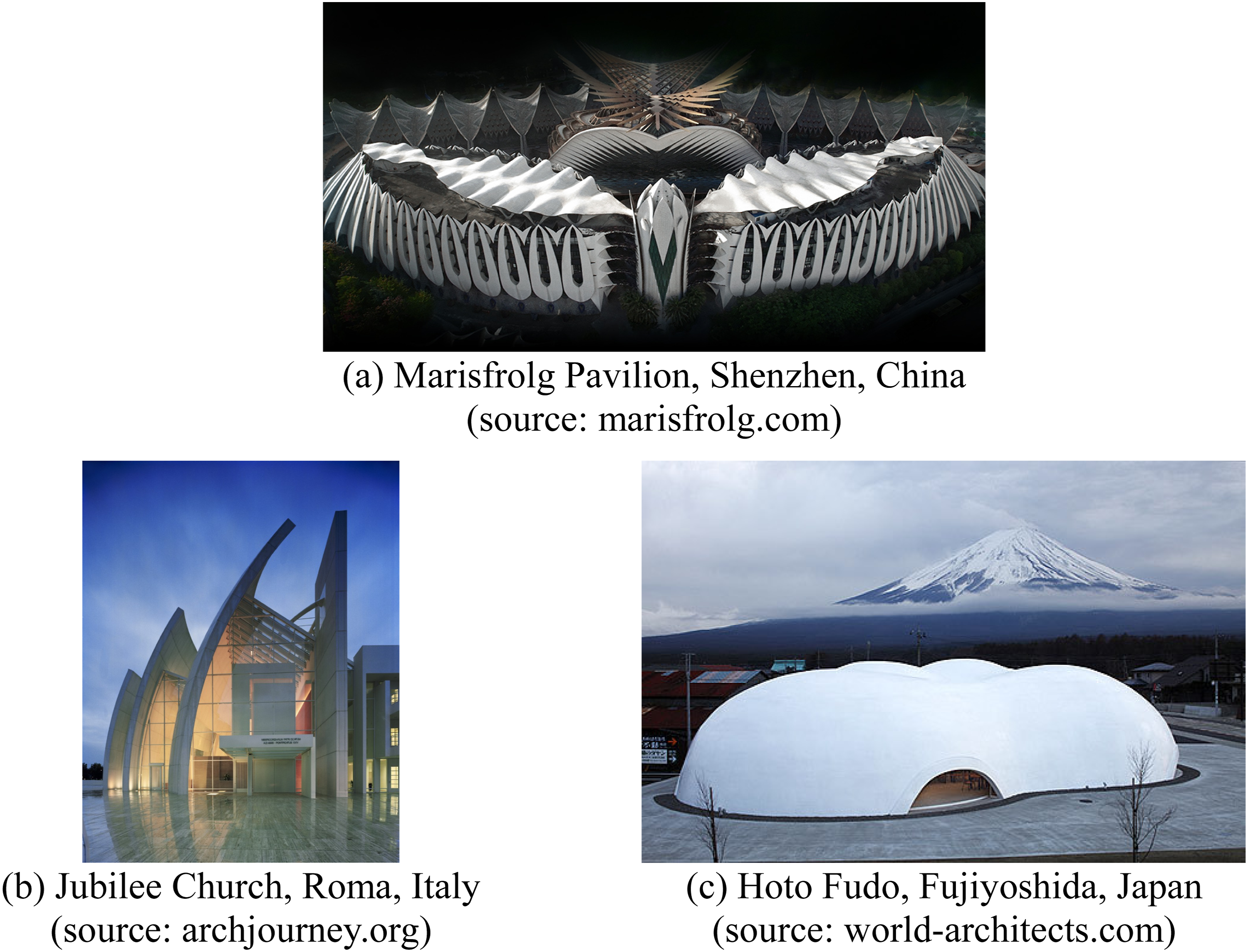
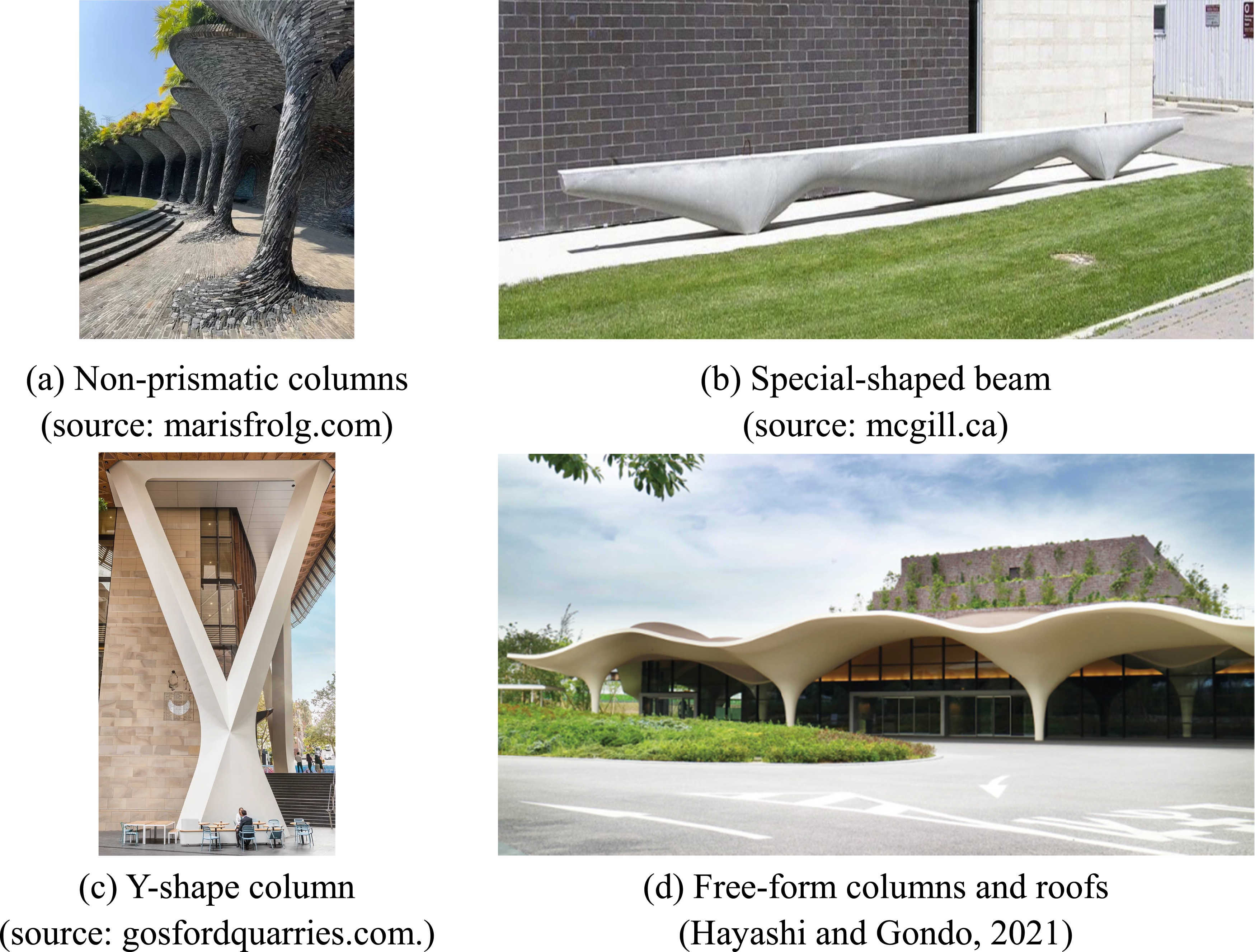
For these free-form concrete members, formwork fabrication has become the critical bottleneck in construction. The cost and complexity associated with formwork production frequently outweigh those of the concrete or reinforcement, typically accounting for 40∼60% of total construction costs in free-form projects, and potentially up to 80% for highly intricate geometries (Hyun et al., 2018; Liebringshausen et al., 2023). While conventional systems, including timber, concrete, steel and polymer formworks, are effective for standard structures (Li et al., 2022; Nilimaa et al., 2023; Pawar et al., 2018; Peng et al., 2023; Zhu et al., 2024, 2026), their applicability deteriorates sharply when extended to free-form geometries. This difficulty is rooted in the following fundamental aspects. Most importantly, free-form members often feature continuously varying curvatures and non-uniform cross-sections. Achieving the required geometric precision using conventional timber or steel formworks is exceptionally demanding. While CNC (computer numerical control) machining can improve accuracy, it requires stringent equipment conditions and significantly increases fabrication costs. Besides, the presence of complex concave and convex surfaces along the member makes formwork removal (demolding) highly problematic, and often infeasible. Furthermore, the creation of unique geometries from standard raw materials, such as steel plates, requires extensive subtractive processes, which inevitably results in substantial offcuts, material waste, and high energy consumption, undermining the project’s sustainability. Collectively, these drawbacks converge on the same prohibitive outcome: excessive costs and intensive labor requirements, which act as the primary barrier for the application of conventional formworks in free-form concrete structures. Therefore, the development of an efficient, high-performance, and sustainable formwork fabrication system is urgently needed to support the continued growth of architecturally complex concrete construction in modern cities.
Recent studies indicate that 3D-printed polymer formworks offer a compelling strategy to overcome the issues in free-form concrete structures, mitigating the high cost, material waste, and geometric inflexibility of conventional timber or steel formworks. For instance, Burger et al. (2020) developed the “Eggshell” process, which combines thin, robotically extruded thermoplastic shells with concrete casting to produce free-form concrete columns (Flatt, 2020). Similarly, other researchers (Huber et al., 2023; Leschok and Dillenburger, 2019) successfully fabricated ribbed reinforced concrete slabs using 3D-printed polymer formworks integrated with finite element (FE) analysis, achieving a reduction of approximately 40% in concrete volume compared with solid slabs while maintaining validated structural performance. Despite the advances in geometric complexity offered by 3D printing, pure polymer formworks face significant mechanical weaknesses when compared with their conventional counterparts. Typical polymers exhibit low tensile strengths (ranging from 6 to 85 MPa) and low elastic moduli (typically 0.1 to 6.5 GPa). These poor properties make the formworks susceptible to buckling or even fracturing when subjected to substantial hydrostatic pressures exerted during concrete casting (Zuo et al., 2022). Short fibers have been introduced into polymers to suppress warping during printing and to enhance creep resistance during service (Tezel et al., 2019; Yan et al., 2021). However, such modifications offer only limited improvement to the mechanical performance of polymers (typically less than 20%). Consequently, the overall load-bearing capacity of printed pure polymer formworks remains insufficient for direct use in load-bearing structural applications (Gray Iv et al., 1998).
Alongside the application of 3D-printed polymer formworks, direct 3D printing of concrete has emerged as another promising additive-manufacturing technique to create complex and formwork-free geometries (Ding et al., 2025; Shi et al., 2026; Zhang et al., 2019). This technique eliminates temporary formworks, improves material efficiency and reduces on-site labor and construction time (Lyu et al., 2021; Xiao et al., 2021). However, its application in complex free-form structures faces several technical limitations. Because of the low tensile capacity and pronounced anisotropy of 3D-printed concrete due to weak layer-to-layer bonding, the printed formwork faces difficulty in withstanding the significant lateral tensile stresses induced by fresh concrete during casting. Furthermore, the layer-by-layer deposition process inevitably yields a relatively rough surface finish and poor dimensional accuracy, often requiring cost-intensive post-processing that diminishes initial time and cost savings. More importantly, the achievable geometric complexity is still restricted, as the range of printable shapes and overhangs is limited by the fresh-state rheology of concrete (Jipa and Dillenburger, 2022).
To address the aforementioned challenges of existing formworks for free-form concrete structures, this study proposes an integrated fabrication workflow combining 3D printing and automatic fiber winding technologies. This workflow is designed to produce free-form fiber reinforced polymer (FRP) formworks that serve as permanent and load-bearing structural components for complex concrete elements. The full utilization of 3D printing simplifies fabrication and enhances geometric precision, leading to substantial cost reduction and minimal material waste. Furthermore, the superior corrosion resistance of FRP can enhance the durability and thus the service life of the resulting hybrid FRP-concrete structures. Although 3D-printed polymer formworks, filament winding, and hybrid FRP-concrete structures have each been studied previously, their coordinated use for constructing free-form concrete structures remains unexplored. The following section details the proposed integrated fabrication method for these free-form FRP formworks and their resulting hybrid members.
Proposed integrated fabrication method of free-form formwork and concrete members
Overview
The integrated fabrication workflow for producing the free-form FRP formwork and the resulting hybrid FRP-concrete member is illustrated in Figure 3, which comprises three primary and sequential procedures: (1) 3D Printing of Polymer Mandrel: A polymer mandrel (formwork core) is fabricated using a 3D printer and a specific thermoplastic material. Printing parameters are carefully selected to ensure a balance among dimensional accuracy, surface quality and thermal stability required for the subsequent winding and curing processes. (2) Precision Filament Winding: Resin-impregnated fibers (such as glass, carbon or basalt fibers) are automatically wound around the polymer mandrel. This filament winding process is controlled via a programmed path under controlled tension and deposition speed. The resin is subsequently cured to form a continuous and bonded FRP layer integrated with the polymer core. (3) Concrete Casting: Any required internal reinforcement is placed prior to concrete casting; fresh concrete is then cast into the stay-in-place FRP formwork, consolidated, and cured, yielding a structural member in which the printed polymer mandrel, the cured concrete and the FRP formwork interact as a hybrid member. During casting, the deformation of the thin-walled formwork should be precisely controlled to meet the shape requirement of the final structural member. Where appropriate, temporary external supports or positioning fixtures, stiffening ribs in critical regions, and/or local wall thickness increasing could be adopted. Workflow of the fabrication procedure: (a) 3D printing of polymer core; (b) filament winding; (c) concrete casting.
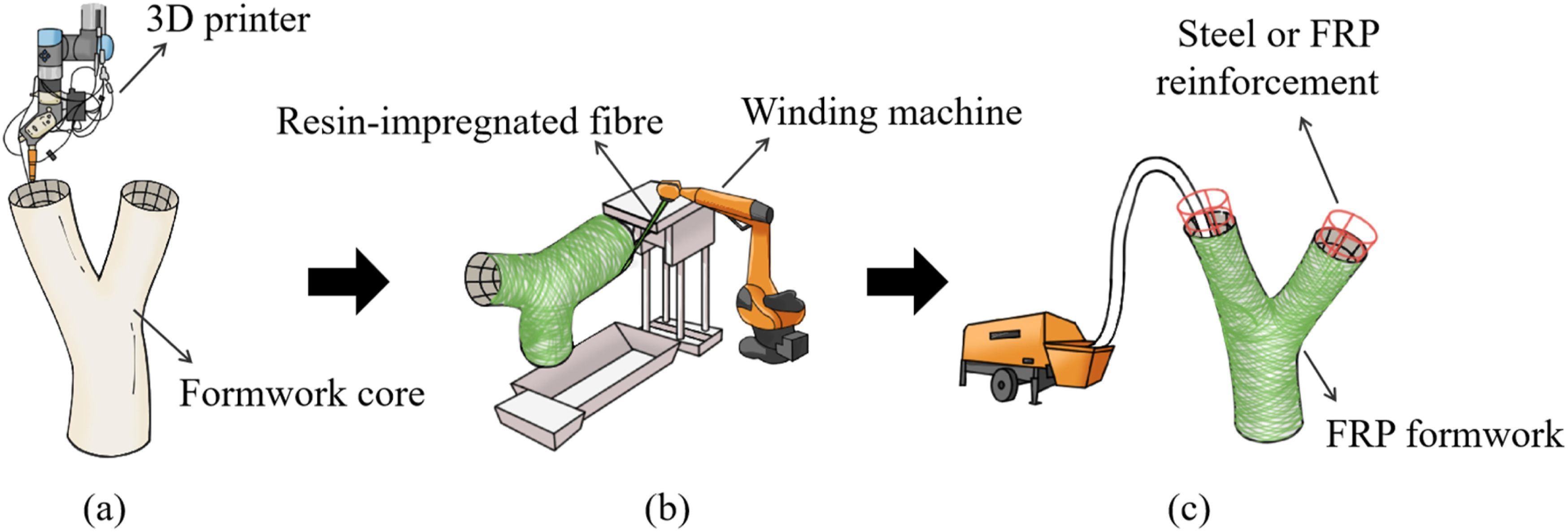
The technical details of the first two procedures, i.e., 3D printing and filament winding, will be introduced in the following subsections, detailing the step-by-step workflows and the selection criteria for fabrication methods and materials. It is important to note that for practical large-scale structures, the free-form formwork must be fabricated in segments that are subsequently connected to form the complete structural envelope. The integrated fabrication method proposed here (i.e., 3D printing and filament winding) remains fully applicable for producing these individual segments, which are partitioned during the digital design phase based on printer build volume, winding-machine workspace, transportation logistics, and site assembly constraints. This segmental approach also ensures high-quality fabrication and rigorous quality control for each component before delivery. However, to ensure the overall mechanical performance and durability of the final structure, appropriate connection technologies and design methodologies must be developed. On-site assembly typically involves aligning segments using positioning keys, sleeves, or mechanical connectors, followed by bonding, sealing, and localized reinforcement through external FRP overlap layers or secondary winding to ensure structural continuity. These joints are required to provide geometric alignment, efficient force transfer, and watertightness during concrete casting. It is also important to note that these joints represent critical structural regions characterized by potential stiffness discontinuities, stress concentrations, and inevitable interruption of fiber continuity. Consequently, to guarantee the overall mechanical performance and durability of the full-scale structure, dedicated experimental investigations are essential before transitioning from laboratory prototypes to full-scale engineering implementation.
3D Printing of polymer mandrel
General
The fabrication of the polymer mandrel (formwork core) via 3D printing is divided into the following two primary steps: (1) Geometric Modeling and Digital Preparation: The three-dimensional (3D) model of the formwork core is first generated using computer-aided design (CAD) software, such as AutoCAD or SolidWorks. This geometric model is then processed into a slicing model within the chosen slicing software. (2) Parameter definition and Printing Execution: Key printing parameters are defined based on the required dimensional accuracy and surface finish. These parameters typically include the selection of the thermoplastic printing material, infill rate, printing speed, nozzle and bed temperatures, and temporary support settings. Finally, the printing process is executed on a 3D printer to fabricate the polymer mandrel.
Printing methods
Recent comparative studies show that while some cutting-edge 3D printing techniques, such as Stereolithography (SLA) and Digital Light Processing (DLP), yield very high resolution and excellent surface finish, they suffer from drawbacks including brittleness, higher material cost, complex post-processing and limited environmental durability. In contrast, Fused Deposition Modeling (FDM), which utilizes thermoplastic filaments made of Polylactic Acid (PLA), Acrylonitrile Butadiene Styrene (ABS), or Polycarbonate (PC), offers distinct practical advantages (Abbasi et al., 2025; Hozdić, 2024). FDM systems provide larger build volumes, a broader range of material options, and significantly lower equipment and operational costs. Moreover, FDM-printed components exhibit superior durability under various environmental exposure. Nevertheless, it is important to note that the deposition rates of conventional filament-extrusion FDM (typically 20∼200 g/h) may still restrict its suitability for real-scale structural applications in construction. In recent years, pellet-extrusion additive manufacturing, a variant of FDM, has been developed as a large-scale alternative (Luo and Zhang, 2023; Pagés-Llobet et al., 2023). By utilizing polymer pellets or granules instead of filaments, this technology achieves significantly higher extrusion rates (ranging from 10 to 100 kg/h), offering greater potential for architectural and structural engineering applications (Hao et al., 2021).
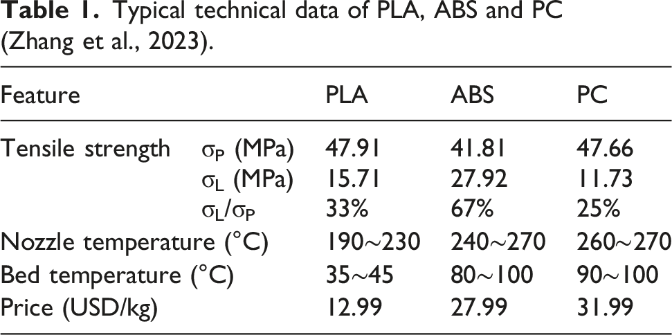
Printing materials
Typical technical data of PLA, ABS and PC (Zhang et al., 2023).
Filament winding of fibers
General
The geometric complexity inherent to the free-form formwork necessitates a winding process significantly more complex than conventional methods used for regular components (e.g., standard tubes or pressure vessels). Consequently, the proposed filament winding operation requires a high degree of precision and control. This process is structured into three main steps, which collectively translate the specialized structural design requirements into a precise computer program for execution by the automatic winding machine: (1) Design of Fiber Winding Paths: the process initiates with the generation of precise fiber winding paths and thickness parameters, which are based on optimized fiber angles, thicknesses, and densities across different regions of the hybrid member; such optimization may rely on analyzing the internal stress flows of the hybrid member derived from a reliable structural analysis or FE model. (2) Simulation and Computer Programming: the optimized winding paths and thicknesses are defined and simulated within a CAD/CAM system (Computer-Aided Design/Manufacturing); key winding parameters are computed and translated into a precise G-code program; during simulation, influencing factors such as surface friction, winding angle, and winding speed are carefully modeled to ensure the fibers adhere accurately and tightly to the mandrel surface. (3) Execution of Automatic Winding: the 3D-printed polymer mandrel is securely mounted onto a winding machine with a multi-axis winding function or a multi-degree of freedom industrial robot arm, and the programmed G-code is then executed to carry out the automatic filament winding of resin-impregnated fibers.
Winding methods
Automatic filament winding is a Computer Numerical Control (CNC) process that coordinates mandrel rotation, carriage translation, payout eye translation and rotation to precisely place continuous fibers at prescribed angles and speeds under controlled tension, typically using multi-axis machines and pre-designed toolpaths (Andrianov et al., 2022). Compared with manual winding or hand layup, which is serviceable for regular shapes such as round or square tubes, free-form formwork demands significantly tighter tolerances on fiber placement uniformity, winding angle and deposition rate. Automatic filament winding meets this requirement by providing precise path planning and repeatable execution, which effectively reduces operator-induced angle drift, overlaps, and gaps on curved geometries (Błachut et al., 2023; Chen et al., 2023a). Beyond conventional CNC winders, the proposed process could readily integrate with robotic arms to provide six-degree-of-freedom motion. This versatility enables nonstandard winding strategies, enabling consistent fiber placement on highly complex free-form formworks (Dambrosio et al., 2019). When coupled with vision modules for in-process sensing, this technology evolves into intelligent filament winding which can adapt trajectories and speeds in real time to maintain winding quality across highly curved surfaces (Wu et al., 2022). This capability is essential for the reliable fabrication of structurally optimized free-form formworks.
Winding fiber materials
The selection of fiber materials for automatic filament winding is primarily guided by a required balance of cost-effectiveness, processability, and durability. Among the available fibers, glass fibers are a preferred choice for stay-in-place formworks in construction. Glass fiber tows are flexible and tolerant of tension fluctuations, which is crucial for achieving tight radii and variable-angle paths with minimum fiber breakage. Glass fibers also achieve rapid and complete resin impregnation when mixed with common resins, providing a wide and field-friendly process window (Hsiao and Daniel, 1996). The resulting glass FRP (GFRP) delivers relatively low cost per unit tensile stiffness. Mechanically, it exhibits high failure strain and good damage tolerance, which are vital characteristics for ensuring ductile confinement activation in concrete members. Besides, GFRP is electrically insulating and durable in marine environments, enhancing the service life of the hybrid structures (Bank, 2006). Compared with GFRP, carbon FRP (CFRP) is significantly costlier and its electrical conductivity poses a galvanic corrosion risk when in contact with steel components. Aramid FRP (AFRP) is expensive, highly sensitive to UV degradation, and generally weak in compression. Basalt FRP (BFRP) is currently less standardized and its crucial long-term durability in corrosive marine environments remains inconclusive due to a scarcity of supporting empirical data (Fiore et al., 2015). Consequently, glass fibers are considered as the preferred winding material for the free-form stay-in-place formworks proposed in the present study.
Advantages of the proposed hybrid structure and its fabrication method
The proposed integrated FRP formwork system and its concrete hybrid structures offer the following advantages over both conventional formwork systems and existing construction approaches of free-form concrete structures: (1) Enhanced Fabrication Efficiency and Cost Reduction: the integrated fabrication workflow fully leverages the benefits of 3D printing for complex geometries, leading to a substantial reduction in project costs; besides, the polymer core is designed as a permanent mandrel for fiber winding, eliminating the need of demolding. This avoids the difficult demolding challenges typically associated with complex filament wound FRP products. (2) Superior Structural Performance and Material Efficiency: the permanent FRP formwork possesses high mechanical performance, allowing it to function as a load-bearing structural component that takes on part of the service load; this allows for the reduction or even elimination of internal steel or FRP reinforcement, which dramatically lowers both material and labor costs. (3) Enhanced Durability: The superior corrosion and UV resistance of the permanent FRP formwork significantly enhances the structure durability and service life, consequently reducing maintenance costs and lowering the life-cycle cost.
The proposed integrated FRP formwork system creates structural members that fall under the established category of FRP tube-confined concrete (FRP-CC) members (Dong et al., 2021; Fam and Rizkalla, 2001; Lin and Xiang, 2023). Such structural members leverage the well-documented benefits of FRP confinement, which effectively enhances both the strength and ductility of the concrete core, thus significantly improving the seismic performance and load-carrying capacity of the members (Lin et al., 2016; Lin and Teng, 2019; Teng et al., 2015, 2016). Crucially, the permanent FRP tube also provides a major durability benefit by acting as a barrier against environmental degradation. Different from conventional FRP-CC members, the proposed hybrid system incorporates a thin polymer layer between the FRP tube and the concrete core. Given its negligible thickness, this interfacial layer is not expected to alter the fundamental confinement mechanism of the outer FRP tube. However, for hybrid members with irregular cross-sections, the confinement is inherently non-uniform, departing significantly from the uniform confinement observed in regular circular cross-sections (Chen et al., 2021; Lin et al., 2020; Lin and Teng, 2020; Zeng et al., 2021; Zhu et al., 2020). This geometric irregularity underscores the strategic value of automatic filament winding, which allows for the tailoring of fiber paths, winding angles, and local layer thicknesses to match the local stress demands of irregular cross-sections.
For structures with fire-resistance requirements, external fire protection can readily be applied to meet design demands (GB 50608, 2020). Besides, since the FRP tube in an FRP-CC member generally carries load passively under general service conditions, the internal forces in the tube are typically small; this allows for the sacrifice of the FRP tube under fire exposure without significantly compromising the load-carrying capacity of the member (Teng et al., 2007). FRP-CC members, particularly those utilizing filament-wound FRP tubes, have been the subject of extensive research over the past few decades (Chen et al., 2023b, 2024; Huang et al., 2023; Jiang et al., 2023; Lin et al., 2024a, 2024b, 2025; Teng et al., 2007; Xie et al., 2023a, 2023b). This technology has successfully transitioned from laboratory study to practical application in major civil engineering projects, serving as essential components such as bridge girders, piers, or main arches (Chen et al., 2022; Lai, 2021). The current study extends this well-established concept by providing a digitally integrated fabrication route for producing free-form FRP confining tubes, thereby translating the proven structural and durability benefits of FRP-CC members to those with architecturally complex geometries.
It is worth noting that when the bonding between the FRP layer and the polymer mandrel is important (e.g., in beams where the FRP layer contributes significantly to the bending resistance), printed surface texture could be generated on the mandrel for mechanical interlocking between FRP layer/concrete and polymer mandrel. However, for contact critical cases (e.g., in columns where the fibers are arranged predominantly in the hoop direction to provide confinement to the inner concrete), interfacial bonding is not critical and thus no specific surface treatment is required for the polymer mandrel (Lin and Teng, 2017, 2019; Teng et al., 2002, 2016).
Case study: Variable-section columns and beams
To validate the feasibility of the proposed fabrication method, a proof-of-concept case study was conducted on four prototype column and beam members with variable cross-sections. As illustrated in Figure 4, the step-by-step fabrication process of each type of members was demonstrated and their structural performance under typical loading conditions was examined. PLA was used as the printing material to print the formwork core, and glass fibers were wound onto the printed core through automatic filament winding. Concrete was filled into the resulting FRP formworks and cured to form the prototype members. The successful fabrication and testing of these prototypes demonstrated the feasibility of the proposed method for the design and construction of free-form concrete structures, although more repeated specimens and parametric tests are still required for statistical validation in the future. Flowchart of design and fabrication of prototype members.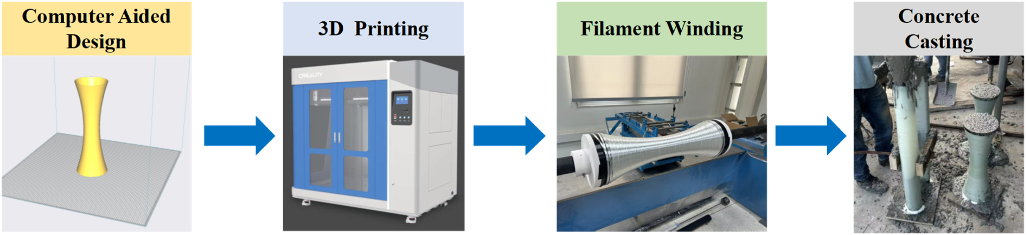
Design and fabrication
Geometry
Columns
Figure 5 shows the geometric dimensions of the variable-section polymer formwork core (mandrel) for the prototype columns in a three-dimensional view. The cross-section is circular at both the top (Cross-section T-T) and the bottom (Cross-section B-B), with an inner diameter of 200 mm and an outer diameter of 204 mm. At mid-height (Cross-section N-N), the section size reaches its minimum, with the inner and outer diameters being 100 mm and 104 mm, respectively. The change in the inner diameter along the height is defined by a quadratic curve. The wall thickness was held constant at 2 mm throughout the height; consequently, the outer profile is simply offset outward by 2 mm from the inner surface. Geometric dimensions of the formwork core for the prototype columns.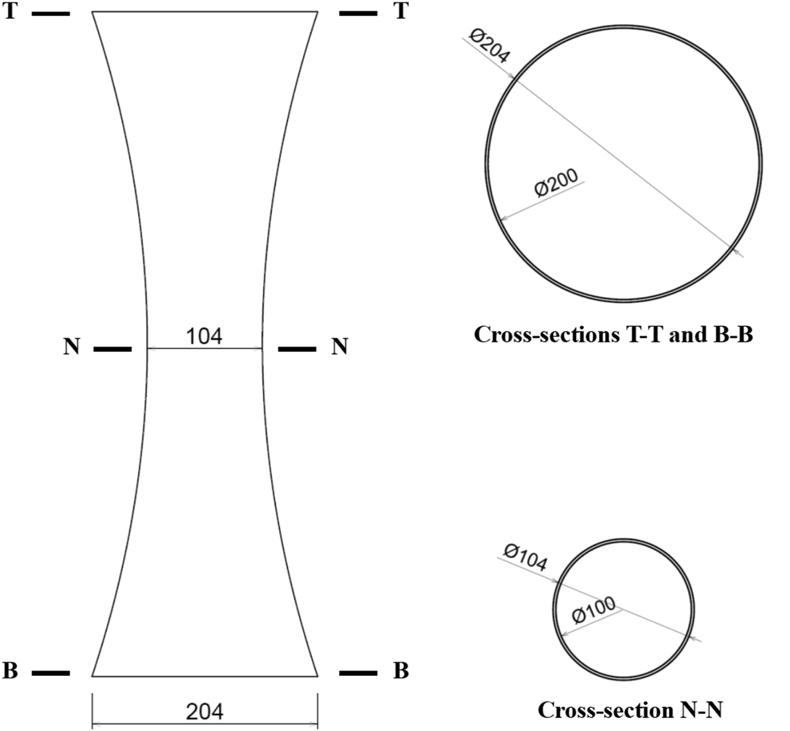
Beams
The geometric dimensions of the polymer formwork core for the prototype beams, featuring a continuously tapering height and transitioning profile, are presented in Figure 6. At mid-span (Cross-section M-M), the inner profile is a semi-ellipse with a major semi-axis of 100 mm and a minor semi-axis of 50 mm. The sharp top corners of the profile are rounded with fillets to mitigate stress concentrations in the FRP formwork. The 100-mm width and the 2-mm wall thickness of the formwork core are held constant along the beam span. The cross-section height tapers quadratically from its maximum at mid-span towards both ends (Cross-sections L-L and R-R). Concurrently, the cross-section transitions smoothly from the semi-ellipse at mid-span to a semi-circle profile at the beam ends, creating a geometrically complex member with continuous curvature. Geometric dimensions of the formwork core for the prototype beams.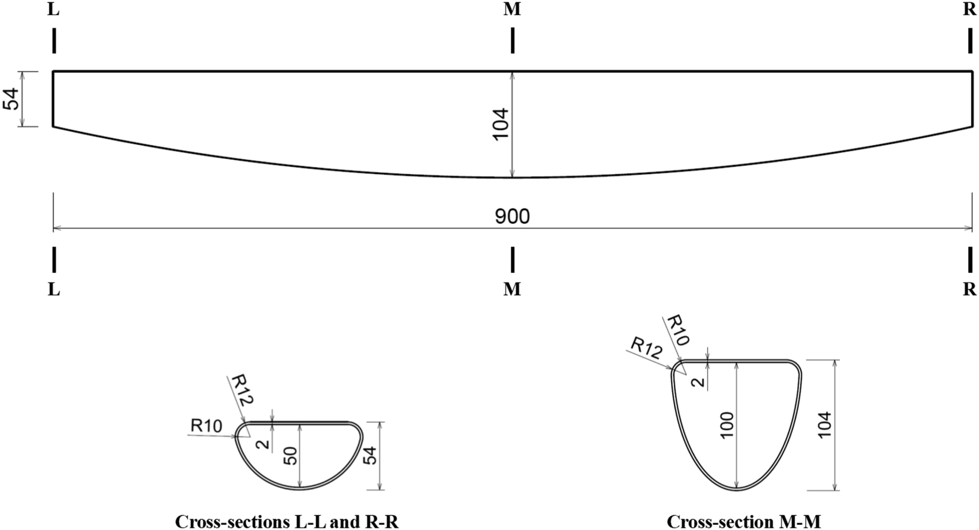
Materials
In the present case study, PLA was selected as the printing material due to its biodegradability, low warping tendency and excellent printability. Glass-fiber rovings were impregnated with epoxy resin and then wound around the formwork core to form the FRP layer. According to the manufacturer, the glass fibers possessed a tensile strength of 2580 MPa and a tensile modulus of 80.1 GPa with a single fiber diameter of 24 μm. Following the completion of the winding process and the curing of the formwork, fresh concrete was filled into the formwork. Four companion cylindrical concrete specimens (150 mm × 300 mm) were cast and cured for more than 28 days, which were then tested under uniaxial compression in accordance with ASTM C469/C469M-22 (2022) at a constant loading rate of 250 ± 50 kPa/s, yielding an average compressive strength of 35.2 MPa. For the prototype columns and beams, no internal steel or FRP reinforcement was utilized due to the relatively compact scale of the test specimens. As discussed previously, the proposed permanent FRP formwork system significantly mitigates the need for internal reinforcement by providing inherent structural resistance. Specifically, the fiber orientation, which is predominantly configured in the hoop direction, effectively substitutes for traditional transverse reinforcement, thereby substantially simplifying the reinforcement placement process. In applications where internal reinforcement is required, the placement process can be efficiently managed. Longitudinal bars can be pre-bent into the required geometry and inserted into the formwork perimeter. To ensure structural consistency, spacers or custom fixtures may be installed at discrete intervals to maintain a constant concrete cover and secure the relative positioning of the reinforcement. For highly complex geometries where bar alignment is challenging, perforated steel or wooden templates can be integrated at various cross-sections to guide and support the longitudinal bars. It should be noted that for large-scale structural members in practice, the modular nature of the formwork which is fabricated in segments and connected onsite significantly eases the installation of internal reinforcement, even in the most intricate free-form configurations.
3D printing of formwork cores
A commercial 3D printer (Creativity CR-1000) was employed for printing the polymer formwork cores of the four prototype members. The printer operated based on the FDM technology and supported a maximum build volume of 1000 × 1000 × 1200 mm. The FDM process involves extruding a molten polymer filament through a heated nozzle, depositing material layer by layer along a predefined toolpath derived from sliced 3D models (see Figure 7). To accommodate the thermal and mechanical characteristics of PLA using FDM, the primary printing parameters were carefully established: the nozzle temperature was maintained at 220°C, and the bed temperature at 40°C. The printing infill rate was set to 100% to ensure maximum structural integrity of the permanent core and to help control deformation under fresh-concrete lateral pressure. Necessary supporting conditions were readily set before the execution of printing to ensure the geometric fidelity of the overhangs. 3D models of variable-section prototype members.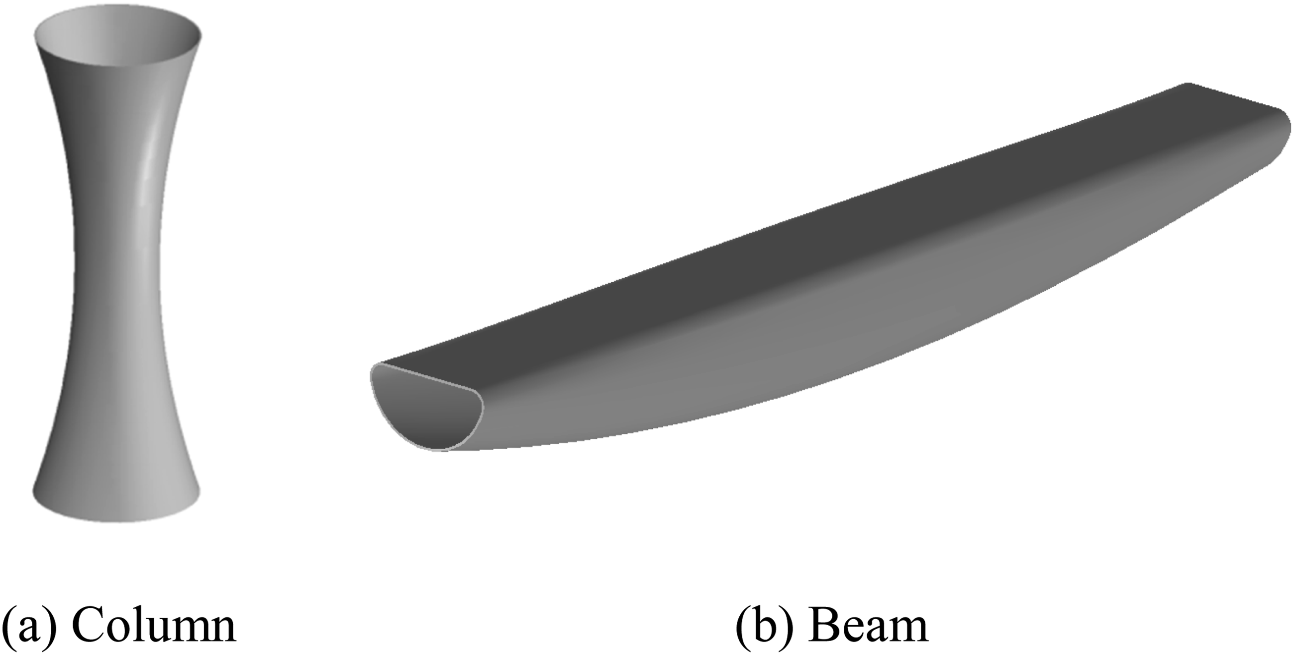
Filament winding of glass fibers
The prototype columns and beams were reinforced using distinct glass fiber winding patterns (see Figure 8) according to their dominant structural demands: circumferential winding was applied to the columns, while helical winding was used for the beams. For columns under axial compression, lateral expansion of the concrete core activates hoop tension in the FRP layer, making circumferential fibers efficient for providing lateral confinement. For beams under bending, helical winding provides both longitudinal and transverse stiffnesses, contributing to bending resistance and crack control. Appropriate winding paths should be designed, as the bonding quality between the glass fibers and the formwork core is strongly influenced by the winding sequences. Once the optimal winding path is confirmed, it is transformed into a G-code program, allowing for precise and repeatable implementation by the automatic winding machine. Upon completing the glass fiber winding processes, additional three layers of CFRP were wrapped around both ends of each member for preventing premature failure at the member ends during testing. Winding patterns of glass fibers.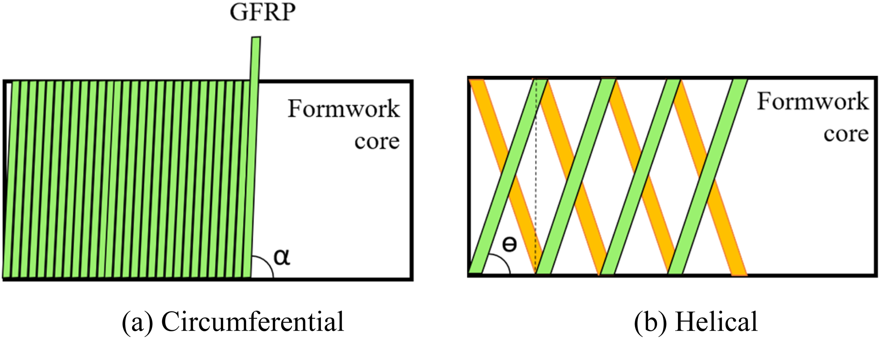
Circumferential winding for columns
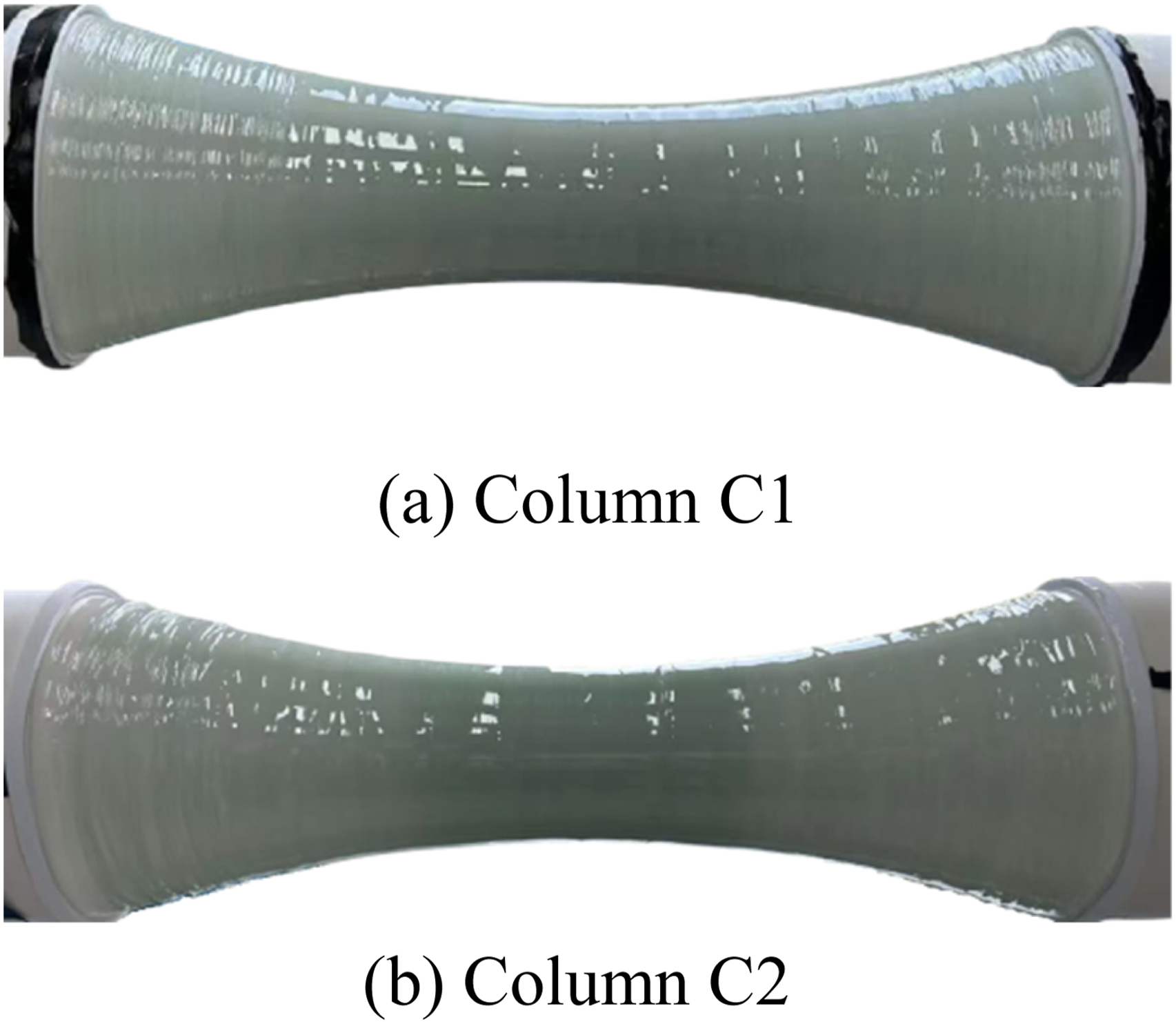
The winding sequences of Column C2 are shown in Figure 9 as an illustrative example. The process involved a total of six single-direction winding runs. The initial four runs established the base two layers of fibers. In each run, the winding commenced at the mid-height and moved towards one end. Upon reaching the end, the payout eye returned to the mid-height point and the path was repeated until the first four runs were completed. The final two runs were executed between the two trisection points to achieve the required two additional layers in the mid-height region. Column C1 followed only the initial four-run winding sequence for a uniform FRP layer throughout the height. The final fabricated formworks for both Columns C1 and C2 are shown in Figure 10. Winding sequences of Column C2. Column formworks with circumferential winding.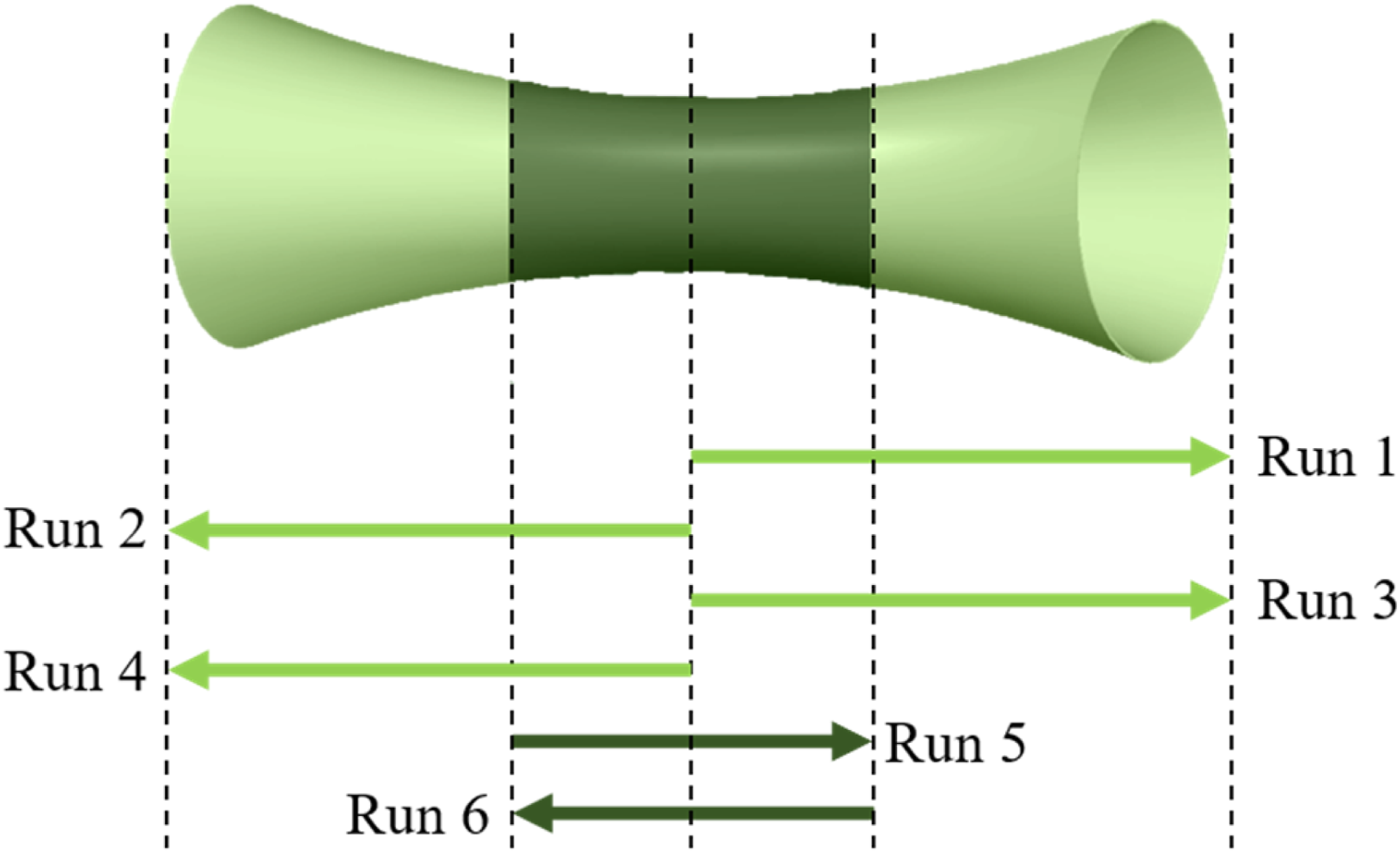
Helical winding for beams
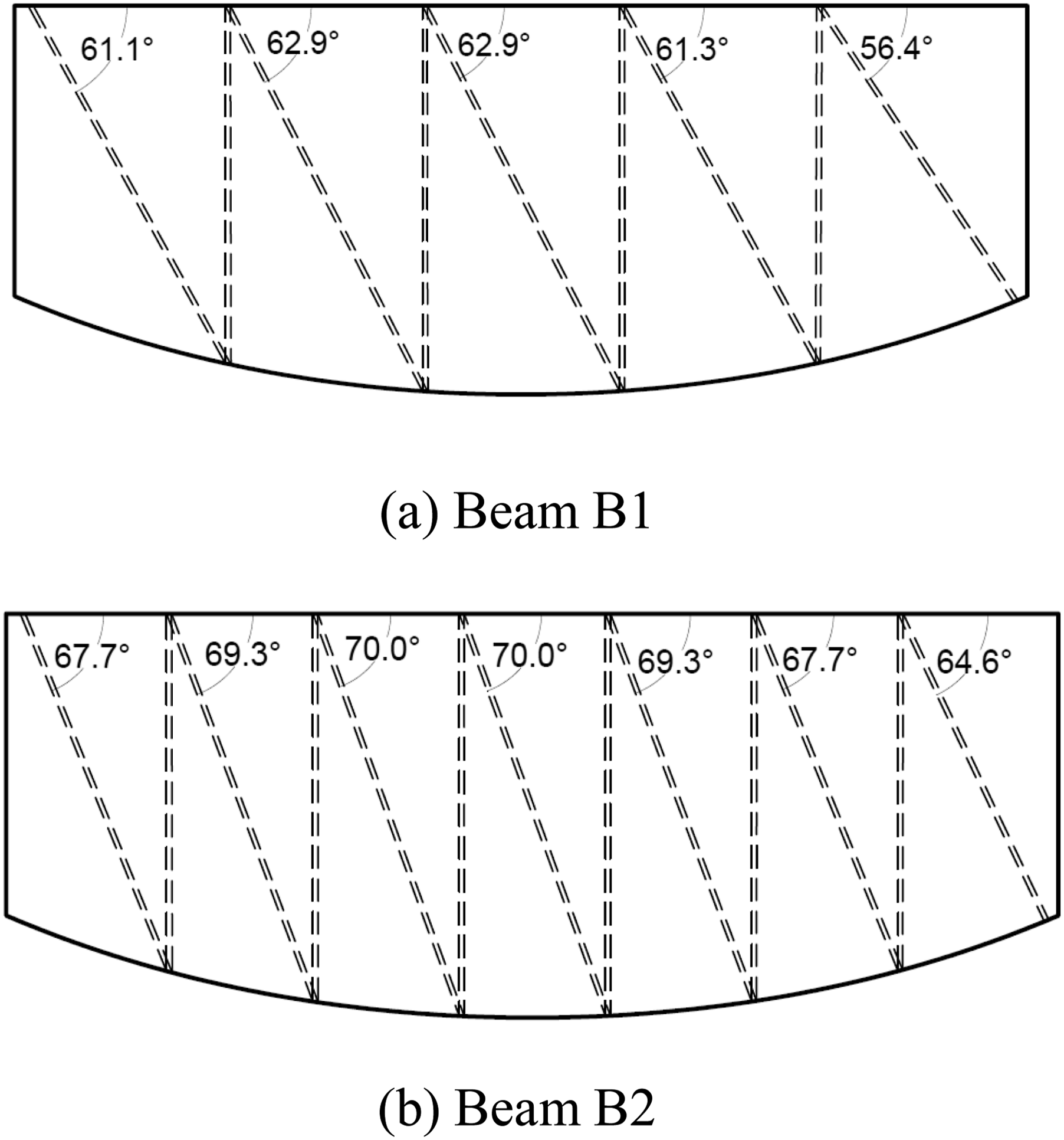
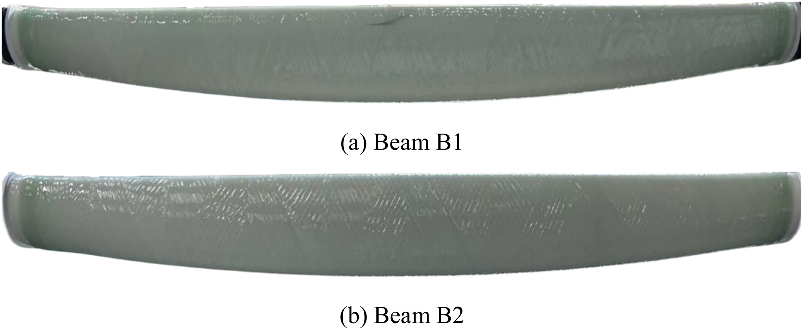
The prototype beams were helically wound with two layers of glass fibers. By utilizing relatively small winding angles (i.e., 64.6∼70.0° for Beam B1 and 56.4∼62.9° for Beam B2), the GFRP layers possessed significant stiffnesses in both the longitudinal and transverse directions, contributing to both the bending and shear resistances of the beams. To ensure full and uniform coverage of the entire span with glass fibers, the winding parameters were meticulously determined. Figure 11 illustrates the first half-run from left to right of the filament winding on the unfolded surfaces of Beams B1 and B2, showing seven and five cycles per winding run from left to right, respectively. Each full run of winding refers to the movement of the payout eye from one end to the other and back to the starting end. The key parameters for Beam B1 were established through the following steps, with the same methodology applied for Beam B2: (a) The perimeter of the largest cross-section (mid-span) was measured to be 345.6 mm. Given a nominal fiber filament width of 4 mm and the corresponding winding angle of 70.0°, the circumferential length covered by a single fiber filament was calculated as: 4/cos (70.0°) = 11.7 mm. (b) To achieve complete surface coverage, the required number of winding runs was estimated from the perimeter divided by the circumferential length covered by a single fiber filament: 345.6/11.7 ≈ 30.4. This value was rounded down to the nearest integer, resulting in 30 winding runs. (c) To provide adequate clearance for the fiber delivery mechanism at both ends of the beam, an additional full-cycle rotation was incorporated into the winding program. In this operation, the payout eye temporarily paused at the end position until the fiber filament completed its full-cycle rotation. The final fabricated formworks for the two beams are shown in Figure 12. The first half-run of winding filament on the unfolded surfaces of the beams. Beam formworks with helical winding.
Performance of columns under compression
Test set-up and instrumentations
The prototype columns were tested under unaxial compression to evaluate their structural performance. The test set-up is illustrated in Figure 13(a). The columns were placed on a 500-ton hydraulic servo-controlled testing machine. To ensure concentric loading and eliminate any initial eccentricities, thin gypsum layers were applied to both ends of the columns prior to testing. Before the formal loading, the columns were subjected to an axial strain rate of 20 µε/min until 10% of their estimated design load-carrying capacities were reached and then unloaded to zero. This cycle was repeated three times to effectively mitigate any initial eccentricity and stabilize the set-up. The load was then applied continuously on the columns with a rate of 10 µε/min from zero until the failure of the columns. The loading was terminated when the applied load dropped to 75% of the peak load. To capture the deformation characteristics of the columns, strain gauges (SGs) and linear variable displacement transducers (LVDTs) were installed as detailed in Figure 13(b). Four LVDTs were attached to the rigid loading plates between the columns to measure their overall shortenings. Eight SGs (four in the axial direction and four in the hoop direction) were mounted onto the outer surface of the GFRP tube at the column mid-height section to capture both the axial and hoop strains. Test set-up and instrumentations for columns under axial compression.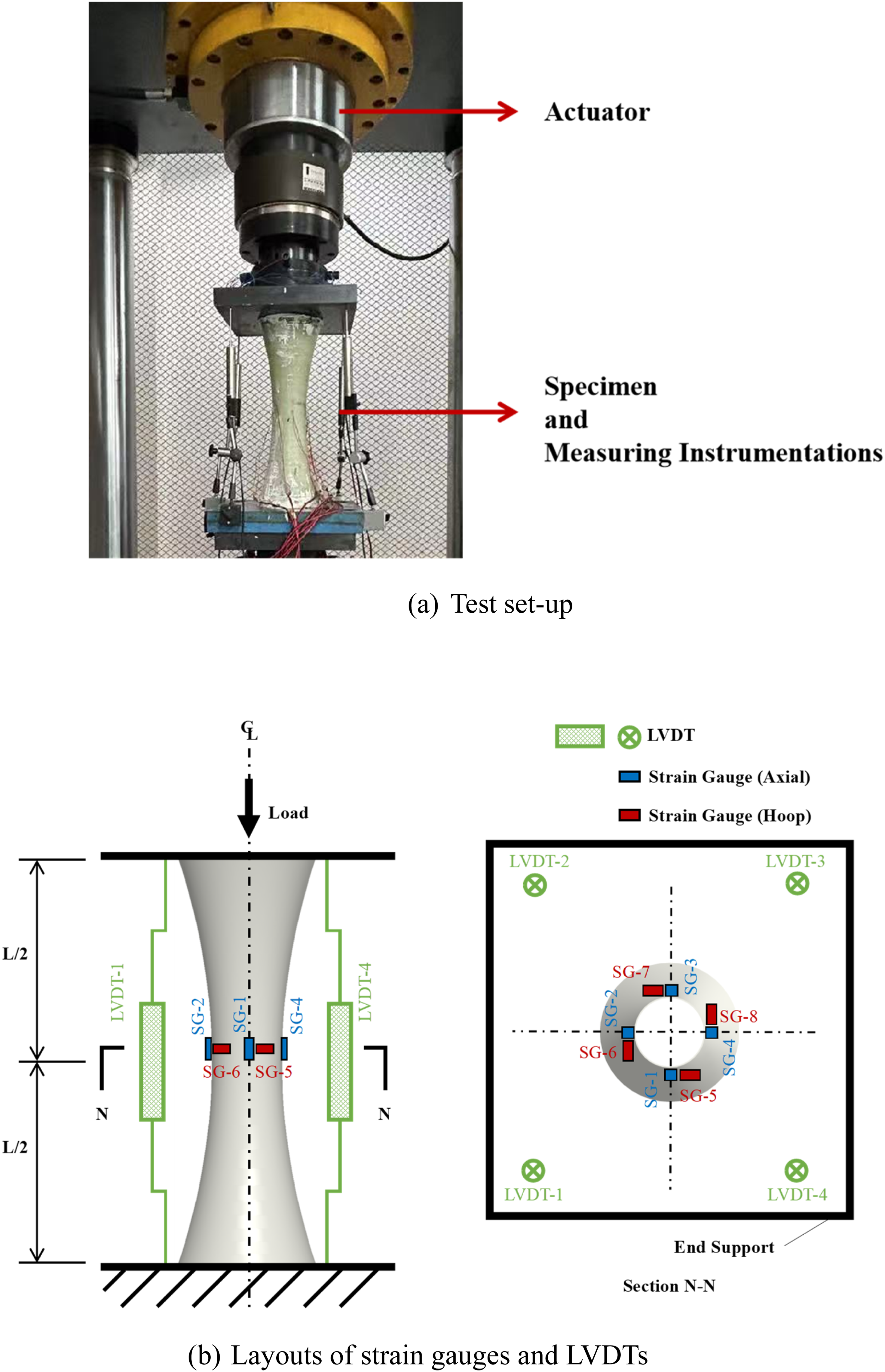
Test results
The axial load-displacement curves of Columns C1 and C2 are shown in Figure 14, where the axial displacements were averaged from the four LVDT readings. Both columns exhibited a characteristic bilinear response, which is typical for FRP-confined concrete columns. During the early loading stage, the two columns displayed similar behaviors but they began to diverge beyond approximately 350 kN. In the subsequent second stage, both columns continued to sustain an increasing load at a gradually decreasing rate, indicating the effective engagement of FRP confinement. Column C2 achieved a higher peak load of 766.1 kN at a displacement of 21.36 mm, whereas Column C1 peaked at a lower load of 533.6 kN with a corresponding displacement of 10.05 mm. The additional GFRP layers applied to the mid-height of Column C2 were highly effective, resulting in a 43.6% increase in load-carrying capacity compared to the uniformly confined Column C1. Note that the mid-height cross-section was the weakest due to the smallest cross-sectional area. This highlights the high potential for optimization of fiber arrangement in the hybrid structure for significantly enhanced performance where critical demands are present. Load-displacement curves of Columns C1 and C2.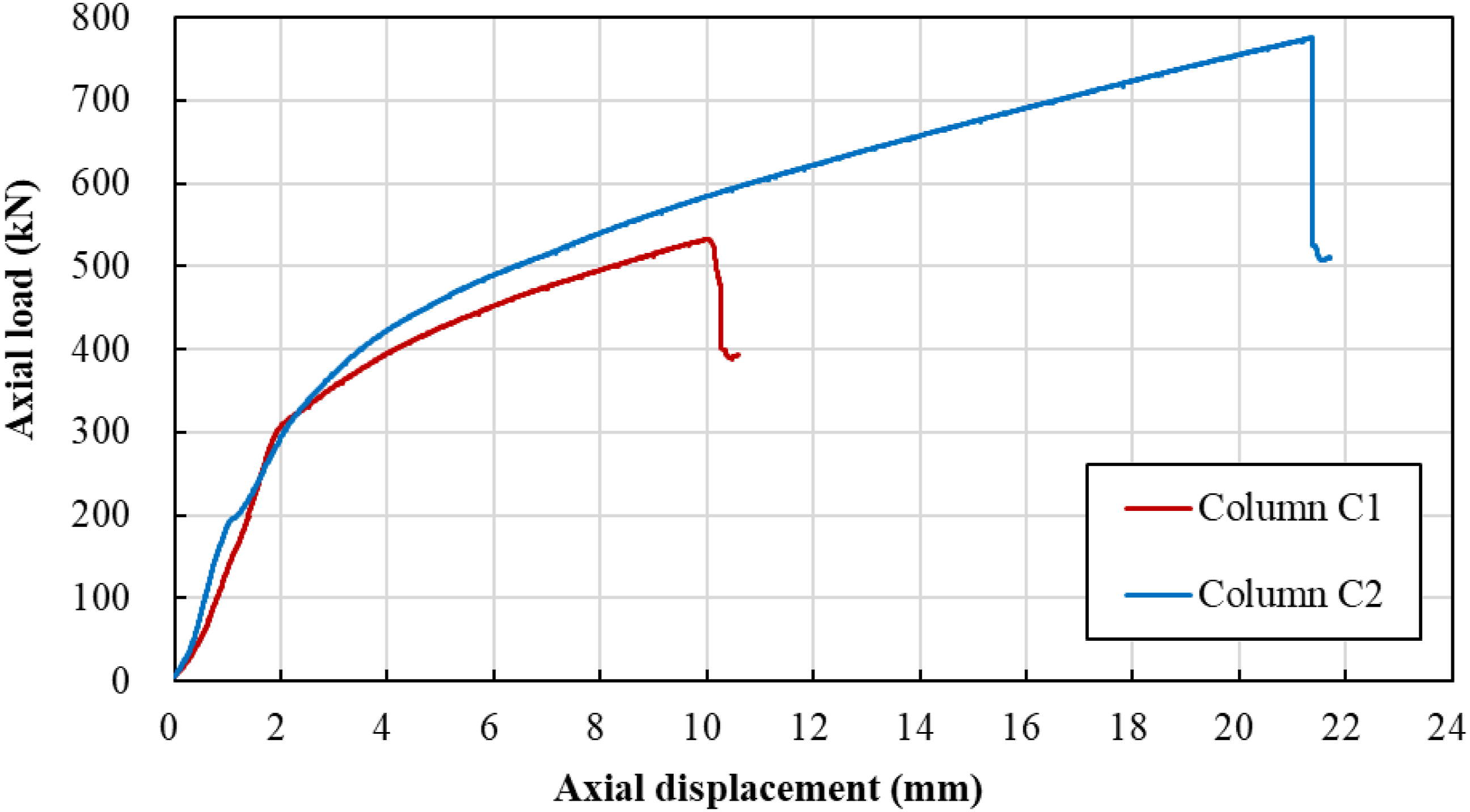
The failure modes shown in Figure 15 provide further insight into the mechanical differences between the two columns. While significant GFRP rupture was observed in both specimens, the locations of failure differed. Column C1, which had uniform two-layer GFRP confinement, experienced rupture precisely at the mid-height, where the ultimate axial strain at rupture reached 2.21% and ultimate FRP hoop strain reached 1.28%. Column C2, however, failed outside the thickened mid-height region. The additional GFRP layers successfully enhanced confinement in the mid-height region, delaying rupture and shifting the rupture failure to the less confined section. The mid-height section still exhibited comparable strain capacity, with the ultimate axial strain reaching 2.18% and the ultimate FRP hoop strain reaching 1.29%. This shift in failure location directly validates the efficacy of the proposed localized strengthening strategy in tailoring the confinement profile to meet specific structural demands. Failure modes of Columns C1 and C2 (units in mm).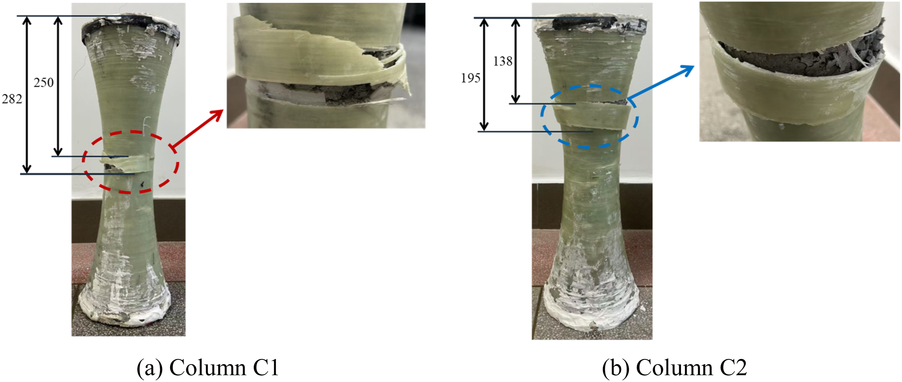
Performance of beams under bending
Test set-up and instrumentations
The prototype beams were tested under three-point bending to evaluate their flexural performance. The test set-up utilized a 300 kN capacity reaction frame, with load applied through a hydraulic actuator (see Figure 16(a)). Due to the curved bottom profile of the beams, a pair of customized concrete supports were designed to ensure stable placement on the pin/roller supports. Both ends of the beam were embedded in pre-cast concrete blocks with flat bearing surfaces. These blocks were then placed directly onto the pin and roller supports, which were securely fastened to the steel beam supports with steel bolts to prevent any translation or rotation during testing (Figure 16(a)). The compressive force from the actuator was transmitted via four steel rods to a square steel loading plate, applying the load to the mid-span of the beam. The test was conducted under manual control at a rate of approximately 0.7 mm/min. Test set-up and instrumentations for beams under bending.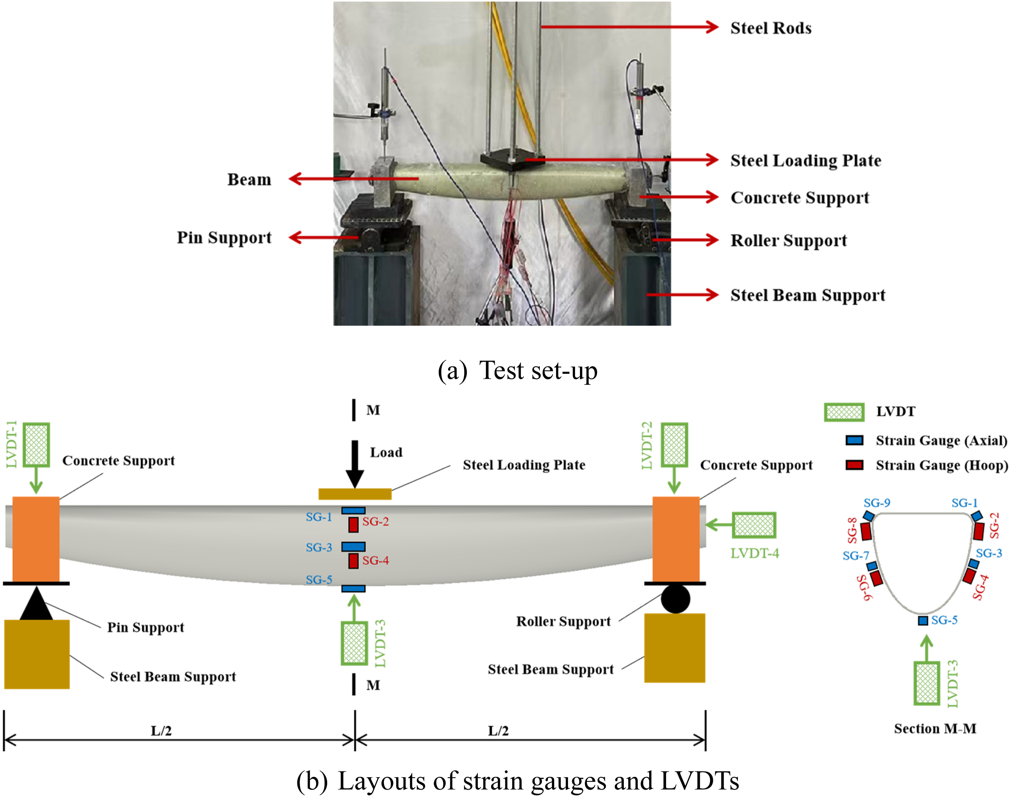
Similar to the column tests, SGs and LVDTs were positioned on the beams to capture comprehensive deformation data as detailed in Figure 16(b). Nine SGs were mounted on the outer surface of the mid-span cross-section to capture both axial and hoop strains. Three LVDTs were positioned at the mid-span and the two supports, respectively, to record vertical deflections, and one additional LVDT was installed near the roller support to measure horizontal displacements.
Test results
The load-deflection curves at the mid-span of the two beams are shown in Figure 17, which demonstrate very ductile behavior. Beam B2 exhibited both a higher peak load (8.1 kN) and a greater corresponding deflection compared with Beam B1 (6.0 kN). This performance differential was directly attributed to the smaller helical winding angles of Beam B2. The smaller winding angles allowed the GFRP layer to contribute more effectively to the axial tensile resistance of the hybrid section, thereby significantly enhancing the overall flexural capacity of the beam under bending. In both curves, several sudden load drops were observed, which were believed to be caused by the localized rupture of glass fibers and resin in the tension zone. Following each rupture event, the load quickly recovered as the remaining glass fibers continued to provide tensile resistance to the cross-sections. Load-deflection curves of Beams B1 and B2.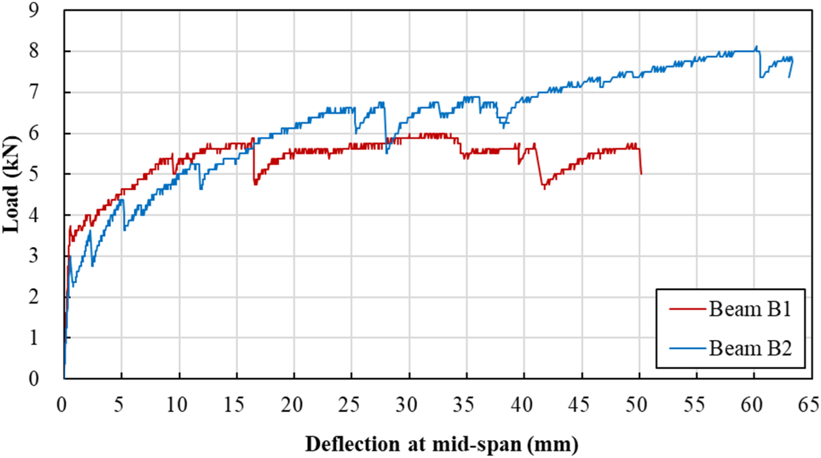
Further insights into the structural behavior are revealed by comparing the failure modes shown in Figure 18 and the corresponding strain data. Beam B1 failed through a localized rupture of the GFRP layer, which occurred slightly away from the geometric mid-span. Note that the vertical load from the actuator was applied onto the beams through the steel loading plate (Figure 16), which induced the maximum bending moment within a region near the mid-span. Consequently, the rupture occurred at the point where the combined effect of maximum bending moment and concentrated shear force resulted in the highest local stress concentration. At the mid-span section, Beam B1 recorded a maximum compressive axial strain of 0.52% and a maximum FRP hoop strain of 0.10%. On the other hand, Beam B2 reached a higher peak load and exhibited substantial plastic deformation without visible rupture of the GFRP layer throughout the loading process. This superior ductility is quantified by its significantly higher maximum strains, reaching 0.83% in axial strain and 0.52% in hoop strain at the mid-span section. The ability of Beam B2 to absorb more energy and reach higher strains without obvious rupture validates the efficacy of optimizing the winding angle for enhanced flexural performance, particularly in terms of ductility and flexural capacity. Failure modes of Beams B1 and B2.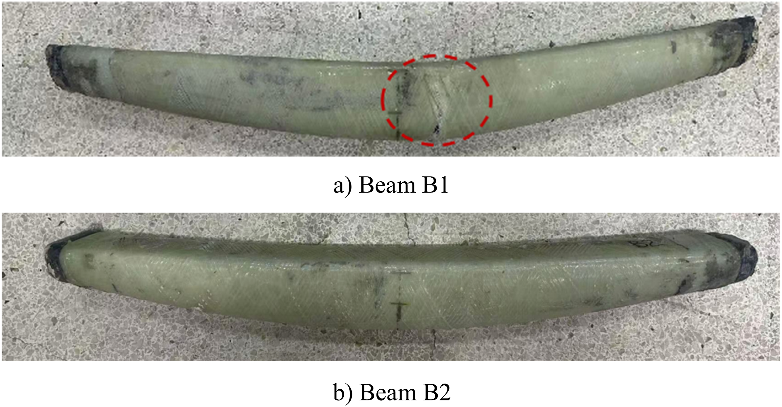
Conclusions
This study established an integrated fabrication method for fabricating permanent FRP formworks for free-form concrete members, combining FDM 3D printing and automatic filament winding technologies. The resulting FRP formworks can also function as load-bearing structural components and protective layers for the concrete members. A proof-of-concept case study involving four prototype concrete members with variable cross-sections was conducted to evaluate the feasibility of the integrated process and the resulting structural performance. The key conclusions are summarized as follows: (1) The integration of CAD modeling with 3D printing enables the rapid and precise fabrication of complex free-form polymer formwork cores. In the case study, formwork cores with continuously varying cross-sections were successfully printed using PLA, achieving a dimensional precision suitable for casting high-quality concrete surfaces. This efficient, minimal-waste process provides a substantially superior solution over conventional timber or metal formworks for geometrically complex construction. (2) The automatic filament winding process achieved accurate placement of fibers with controlled winding angles, ensuring strong adhesion to the polymer core surface. This process successfully fulfills the dual functions of providing confinement and corrosion protection for the formworks. For both columns and beams in the case study, winding paths were optimized based on the surface geometries and implemented using a G-code-driven winding machine, which confirmed the feasibility of this automated technique for complex formworks. (3) The GFRP formworks provided significant structural benefits to both the columns and beams in terms of compressive and bending performance. The case study showed that the column with additional GFRP layers at the mid-height (Column C2) exhibited a 43% increase in peak load and delayed FRP rupture compared to the uniformly confined column (Column C1). Similarly, the beam with a smaller winding angle (Beam B2) achieved a 35% higher peak load and greater ductility than its counterpart (Beam B1). These findings highlight the high potential for optimization of fiber arrangement in the proposed method to tailor performance and enhance capacity precisely where critical demands are present.
Overall, the proposed integrated fabrication method is demonstrated as an efficient, customizable and structurally promising approach. It extends the established benefits of FRP-confined concrete toward free-form and performance-driven concrete structures, offering significant potential for future civil engineering applications. However, extensive future studies on the proposed system, including optimization of fiber winding paths, segmental connections, reinforcement integration, interfacial behaviors among constituent materials, confinement mechanism, long-term durability, and design methods are required before reliable and full-scale engineering applications.
Footnotes

Author contributions
Funding
The authors disclosed receipt of the following financial support for the research, authorship, and/or publication of this article: The authors would like to acknowledge the financial support from Guangdong Basic and Applied Basic Research Foundation (Project No.: 2024A1515011268), Science, Technology and Innovation Commission of Shenzhen Municipality (Project No.: JCYJ20230807093414031), National Natural Science Foundation of China (Project No.: 52478256), Southern University of Science and Technology (Project No.: Y01316138), and The Hong Kong Polytechnic University (Project No.: G-SACP).
Declaration of conflicting interests
The authors declared no potential conflicts of interest with respect to the research, authorship, and/or publication of this article.