
Abstract
In this study, a novel refrigerant-heated radiator (RHR) was introduced and a computational fluid dynamics (CFD) model was developed to investigate the influence of RHR structure parameters on indoor thermal comfort under heating and cooling conditions. Results show that the heating capacity and thermal comfort are improved with the increase of length-to-height ratio, while the thermal comfort is infringed if the length-to-height ratio is too large in cooling conditions. The length-to-height ratio of the RHR with 2.22–3.71 is recommended to meet the thermal comfort requirements in heating and cooling conditions. Comparisons were made between the RHR and air conditioner on indoor thermal comfort, which indicates that the RHR has a better thermal comfort in heating conditions in terms of temperature field, velocity field and thermal comfort indices. Under cooling conditions, the air conditioner has lower temperature distribution and more uniform vertical temperature distribution in human activity area, while the RHR has the excellent performance in the velocity distribution and thermal comfort indices. The findings show RHR has a better thermal performance than air conditioners in terms of overall thermal comfort. The research provides a guide to the benefit of RHR and improves the thermal comfort of ASHP system.
Keywords
Introduction
Energy deficiency and environmental degradation are becoming two huge challenges for society. 1 Buildings consumption accounts for approximately 40% of the annual global energy consumption.2,3 Therefore, the application of renewable and clean energy in buildings is a crucial method to solve energy and environmental problems. 4 As a clean and energy-efficient5,6 technology, air source heat pump (ASHP) is widely used for space heating and cooling. 7
Nowadays, the performance of ASHP has attracted great attention. Zhang et al. 8 made economic and technical analysis of different heating modes and the results showed that the ASHP heating system was a good choice for residential buildings in northern China. Martinopoulos et al. 9 found that ASHP heating systems are more efficient in regions with mild winter and are widely used in southern European countries. The ASHP system is usually divided into two types: air-to-air system and air-to-water system. 10 As the most common air-to-air system, the air conditioning system is mature and widely used, while it is not satisfactory in terms of thermal comfort. Zhang et al. 11 proposed a new technology to reduce the noise of the air conditioning system. The maximum total sound pressure level was reduced by about 5 dB, but the noise problem still cannot be completely solved. In Fan’s research, 12 a new system with the room air conditioner was introduced to minimize the air temperature irregularity or uneven distribution, while the system still had brought draught risk and blowing sensation. Gendelis et al. 13 made a comprehensive analysis of thermal comfort and discomfort parameters with different heating/cooling systems through experiments, and the results showed that compared with other systems, the air conditioning system had a higher temperature gradient and lower comfort satisfaction.
In air-to-water ASHP systems, radiant terminals are widely utilized for their thermal comfort performance 14 and energy saving potential. 15 Among them, the radiator is the most common terminal applied to the ASHP system. There has been much focus in research on the optimization and development of ASHP systems. Maivel et al. 16 studied the performance of different types of radiators through experiments, and the results showed that parallel radiators had higher heat output and faster response time than series radiators. Sevilgen et al. 17 established a numerical model of the two-plate radiator to study the heating performance and thermal comfort. The results showed that the radiator with a low-temperature panel had better performance with regard to thermal comfort and energy savings. Võsa et al. 18 conducted an experimental research of radiators in a test chamber and found that some radiators had favourable thermal comfort because of large surface area and high panel surface temperature. Berrin et al. 19 studied the thermal comfort of radiant panels at different positions in the room, and results showed that the general and local thermal values were within acceptable limits. Air-to-water radiant systems have excellent heating performance, however, they have the drawback of low energy efficiency due to its secondary heat transfer with water.20,21 Hu et al. 22 studied the performance of different heating terminals in ASHP system, and indicated that compared with traditional cast-iron radiator, the new radiator had better heat transfer characteristics, and the COP of this system varied from 1.82 to 2.38. In Wu’s experiments, 23 the maximal heating COP of the ASHP system was 3.05 in single stage mode.
To further reduce energy consumption and avoid secondary heat exchange, the researchers have concentrated on efforts to improve the radiant system with refrigerant as a direct medium. Xu et al. 24 proposed an ASHP using heat pipes as heat radiator for space heating and experimentally studied the performance of the radiator with different refrigerant types. The results showed that the COP of this system could reach 4.1 when the outdoor temperature was −15°C–0°C and indoor temperature was 22°C. Dong et al. 25 and Zhang et al. 26 developed and studied a radiant-convective heating system, the experiment results showed that the COP of this system could reach 3.11 in standard heating condition. This system had high efficiency, however, the fan also brought noise and dust issues. Shao et al. 27 introduced a new type of refrigerant-heated radiator (RHR) heating system, which adopted refrigerant as directly circulating medium. This system transferred heat with the environment through natural convection and radiation, which avoided fan noise and draught sensation. In addition, the RHR can also be used for summer cooling. The experimental results showed that this system had favourable thermal performance and the COP could reach 3.5 when the ambient temperature varied from −9.2°C to 14°C. Zhang et al. 28 studied a new RHR through an experimental investigation, and results showed that the COP of the ASHP heating system was increased from 1.8 to 4.2 as the outdoor air temperature rose from −18.4°C to 6.9°C and this system could ensure high efficiency operation especially when the ambient temperature was above zero.
From the literature review, scholars have researched the radiant system with refrigerant as direct medium recently, and different RHR systems have been evaluated. Experiments have proved the superiority of the RHR system’s thermal performance and energy efficiency for heating, while their research did not consider the RHR system’s bi-functional characteristics in winter and summer. Based on this, the cooling and heating thermal comfort performance of the RHR system were investigated in this paper. In this paper, a novel RHR was introduced, and a computational fluid dynamics model was built and was verified by experimental data. The effect of the RHR system on the indoor thermal comfort in cooling and heating conditions were studied and compared with the traditional air conditioner. In addition, simulation of the RHR system by the Ansys software was conducted to analyse the influence of RHR structure parameters on the indoor thermal comfort in cooling and heating conditions.
Mathematical model
Physical model
The design of the refrigerant-heated radiator is illustrated in Figure 1. The dimension of the RHR is 0.9 m × 0.1 m × 2 m (L × W × H). It consists of front and rear steel plates, which are made of steel profile as packaging shell. Fins are installed between two plates with a height of 3 mm to improve the convection heat transfer. Several parallel horizontal flow channels are embedded in the steel shell, and the refrigerant copper pipes are wrapped in the flow channels with S-shaped. The gap between panels and copper pipes is filled with water as heat storage medium. Prototype of the RHR.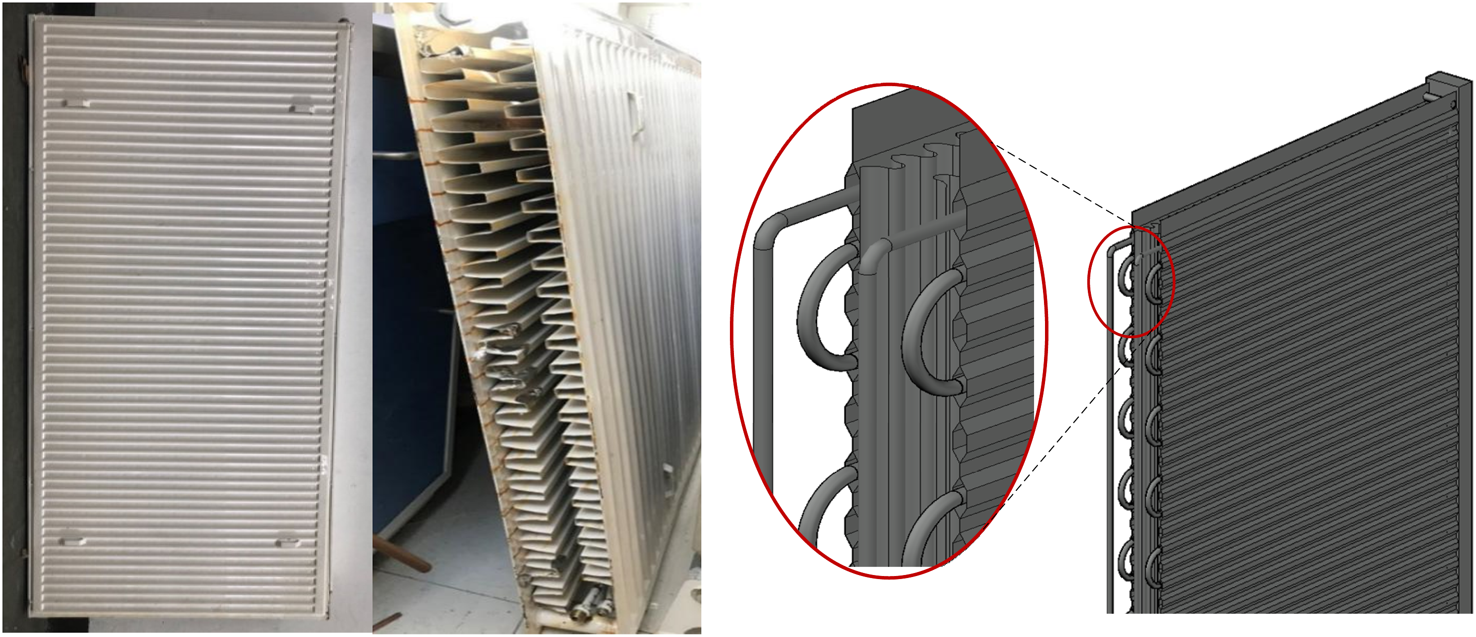
The CFD model of the RHR and the air conditioner was established based on the dimension of the experimental chamber to investigate the indoor thermal environment, as shown in Figure 2. The chamber size was 4.2 m × 3.5 m × 2.5 m (L×W×H). The western wall and southern wall of the chamber were exterior walls, and other walls were internal walls. The window with the size of 1.6 m × 1.2 m was located at the southern wall. The RHR was placed near the western wall with the distance of 0.1 m away from the wall and floor and the air conditioner was placed on the upper left of the western wall. The model of the chamber.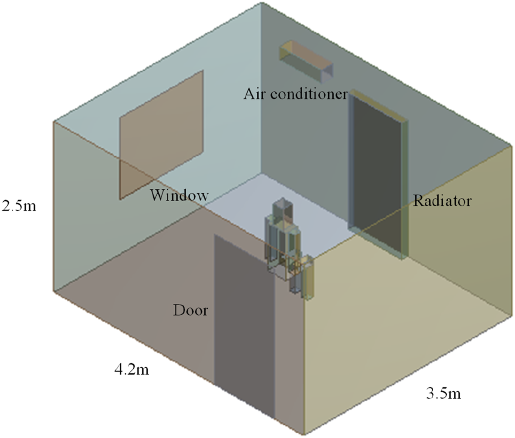
Governing equations
The fluent software was used to analyse the thermal performance of the RHR and the air conditioner.
The equations are as follows: (1) Continuity equation (Equation (1))
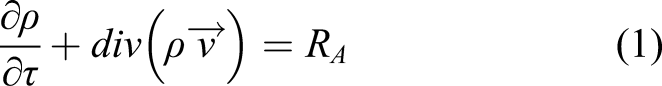
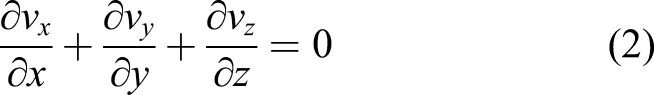
Equation (1) applies to compressible and incompressible fluid flows, which is a general form of the mass conservation equation. In this study, air was considered as incompressible fluid and there is no phase change in the heat transfer process, so equation (1) is simplified as equation (2)
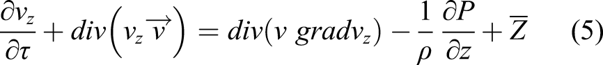
The variation of air density was considered in z direction, which could cause buoyancy force and would drive the air flow under the action of gravity. The Boussinesq approximate model was used in this model, which ignores the viscous dissipation of fluid. The density was considered to be constant in other equations except for the buoyancy term in the momentum equation.
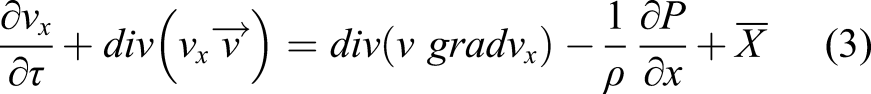
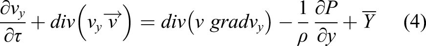
The density in the buoyancy term of the momentum equation is expressed as equation (6) (3) Energy equation (equation (7))

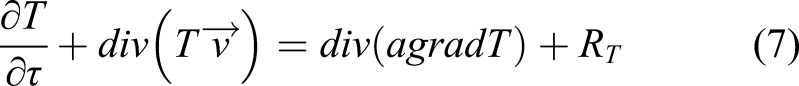
Equations (3)–(5), and (7) are in the general form, and first terms of these equations were omitted for the steady-state.
The standard k-ε model was used for the fluent operation and short calculation time. The discrete ordinates (DO) radiation model was adopted for radiation calculations.
Computational methodology
The room model was discretized on a hybrid grid by combing both structured and unstructured grids. The mesh division of interior space was divided into four parts: around the RHR (the air conditioner), around the human body, large space and the transition area from the RHR (the air conditioner) to the large space. Structured hexahedral mesh was adopted around the RHR (the air conditioner), with a minimum size of 2 mm. The large interior space was represented by structured hexahedral mesh with the size of 50 mm. The transition part of the RHR (the air conditioner) to the large space adopts size function and the unstructured grid was used. The human body was represented by dividing the mass into unstructured grids by size function. Grid independence test was conducted and the results indicated that the grid number of 5.04 million is accurate enough to predict temperature and velocity distributions.
In order to reduce the complexity of the mathematical mode, the heat transfer process was assumed to be steady-state conditions. In addition, air was assumed to be incompressible medium to adopt the Boussinesq approximation, and the heat of solar radiation passing through the window glass and the energy that were lost through the room gap were ignored.
The heat transfer coefficient of the window was 20 W·m−1·K−1. The thickness of exterior wall was 37 cm, and the thermal conductivity coefficient of exterior wall was 0.81 W·m−1·K−1. The outdoor temperature was set at 31.9°C in summer and -9.6°C in winter. The heat flux of manikin surface was 63 W·m−2 in summer and 84 W·m−2 in winter. The other walls were considered as adiabatic. The emissivity of wall surfaces was assumed as 0.9.
The Semi-Implicit Method for Pressure Linked Equations (SIMPLE) for coupling pressure-velocity was adopted. The Presto was used to discretize the pressure term. The first order upwind difference scheme was used to solve the governing equations.
Evaluation parameters
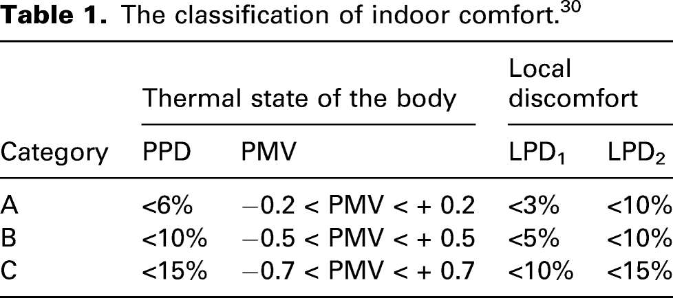
While a number of thermal comfort evaluation parameters are currently available, the most common used parameters are the predicted mean vote (PMV) and the percent persons dissatisfied (PPD). 29
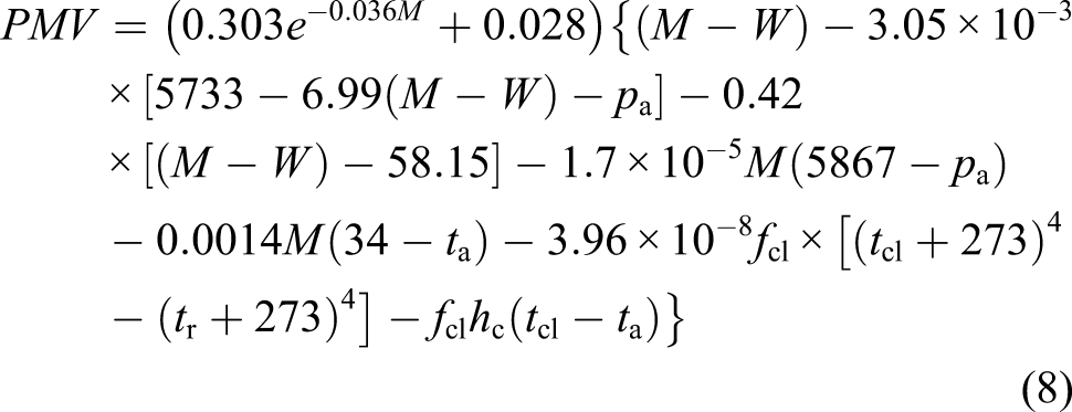
The calculation of PMV is given by equation (8)
30
PPD can be calculated by equation (9)
30

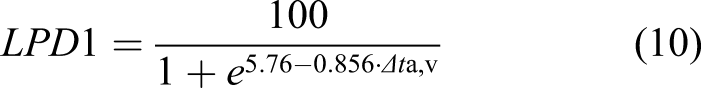
In addition, the local percentage of dissatisfied (LPD) caused by vertical air temperature gradient was employed, and the LPD1 was determined by equation (10) as
30
Local percentage of dissatisfied caused by warm and cool floors, the LPD2 was calculated as given by equation (11)

Model validation
Experimental system
In order to evaluate the CFD model, experiments were carried out in the experimental chamber, which consists of the indoor compartment and the outdoor compartment, as shown in Figures 3 and 4. The system used R410A as the refrigerant. The RHR and the air conditioner were installed in the indoor test chamber, and the heat pump unit was installed in the outdoor compartment. Schematic of experimental setup. The experimental chamber.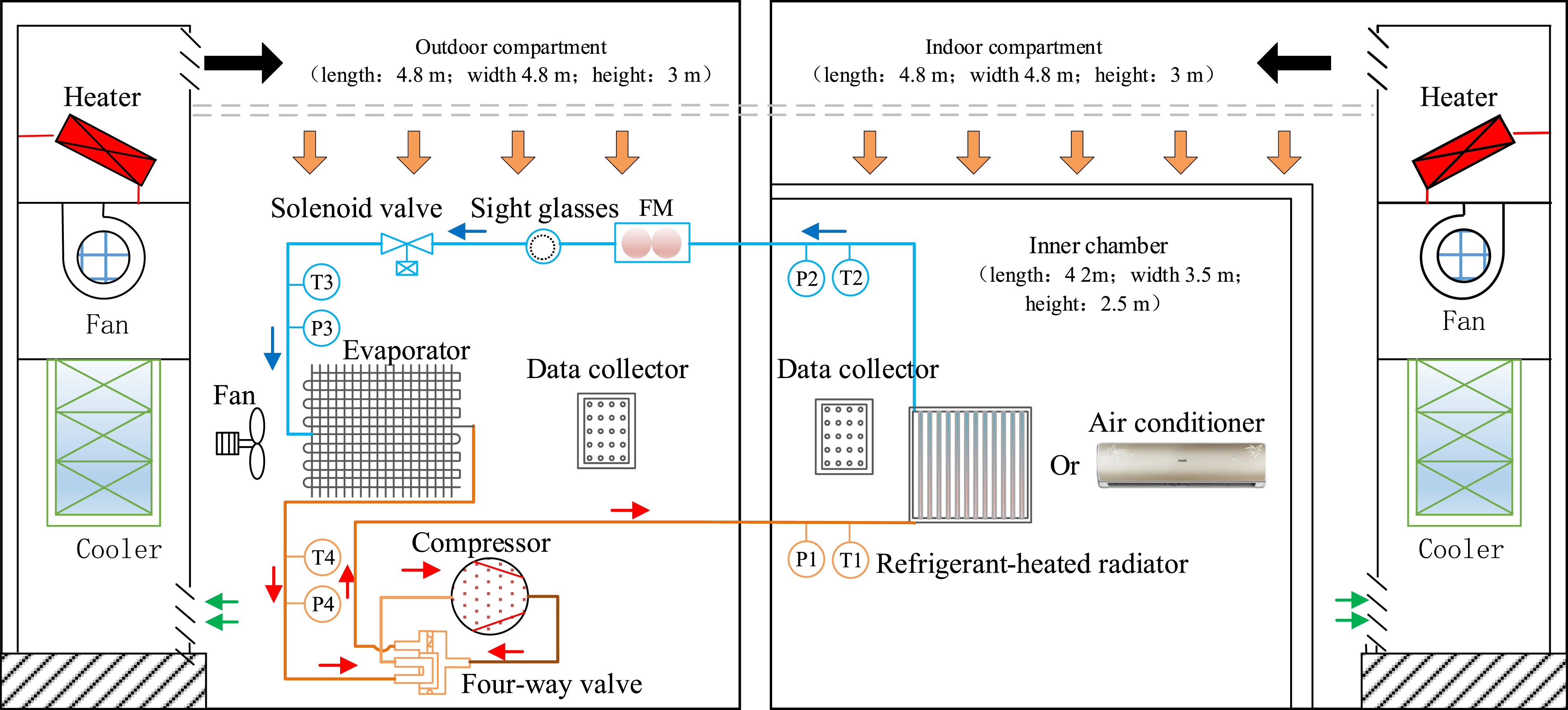
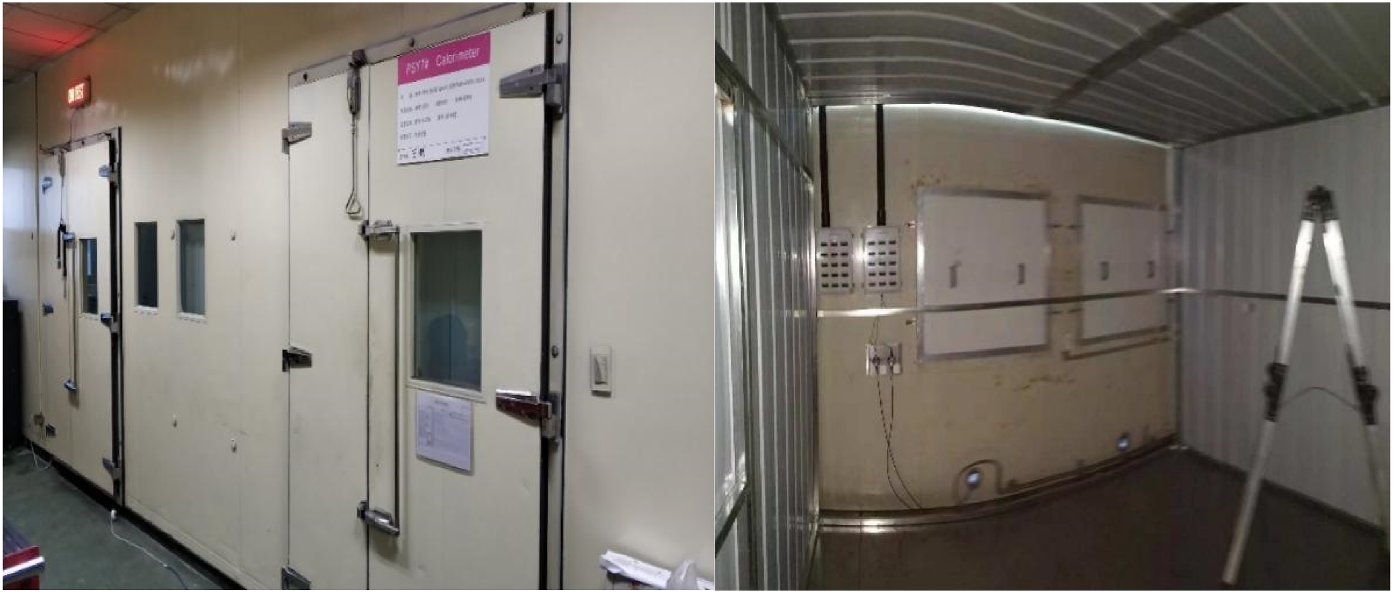
The outdoor unit consists of a dual-rotor variable frequency compressor, evaporator, four-way reversing valve, electronic expansion valve and gas-liquid separator. The nominal heating capacity and input power of the unit are 3500 W and 975 W, respectively. The indoor and outdoor compartments are separately controlled by a combined air conditioning unit. The air temperature and relative humidity (RH) in the test room were controlled within -20.0°C–60.0°C and 20%–90% RH, respectively.
The surface temperature of the RHR, indoor walls and indoor air temperature were measured by a copper-constantan thermocouple, which was recorded by the data acquisition collector every 2s. The measurement range of the copper-constantan thermocouple was -200–200°C with an accuracy of ± 0.1°C. 14 temperature sensors were evenly distributed on the surface of the RHR. The measuring points of the indoor environment are illustrated in Figure 5. Indoor air temperature measuring points distribution.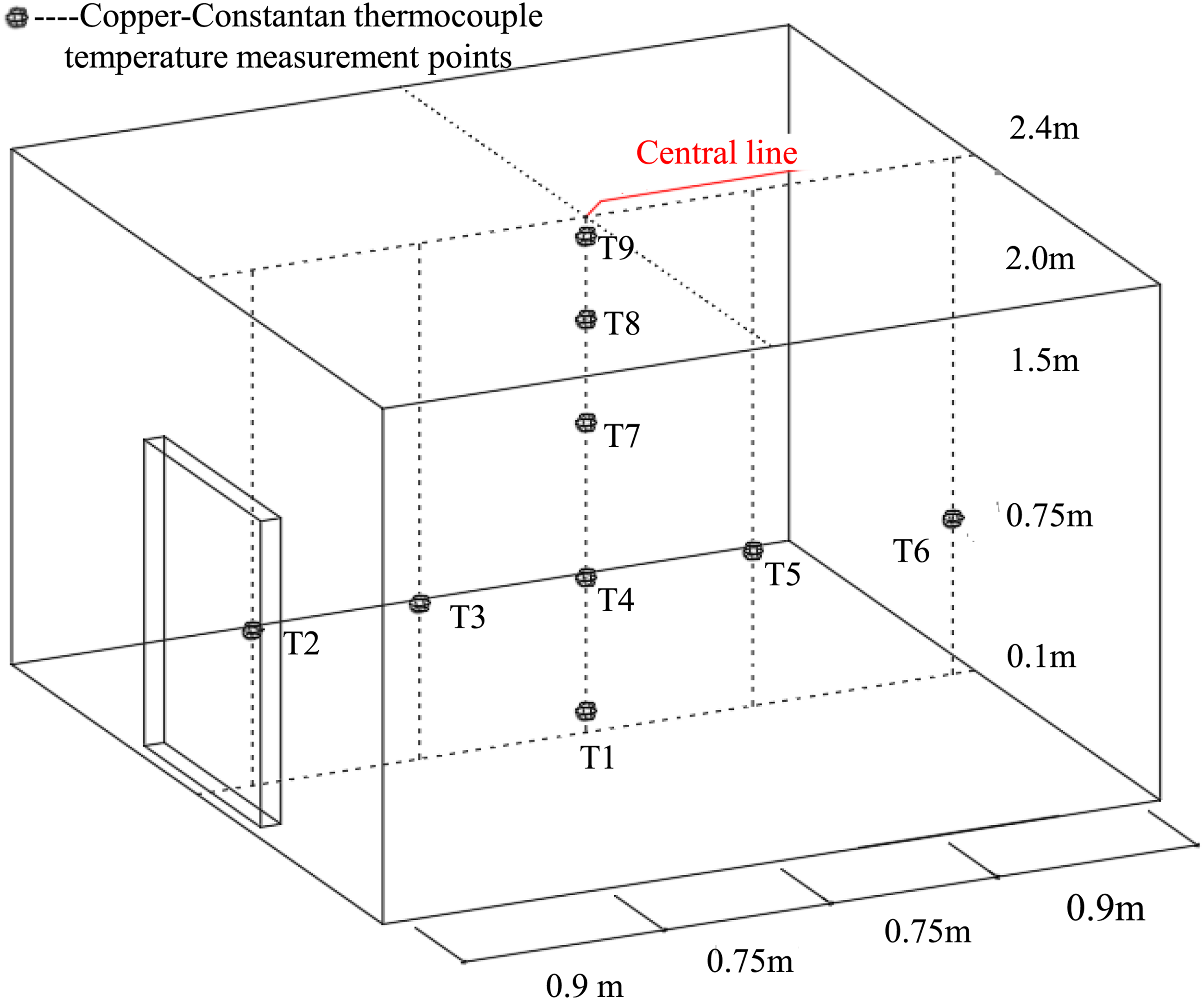
Model validation
The comparison of the indoor air temperature between the measured data and simulated results of the RHR were conducted under different surface temperatures of the RHR: 50°C, 46°C, 42°C, 21°C, 19.5°C and 18°C, as shown in Figure 6. Comparison of simulation results with experimental results for the RHR model. (a) Heating conditions. (b) Cooling conditions. (c) Relative error.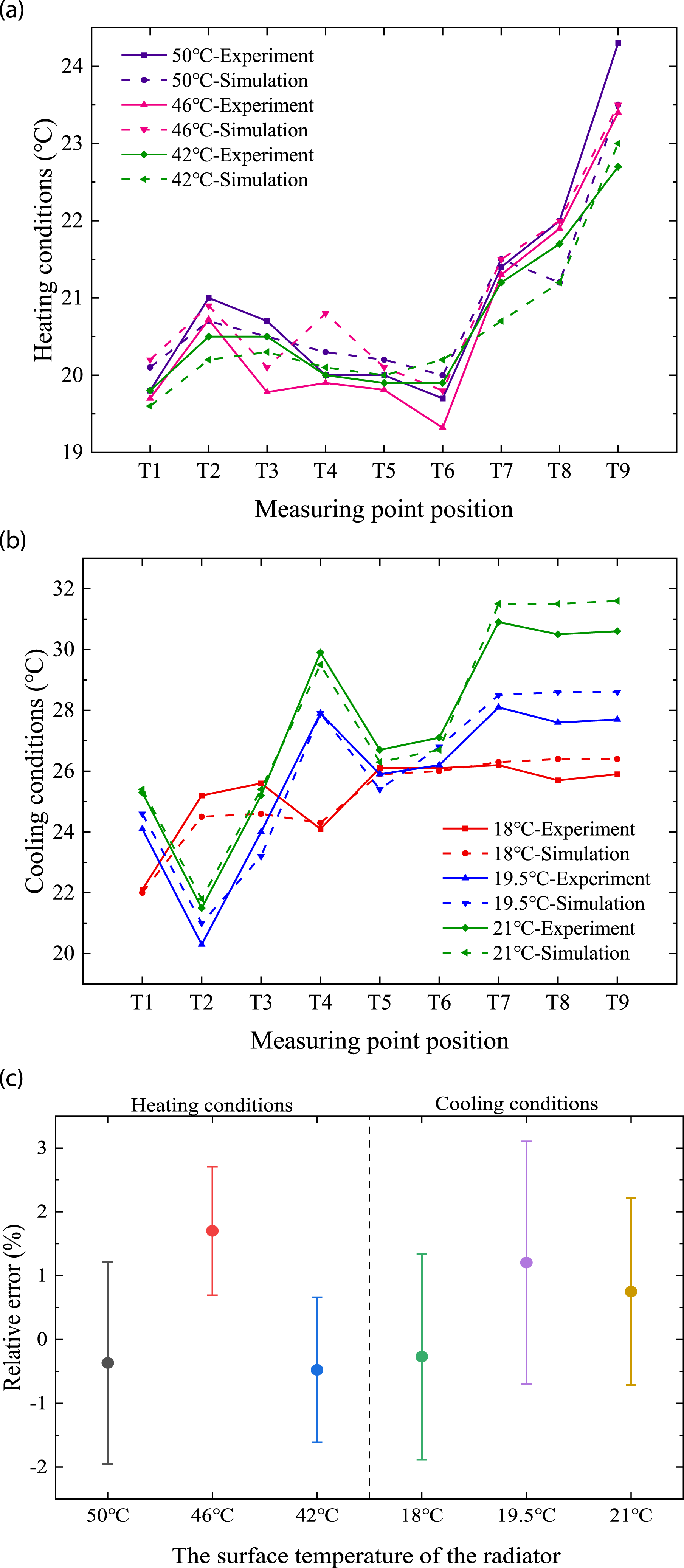
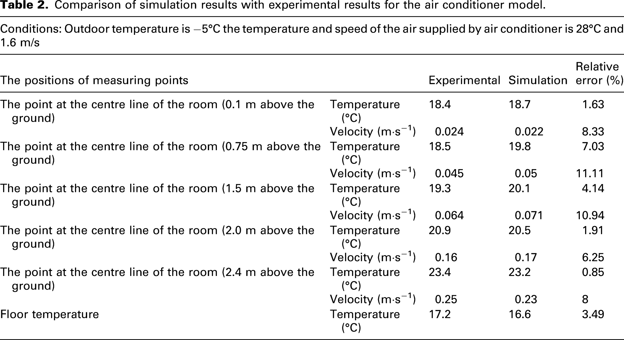
Comparison of simulation results with experimental results for the air conditioner model.
Results and discussion
Effects of length-to-height ratio on the indoor thermal comfort
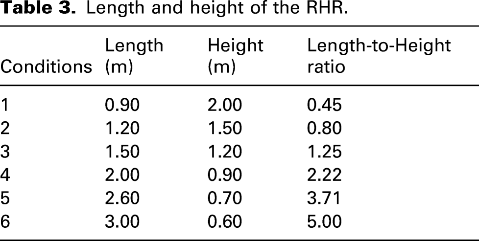
Length and height of the RHR.
Effects on the indoor air temperature field
Figure 7 shows the influence of RHR dimension on the indoor air temperature distribution in heating and cooling conditions, which illustrates the vertical temperature distribution at the centre of the RHR. There is an obvious temperature stratification in the vertical direction in the heating condition. The indoor air temperature would rise from the ground to the roof. The average air temperature in the personnel activity area (below 2 m) rose with the shortening of the length-to-height ratio, these were 17.3°C, 17.8°C, 18.3°C, 18.4°C, 19.6°C and 20.1°C. As the length-to-height ratio was increased, the air temperature in the area of personnel activity rose and the temperature gradient in the vertical direction became smaller. As illustrated in Figure 7(b) a temperature stratification was shown to exist in the vertical direction in the cooling condition. The higher temperature gradient occurred at the area near the ground in the heating condition due to the sinking of the cold air. As the length-to-height ratio was increased, the average air temperature in the area of personnel activity was 26.4°C, 26.3°C, 26.1°C, 25.9°C, 25.7°C and 25.6°C, showing a decline in the air temperature. From the above analysis, the cooling and heating effects of the RHR are enhanced by the increase of the length-to-height ratio. The temperature field in vertical section with various RHR dimensions. (a) Heating. (b) Cooling.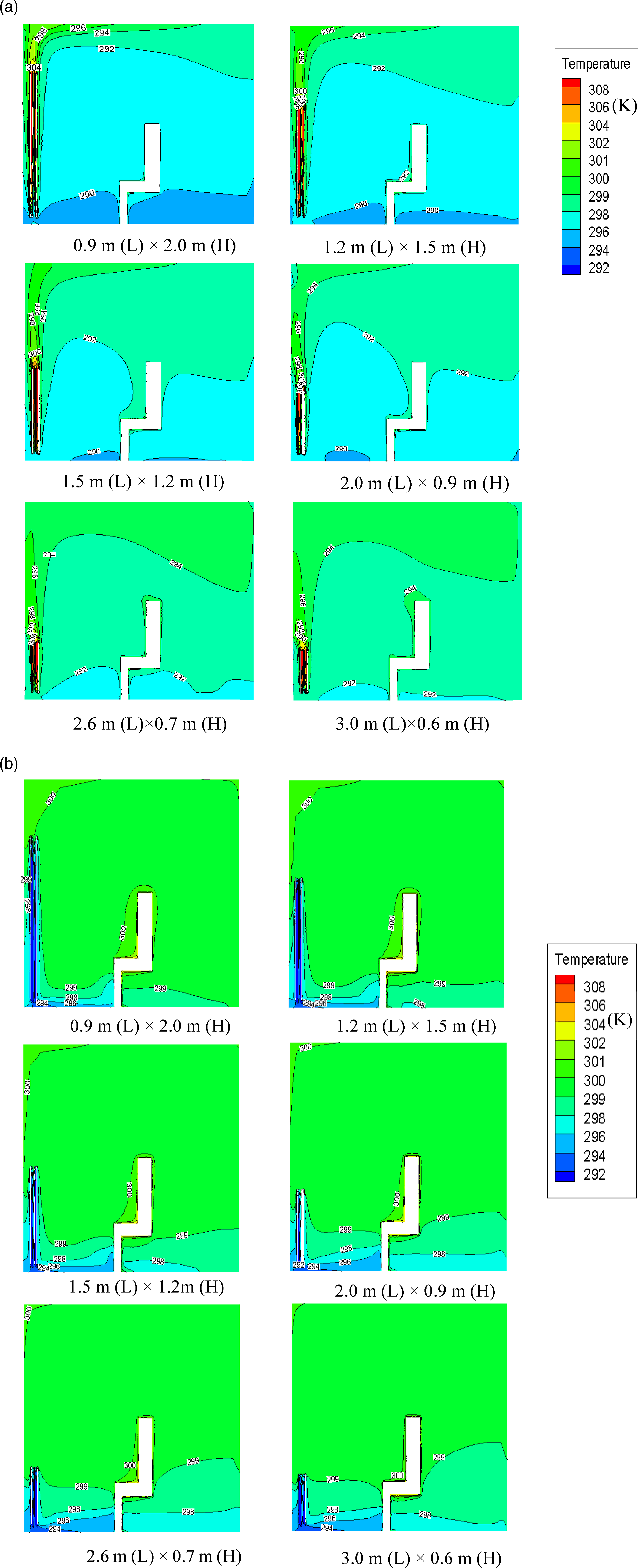
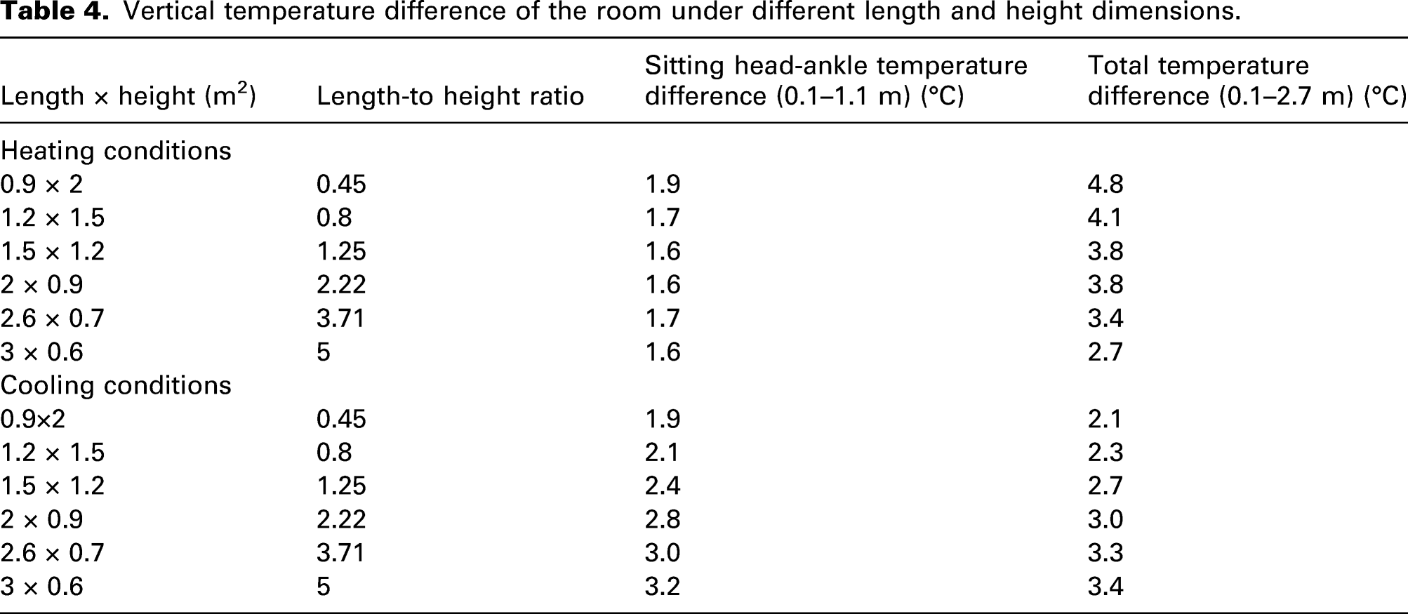
Vertical temperature difference of the room under different length and height dimensions.
Effects on the indoor air velocity field
Figure 8 shows the influence of RHR dimension on the velocity distribution. As the length-to-height ratio of the RHR was increased, the maximum wind speed declined from 0.74 m·s−1 to 0.53 m·s−1 in the heating condition. The average wind speed in the area of personnel activity was between 0.04 m·s−1 ∼ 0.07 m·s−1, which was far less than 0.2 m·s−1 and can meet the requirements of indoor thermal comfort. Similarly, the average wind speed was 0.02 m·s−1∼0.03 m·s−1 in the cooling condition. Compared with the heating condition, the maximum wind speed in the cooling condition is smaller, and the area of the wind speed greater than 0.1 m·s−1 was smaller, which indicates that the effect of the natural air convection is more significant in the heating condition. The flow field in the vertical section with various RHR dimensions. (a) Heating. (b) Cooling.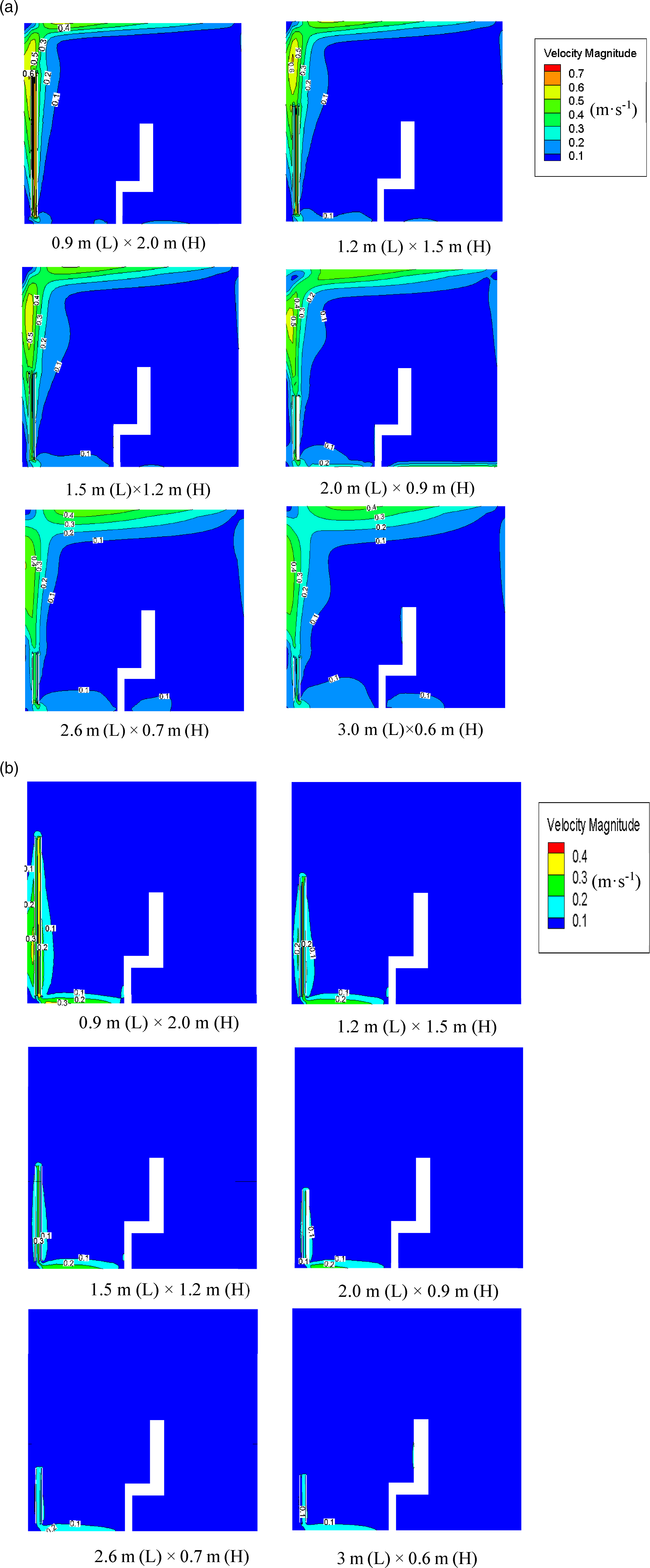
Effects on the indoor thermal comfort
PMV-PPD indices of sitting people with various RHR dimensions.
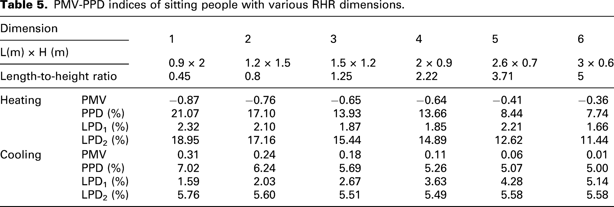
The LPD1 was influenced by the vertical air temperature gradient, which mainly relies on the air temperature at the height of the head and ankle. From Table 5, the LPD1 is shown to have met category A (LPD1 < 3%) in all heating conditions. The larger the length-to-height ratio, the lower the dissatisfaction rate. On the contrary, with the increase of the length-to-height ratio, the LPD declined from category A (LPD1 < 3%) to category C LPD1 < 10%) in the cooling condition.
The LPD2 was influenced by the surface temperature of the floor. From Table 5, the LPD2 declined from 18.95% to 11.44% as the length-to-height ratio was increased under the heating condition. The LPD2 can meet category C (LPD2 < 15%) when the length-to-height ratio is larger than 1.25. The fluctuation range of PD2 with the variation of length-to-height ratio was not large under the cooling condition, and the LPD2 met category A (LPD2 < 10%) in all cooling conditions.
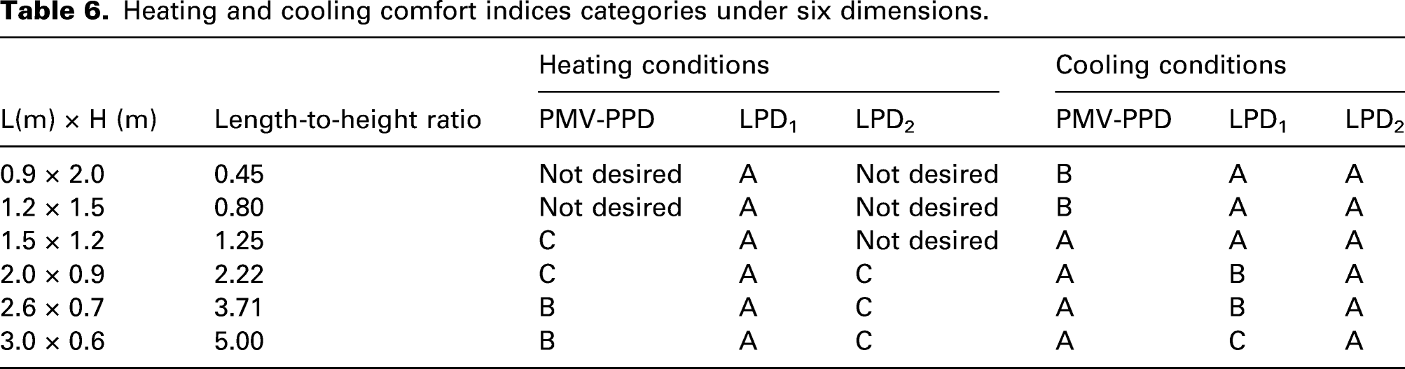
The optimization of the length-to-height ratio
Heating and cooling comfort indices categories under six dimensions.
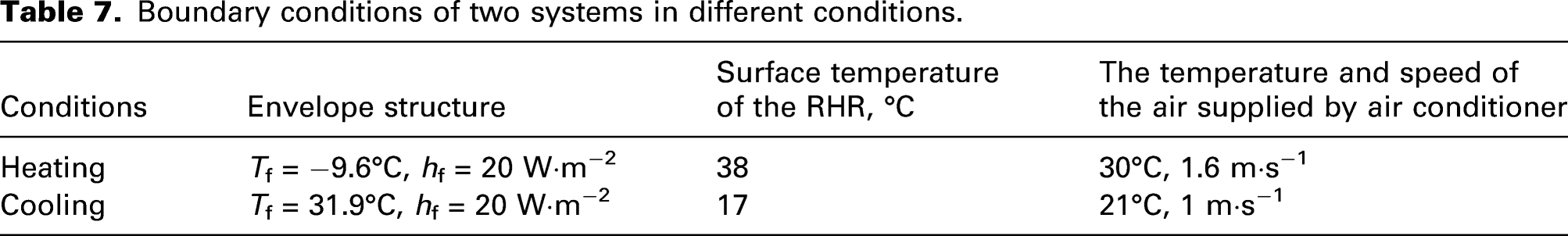
Comparison of effects of the refrigerant-heated radiator and air conditioner on the thermal comfort
Boundary conditions of two systems in different conditions.
The temperature distribution in heating and cooling is shown in Figures 9 and 10. As shown in Figure 9, when the air conditioner was used for heating, the indoor temperature field was unevenly distributed. Due to forced convection heat transfer, the temperature can reach 21–23°C at its air outlet, which is significantly higher than in other areas. At the same time, due to the hot airflow that cannot be reached near the ground, a large vertical temperature difference would arise in the area of personnel activity (Below 2 m) which could easily cause discomfort. In contrast, when using a radiator for heating, the vertical temperature difference was smaller, and the horizontal temperature difference at the same height in the area of personnel activity was less than 1°C, which is very uniform. The vertical temperature gradients are summarized in Table 8. The vertical sitting head-ankle temperature difference of the heating of the radiator would be 1.5°C, the air conditioner was shown to produce a larger vertical temperature difference during heating. The temperature difference exceeded 3°C in the area of personnel activity, which may easily cause the discomfort of a hot head and cold feet. Therefore, the RHR system could provide a more comfortable thermal environment than the air conditioner in the heating condition. Indoor temperature distribution of two systems in the heating condition. (a) The indoor temperature distribution of air conditioner in heating condition. (b) The indoor temperature distribution of RHR in the heating condition. Indoor temperature distribution of two systems in cooling condition. (a) The indoor temperature distribution of the air conditioner in cooling condition. (b) The indoor temperature distribution of the RHR in cooling condition. Vertical temperature difference of the room under different length and height dimensions.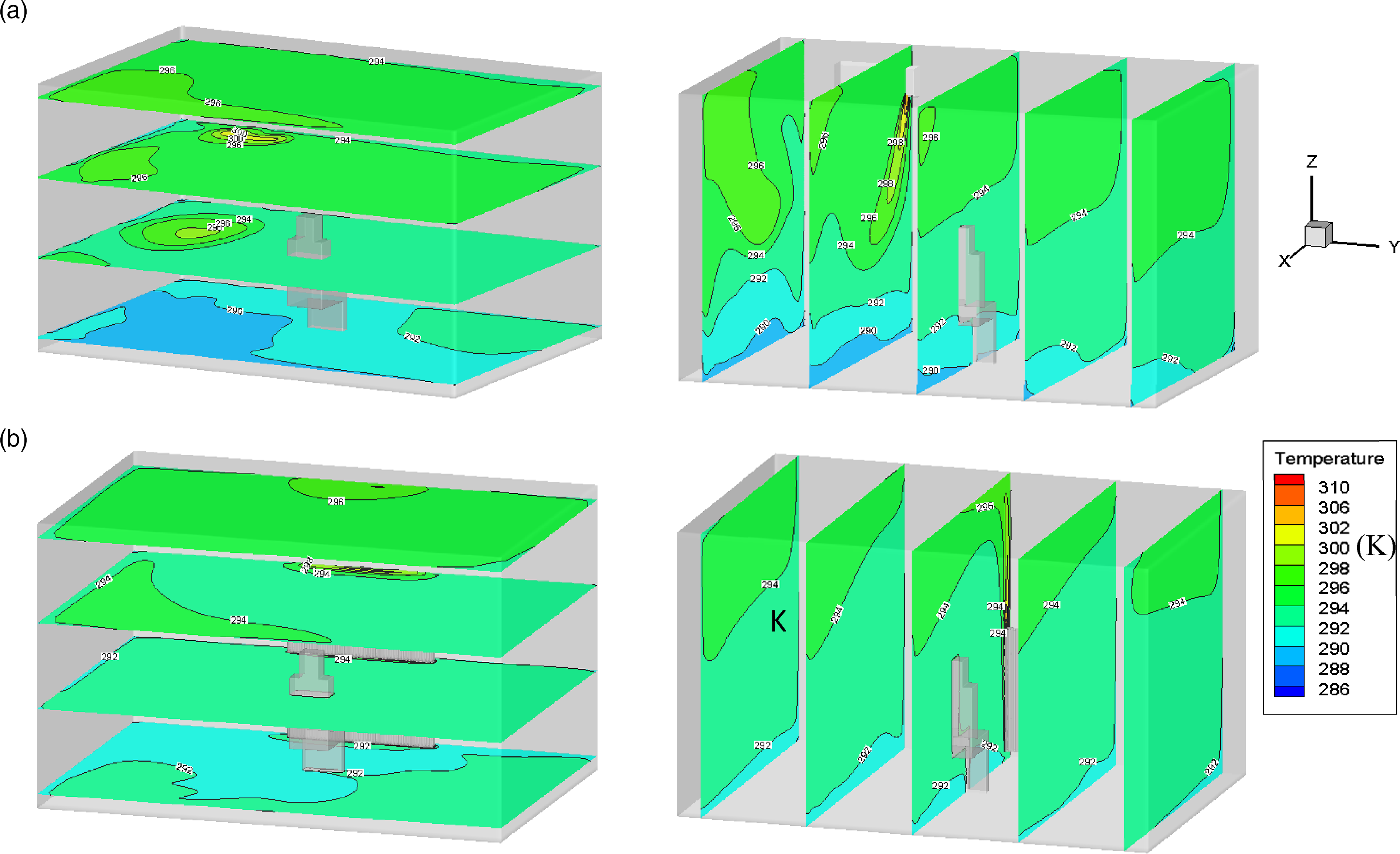
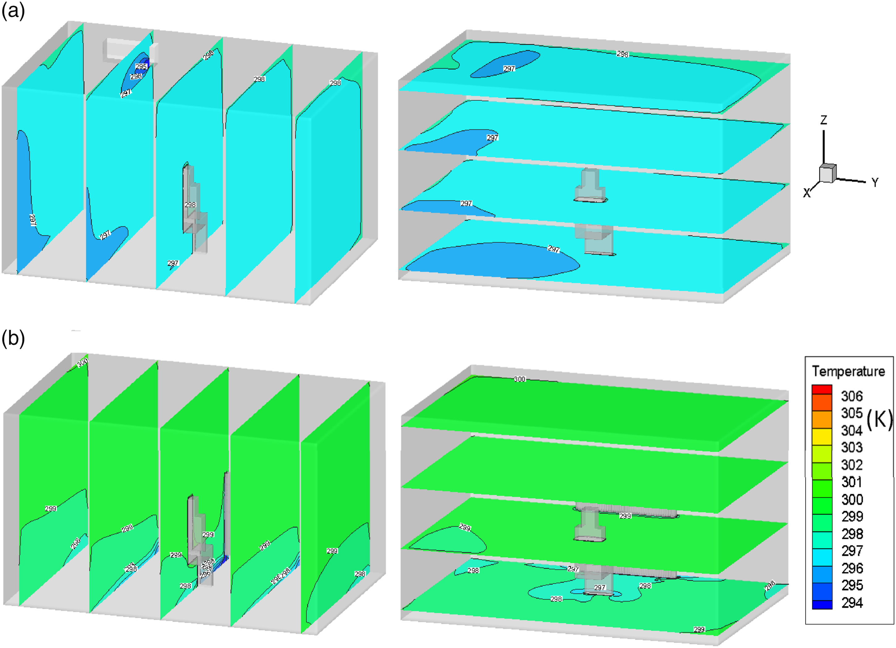
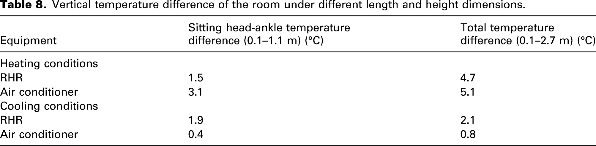
As shown in Figure 10 and Table 8, the air temperature distribution in areas beyond the outlet was uniform for the air conditioner in the cooling condition, and the temperature difference was about 1°C in the vertical and horizontal direction. Correspondingly, the temperature difference was less than 3°C in the personnel activity area in the RHR cooling condition, while the temperature in the area of the ankle (0.1 m) was as low as 22°C due to the sinking of the cold air. Furthermore, the temperature distribution in the personnel activity area was between 23 ∼ 24°C for the air conditioner cooling while it was 25–27°C for RHR cooling. Hence, the air conditioner has a better cooling performance than the RHR in the same cooling capacity.
The velocity distributions under heating and cooling conditions are shown in Figures 11 and 12. From Figure 11, the maximum air velocity in the personnel activity area was greater than 1 m·s−1 of the air conditioner in the heating condition, which would cause a strong sense of air draught. The area with a strong sense of air draught affected nearly 1/4 of the indoor space, while the air velocity in the area not directly facing the air outlet was less than 0.2 m·s−1. As for the RHR heating, the air velocity directly above the RHR was greater than 0.3 m·s−1 due to the effect of significant natural convection. The average air velocity in the personnel activity area was 0.04 m·s−1, which was far less than 0.2 m·s−1 and can meet the requirement of indoor thermal comfort. Indoor air velocity distribution of two systems in heating condition. (a) Velocity distribution of the air conditioner in heating condition. (b) Velocity distribution of the RHR in heating condition. Indoor air velocity distribution of two systems in cooling condition. (a) Velocity distribution of air conditioner in cooling condition. (b) Velocity distribution of RHR in cooling condition.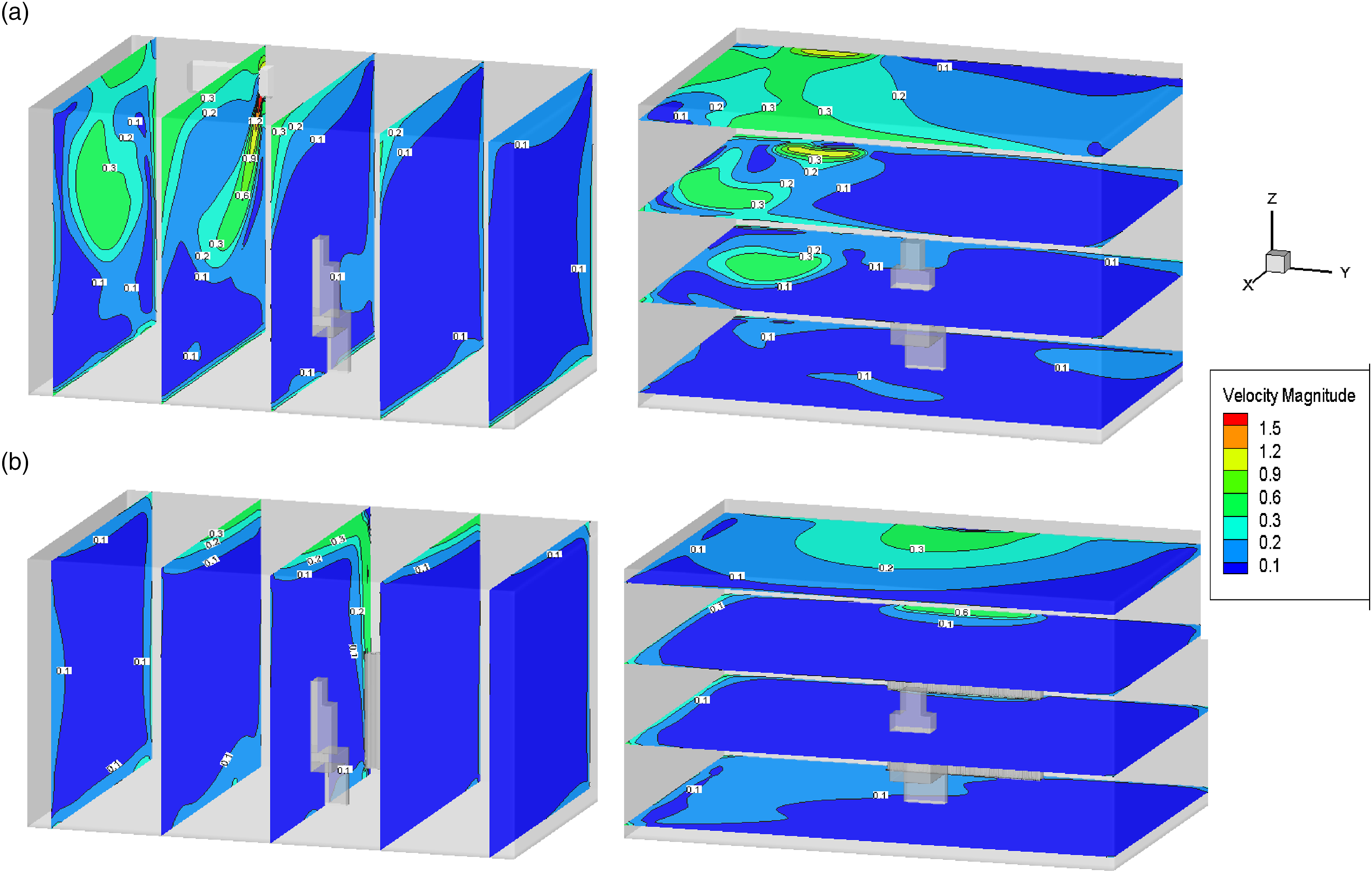
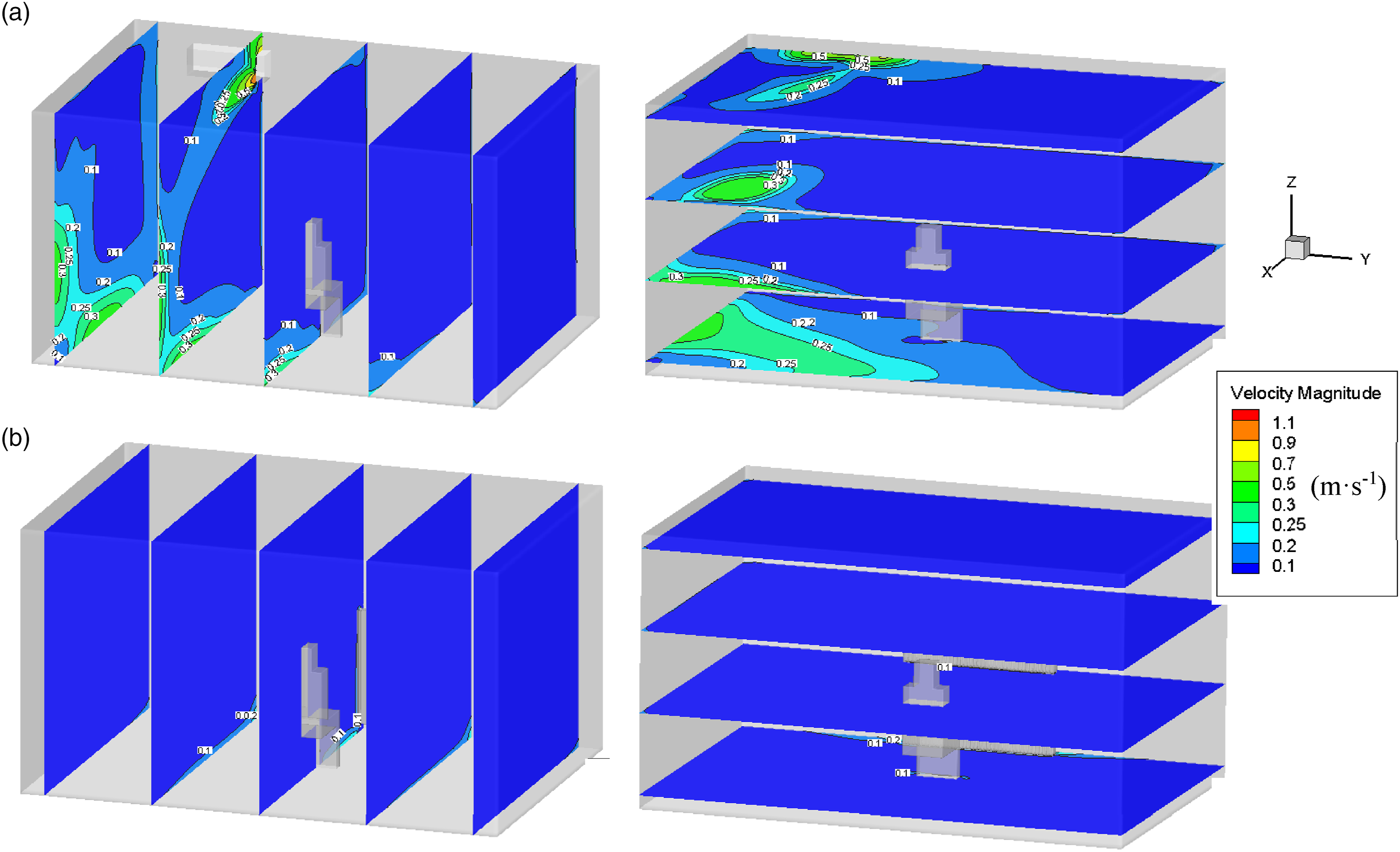
Figure 11 illustrates the indoor air velocity distribution of two systems in the cooling condition. It shows that the air velocity of the air conditioner in the personnel activity area was about 0.15 m·s−1 while it was only 0.02 m·s−1 for the RHR cooling. Thus, the RHR has a better performance in the flow field distribution than that of the air conditioner in both cooling and heating conditions.
The weighted average was used to calculate the PMV-PPD for the environment with uniform temperature and airflow distribution. The heights were 0.1 m, 0.6 m and 1.1 m away from the ground for a sitting person. Five points were selected in a line to evaluate the PMV-PPD, as shown in Figure 13. PMV-PPD calculation points.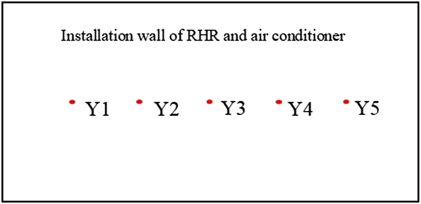
Installation wall of the refrigerant-heated radiator and air conditioner
PMV-PPD indices of sitting people under different conditions.
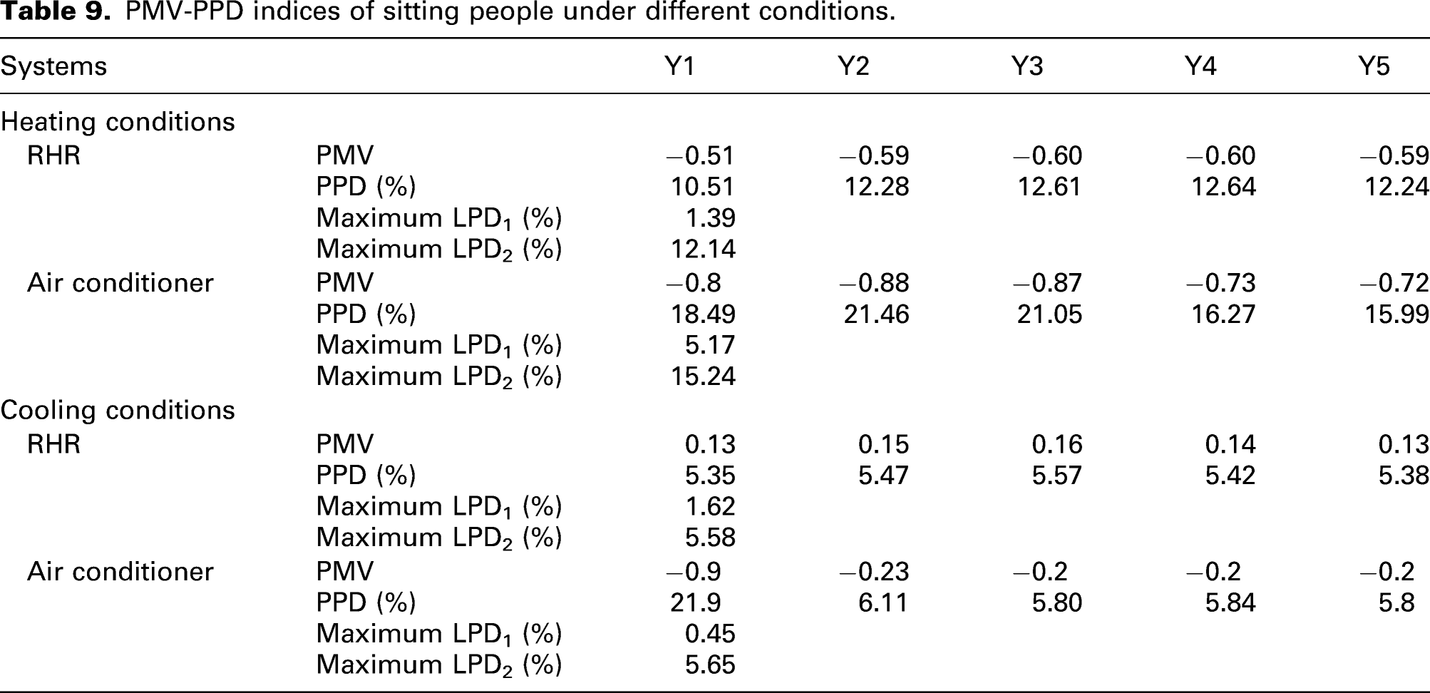
The PMV-PPD distribution of the RHR in the cooling condition was more uniform, and the PPD fluctuation was less than 0.73%, while the PPD of an air conditioner cooling at Y2 would reach 20% and it was significantly higher than other positions. In addition, the PMV was less than zero and the thermal sensation would be cooler.
The indoor thermal environment of the RHR is more uniform with smaller fluctuation. In addition, the LPD1 of the RHR meets category A (<3%), the LPD1 of an air conditioner meets category C (<10%) and A (<3%) in winter and summer, respectively. The results indicate that the RHR is better than the air conditioner in terms of the LPD1. The LPD2 of RHR meets category C (<15%) and A (<10%), the LPD2 of an air conditioner is not desirable in winter (<15%) and can meet category A (<10%) in summer.
Conclusion
The indoor comfort of the refrigerant-heated radiator is an important index to evaluate its performance. Compared with room air conditioners with a forced convection for heat exchange, the refrigerant-heated radiator exchanges heat with the environment through natural convection and radiation. Quantitative analysis can intuitively compare indoor thermal comfort with these two terminals. At the same time, the refrigerant-heated radiator can be used for both winter and summer, and the study of the length-to-height ratio on its heating and cooling comfort is helpful to improve the structural design.
In this paper, the CFD model of RHR and air conditioner for heating and cooling were established and were validated by experiments. Effects of RHR with different length-height ratios on thermal comfort were analysed and compared with the air conditioner. The following conclusions are drawn from the study: (1) As the increase of length-height ratio, the heating effect and thermal comfort of the RHR are enhanced, while the dissatisfaction rate caused by vertical temperature gradient is relatively low. (2) As the length-to-height ratio is increased from 0.45 to 5, the cooling effect and the overall thermal comfort of the RHR are enhanced, while the vertical temperature gradient and the LPD1 and LPD2 are increased. When the length-to-height ratio is larger than 3.71, the head-to-ankle temperature difference of the sitting person would exceed 3°C, which exceeds the recommended value in ASHRAE. Therefore, the length-to-height ratio of the RHR is preferably to be lower than 3.71. (3) By comparing temperature field, velocity field and thermal comfort indices in the heating and cooling conditions, the optimum length-height ratio range of RHR should be 2.22–3.71. (4) The performance of RHR heating is better than that of the air conditioner in terms of temperature field, velocity field and thermal comfort indices. In the cooling condition, the air conditioner has a lower temperature distribution in the personnel activity area and a more uniform vertical temperature distribution, while the RHR is prominent in the velocity distribution and the overall thermal comfort indices. Combining the thermal comfort in heating and cooling conditions, the RHR has a better thermal performance.
Footnotes
Acknowledgements
The authors are grateful for the financial support provided by the National Natural Science Foundation of China (No. 51808386) and National Science Foundation of Tianjin City (20JCQNJC01910).
Authors’ contributions
All authors contributed equally in the preparation of this manuscript.
Declaration of conflicting interests
The author(s) declared no potential conflicts of interest with respect to the research, authorship and/or publication of this article.
Funding
The author(s) received no financial support for the research, authorship and/or publication of this article.