
Abstract
The south building of Huadong Hospital is a well-known historic building in Shanghai, China. In August 2021, the building was lifted by 1.30 m to correct the subsidence caused by long-term use and to expand the usable space of the building. To ensure structural safety during uplifting of the historic building, a structural health monitoring system is devised to monitor the overall status of the structure and the state of critical components. The structural health monitoring system comprises sensor, data acquisition, and data management systems. The content that is monitored includes vertical displacement, horizontal displacement, inclination, differential settlement, cracks, strains, and acceleration. The overview and uplifting scheme of the historic building are first introduced. The monitoring system’s design and sensor installation are then thoroughly discussed, followed by monitoring data analysis to investigate the state of the structure before and after uplifting. Furthermore, a structural safety assessment based on multisource monitoring data and neural networks is conducted. Huadong Hospital’s south building is currently the largest uplifted historic building in terms of construction area in China. The building’s structural health monitoring system played an exemplary and promoting role in structural health monitoring during uplifting of historic buildings, and it also has referential significance for similar engineering projects.
Keywords
Introduction
Building uplifting is effective building renovation technology that can lift a building from its original location to a higher one, which can be used to reinforce the building while maintaining its original appearance. This approach enables the correction of excessive settlement of buildings, increase the underground space, ensures structural safety, and prolongs the service life of the building.1–4 Compared with demolition and reconstruction, building uplifting often results in lower costs and shorter times while preserving the original appearance of some important historic buildings. Thus, building uplifting plays an important role in alleviating the shortage of urban land, regeneration of building functions, and protection of historic buildings.5–7 Recently, uplifting of buildings has been used in some building renovation projects and has achieved good results.8–12 For example, the great hall of Nanjing Museum, which is a 78-year-old historic building, was lifted by 3.0 m owing to the need for extension and seismic isolation retrofit. 2 The renovation project of Jade Buddha Temple also adopts building uplifting to reinforce the Mahavira Hall, improving the seismic performance and prolonging the service life of the building. 12
Building uplifting often involves the following process. First, the underpinning beam should be manufactured to support the entire building. Second, the building is separated from its foundation and temporarily supported with jacks. After the building is moved to the predetermined location by jacks, a new foundation and support should be manufactured, and the jacks retracted. Finally, the building is then moved to a higher position to reduce the threat of flooding and soil erosion, increase the headroom of the basement, or help replace the settling foundation. 13
However, the building may encounter many dangerous situations during the uplifting process, including excessive vertical displacement differences, horizontal movement of the building, inclination of the overall building, and component failure due to crack expansion in critical components.14,15 These dangerous situations are mainly due the unsynchronized vertical uplifting displacement, excessive uplifting speed, vibration generated when the jack starts and stops and the failure of some jacks during the uplifting process. These issues pose safety risks to the uplifted buildings and may even cause damage or building collapse, resulting in severe casualties and property losses. Therefore, uplifting projects often require stringent process control during the uplifting process, and a structural health monitoring system should be adopted to determine the structural status in real time. A structural health monitoring system is especially important for some historic buildings with strict protection requirements.16–18
Some current structural health monitoring systems for historic buildings, such as the monitoring system of the Milan Cathedral, collect static and dynamic measurement building data.19–24 The structural health monitoring system of the Milan Cathedral focuses on the long-term monitoring of the static building and helps us determine the condition of the cathedral in real time. 24 It is also adopted during the translocation of Jade Buddha Temple’s Mahavira Hall. The distributed sensor network includes hydrostatic leveling, inclinometers, and laser displacement meters. 12 However, to achieve more comprehensive monitoring of historic buildings during the uplifting process, the design and implementation of structural health monitoring systems should still be further investigated.
Structural health monitoring systems typically obtain massive amounts of monitoring data during the monitoring process. The method used to assess building safety based on multisource and massive monitoring data has attracted research attention in recent years. In this regard, various methods, such as cluster analysis, expert systems, neural networks, fuzzy logic, and some other smart algorithms, have been used in monitoring data analysis and structure assessment.25–28 However, for special engineering projects, such as building uplifting projects and translocation projects, the method used to assess the safety of the building based on monitoring data also requires further investigation.
As a famous historic building, the south building of the Huadong Hospital is now protected as a municipal heritage building in Shanghai. The south building was uplifted by 1.30 m in August 2021 to correct the subsidence caused by long-term use. Furthermore, the uplifting of the building helps expand the usable space of the building and add isolation bearings. In terms of construction area, Huadong Hospital’s south building is currently the largest uplifted historic building in China; therefore, this project has some difficulties and risks. To ensure structural safety and minimize risks during the uplifting process, a structural health monitoring system was adopted for this building to monitor the structural status during the uplifting process. The structural health monitoring of the south building of Huadong Hospital focuses on the overall status of the structure and the state of critical components. The overall status, such as displacement and inclination, is closely related to the safety of the building during uplifting. These monitoring data can help adjust the jacks in time, thus providing assistance with the safe uplifting of the building. Furthermore, as a municipal heritage building in Shanghai, there are also many critical protection components with strict requirements that must be monitored and protected.
This paper presents the structural health monitoring system design and data analysis for the south building of the Huadong Hospital. The structural health monitoring system consists of a sensor system, data acquisition and transmission system, and data management system. The structural health monitoring system can monitor and display the vertical displacement, horizontal displacement, inclination, differential settlement, cracks, strain, and the acceleration of the building in real time, providing a reliable guarantee for the safety of the overall building during the uplifting process. Considering the complex and irregular layout, the large uplifting distance, enormous weight, and historical and cultural values of the building, this uplifting project is considered unique and representative, and has particularly referential significance to similar engineering projects.
The remainder of this paper is organized as follows. First, the overview and uplifting scheme of the south building of Huadong Hospital is introduced. Then, the design of the structural health monitoring system for the building to be uplifted and the sensor installation are explained in detail. The monitoring data of the south building during the uplifting process are also introduced. Analysis and safety assessment based on monitoring data were conducted to study the building status during uplifting. Finally, the future application prospects and challenges of the structural health monitoring system used in uplifting buildings are discussed.
Overview and situation prior to uplifting of Huadong Hospital’s south building
Huadong Hospital, formerly known as Country Hospital, is located at Yan’an West Road, Shanghai. 29 The south building of Huadong Hospital was designed by a famous Hungarian architect Ladislaus E. Hudec in 1923, and was constructed by the Pan Rongji Construction Company. 30 It was completed and opened in early June 1926. The south building of Huadong Hospital is a well-known historic building that is now protected as municipal heritage building in Shanghai. During its nearly 100 years of use, the south building of Huadong Hospital encountered significant subsidence of approximately 1.0 m. The indoor floor was 0.6–0.7 m lower than the outdoor floor, resulting in significant inconvenience in the use of the hospital. Therefore, this building was uplifted and an isolation system added to improve its flood protection capability and anti-seismic performance.
The south building of Huadong Hospital is a six-story building with a basement in the northwest corner of the building. Most structural foundations are strip foundations that are reinforced with wooden piles. The length of the building is 80.01 m from east to west, and the width is 44.95 m from south to north; the height of the building is 29.45 m. The overall weight of the building is approximately 25,000 tons. The building plan is H-shaped, the plan view of the building is shown in Figure 1, and the front view of the building is shown in Figure 2. The overall structure of the building is approximately a reinforced concrete frame structure, and the partial structure is a concrete wall bearing. The partial basement, elevator, and top floor exterior walls are reinforced concrete walls. The vertical load of the building is mainly supported by reinforced concrete frame columns, and the roof of each floor uses cast-in-place reinforced concrete beams to bear the load.
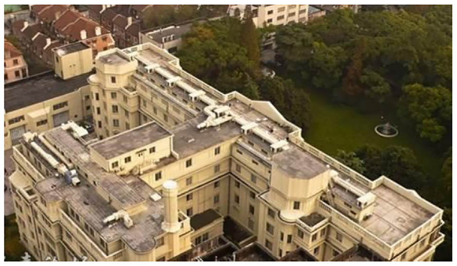
Plan view of Huadong Hospital’s south building.
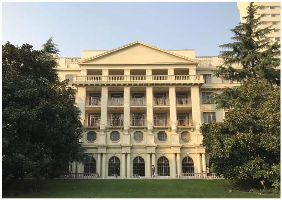
Front view of Huadong Hospital’s south building.
Over its history of nearly 100 years, the south building of Huadong Hospital has undergone several reconstruction projects. For example, in 1998, it underwent major renovation and reinforcement, and some elevator rooms were expanded. Generally, the structural system and architectural style of the building remained mostly in the original state. However, the overall posture of the structure had undergone some changes compared with the initial posture, such as its differential settlement and irregular inclination. Prior to uplifting, the overall state and structural damage to the building were as follows:
(1) After long-term use, the building had experienced significant subsidence of approximately 1.0 m (Figure 3). The indoor floor was 0.6–0.7 m lower than the outdoor floor, and was prone to flooding by rainwater into the building on rainy days.
(2) The main building on the south side was slightly inclined to the north and the sub-building on the north side was slightly inclined to the south. The maximum north–south inclination was 5.41%, and the east–west inclination was irregular.
(3) Differential settlement of the building. The relative settlement difference of the main building was 119 mm, the north side was slightly lower than the south side, and the relative settlement difference of the sub-building was 98 mm, which was slightly higher in the north and lower in the south. In the east–west direction, the settlement of the main building was larger in the middle and smaller at both ends, and the settlement difference of the sub-building was not obvious.
(4) The structural damage of the building included the following: some holes in the concrete floor, partially damaged concrete beams and columns, exposed and corroded steel bars, and widespread cracks in walls and windowsills.
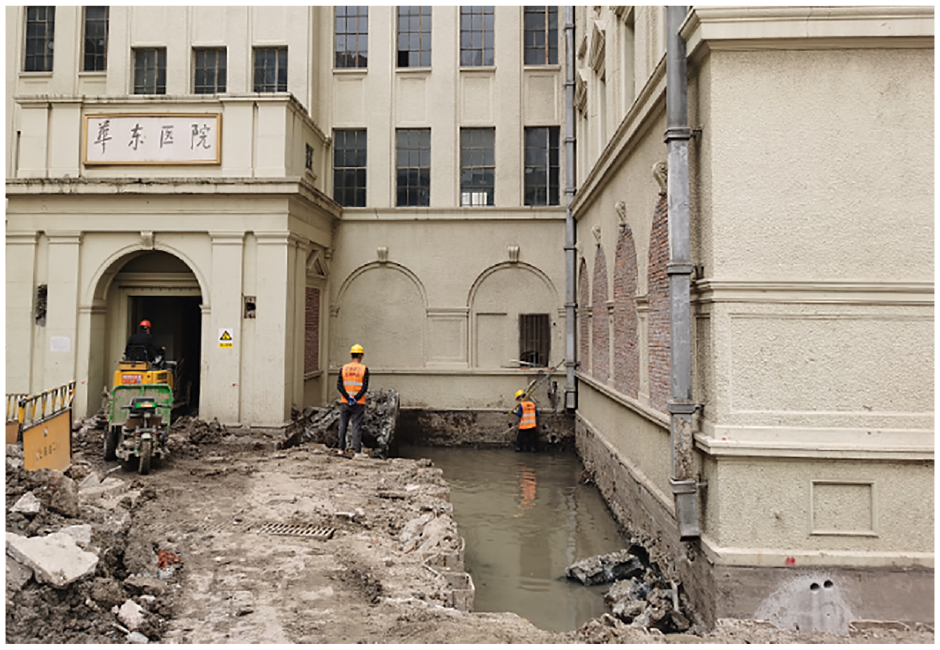
Building settled about 1.0 m in nearly a 100 years.
The subsidence of buildings often results in rainwater backflow on rainy days, which causes great inconvenience to the use of buildings. Furthermore, considering the aging of the building foundation, it was necessary to add seismic isolation bearings to increase seismic capacity. Thus, uplifting and renovation were required.
Uplifting scheme employed
To lift the building, the structure was first underpinned. Reinforced concrete joints at the root of the building’s column and wall were manufactured, and the joints tied by horizontal reinforced concrete beams to form an integral underpinning beam and provide in-plane stiffness. Subsequently, the soil beneath the underpinning beam was excavated, and concrete-filled steel tube piles constructed to support the entire building. After completing the construction of the concrete foundation plane, jacks were placed between the underpinning beam and foundation plane, and the piles were cut off to allow the vertical loads of the building to be transferred to the jacks. Finally, the building was moved to the final position using jacks; isolation bearings were manufactured to support the building, and the jacks were retracted. The proposed construction scheme is shown in Figure 4.
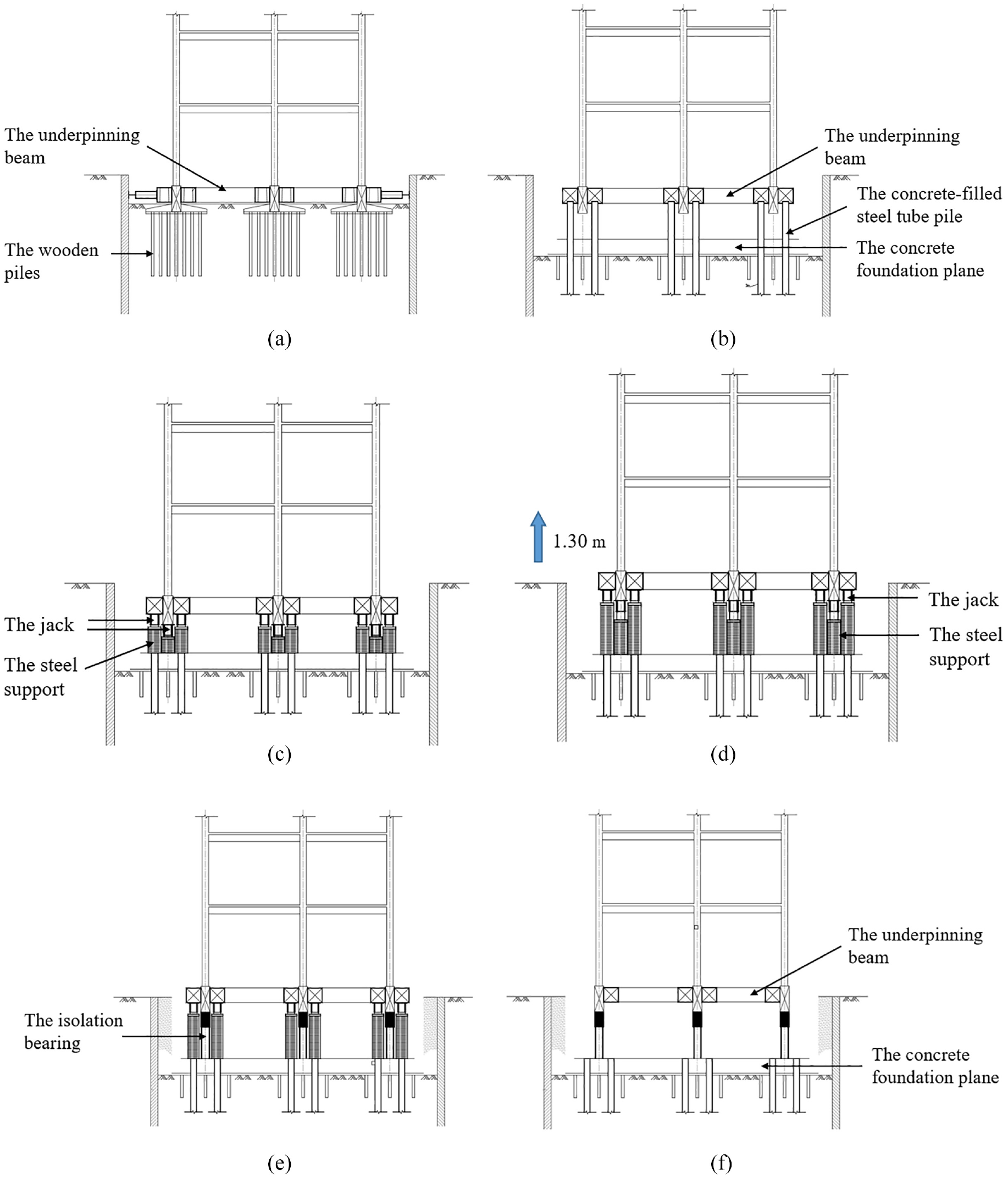
Construction scheme used to uplift Huadong Hospital’s south building: (a) Underpinning beam construction and earth excavation, (b) construction of concrete foundation plane and concrete-filled steel tube pile, (c) jacks were installed between the underpinning beam and foundation plane, and the piles were cut off, (d) the building was lifted by 1.30 m, (e) construction of isolation bearings, and (f) the earth is backfilled and jacks are retracted.
The uplifting of the building is currently the largest historic building uplifting project in terms of the construction area and building weight in China. In addition, as a Shanghai municipal heritage building, the south building of Huadong Hospital has some unique requirements in terms of historic building protection. The characteristics and demands of the project are as follows.
(1) The building is now a protected Shanghai municipal heritage building. There are many critical protection components with strict protection requirements, such as the exterior surface of the building, stairs, columns, and decoration at the top of the hall. Some weak components, such as arcades, must be reinforced and protected before uplifting. The building exterior surface crack width and settlement of the column must be controlled within a specific range to prevent damage. Other critical components with historical protection values should also be monitored to prevent cracks owing to excessive strain.
(2) A large number of jacks were used for the uplifting. The total weight of the south building was approximately 25,000 tons, the reinforced concrete underpinning beam was approximately 1900 tons, and the steel frame reinforcement device was approximately 155 tons. The overall building will be lifted by approximately 1.30 m using two groups of jacks alternately; the number of jacks is 484 sets for 200 tons jacks and 64 sets for 300 tons jacks.
(3) The structural plane is H-shaped, and the in-plane stiffness of the structure is significantly different. Therefore, it is necessary to control the inclination and differential settlement during the uplifting process of building to reduce the risks that may occur during uplifting.
Because the building may face many adverse conditions during the moving process, the uplifting project often requires stringent process control and structural health monitoring to minimize safety risks during the process. A total of 548 sets of jacks were used in this project. The jacks were divided into two groups, Groups A and B, with 274 jacks in each group. The layout of the jack is shown in Figure 5. When one group of jacks is working, the other group of jacks is raised with steel support to expand the uplifting range. Thus, the building can be alternately lifted by the two groups of jacks. The jack control system adopts a vertical displacement-pressure combined control system to ensure synchronous displacement accuracy and the safety of the building during the uplifting process. The displacement difference between each jacking point is often controlled within 3 mm, and the pressure of each jack is monitored simultaneously. When necessary, some of the jacks can be controlled by pressure to avoid situations whereby some adjacent jacks provide uneven support force. The jacks used to lift the building are shown in Figure 6.
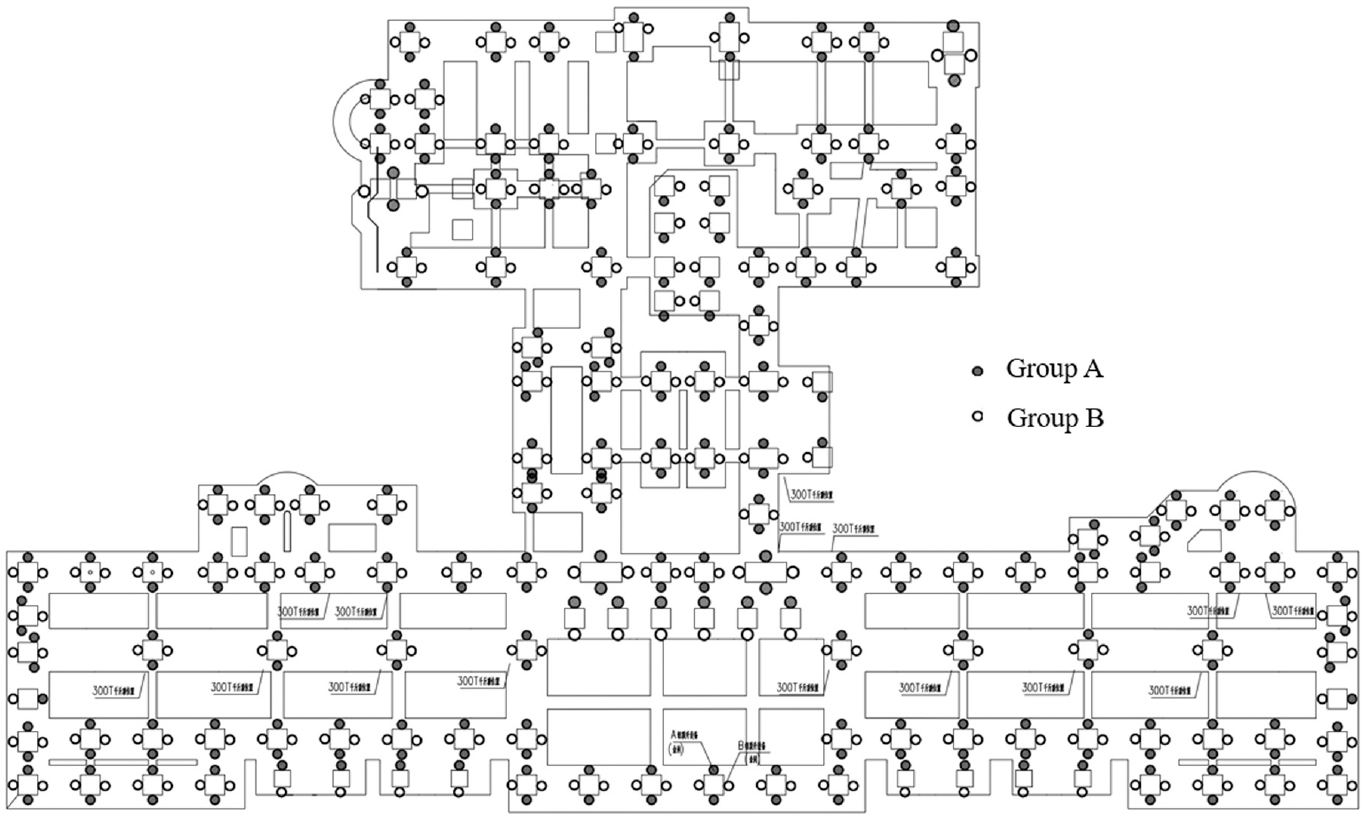
Layout of the two groups of jacks.
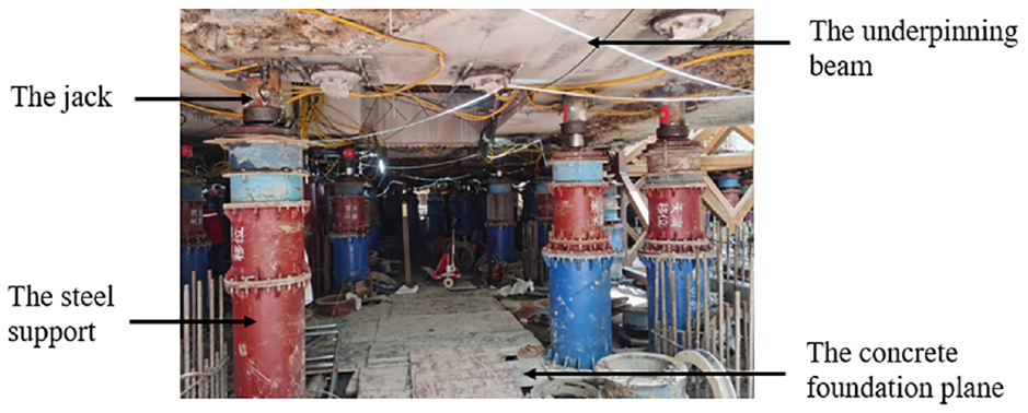
Jacks used to lift the building.
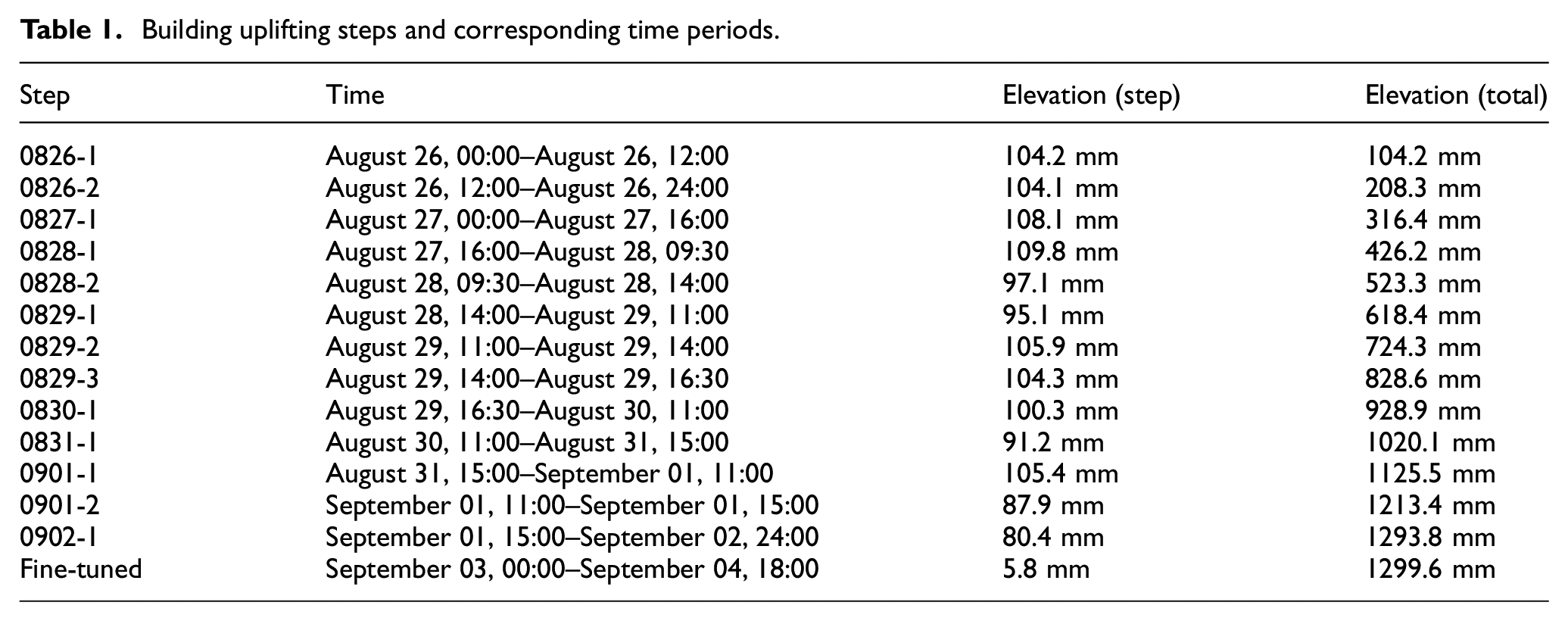
The uplifting process occurred from August 26 to September 04, 2021, and involved 13 lifting steps. The time periods corresponding to each step are listed in Table 1. Each step was approximately 0.10 m, and the total uplifting distance was 1.30 m. In addition, the uplifting distance of the building was fine-tuned on September 04, and the building finally reached the designated position. The building’s positions before and after uplifting are shown in Figure 7.
Building uplifting steps and corresponding time periods.
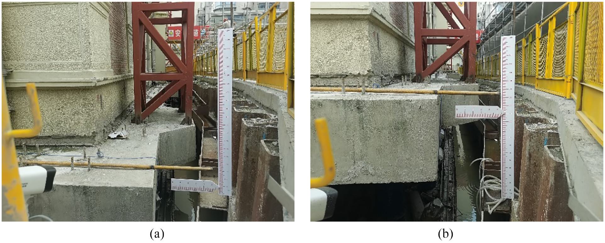
Building position before and after the uplifting: (a) Before uplifting, and (b) after uplifting.
Structural health monitoring system of the building
During the uplifting process, the structure may encounter many adverse conditions, such as excessive acceleration during the lifting process, unsynchronization of uplifting, or failure of some jacks. These adverse conditions may lead to differential settlement and overall inclination of the building or deformations and cracks in some critical components. Therefore, a structural health monitoring system was adopted to detect abnormalities in the structural condition and ensure the safety of the building throughout the process. The structural health monitoring of Huadong Hospital’s south building focuses mainly on the following aspects:
(1) Overall state monitoring of the structure, including vertical displacement monitoring, horizontal displacement monitoring, inclination monitoring of the building, differential settlement monitoring of the building, and acceleration during the uplifting process.
(2) Critical component condition monitoring, including crack monitoring and strain monitoring of vital components, such as the underpinning beam and building facades.
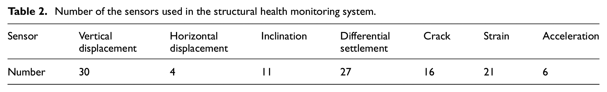
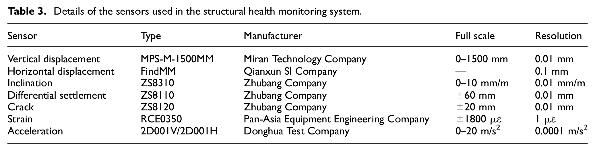
Table 2 shows the number of sensors used in the building’s structural health monitoring system, and Table 3 shows specifications of the sensors.31–34
Number of the sensors used in the structural health monitoring system.
Details of the sensors used in the structural health monitoring system.
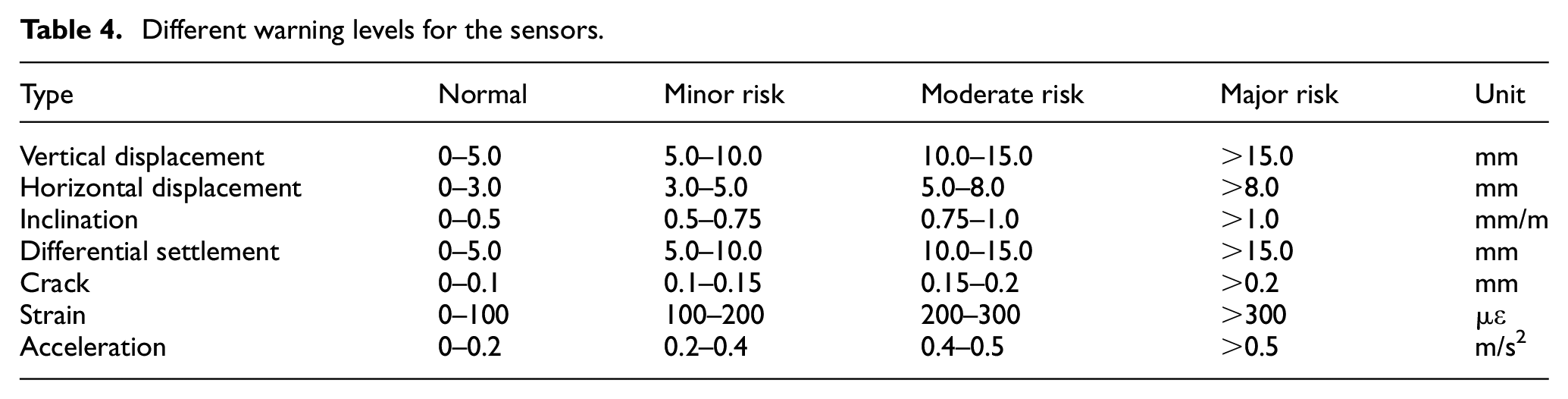
According to engineering code and engineering experience, there are different levels of warning values for structural displacement, inclination, cracks, and some other quantities that can reflect the state of the structure.35–39 When the warning value is exceeded, there is some risk to structural safety. In this building uplifting project, different warning levels were set (Table 4). It should be noted that the vertical displacement warning value is set for the vertical displacement differences between measurement points, and the horizontal displacement warning value is set for the actual horizontal displacement of the measurement points.
Different warning levels for the sensors.
Vertical displacement monitoring
The vertical displacement can directly reflect the uplifting process of a building. Thirty vertical displacement sensors were installed at the corners of the reinforced concrete underpinning beam, some jacking points, and the middle span of the beams. The sensors were numbered from LX-01 to LX-30, and the installation positions of the sensors are shown in Figure 8.
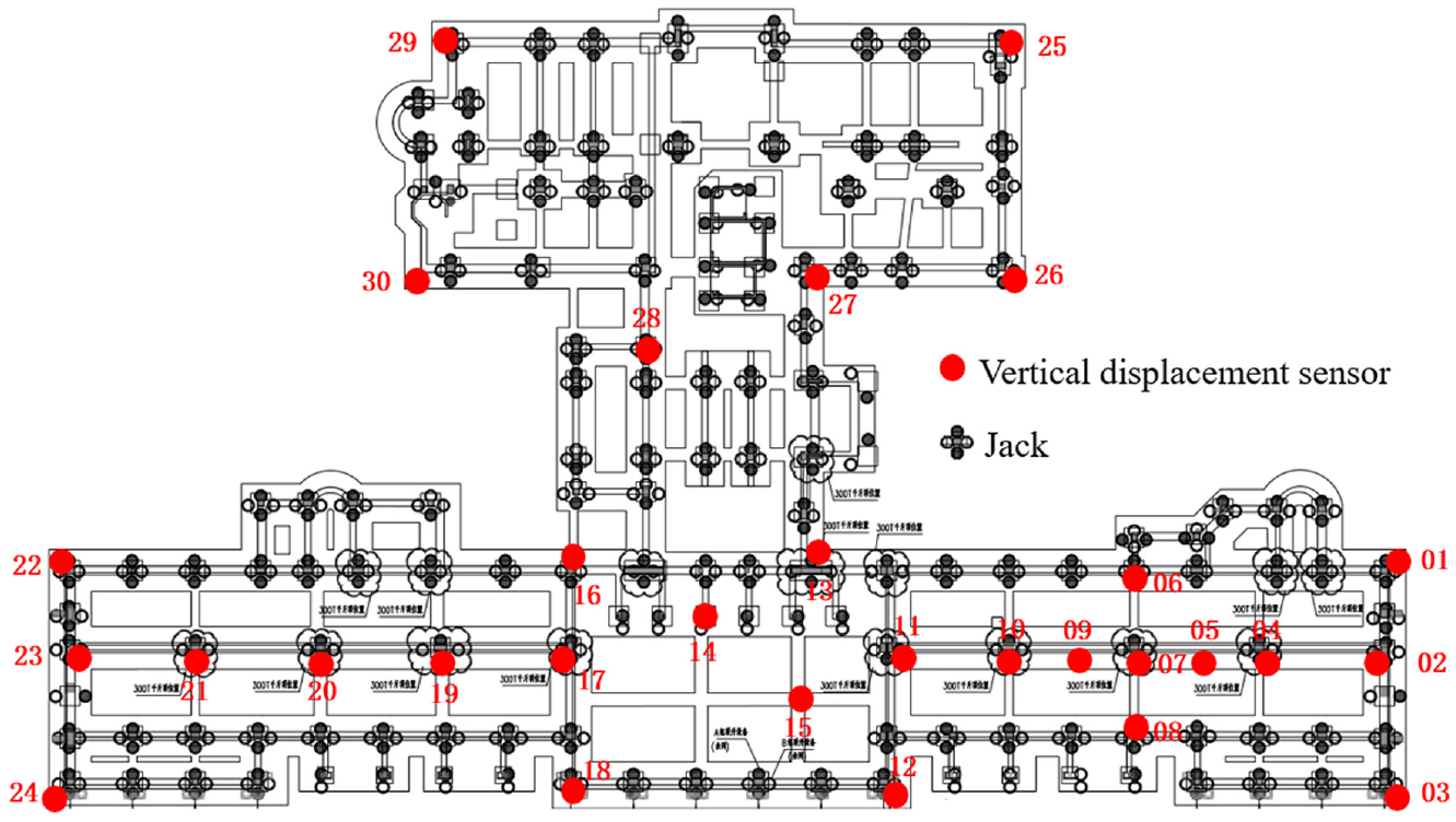
Installation positions of the vertical displacement sensors.
The vertical displacement sensors were wire-type displacement sensors, and they were fixed on the reinforced concrete underpinning beam (Figure 9). The wire of the sensor was connected to a steel frame fixed to a reinforced concrete foundation plane. When the jack lifts the underpinning beam, the displacement sensor can accurately measure the vertical displacement at each monitoring point. The installation diagram of the vertical displacement sensor and the photograph on site are shown in Figures 10 and 11, respectively.
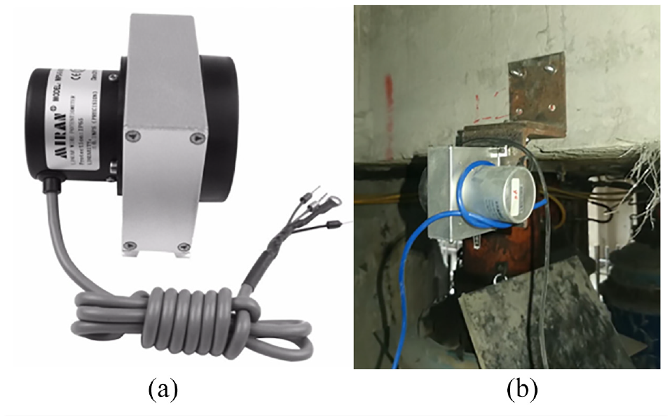
Vertical displacement sensor fixed on the underpinning beam: (a) vertical displacement sensors, and (b) installation photo.
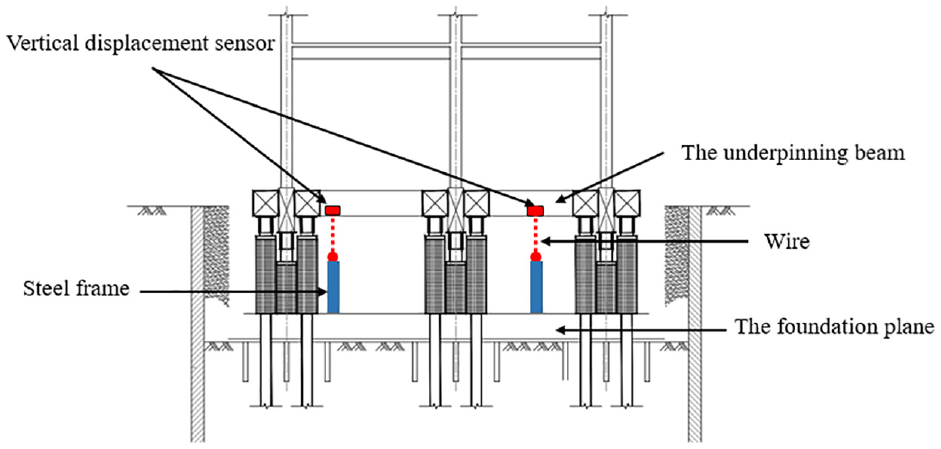
Installation diagram of the vertical displacement sensor.
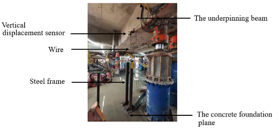
Photograph of the vertical displacement sensor and the steel frame on site.
Horizontal displacement monitoring
The horizontal displacement can directly reflect the deviation of the building in the horizontal direction during the uplifting process. The horizontal displacement sensor is based on global navigation satellite system and real-time kinematic technology, which enables millimeter-level horizontal positioning. 32 The sensor is composed of two components: a receiver and a base station. In the structural health monitoring system, four horizontal displacement sensors were used to measure the horizontal displacement at the corner of the building. Each horizontal displacement can monitor horizontal displacement in both east–west and north–south directions. Eight displacement directions are monitored. The monitoring points are numbered SP-01 to SP-04 (Figure 12).
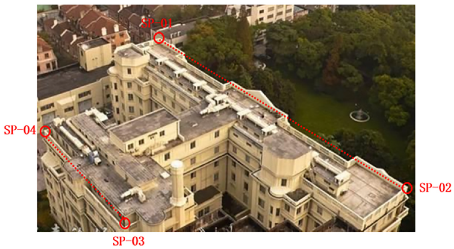
Installation positions for the horizontal displacement sensors.
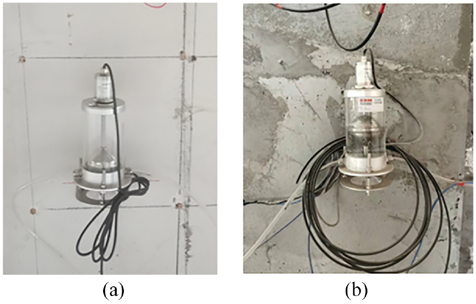
The receivers were fixed to the top roof of the building, while the base station was located on the roof of a nearby stable building. A photograph of the receivers and base station on the site is shown in Figure 13.
Photograph of the horizontal displacement sensor on site: (a) Receiver SP-02, (b) Receiver SP-04, and (c) base station.
Inclination monitoring
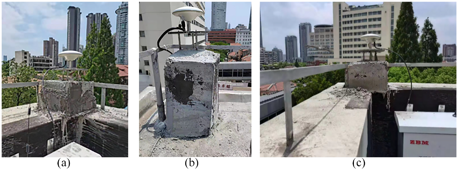
Building inclination reflects the overall posture during the uplifting process, which is critical for ensuring the safety of the building during uplifting. A total of 11 bidirectional inclination sensors, numbered from QX-01 to QX-11, were installed; the installation positions are illustrated in Figure 14. Inclination sensors were installed on the fifth floor of the outdoor wall. A photograph of the inclination sensor on the site is shown in Figure 15.
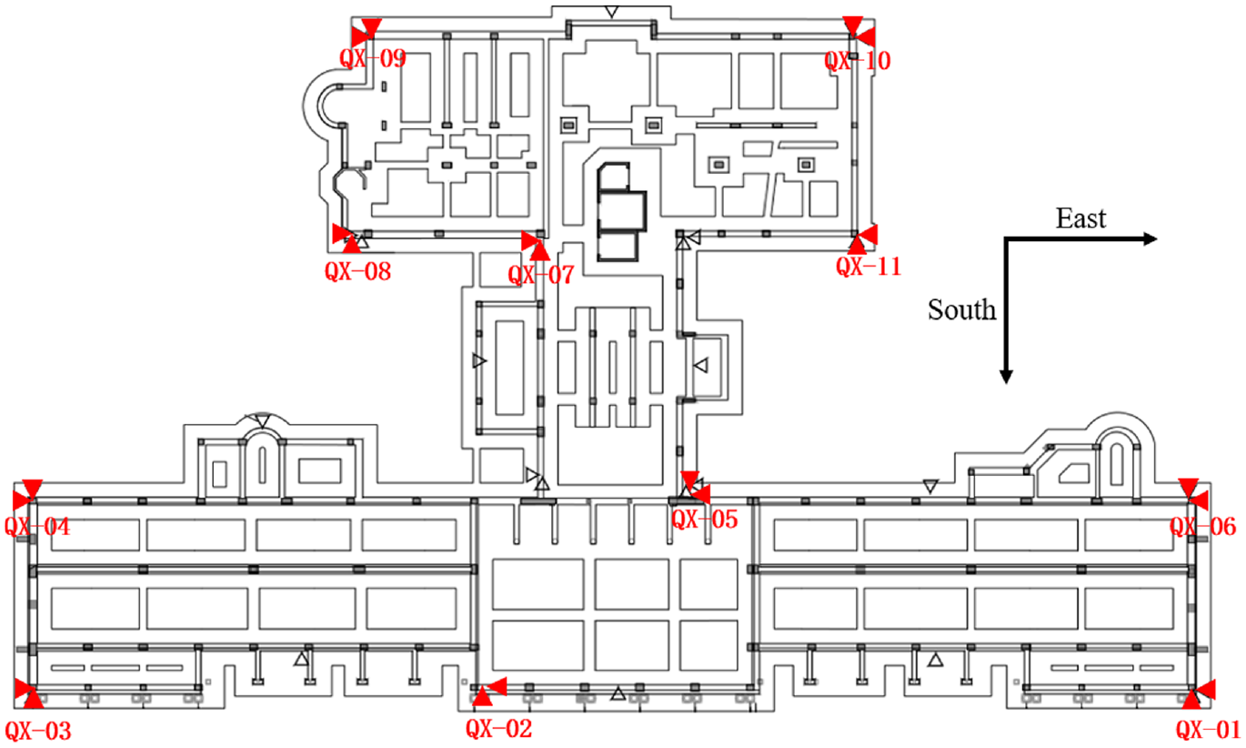
Installation positions of the inclination sensor.
Photograph of the inclination sensor on site: (a) QX-02 and (b) QX-11.
Differential settlement monitoring
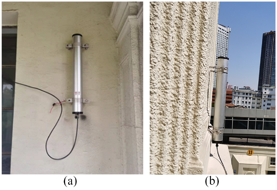
In this study, hydrostatic leveling sensors were used to monitor the differential settlement of the building. The differential settlement between each monitoring point and the reference point was measured based on the liquid level change during the uplifting process. Hydrostatic leveling sensors should be connected in series with water pipes. If there are too many sensors in series and the water pipe is too long, the monitoring error of the sensors increases. Two water pipes were connected to the hydrostatic leveling sensors because the number of measurement points was large in this project. Thus, two reference points are required when monitoring the differential settlement. A total of 27 differential settlement sensors, numbered from CJ-01 to CJ-27, were located on the second floor of the building (Figure 16), where CJ-03 and CJ-27 are the reference points connected to different water pipes. A photograph of the differential settlement sensor on site is shown in Figure 17.
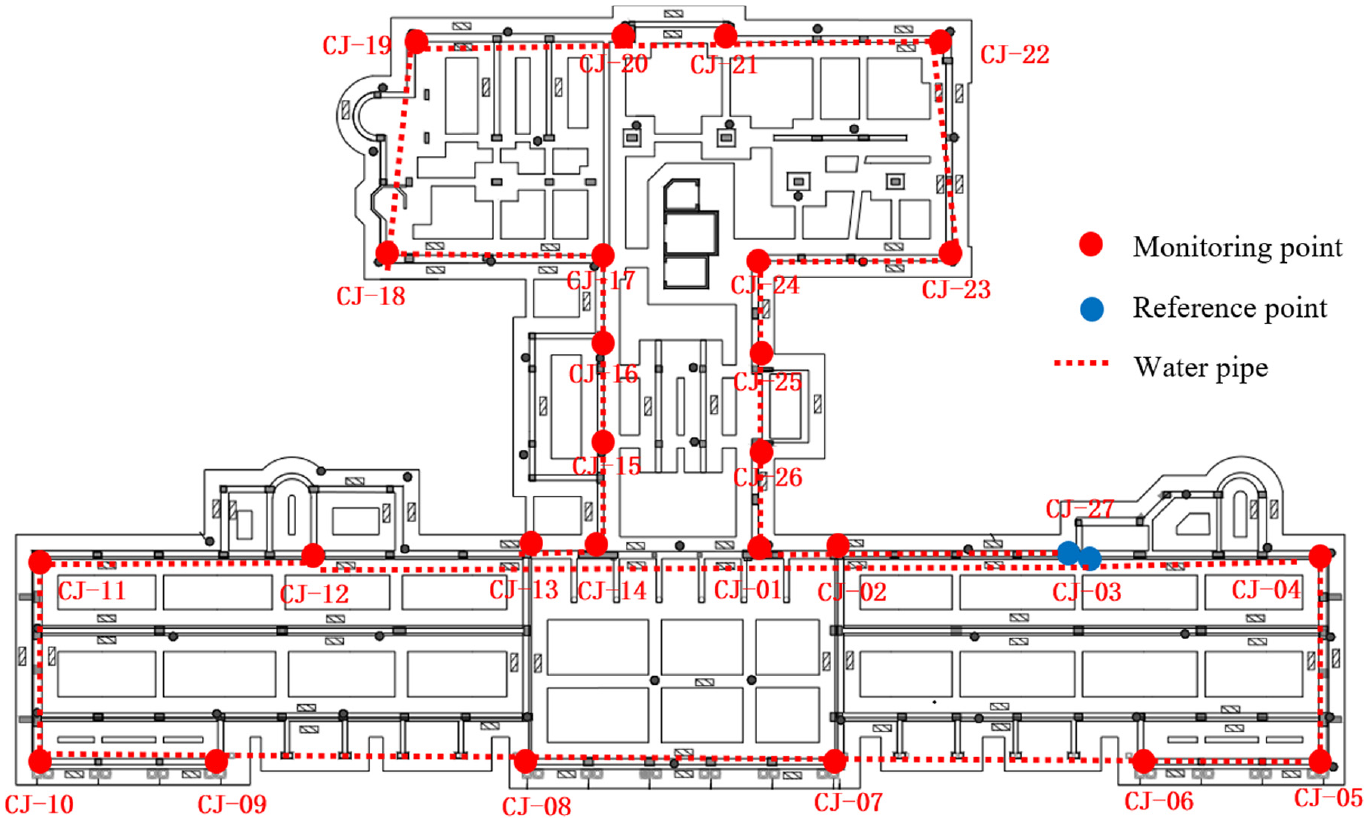
Installation positions of the differential settlement sensors.
Differential settlement sensor on site:(a) CJ-21 and (b) CJ-06.
Crack monitoring
During the uplifting process of a building, the weak parts of the structure are prone to cracks and extensions. Thus, it is necessary to monitor cracks in the critical components of a building. Sixteen crack sensors were used in the structural health monitoring system. The installation positions of the crack sensors included cracks in the facade of the building, cracks in the arch and pillar, cracks in the beam, and cracks in the temperature joint of the building. Photographs of the crack sensors are shown in Figure 18.
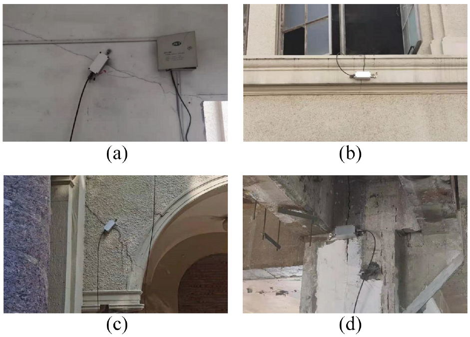
Crack sensors on site: (a) Crack in the wall(LF-01), (b) crack in facade (LF-02), (c) crack in arch (LF-05),and (d) crack in the temperature joint (LF-07).
Strain monitoring
The local stress and strain of the underpinning beam should be monitored to ensure that they do not exceed the threshold warning value during the uplifting process. The structural health monitoring system used 15 vibrating string-type reinforcement strain sensors and 15 concrete strain sensors to monitor the reinforcement strain and concrete surface strain, respectively. The sensors were placed in some middle-span positions and at the end of the beam (Figure 19).
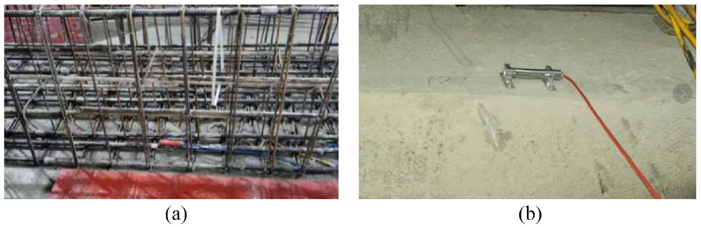
Reinforcement and concrete strain sensors: (a) reinforcement strain sensor, and (b) concrete strain sensor.
Acceleration monitoring
Six accelerometers were installed on the underpinning beam to prevent excessive acceleration of the structure at the start, end, and throughout the uplifting procedure. Four of the accelerometers were used to monitor the vertical acceleration, and the other two were used to monitor the acceleration in two horizontal directions (Figure 20).
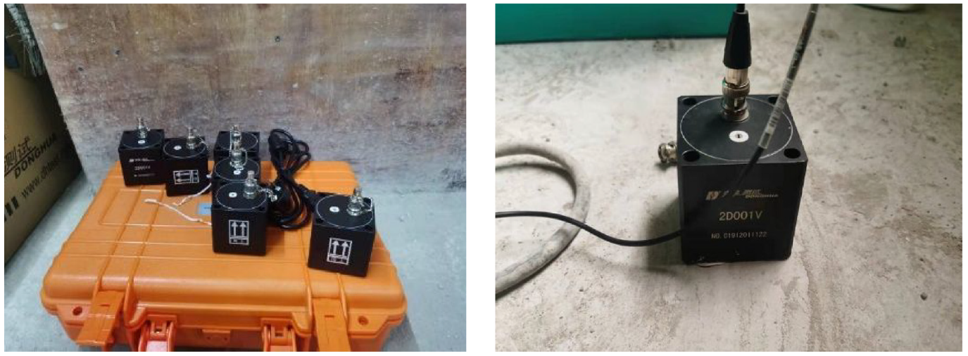
Accelerometers on site.
Composition of structural health monitoring system
The structural health monitoring system of the building consists of a sensor system, a data acquisition and transmission system, and a data management system. The composition of the structural health monitoring system is shown in Figure 21. The sensor system, which contains many different types of sensors, has been previously described. The sensors were connected to the data acquisition and transmission system, which receives the sensor’s signal and transmits the data to the Internet over a 4G transmission module. Twelve data acquisition and transmission boxes were used in the structural health monitoring system; each box was connected to 16 sensors through signal cables.
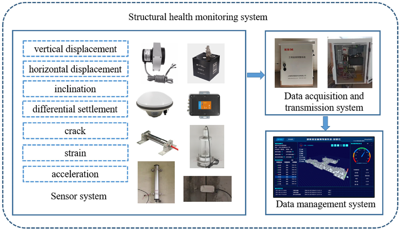
Composition of the structural health monitoring system.
The data management system can store and display the monitoring data, and can send warning messages according to the warning value threshold settings. Figure 22 shows the webpage of the monitoring data management system.
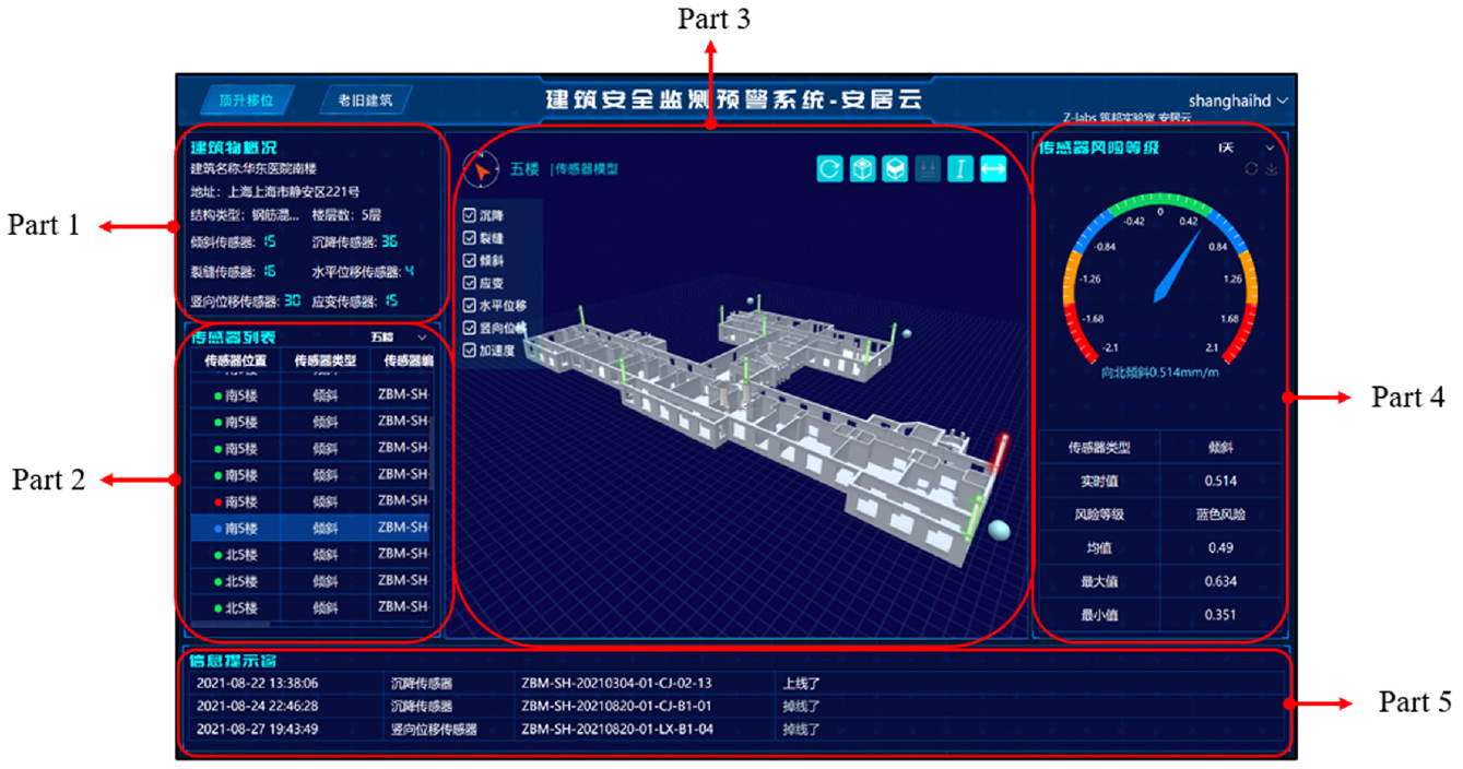
Webpage of the monitoring data management system.
There are five parts of the monitoring data management system webpage. Part 1 is the “Structural Health Monitoring System Overview,” which presents the basic information of the structural health monitoring system, such as the building overview, the types of sensors installed in the building, and the number of each type of sensor. Part 2 is the “Sensor Information List,” which displays the serial number, installation position, sensor manufacturer, sensor range, and other information for each sensor. When selecting a sensor serial number in Part 2, the corresponding sensor lights up in the building model, allowing us to determine the exact installation position of the sensor. The building model is shown in Part 3, and each layer of the building model can be selected to view the sensor positions. The real-time monitoring data of the selected sensor are shown in Part 4, where the four different colors of the warning board show the risk level of the selected sensor. Green indicates that the monitoring data are normal, and blue and orange indicate that the monitoring data are of minor or moderate risk, respectively. When the color turns red, it indicates that the monitoring data at the sensor position is a major risk and requires attention. In Part 4, the mean, maximum, and minimum values of the selected sensor data over a period of time are viewed, and the time history curve of the monitoring data can be downloaded for further analysis. Part 5 is the “Information Display Window,” which can display the warning information of the sensors when the monitoring data of the sensors trigger a warning signal. Furthermore, when some sensors go offline, there will be information alerts so that sensors can be repaired in a timely manner.
Analysis based on the monitoring data
Different sensors have been adopted in structural health monitoring system to allow the appropriate tracking of structural behavior. This section focuses on the monitoring data obtained during the uplifting process of the building, as well as an analysis of the data.
Vertical displacement monitoring data
The monitoring data of the vertical displacement sensor during the uplifting process are shown in Figure 23 (using sensor LX-15 as an example). The data of the first two uplifting steps on August 26 were lost because of sensor failure. The other 11 lifting steps can be observed from the vertical displacement monitoring data. Minor adjustments made to the jacks to guarantee synchronous lifting can also be displayed.
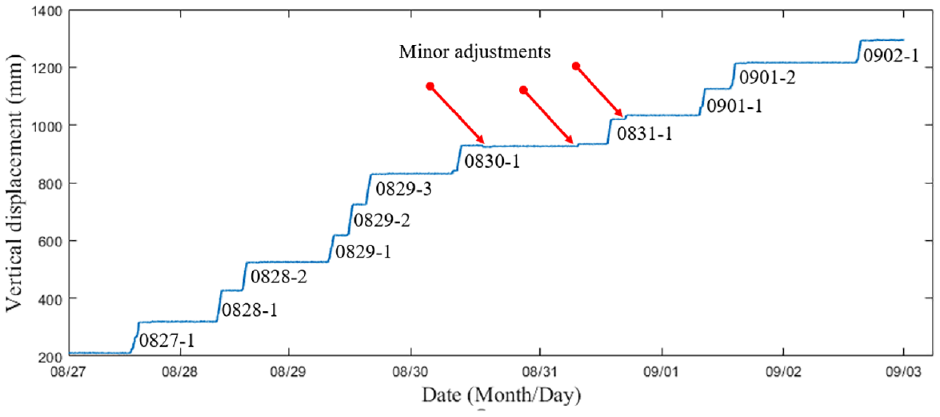
Monitoring data of the vertical displacement sensor LX-15.
The building was lifted three times on August 29. Therefore, the monitoring data of each vertical displacement sensor on August 29 were selected as typical lifting circumstances (Figure 24). Evidently, the uplifting at all vertical displacement sensor installation positions is basically synchronous; the maximum differential vertical displacement between the positions is approximately 15 mm. Because the positions with a significant vertical displacement difference are not adjacent and are far away from each other, they do not have a significant effect on the building’s overall posture and local state.
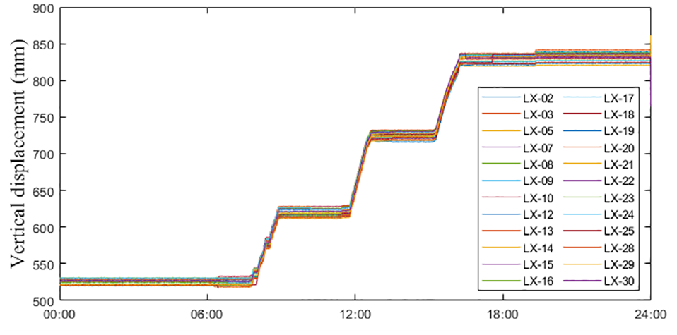
Monitoring data of each vertical displacement sensor (August 29).
The building’s ultimate average uplifting distance was 1299.56 mm, according to the data obtained from the vertical displacement sensor. Among the monitoring points, LX-05 and LX-11 had a low vertical displacement of approximately 1290 mm, whereas LX-20 had a large vertical displacement of 1306 mm. The difference in the maximum vertical displacement was approximately 16 mm. At the end of the 0831-1 lifting step, the west side of the main building was higher than the east, while the north side of the sub-building was higher and the south side was lower. In the subsequent lifting steps, this phenomenon gradually improved, and eventually the uplift became more uniform. The differential vertical displacement of the building was maintained within a safe range.
Horizontal displacement monitoring data
The monitoring data from the horizontal displacement sensor are shown in Figure 25. According to the monitoring data, the horizontal displacement of the building was within a safe range during the uplifting process. The maximum horizontal displacement occurred at the end of the 0831-1 lifting step. The roof of the building had a southward horizontal displacement because the northern side of the building was lifted slightly higher than the southern side. The west side of the main building also experienced higher uplifting, resulting in the east horizontal displacement of the building. The building slopes slightly to the southeast. After the subsequent lifting steps and minor adjustments, the horizontal displacement of the building partially recovered. Finally, the horizontal displacements of SP-01 to SP-04 in the east direction were 4.8, 6.2, 4.3, and 3.8 mm, respectively. The northward horizontal displacements were −0.8, −5.2, −3.0, and −4.2 mm, respectively. The ultimate horizontal displacement of the building in each direction was less than 8 mm, which is less than the warning value.
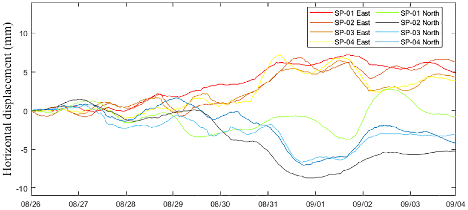
Monitoring data of the horizontal displacement sensors.
The inclination monitoring data
According to the inclination monitoring data, most of the monitoring points in the main building tilted to the east and south slightly during the uplifting process, and the sub-building also showed a slight eastward and southward inclination, except for QX-11. The trend of building inclination was consistent with differential uplifting. The maximum inclination of roughly 0.5 mm/m occurred after the 0831-1 lifting step. After the adjustment in the subsequent lifting steps, the inclination of the building was partially recovered. The major risk warning value of the building was 1 mm/m, and the monitoring data of all inclination sensors were within the safe range during the uplifting process. Figures 26 and 27 show the inclination of the building after the 0831-1 and 0902-1 lifting steps.
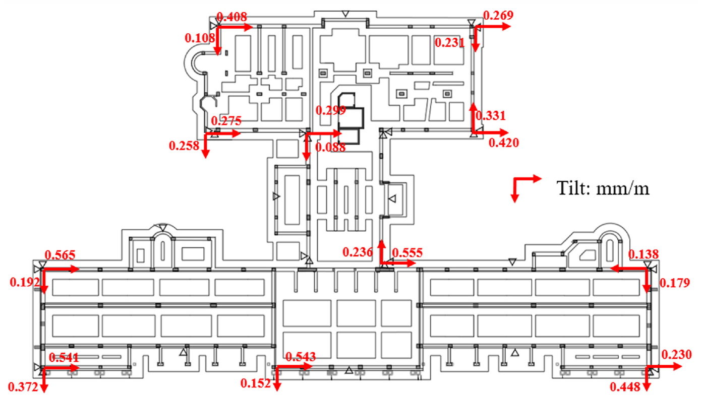
Monitoring data of the inclination sensors (after the 0831-1 lifting step).
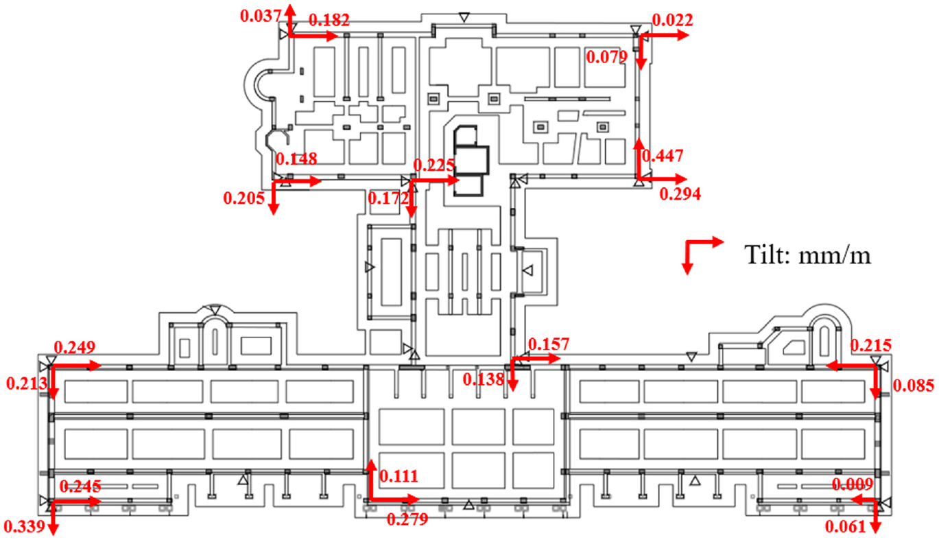
Monitoring data of the inclination sensors (after the 0902-1 lifting step).
Differential settlement monitoring data
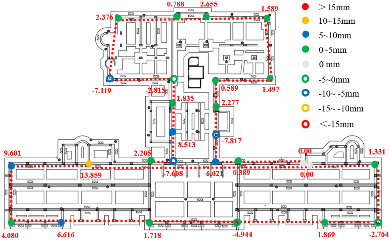
The monitoring data from the differential settlement sensors showed that the west side of the main building was slightly higher. The monitoring points CJ-11 and CJ-12 at the northwest corner of the main building increased by approximately 10 mm compared with the reference point, which was one of the reasons for which the overall posture of the main building tilted to the southeast. The monitoring points at the southwest corner of the sub-building dropped by approximately 7 mm compared with the reference point, whereas the monitoring points on the north side had no evident settlement. In addition, the settlement at the monitoring points near the stairwell was significant, with a settlement of approximately 12 mm. The differential settlement monitoring data after the 0831-1 and 0902-1 lifting steps are shown in Figures 28 and 29, respectively. During the uplifting period, most of the differential settlement data remained within the safe range; however, the data from several monitoring points exceeded the major risk warning value. Considering that some hydrostatic leveling sensors were affected by indoor construction on August 26 and 27, the differential settlement monitoring data did not trigger the warning.
Monitoring data of the differential settlement sensors (after the 0831-1 lifting step).
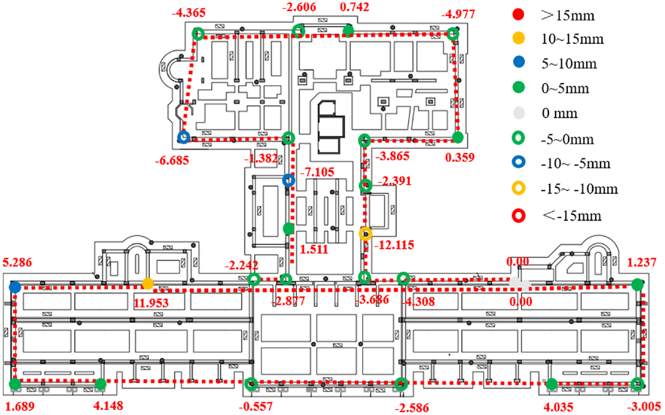
Monitoring data of the differential settlement sensors (after the 0902-1 lifting step).
During the uplifting process, the monitoring data for the vertical displacement and differential settlement were in good agreement. For example, after the 0831-1 lifting step, the vertical displacement monitoring data show that the west side of the main building is higher than the east, while the north side of the sub-building is higher, and the south side is lower. Differential settlement monitoring data showed similar results. After the 0902-1 lifting step, the vertical displacement monitoring data showed that the northwest corner of the main building was 8.9 mm higher than the southeast corner, and the differential settlement monitoring data showed that the difference between the two points was 8.3 mm. The different types of monitoring data in the monitoring system exhibited a high degree of consistency.
Crack monitoring data
The monitoring data for the crack sensors are shown in Figure 30. According to the crack monitoring data, the cracks in the building did not expand significantly during the uplifting process. The crack variation in most of the monitoring points was less than 0.2 mm; the variation in the crack width did not exceed the major risk warning threshold value. Furthermore, because the cracks can be affected by temperature fluctuations, some of the cracks repeatedly shrink and expand as the temperature varies, particularly some outdoor structural cracks where the temperature difference between day and night is significant. The temperature-induced crack width variation was similar to that of the temperature-expansion joints. When the temperature is higher during the day, the concrete expands, making the cracks smaller, and when the temperature is lower at night, the concrete contracts, resulting in larger cracks. Crack sensors fixed on both sides of the crack can accurately monitor crack width expansion and contraction under temperature changes. The monitoring results also show that on cloudy and rainy days with little temperature difference between day and night, the expansion and contraction of cracks are not obvious, whereas on some sunny days with large temperature differences between day and night, there are significant changes in the crack width between day and night.
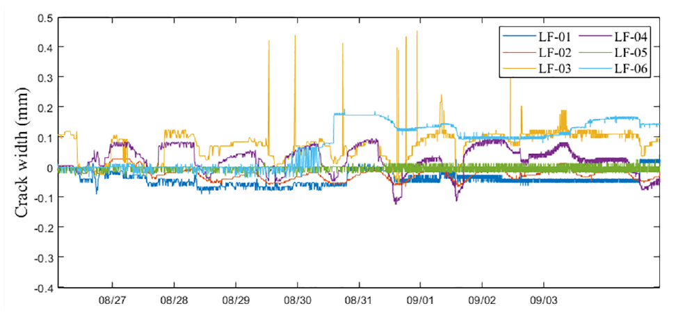
Monitoring data of the crack sensors(LF-01–LF-06).
Strain monitoring data
During the uplifting process of the building, some strain sensors failed to obtain effective data because of the failure of the data acquisition box. The maximum strain of each online sensor during the uplifting process is shown in Figure 31. For all of the online strain sensors, the data did not exceed the major risk warning value.
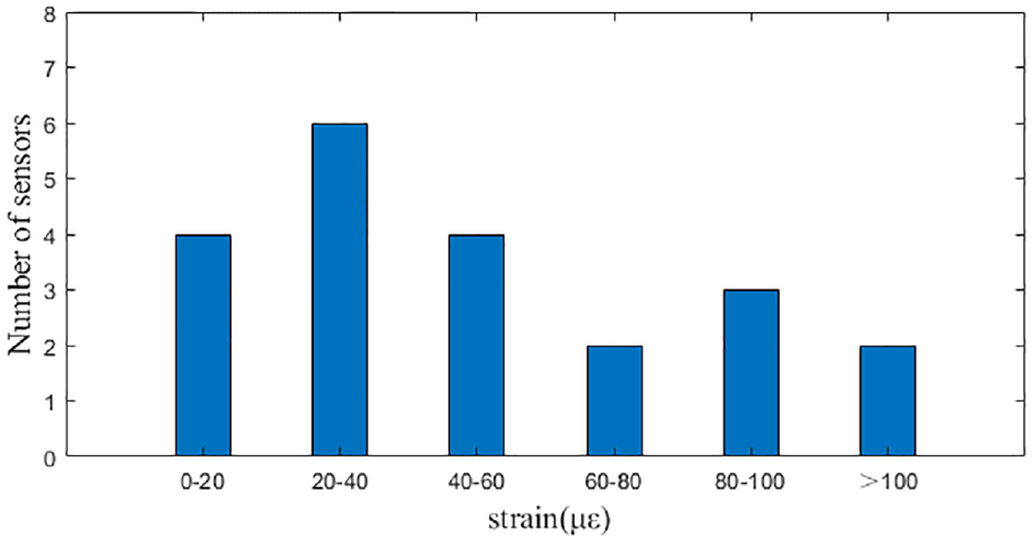
Maximum strain of each strain sensor during the uplifting process.
Acceleration monitoring data
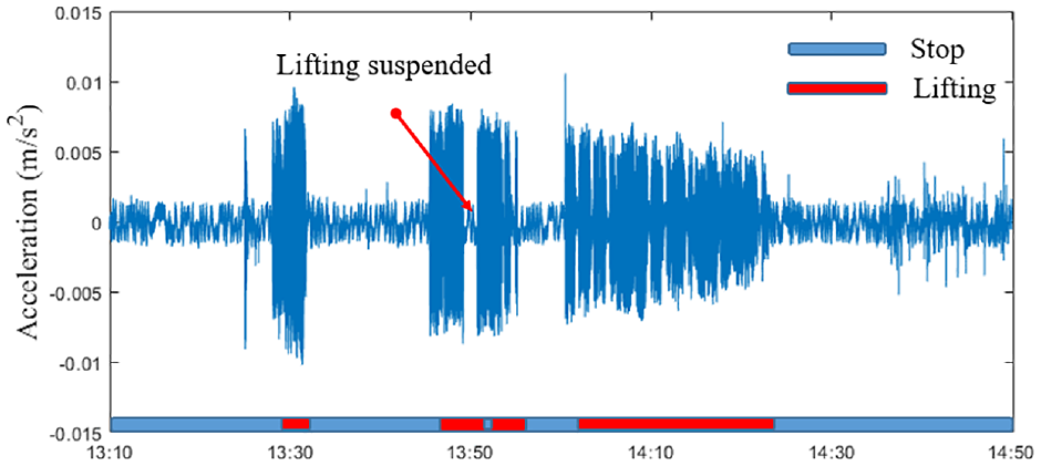
The typical acceleration time-history curve of the building is shown in Figure 32 (taking accelerometer No. 02 as an example, the monitoring data selected the 0901-2 lifting step, from 13:10 to 14:50 on September 1).
Monitoring data of the acceleration sensor(No. 02).
Figure 33 shows the monitoring data of vertical displacement sensor LX-15 during the 0901-2 lifting step. When lifting starts, stops, and is suspended, a significant acceleration change can be observed (Figure 32). There are many reasons for the suspension during the uplifting process: for example, the jacks are not functional, damage to the hydraulic hose, the need for the jacks to be adjusted in the case of uneven vertical jacking, or some abnormal monitoring data triggering a warning to cause the uplifting to be suspended. Figures 32 and 33 show that the uplifting suspended during the uplifting process at approximately 13:50, and the main reason for this suspension was the need to make a slight adjustment to the jacks. The acceleration time-history curve corresponded well with the lifting situation of the building. During the uplifting process, the building’s peak acceleration was within 0.02 m/s 2 , except for some local vibrations affected by the construction.
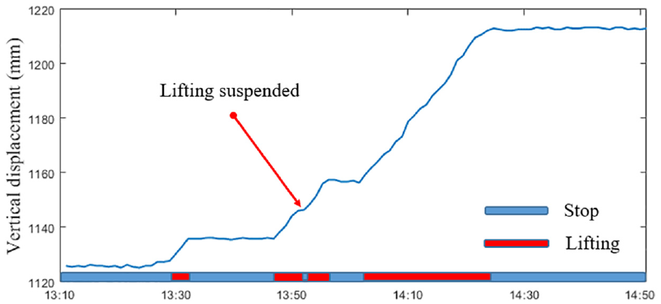
Monitoring data of the vertical displacement sensor (LX-15).
The monitoring data of the vertical displacement, horizontal displacement, inclination, differential settlement, crack, strain, and acceleration indicate that the building was safe most of the time during the uplifting process. However, at some time points during uplifting, some monitoring data samples show that the building is at risk owing to uneven uplifting, and the corresponding safety level assessment is shown in the following section. Although the overall building tilted slightly to the southeast during the lifting process owing to the differential vertical displacement, the situation was remedied in subsequent lifting steps. Most of the monitoring data were within the safety range. The building was also inspected on site. No obvious structural cracks were observed in the building or underpinning beam, proving that the structure was safe during uplifting.
Structural safety assessment based on data-driven neural networks
The assessment of structural safety levels based on different threshold warning values still has some problems and limitations. For example, outliers caused by the malfunctioning of some sensors and interference of the construction near the sensor installation location often lead to inaccurate assessment results. In addition, the local state of the structure may have little influence on the overall state of the structure, and judging the structural safety levels only based on the data of one or several sensors exceeding the warning values may lead to false alarm. 12 Therefore, a more effective approach is required to consider the structural safety levels in a more systematic and comprehensive manner.
In this section, a structural safety assessment based on neural networks and multisource monitoring data is presented. The mapping relation between the monitoring data and building safety level is complex and nonlinear. Furthermore, the overall posture and local settlement of the building are all important aspects when assessing the state of the structure, and these monitoring data often have spatial correlation. In particular, in this project, the monitoring data come from various types of sensors, and the monitoring data are multi-source and correlated. Neural networks have strong fitting and generalization abilities; they can acquire knowledge by training with adequate datasets.40–42 Therefore, a reliable structural state can be obtained through the neural networks and reflected in the data of the hidden layer, realizing the processing of multi-source monitoring data and the assessment of structural safety levels. 43
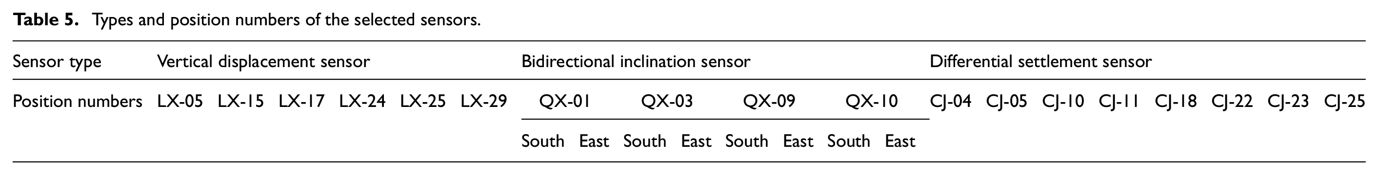
Before using neural network training, it is necessary to select the appropriate monitoring data and preprocess the data. The monitoring data of some important sensor positions at specific points in time were selected as the input, and sampling was conducted every 15 min from August 27, 00:00 to September 3, 24:00, with a total of 769 samples. Because selecting more sensors will result in a significant increase in the number of samples required for training the neural networks, only some sensors at important monitoring positions, such as corner points of main buildings and sub-buildings, were selected. The selected sensors include six vertical displacement sensors LX-02, LX-15, LX-17, LX-24, LX-25, and LX-29; four bidirectional inclination sensors QX-01, QX-03, QX-09, and QX-10; and eight differential settlement sensors CJ-04, CJ-05, CJ-10, CJ-11, CJ-18, CJ-22, CJ-23, and CJ-25. The types and positions of the selected sensors are presented in Table 5. Before training, we normalized the monitoring data to improve the calculation efficiency and avoid a non-converging network.
Types and position numbers of the selected sensors.
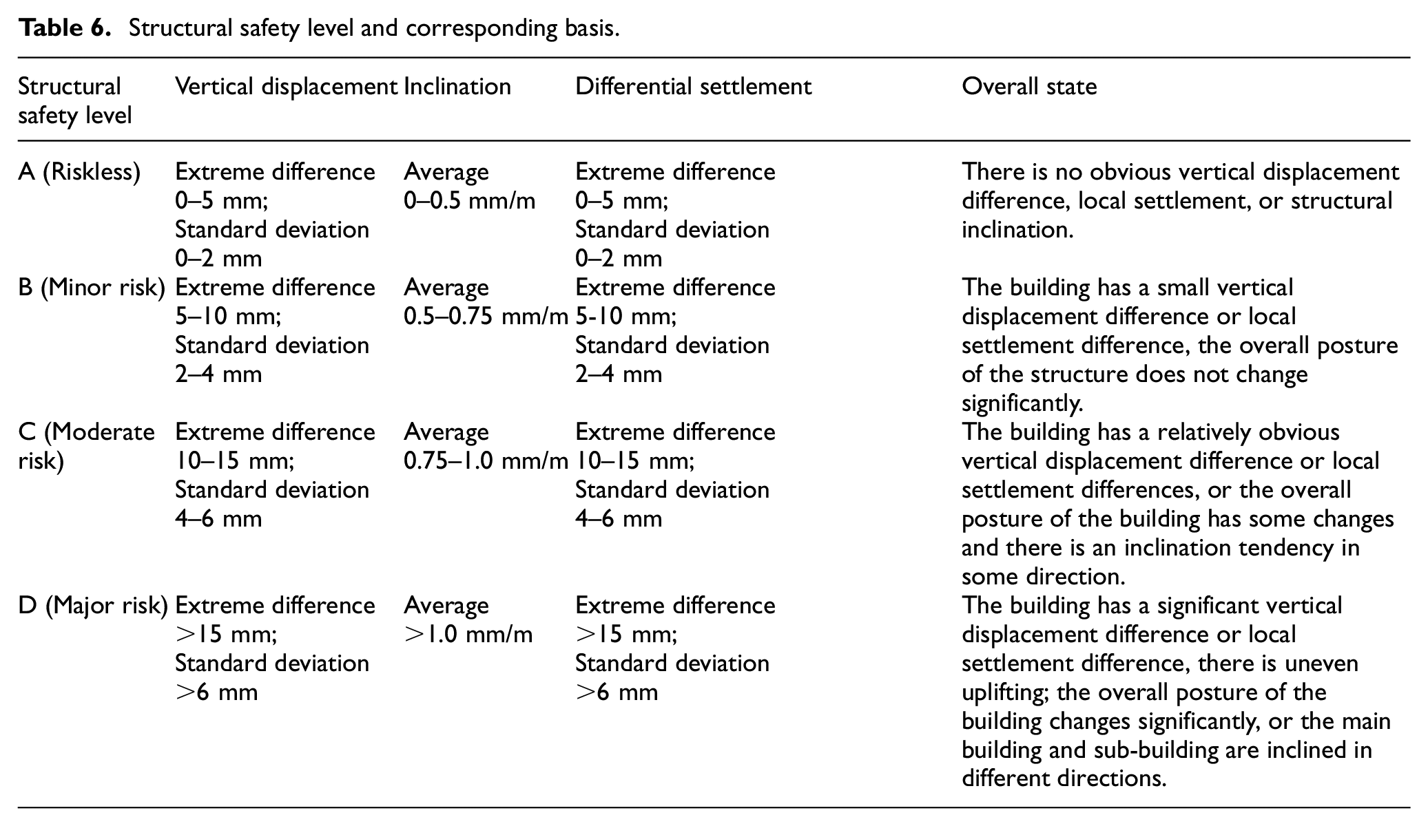
The output of the neural network has four levels of structural safety: level A indicates that the structure is completely riskless, level B indicates that the structure has minor risk, level C indicates that the structure has moderate risk, and level D indicates that the structure has major risk. The structural safety level assessment is mainly based on quantitative indicators and engineering experience. The corresponding basis is shown in Table 6. When the structural safety assessment level reaches level D, further inspection and evaluation of the structure are required to determine whether the warning should be triggered.
Structural safety level and corresponding basis.
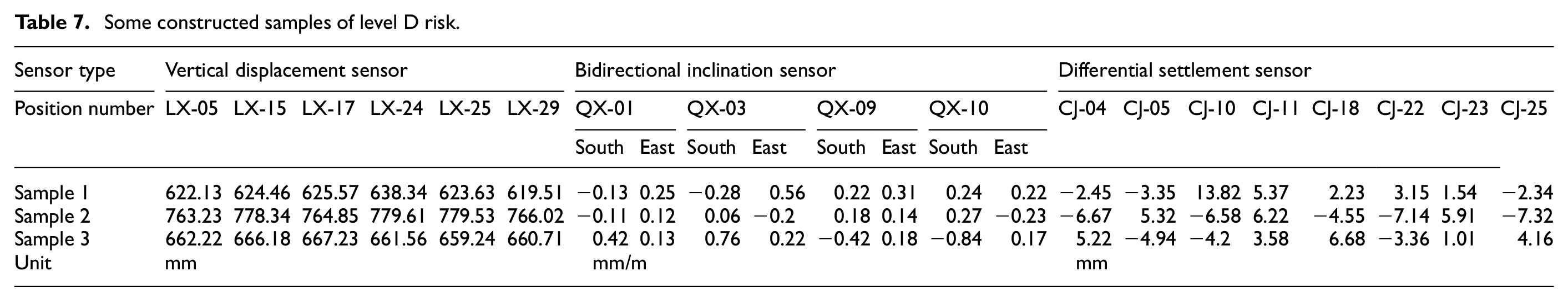
Because there were few samples of level D in the monitoring data, based on the existing monitoring data, we extrapolated and constructed some monitoring data samples corresponding to level D risk. Some constructed samples of level D risk are shown in Table 7 and mainly simulate the occurrence of major risk situations. These situations include significant vertical displacement differences or settlement differences, a large inclination in a given direction, or inclination of main building and sub-building in different directions. For example, the first sample in Table 7 is a level D risk because the vertical displacement difference and differential settlement are large; the southwest corner of the building is evidently higher than the average of the building. The second sample is a level D risk because, according to the vertical displacement and settlement data, the building is unevenly uplifted and the standard deviation of the vertical displacement is very large. For the third sample, the main building and sub-building are inclined in different directions, which also poses a major risk to buildings. These constructed data samples corresponding to level D risk are added to the training set so that the neural networks can be trained to identify some major risk level monitoring data.
Some constructed samples of level D risk.
The training neural networks are shown in Figure 34. Three neural network models were used to assess the monitoring data while the single neural network model used in this project is suitable for binary classification. Thus, the model1 can be used to distinguish levels A and B from levels C and D. Subsequently, the classified monitoring data of levels A and B can be input into model2, and the classified monitoring data of levels C and D can be input into model3, to further distinguish the safety levels. Unlike that through a single neural network, structural safety level assessment through multiple neural network models can achieve higher accuracy. In this project, each model had one input layer, two hidden layers, and one output layer. The input layer had 22 neurons, the two hidden layers had 10 and 5 neurons, and the output layer had 1 neuron.
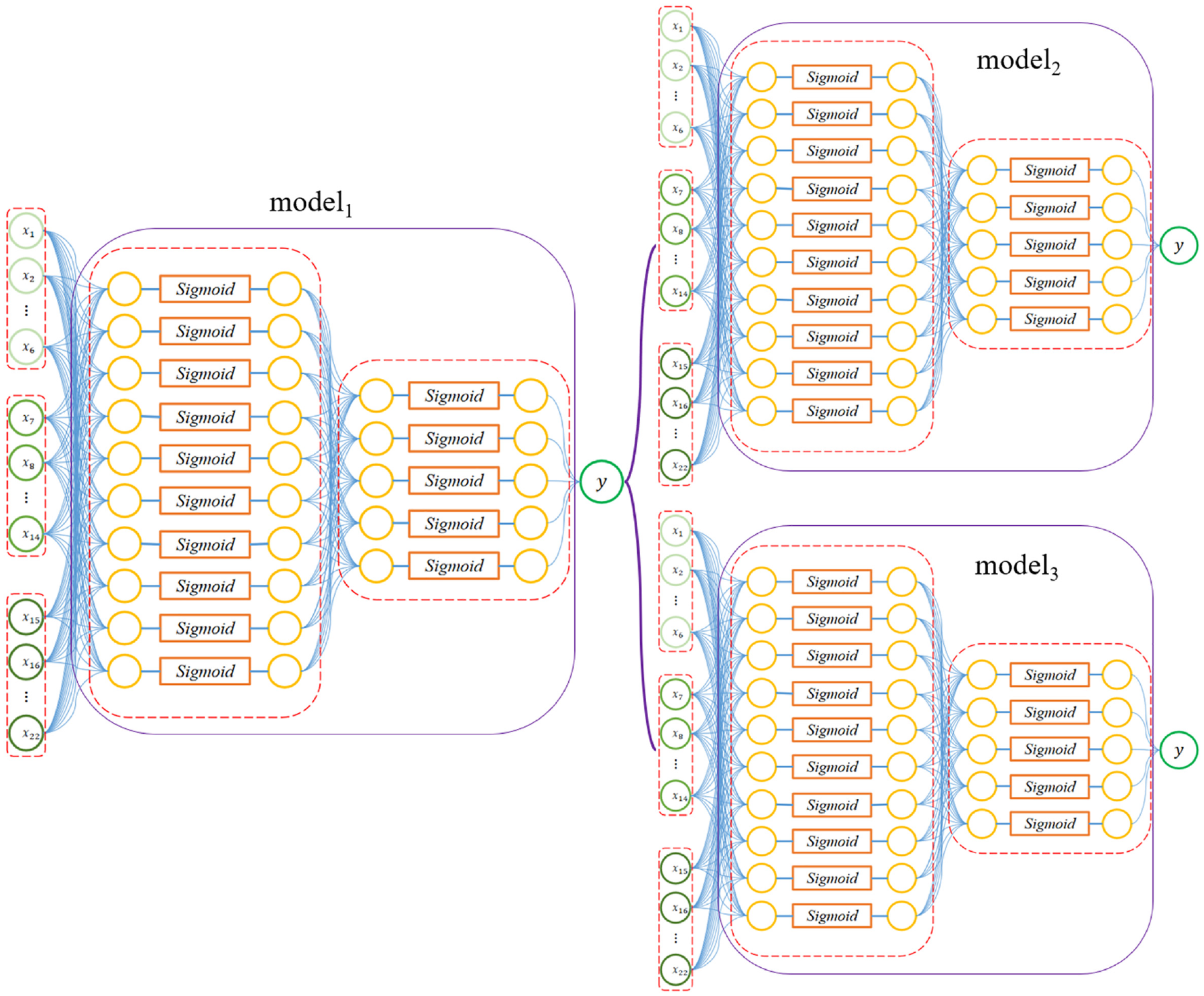
Neural networks for the structural safety assessment.
The Sigmoid function is selected as the activation function:
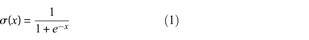
In the back-propagation steps, the binary cross-entropy (BCE) loss was used to measure the BCE between the target and output. For an input vector
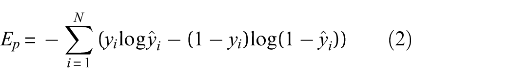
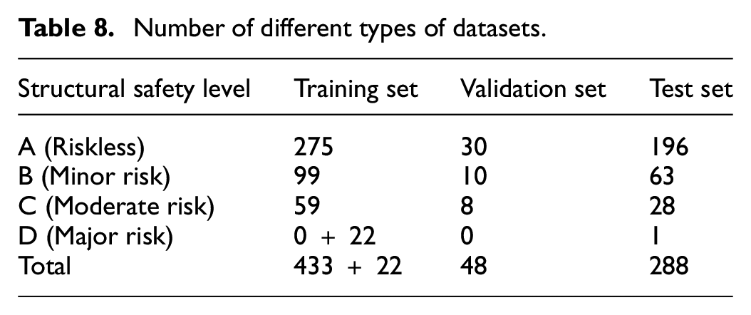
The process of assessing the data-driven neural networks is described briefly as follows. (1) First, the monitoring data were preprocessed, the data at some time points were selected into samples, and artificial assessment of building safety level is according to the basis of four levels, ranging from completely riskless to major risk. If major risk level samples are lacking, some artificially constructed monitoring data samples corresponding to this level are added. (2) A training dataset was established and labeled. Among the monitoring data samples, 433 samples were from August 27, 00:00, to August 31, 12:00. Meanwhile, 22 artificially constructed major risk-level samples were used as the training set. Neural networks were trained on the training dataset. (3) The 48 samples from August 31, 12:15, to August 31, 24:00, were selected as the validation set to verify whether the model overfitted during the training. (4) Finally, neural networks are used in the subsequent structural safety level assessment to avoid a cumbersome artificial assessment process. A total of 288 samples of data from September 1, 00:15, to September 3, 24:00, were selected as the test set to verify the feasibility of the trained neural networks when assessing the structural safety level. A flowchart of the assessment method based on data-driven neural networks and the number of different types of datasets are shown in Figure 35 and Table 8, respectively.
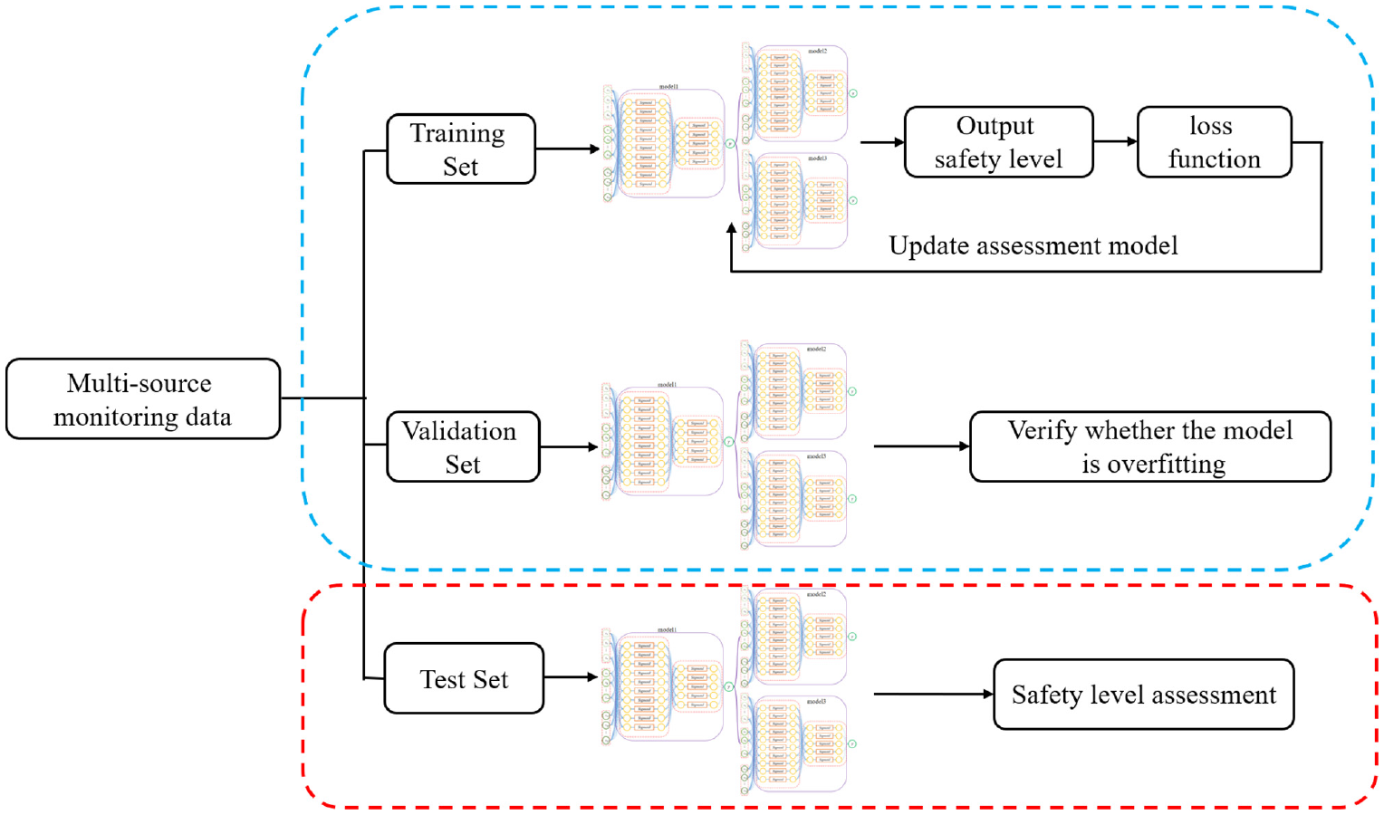
Flowchart of the assessment method based on monitoring data and neural networks.
Number of different types of datasets.
After trained on the training set, the test set was used to verify the feasibility of the neural networks to assess the structural safety level. The assessed values based on neural networks and the actual values based on artificial assessment were compared as follows (Table 9):
Structural safety assessment results: (a) validation and (b) test sets.
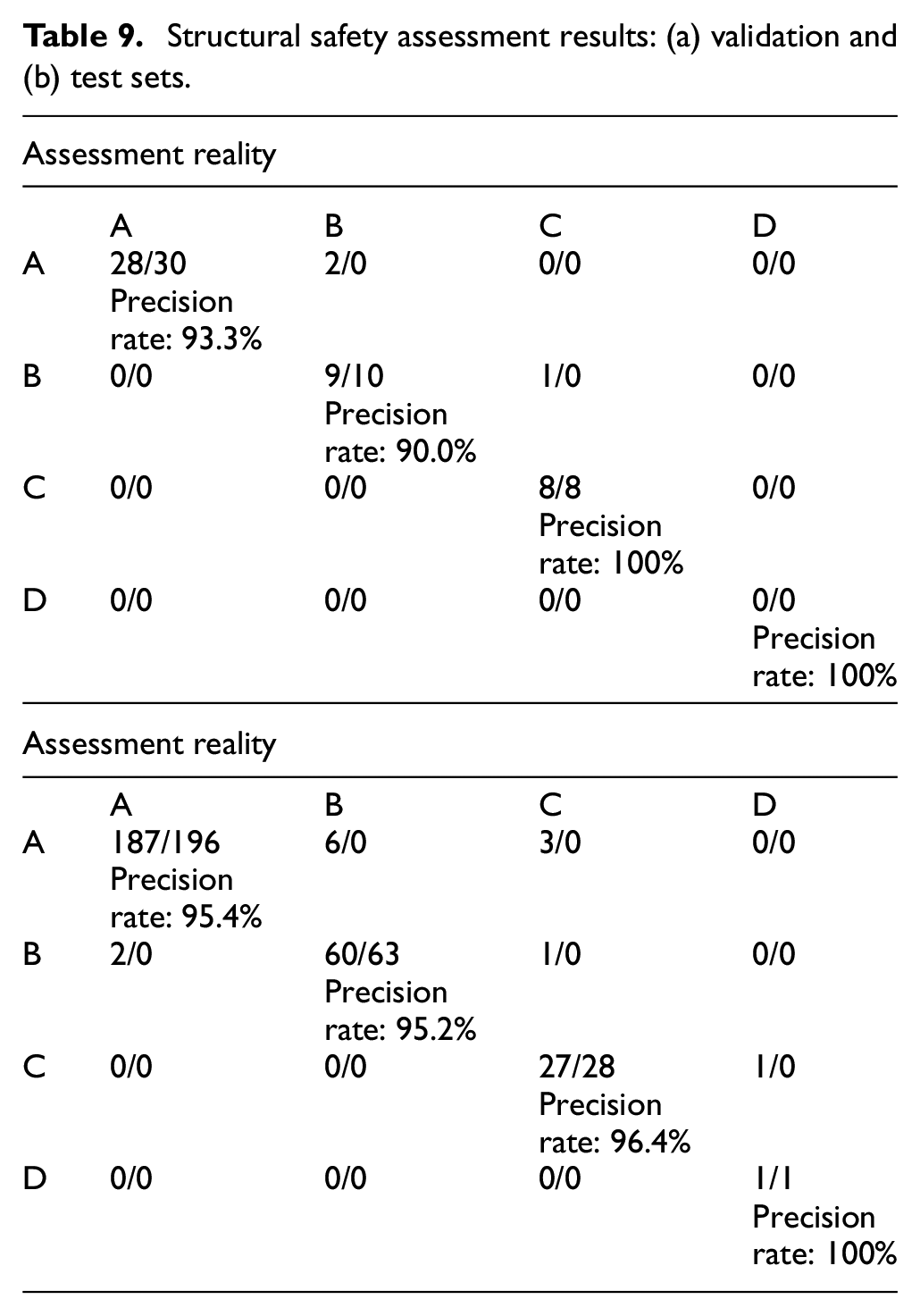
The results showed that the assessed structural safety level based on neural networks was mostly consistent with the actual values based on artificial assessment. In the training set, a sample of the level D risk was successfully identified during the uplifting process, where the sample was a major risk level case during the uplifting process with a vertical displacement difference exceeding 20 mm and a vertical displacement standard deviation of 7 mm. In general, the structural safety assessment results based on neural networks are accurate and can be used in the subsequent building uplifting process to prevent the occurrence of heavy artificial assessment workloads. Although there are still some false alarms and missing alarm samples, the average precision of the structural safety assessment based on neural networks reached approximately 90%. Some of the reasons for false alarms and missing alarms are that artificial assessment has some subjectivity and empirical judgment that neural networks may not be able to learn. If the samples in the training set are sufficient, these false and missing alarm samples can be further reduced. Furthermore, the complexity of neural networks can be increased, and monitoring data can be further preprocessed to improve the accuracy of the assessment.
Conclusions
The uplifting of a historic building can achieve a balance between retrofitting the building and protecting its historical and cultural values. The proposed structural health monitoring system aims to help evaluate the effect of uplifting on historic buildings and to ensure structural safety during the uplifting process. Based on the structural health monitoring system design and data analysis presented in this study, there were several experiences and conclusions, and these are as follows:
(1) The structural health monitoring system of Huadong Hospital’s south building comprises multiple sensors, a data acquisition system, and a data management system. The monitoring data can be automated, made available in real time, and networked, enabling a comprehensive and effective monitoring of building conditions. The proposed structural health monitoring system in this project provides a demonstration for the monitoring system of the uplifting building.
(2) The structural health monitoring of historic buildings during the uplifting process should focus more on the differential vertical displacement, which can easily change the stress state of the structure and cause large strains or cracks. In addition, during the entire uplifting process, there should be focus on the inclination of the building.
(3) Structural health monitoring systems often obtain a large amount of multi-source monitoring data. Some data, such as vertical displacement, horizontal displacement, and building inclination, are correlated. The use of multi-source data to assess the structural state in real time is an important issue in monitoring data analysis. In this regard, structural safety assessment based on neural networks is an effective method that can realize significant savings in the manual assessment workload.
(4) At present, most sensors in structural health monitoring systems still require wires to supply power and transmit signals, resulting in time-consuming and labor-intensive installation of monitoring systems. In future work, passive and wireless sensors should be used to make the structural health monitoring system more convenient and economical.
Footnotes
Declaration of conflicting interests
The authors declare no potential conflicts of interest with respect to the research, authorship, and/or publication of this article.
Funding
The authors disclose receipt of the following financial support for the research, authorship, and/or publication of this article: This project is supported by the National Natural Science Foundation of China (Grant 52078375, 52178298).