
Abstract
Visual inspection techniques and industrial climbers are currently being applied for water infrastructure inspections to ensure regular maintenance. Although effective, these methods are expensive, time-consuming, and expose workers to risks. The literature about elevated water reservoirs (EWRs) inspection to pathological manifestations identification is scarce and lacks standardized methodological protocols that ensure reproducibility and comparability. This knowledge gap is also accompanied by the need to define the most effective visual resource for EWRs pathological manifestations diagnosis. Therefore, this study proposes and validates a standardized protocol that integrates unmanned aerial vehicles (UAVs) and digital photogrammetry to inspect EWRs. Two case studies under real-world operating conditions were conducted, generating three visual resources: digital photographs, three-dimensional models, and orthomosaics, which were compared effectiveness and suitability for detecting pathological manifestations. The results show that UAV inspections reduce execution time from 3 days to 3 h and lower costs to approximately one-third of conventional methods, allowing the identification of pathological manifestations such as corrosion, efflorescence, fissures, and cracks. However, they have limitations in adverse weather conditions, light variations, and surrounding obstacles, in addition to requiring high computing power. The main contribution of this study lies in the UAV and digital photogrammetry integrated application, inside the specific EWRs inspection context, enabling the damage maps construction and geometric reconstructions, establishing a standardized, replicable, and validated protocol useful for managers, companies, and scientific community.
Introduction
Elevated water reservoir
The reservoirs to store liquids in engineering works are quite common and are used to supply consumption when the watercourse flow is insufficient.1,2 In contrast, distribution reservoirs are used to guarantee the necessary water amount, improving the distribution network’s pressure, and serving as a fire reserve. The water reservoirs construction type is essential for society3,4 and is divided into two types: ground-level reservoirs (including buried, semi-buried, and supported) and elevated reservoirs.2,5
According to Almeida 6 and Teixeira et al., 7 elevated water reservoirs (EWRs) are used to supply water to elevated areas by keeping the tank at a height that pressurizes the distribution network without electrical energy need. The pressure generated depends on the water tower height, being 1 kPa for every 10.2 cm of elevation, which means that 30 m generates approximately 300 kPa, providing sufficient pressure for most demands.
EWRs comprise a tank, lid, tower (in reinforced concrete shaft or beams and pillars), and foundation with exposed or built-in support structures.8,9
According to Borges, 1 Ramos, 3 Souza, 8 and Batista, 10 reservoirs can be classified according to function, implementation, storage capacity, shape, coverage, material, construction typology, and stored material, as described in Table 1.
EWR classification.
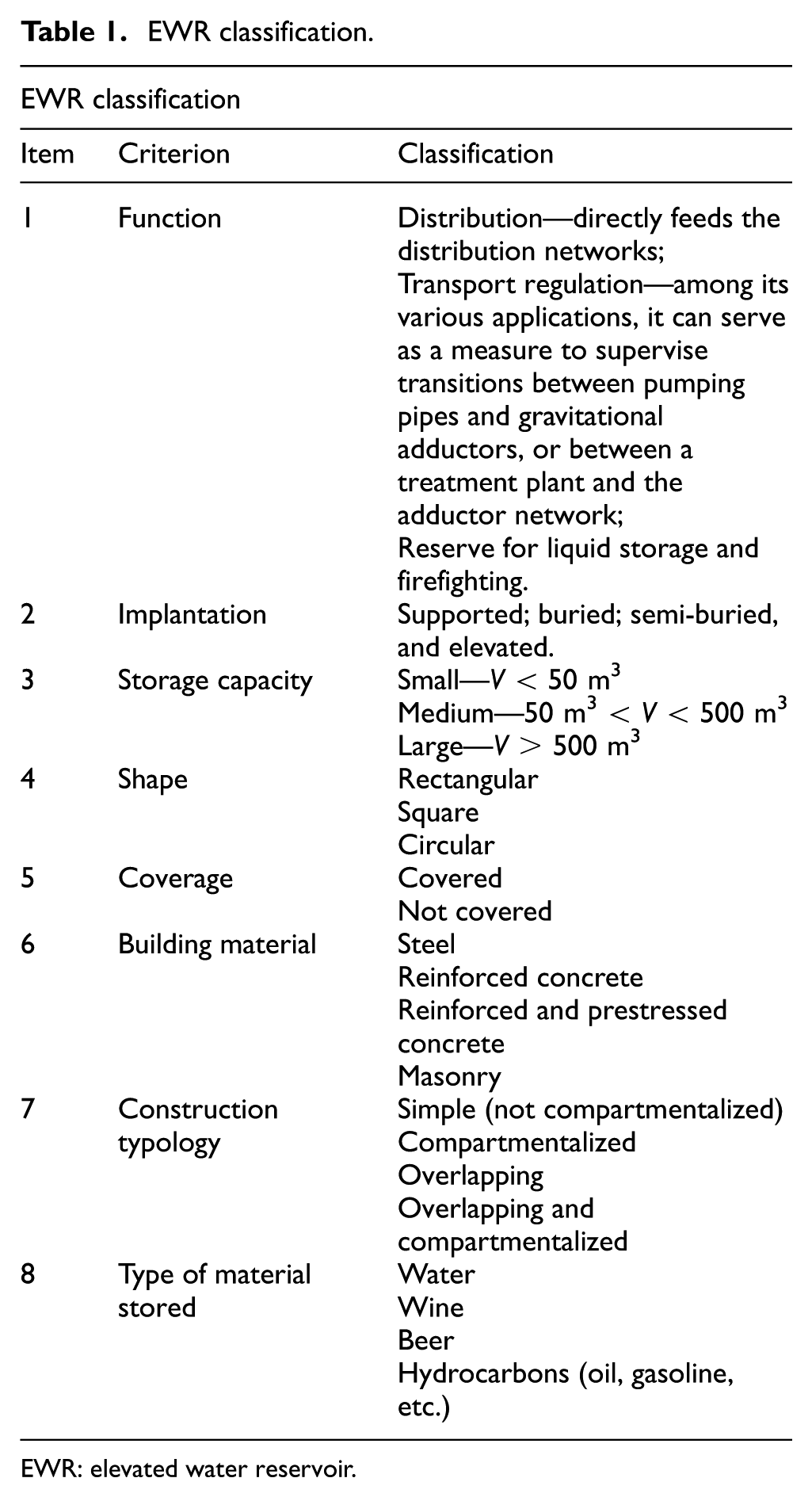
EWR: elevated water reservoir.
Costa and Arruda et al. describe the parts of elevated reservoirs2,5: (a) Vat, Tank, or Water Tower, responsible for storing the liquid; (b) Tower, available only in elevated reservoirs, which transfers the loads and the action of the wind to the foundations; (c) Foundations, which transfer the loads from the reservoir to the ground, can be direct or deep, depending on the soil conditions; and (d) Cover or Lid, which must prevent infiltration, animal entry and allow water drainage, and it can be used for the installation of antennas, as long as it does not damage the structure.
Regarding the geometry, circular reservoirs present better behavior about the distribution of efforts due to the balance between the surface and the requested loads, not only by providing greater storage capacity, but also by allowing smaller thicknesses and consequent cost reduction; reservoirs with rectangular geometry present greater demands, as they do not have symmetry between efforts and loads, which makes them contraindicated for storage of large volumes.2,3
According to Costa 5 and Toretti and Speck, 11 reinforced concrete is widely used to manufacture these structures due to versatility, strength, durability, and lower cost. However, the reinforced concrete deteriorates over time due to components’ interaction with external factors, which can generate pathological manifestations, compromising the structure’s performance. 12
Pathological manifestations in EWR
Batista 10 and Souza and Ripper 12 explain that the pathological manifestation is associated with civil construction engineering specific area that deals with the origin, the forms of manifestation, the consequences, and the mechanisms of occurrence of failures and building degradation systems.
Studies developed by Helene, Oliveira, Tinoco and Morais, Costa, Maia and Barbosa, and Batista about reinforced concrete structures, several factors contribute to the pathological manifestation emergence in these types of constructions, among them: project errors, executive anomalies, workforce, and materials, can also be analyzed by the construction phase, where design is responsible for 40% of occurrences, execution 28%, materials 18%, use 10%, and planning 4%. The main pathological manifestations detected in these constructions are: corrosion of reinforcement, fissures, cracks, infiltrations and leakage in the chamber, efflorescence, biological agents, and displacement.10,13–16
The pathological manifestations that affect EWR often have maintenance or recovery postponed due to the stop supply need, which directly affects the user’s life quality, as they are constructions that impact the population life quality. 8
Toretti and Speck 11 state that deterioration conditions neglect or ineffective repairs to solve pathological manifestations can result in costly reinforcements or demolitions. These can be avoided through quick actions to rehabilitate the building’s initial conditions or periodic preventive maintenance.
In order to detect EWR pathological manifestations, it is necessary to inspect the entire structure, an essential technical process to prevent construction accidents, which involves a systemic and sensory analysis of the use conditions, operation, maintenance, and building functionality. 17 In Brazil, this inspection is realized by industrial climbers certified by the technical standard NBR—15.475, 18 who climb down around the reservoir by using personal protective equipment, such as safety belt and hard-hat, and collective protection equipment, such as insulation tapes and anchoring tripods, to minimize the falling risk. 19
Fall from height is the leading fatal accidents cause in the construction industry, with 52.9% of incidents occurring during falling levels or maintenance services, such as structures inspection and repair, with a recurrence rate of 16.2%. 20 These accidents are increasing and currently represent 40% of accidents in the construction industry, resulting in 376 deaths.21,22
In addition to the risks to workers, inspections realized by industrial climbers involve high costs and demand excessive time. In contrast, the use of drones, or unmanned aerial vehicles (UAVs), represents a more efficient and safer alternative, allowing the high-resolution images capture and videos around EWR, which facilitates the pathological manifestation identification and enables rapid replacements in the event of accidents. 23
Analyzing the effectiveness of UAVs, Oliveira et al. show that the cost of inspecting an EWR can be reduced to one-third of the traditional method. Evaluating the time, it is possible to perform in 3 h what, before using UAV, would take between 3 and 8 days, depending on the complexity, consequently providing a reduction in workforce, greater productivity, better precision, and a reduction in the accident’s risks. However, the subsequent analysis time will depend on the professional’s expertise and the image quality collected in both methods (UAV and traditional). 23
Unmanned aerial vehicle
The International Civil Aviation Organization classified as unmanned aircraft (UA) as an aircraft that is intended to be operated without a pilot on board, while an UA piloted from a remote pilot station is a remotely piloted aircraft (RPA) or UAV. 24 The UAV is defined by the Brazilian Department of Airspace Control (DECEA) in Aeronautics Command Manual (MCA 56-5) as a device designed to operate without a pilot on board, capable of maintaining itself in the atmosphere through reactions with the air, without depending on the Earth’s surface.25, 26
UAs are classified into three categories: (a) RPA or UAV, controlled by a remote device and used for experimental, commercial, and professional purposes; (b) autonomous aircraft, with predetermined flight configurations and without human intervention during operation, whose use is prohibited in Brazilian airspace; and (c) aeromodeling, a remotely controlled UA, used exclusively for recreational purposes.23,27
UAVs are classified based on performance, weight, wingspan, payload, range, maximum altitude, speed, endurance, flight mechanism, and design. 28 In addition, UAVs are differentiated by landing and takeoff mode, aerodynamics, altitude reached, divided into classes, based on maximum takeoff weight (MTOW), from 1 to 3.29,30
Aiming to unify the various information regarding the characteristics and classifications of unmanned aerial vehicle, Figure 1 details the main concepts, definitions, and classifications of UAVs.
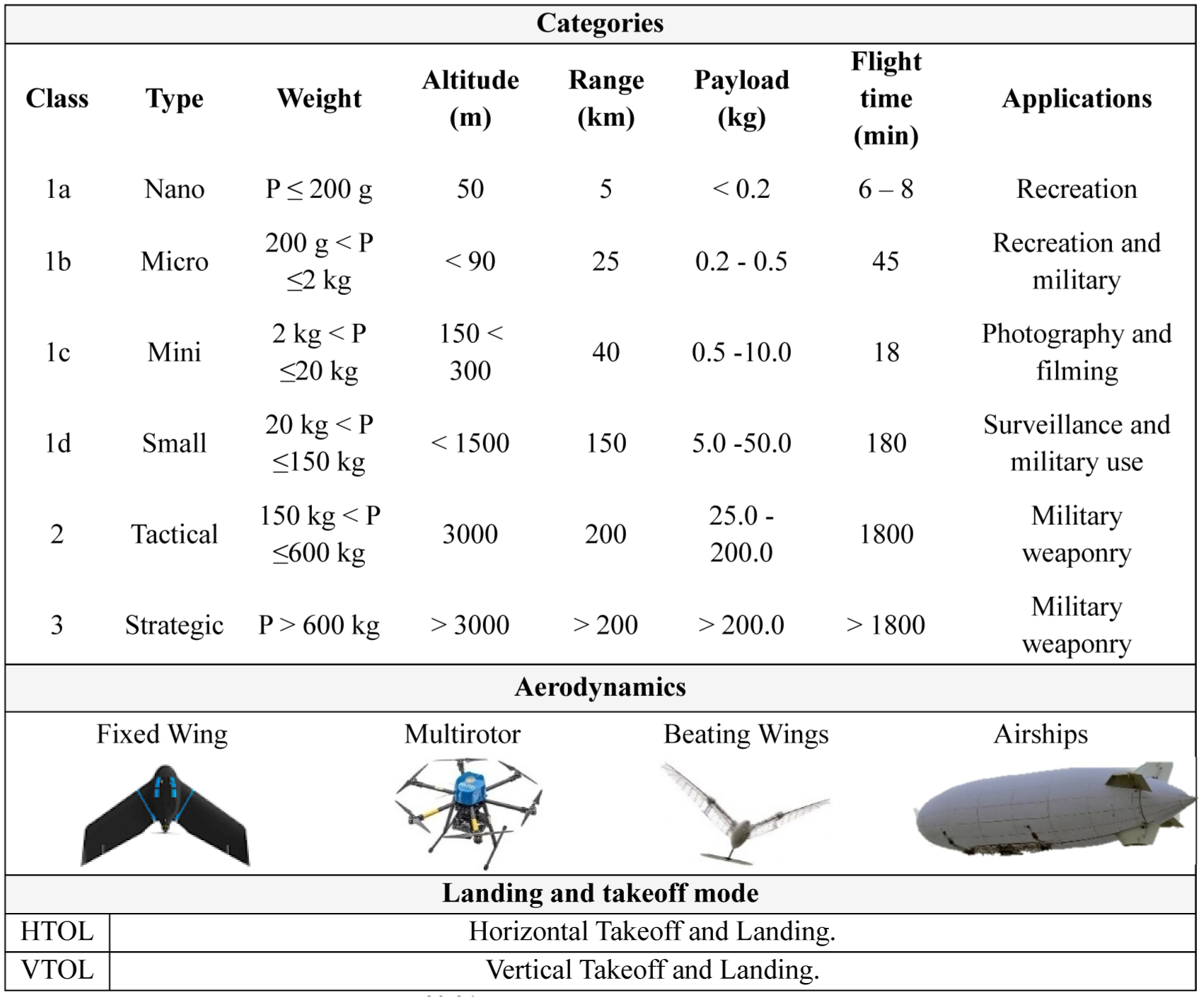
Fixed-wing UAVs take off and land horizontally, covering large areas with greater speed and altitude, but with lower wind resistance and geometric precision. 35
Multirotor UAVs have arms with motors and propellers that allow vertical takeoff and landing, greater wind resistance, precision, and flexibility in small areas. 36 They are classified by the arms number, such as quadcopters and octocopters. 30 Airships, which are light and wind-sensitive, have operational restrictions and depend on helium gas, factors that make logistics difficult. 36 Finally, flapping-wing UAVs have flexible wings inspired by birds and insects. 37
In Brazil, the regulation of UAVs is the National Civil Aviation Agency (ANAC) responsibility, which establishes the legislation on the use of UA, including the registration and enrollment of UAVs and pilots. The DECEA is responsible for monitoring the national airspace and, through the RPA System (SARPAS), supervises the flights of UA. The National Telecommunications Agency (ANATEL) regulates telecommunications equipment, including UA. 38
ANAC classifies UAVs into three categories, according to the MTOW: class 1 (above 150 kg), class 2 (from 25 to 150 kg), and class 3 (up to 25 kg, including model aircraft). Regulation RBAC-94 also defines the types of UAV operation: BVLOS (beyond visual range), VLOS (within direct visual range), and EVLOS (with assistance of observers or equipment). 39
Operations must comply with specific altitude and distance rules in areas close to Approach or Takeoff Zone, Aerodrome Surrounding Zone, Heliport Surrounding Zone, and the Flight Restriction Zone, promoting airspace safety during flights for photographic surveys of the objects studied. 27
Image processing and automated detection techniques
UAVs can be associated with various embedded or digital processing technologies in inspection activity, to increase and automate the process of identification, characterization, and classification of the detected pathological manifestations, among them are LiDAR sensor, ResNet50, You Only Look Once (YOLO), Digital Twins and digital photogrammetry, however these technologies present limitations and challenges that need to be mitigated, as noted by Groetelaars and Amorim, 40 Ayele et al., 41 Burdziakowski, 42 Hurst et al., 43 Mahmud et al., 4 and Ruiz et al. 44 and detailed in Table 2.
Technologies associated with UAV for inspection.
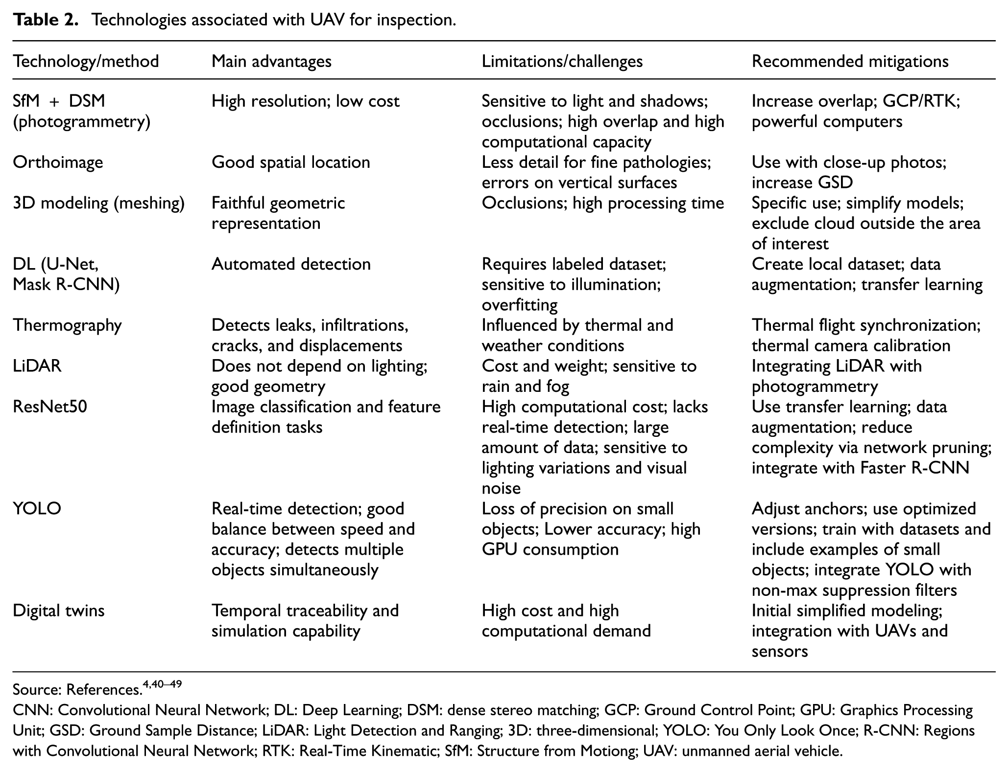
CNN: Convolutional Neural Network; DL: Deep Learning; DSM: dense stereo matching; GCP: Ground Control Point; GPU: Graphics Processing Unit; GSD: Ground Sample Distance; LiDAR: Light Detection and Ranging; 3D: three-dimensional; YOLO: You Only Look Once; R-CNN: Regions with Convolutional Neural Network; RTK: Real-Time Kinematic; SfM: Structure from Motiong; UAV: unmanned aerial vehicle.
According to the study by Rubab et al., 45 the ResNet50 model was used to monitor vehicle traffic associated with aerial photographs captured by UAVs, improving real-time traffic monitoring. Dahri et al. 46 used UAV-captured photographs to evaluate the effectiveness of solar panels combined with deep learning methods to accurately identify and classify defects. Also aiming to inspect photovoltaic solar modules, but using UAV-based thermography.
Abro et al. 47 noted the need for practical and scalable inspection solutions that can be readily implemented in the field. Aromoye et al. 48 conducted a literature review to evaluate methods for enduring extensive UAV flights, focusing on potential application in pipeline inspection, exploring the association with technologies such as artificial intelligence (AI), machine learning, and deep learning. YOLOv8 was employed by Dahri et al. 49 to improve high-altitude object detection capabilities associated with thermal images captured by UAVs, contributing to environmental monitoring, surveillance, and search and rescue operations.
Research developed by Abro et al. 50 employed cooperative quadcopter UAVs equipped with received signal strength indicators controlled by a fractiona-order PID (FO-PID) algorithm to monitor methane emissions from industrial facilities. Samaila et al. 51 analyzed video anomaly detection systems for human action recognition using public datasets. Meanwhile, Alqahtani and Abro 52 proposed an autonomous aerial surveillance system with a UAV and onboard camera for real-time border monitoring, employing YOLOv11 and machine learning for application in different environmental conditions.
For this study, specifically focused on inspecting EWR’s pathological manifestations, a UAV was used for image collection, combined with digital photogrammetry, which uses the dense stereo matching technique to correlate homologous pixels from images captured from different angles, due to its low cost and high resolution.40,53 However, as this research continues, other technologies will contribute to the advancement of knowledge.
In this context, the novelty of this study lies in the combined application of UAVs and digital photogrammetry specifically applied to EWR inspection. Although several studies explore the use of UAVs for inspections, most studies focus on building facades, bridges, overpasses, monitoring vehicle traffic, and solar panels.41,44–49,54–61 When it comes to EWRs, available studies focus on analyzing structural behaviors due to the action of external agents, such as earthquakes and wind.45,46,62–66
Therefore, this study fills the literature gap by proposing and validating, a methodological EWRs protocol inspection through the integration of UAV digital photographs, three-dimensional (3D) models, and orthomosaics constructed from digital photogrammetry, which enables the EWRs’ pathological manifestation identification.
Another innovative aspect of this study is the comparative analysis of visual resources (digital photographs, 3D models, and orthomosaics), which establishes their respective effectiveness in detecting pathological manifestations in EWRs. This experimental approach, applied to complex water supply infrastructure, represents a technological advancement and a promising alternative to conventional EWR inspection methods, such as visual inspection and the use of industrial climbers.
There is little scientific information on the UAVs’ experimental use for mapping pathological manifestations; however, the digital photogrammetry techniques have the potential to standardize the process of photographic recording and documentation, thanks to the specific requirements for coverage and capture sequence. 57 Therefore, a visual qualitative evaluation resource generated by this technology, 3D models and orthomosaics, besides the digital photographs captured by the UAV, is essential to identify which one offers the best performance in EWR detecting pathological manifestations.
This paper aims to discuss UAV technical applicability to inspect EWR pathological manifestations, through the aircraft technologies set experimental research of onboard digital camera and image processing software. The study seeks to perform a comparative analysis of the three main visual resources generated by the use of UAV and digital photogrammetry software, digital photographs, 3D models, and orthomosaics, and evaluate the visual inspection performance, differentiating itself from similar tools and works in the context of application, methodological integration, and practical and scientific support.
Accordingly, this study makes three key achievements:
Methodological validation through development of a standardized and replicable research protocol for UAV-based inspections.
Determining the effectiveness of visual resources through systematic comparative analysis.
Identification of pathological manifestations through collection, treatment, processing, and technical analysis of digital photographs.
The paper organizational outline is structured as follows: the “Methodology” section presents the procedures and technologies used to inspect EWR, validated through case studies. The “Results and discussions” section presents the main research findings addressing the use of UAVs and digital photogrammetry to detect EWR pathological manifestations. Finally, the “Conclusions” section presents the scope, objectives, and achievements, considering the contributions of research, research gap and research question, mentioning how the findings in this study may direct the stakeholders/research community, as well as highlighting future research directions.
Methodology
The methodology adopted in this paper involved the two-case studies development involving EWRs with distribution function, medium storage capacity, circular shape, covered, made of reinforced concrete, and simple construction typology, where the UAV inspection was assisted by an onboard digital camera and subsequent digital photogrammetry software.
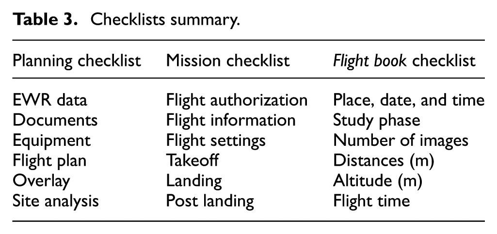
For this purpose, the activity protocol was developed, as shown in Figure 2, divided into pre-flight, execution, and post-flight stages. In the pre-flight stage, the planning checklist was used to study the site, gather information about the reservoirs and to define mission parameters. In the execution stage, the mission checklist was used to capture images flight, involving the operational procedures, such as landing, takeoff, flight type, and direction, in addition to camera settings. For the post-flight stage, the flight book checklist was used to collect data catalog, treat, and process to build the 3D models and orthomosaics, besides analyzing the visual resources generated to detect pathological manifestations and their respective efficacies. The checklist’s summary is demonstrated in Table 3.
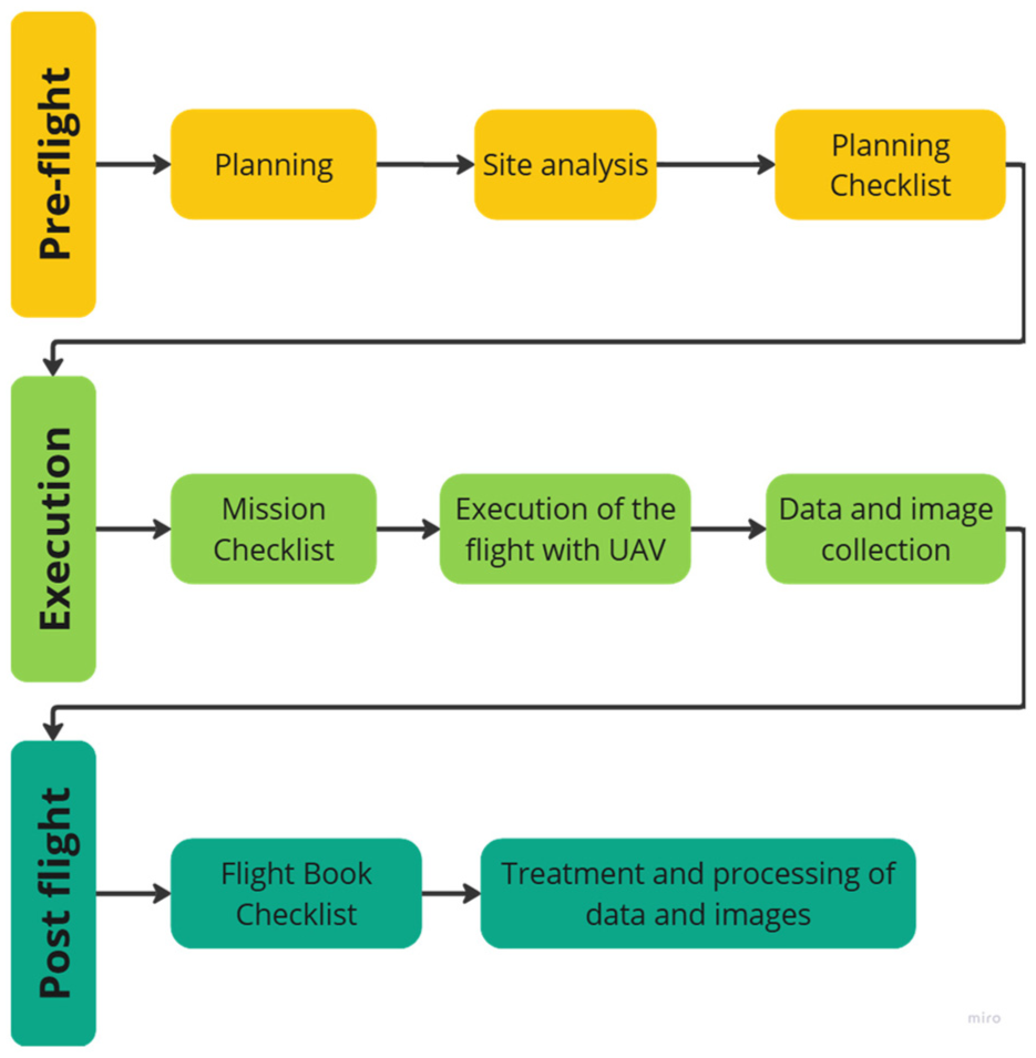
Inspection flowchart with UAV in EWR. UAV: unmanned aerial vehicle; EWR: elevated water reservoir.
Checklists summary.
Pre-flight: planning
The EWR selection was defined according to authorization from the Pernambuco Sanitation Company (COMPESA) and availability, disposition, access, and safety of those involved in the activity. Therefore, it was necessary to be part of Conecta, a mentoring COMPESA program, which enabled access information from the case studies.
Thus, case studies were realized on EWR in the Metropolitan Area of Recife, Pernambuco State, Brazil Northeast. Initially, the EWR Miramar was chosen, which was built in 1990, and it is located at Alto do Céu community in Recife city (Figure 3(a)). Its supply is provided by the Water Treatment Station Alto do Céu, through the Treated Water Pumping Station Miramar, under the COMPESA Metropolitan Business Management East (GNM East) responsibility. This EWR is 13 m high, it has a storage capacity of 50 m3, tower structured, which receives a contribution of approximately 25 l/s, and supplies the upper part of the Cajueiro district and a section of the upper part of the Fundão district. It is estimated that a population of 3311 inhabitants or approximately 946 households are supplied by this reservoir. 67
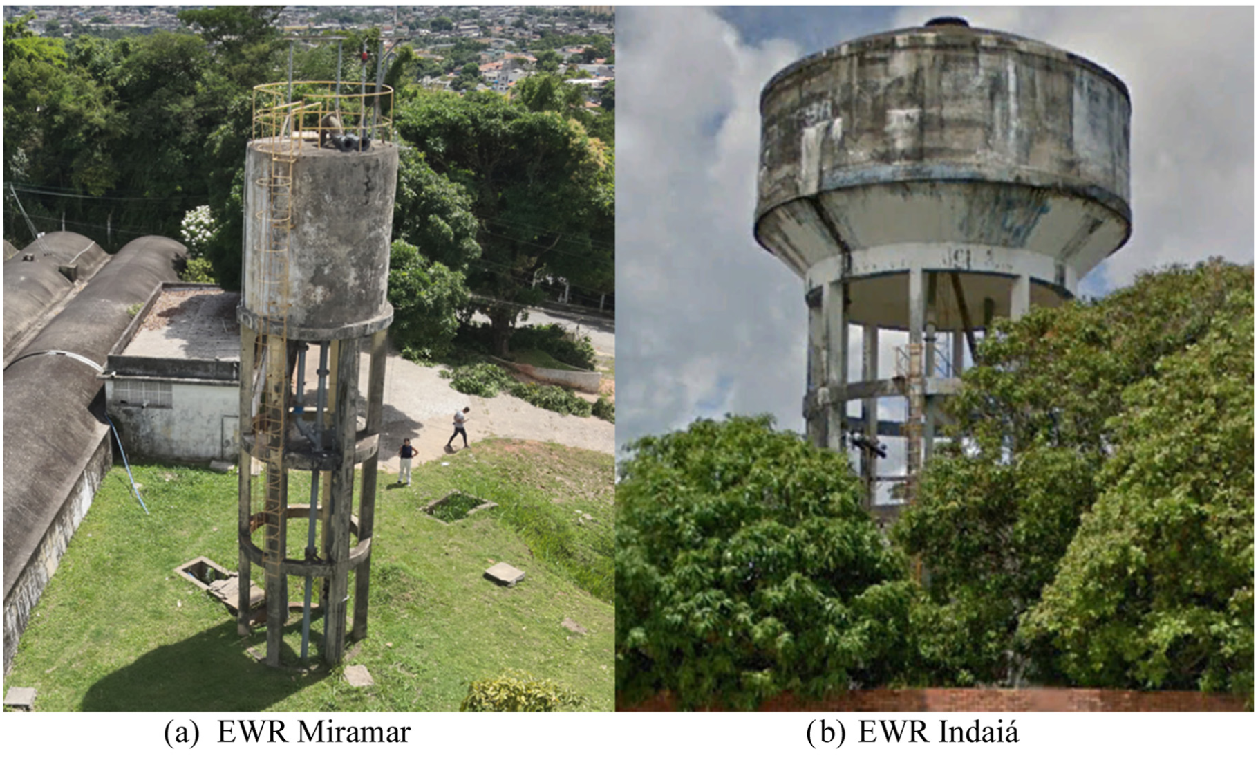
Case studies. (a) EWR Miramar; (b) EWR Indaiá. EWR: elevated water reservoir.
The second reservoir chosen was the EWR Indaiá located in Nossa Senhora do Ó district, Paulista city, Recife city Metropolitan Area, Pernambuco State (Figure 3(b)). This EWR is under the COMPESA Metropolitan Business Management North (GNM North) responsibility, and it is supplied by the artesian well P.7.1 built in the same location. This reservoir was designed for water distribution, and it has a storage capacity of 300 m3, a height of 22 m, tower structured, which supplies the Nossa Senhora da Conceição district. It supplies approximately 2462 households or 8617 people, approximately. 67
The research UAV was the Mavic 3 Thermal (Figure 4), produced by DJI. According to Brazilian legislation, it is a Quadcopter-type UAV (four rotors), and it is classified as class 3. 39
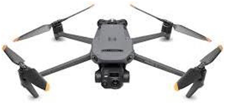
Unmanned aerial vehicle. 68
This UA weighs 920 g with propellers, considered portable, and has unfolded dimensions of 347.5 × 283 × 107.7 mm (length × width × height). The device is equipped with two batteries with 45 min autonomy, controlled via DJI RC Pro Enterprise remote control with integrated high-definition display. It also has a gimbal with three-axis stabilization (tilt, rotation, and pan). It allows tilt between −90 and 45°, in addition to three cameras—Wide Angle, with 1/2-inch CMOS sensor, effective pixels 48 MP and zoom up to 56 times—Telecamera, 1/2-inch CMOS, effective pixels: 12 MP—and the Thermal Camera, with a maximum image size of 640 × 512 pixels, which allows captures in JPEG and MP4 formats. 68
The UAV image capture used the software’s Transmission Tower configuration Pix4D Capture Pro. In areas with obstacles orbital flight was adopted, with two sequential flights and a minimum overlap of 15% between the different altitudes, 69 by ensuring fidelity in 3D construction. A single vertical flight was used for reservoirs without obstacles, covering from the ground to the highest point in a single flight, by ensuring continuity in the images.
The Agisoft Metashape software was selected for image processing due to its low cost, easy-to-use platform, and faithful reconstruction of the studied objects, which could perform orthorectification and processing of visual data to generate 3D models of the studied objects and their respective orthomosaics. The Agisoft software version was Metashape Professional 2.1.1 for 64-bit operating systems.
After equipment, tools, and technologies definition, the flight plan was realized observing camera positioning configurations, image overlap, image capture sequence, UAV action when capturing (hovering) and maximum, minimum, and average altitude reservoir points. In addition, the site’s surroundings were studied to avoid possible obstacles.
The UAV quality inspection depends on imaging technology and efficient control in data collection. Setting the camera according to the object shape, capturing at least three images per point and ensuring adequate overlap, ensure accurate digital reconstruction, minimizing errors in point identification. 70
Unlike capturing images of objects with flat surfaces, such as building facades, the circular geometry of EWR does not require the horizontal or vertical direction configuration. In the cases studied, the inspection path is circular or elliptical, depending on the configuration, and only requires defining the flight direction (left or right). This avoids stopping to change direction by ensuring continuity, stability, and reduced flight time.
Pitombeira and Reis Filho state that image overlap, which is essential for the digital model quality, should be between 70 and 90% to ensure submetric accuracy. Lower percentages do not accurately portray the object, while values above 90% increase processing time without significantly contributing to the detailing of the 3D model. Despite requiring greater computational capacity, high overlap improves model quality. Thus, overlaps of 75 and 80% were used to capture object images by maintaining a horizontal distance of 8 m and a vertical distance of 5 m for the reservoirs. 71
Execution: image capture
The image collection was realized according to the previous planning defined for both case studies by operating the aircraft in a mixed, manual, and automated manner, assisted by at least one observer. The observer was responsible for informing the pilot about the proximity to obstacles, aircraft, birds, non-consenting people, and possible occurrences in the surroundings that could compromise the flight safety and the personnel involved.
At EWR Indaiá, two flights were realized at different altitudes and along the same trajectory, due to the bulging condition of the water tower lower slab, with the battery replacement and a total mission of 60 min time. For EWR Miramar, the mission required only a single flight to capture the images necessary for 3D reconstruction without battery replacing, with a total flight time of 28 min. The information recorded during the image collection highlights: the number of visual assets collected (photos and videos), the distance traveled, the maximum altitude, and the flight duration, all recorded in the flight checklist (checklist flight book).
The images were stored in JPG format, cataloged, and organized in a file specific to each reservoir, enabling subsequent processing of the collected data using digital photogrammetry software.
Post-flight: image processing
For data processing and generation of 3D models, a DELL computer with an Intel Core i7-8565U processor, 16 GB of RAM, 8 GB Intel UHD Graphics 620 shared GPU, 2 GB AMD Radeon 520 dedicated GPU, and Windows 11 operating system was used. Given the amount of available RAM, it is possible to process between 300 and 500 10-megapixel photos, which, added to the object reconstruction parameters established in the software, will define the requirement for computational resources and processing time. 72
It is important to highlight the use of all reconstruction parameter configurations at the maximum capacity and quality allowed by the software to increase superior quality and faithful reconstruction of the objects. The Agisoft Metashape software tools were used: align photos, build dense cloud, build mesh, build texture, and build orthomosaic, following the workflow shown in Figure 5.
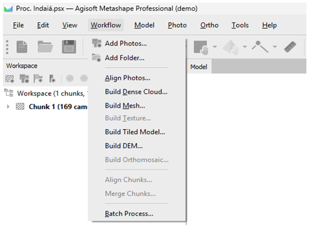
Agisoft Metashape workflow.
According to Figure 5, the following procedures were carried out to process the images and build the 3D models and orotmosaics:
Align photos: Aligns images with high-precision settings using Tie Points, generating low-density cloud points, allowing only visualization of the EWR geometry.
Build dense cloud: Constructed from Tie Points, with maximum quality parameters and Mild filtering, aiming to increase density and reduce voids, resulting in better geometric representation.
Build mesh: Constructs the 3D model with better digital reconstruction quality and better geometric visualization, using the following settings: surface type, arbitrary 3D model; data source, dense cloud; high face count; and interpolation, enabled.
Build texture: Applied to the 3D model to improve visual quality. Settings: generic mapping, maximum intensity, hole filling enabled, and ghosting filter enabled.
Build orthomosaic: Based on the 3D model, orthomosaics of the EWRs were generated using the following parameters: Type, Planar; Coordinate system, SIRGAS 2000; surface, mesh; combination mode, mosaic (default); void filling, enabled.
Therefore, the visual resources of each EWR were constructed, allowing the orthomosaics generation. For better visualization and understanding of the process of constructing visual resources through photogrammetry software, Figure 6 shows the resources generated in the Tie Points, 3D model, and orthomosaic stages, allowing the analysis of the quality of the different products.
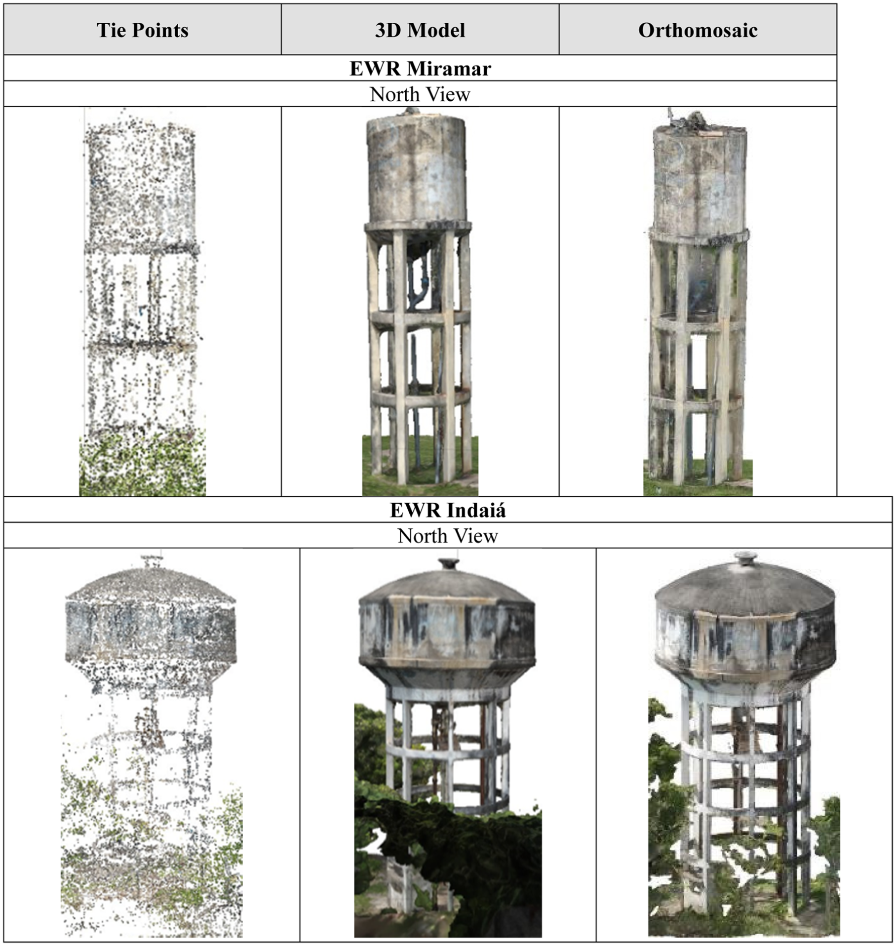
Visual resource models built in Agisoft Metashape.
For this purpose, the reservoir was divided into five parts, based on the cardinal position (north, south, east, and west), in addition to the lid. It is worth noting that, for the 3D model construction, Miramar and Indaiá EWRs dense cloud totaled approximately 6 million and 18 million points, respectively, in addition to approximately 858 thousand and 3 million faces.
It should be noted that in the Tie Points stage, the resource does not provide the visual quality needed to further detect pathological manifestations, allowing only the geometric identification of the object. The 3D model provides visual enhancement, allowing the identification of real EWR patterns and their respective textures, obstacles, and constituent materials. The orthomosaic provides clear visibility of the actual EWR situation in the analyzed section, allowing for more comprehensive identification of incident problems.
Due to the complexity and maximum quality settings, digital object reconstruction required more computational resource time. Processing the data from EWR Miramar took 12 h and 35 min, while processing time for EWR Indaiá was 10 h and 38 min.
To define the total time for producing visual resources, everything from the image capture activity to the orthomosaic export procedure was taken into consideration. After the assets and visual resources were produced, the phase of detection, identification, confirmation, location, and classification of the pathological manifestations that affect EWR began through visual inspection of each photograph, 3D model, and orthomosaic produced. The analysis method was standardized, starting from top to bottom and from left to right on each face oriented by the cardinal position of the reservoir and the lid.
Results and discussions
Through the application of the pre-flight, execution, and post-flight stages and the visual resources production, it was possible to analyze, identify, locate, characterize, and quantify the EWR pathological manifestations using digital photogrammetry software and UAV collected data. This allowed the analysis of which resources and software provide greater effectiveness and clarity to pathological manifestation identification.
Therefore, the 3D model returned a faithful and precise studied objects digital reconstruction, contributing to the EWR geometric and spatial representation. However, the visual resource demonstrated lower effectiveness in identifying pathological manifestations.
The orthomosaics constructed from the 3D models allowed better spatial localization, when compared to the 3D object and orthogonal view representation in each reservoir’s cardinal position. They allowed a greater quantity of identification of pathological manifestations than the 3D model, but in a smaller quantity than the UAV digital photographs collected.
Thereby, the visual resource was the most effective, enabled better visualization and identification of the greatest number of pathological manifestations were UAV digital photographs captured. These photographs provided greater precision in the EWR of pathological manifestations identification and also enabled the construction of damage maps (Figure 7). The visual resource comparative analysis not only demonstrates the technical benefits of each product but also identifies the best visual resources for EWR inspection purposes.
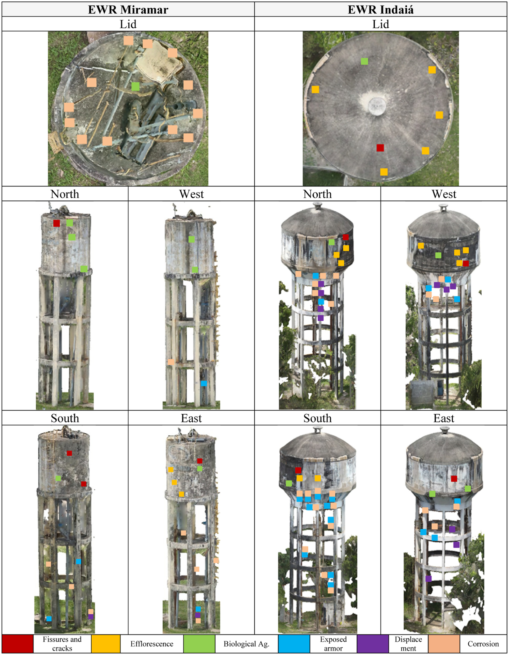
EWR damage maps. EWR: elevated water reservoir.
The effectiveness of each visual resource was analyzed to identify pathological manifestations according to the construction time, which revealed important differences, as demonstrated in Figure 8.
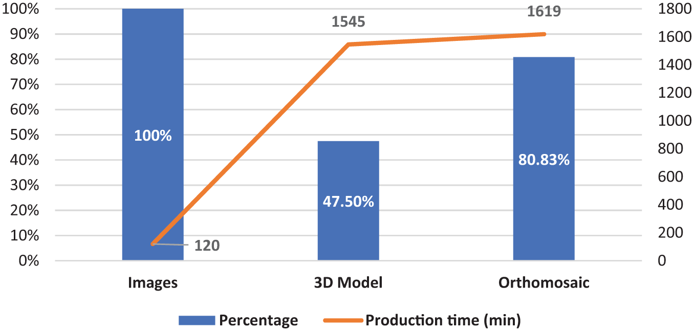
Comparative analysis of the effectiveness of visual resources as a function of time.
It is worth noting that pathological manifestation identification was carried out through individual analysis of the digital photographs in each EWRs section. Subsequently, the images were checked and confirmed using the other visual resources, including the orthomosaics, analyzed using digital photogrammetry software, which helped in the spatial localization and detected damage classification, contributing to the damage maps construction.
The systematic integration of UAVs with digital photogrammetry applied to the EWRs inspection highlights the novelty of this study. As observed in this research, while UAV-based inspections have been increasingly reported in the literature, the majority of research has concentrated on applications involving building facades, bridges, pavements, overpasses, monitoring vehicle traffic, and solar panels.45,46,57,59,61
According to Figure 8, digital photography has a shorter generation time than other visual resources because it does not require additional processing and processing. As observed in this study, UAVs significantly reduce inspection time (from 3 days to 3 h) and associated costs by up to a third, compared to traditional methods, which expose workers to risks. Furthermore, UAV inspections also enable integration with digital twins and automated detection systems based on AI, providing georeferenced, high-resolution visual assets, favoring predictive and preventive maintenance techniques, representing a significant methodological and technological advance.
Analyzing the pathological manifestations detection percentage, photographs allowed the identification of a larger quantity and, therefore, assuming the value as total, approximate reductions were identified for the pathological manifestation identification by the 3D model and orthomosaic visual resources were 50 and 20%, respectively, in comparison to the manifestations that were not identified by these visual assets, in addition to a production time approximately seven times greater.
In general, the 3D models’ contribution proved dispensable for identifying pathological manifestations, given the high suppression of detected pathological manifestations compared to digital photographs collected with UAVs, also measured the excessive time and high computational requirements. The same cannot be recommended for orthomosaics, due to the possibility of integration with digital photographs, which also serve as verification for most of the pathological manifestations detected, as observed by Groetelaars and Amorim, 40 Serrat et al., 73 Walter et al., 74 Ballesteros and Lordsleem Júnior, 57 Oliveira and Lima, 53 and Silva et al. 70
The EWRs’ pathological manifestations identified are detailed in Table 4, individually by EWR and by each visual resource.
Pathological manifestations detected in EWR.
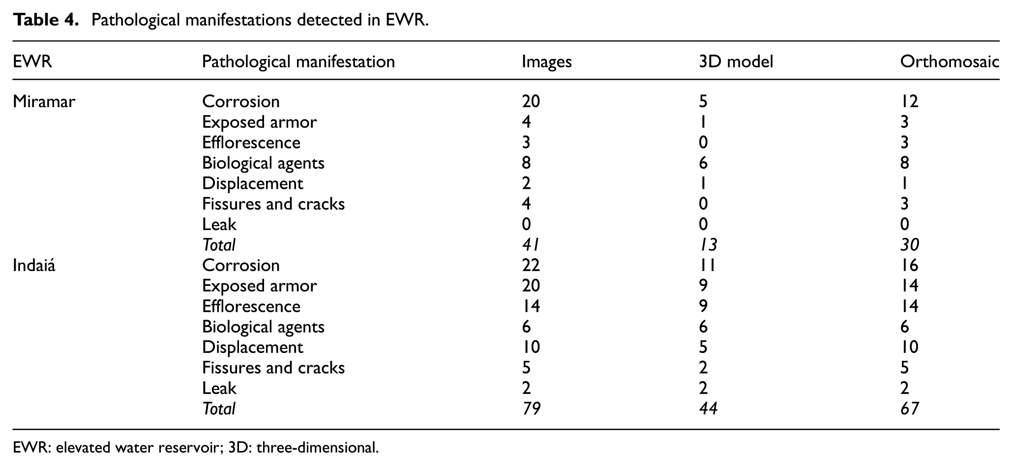
EWR: elevated water reservoir; 3D: three-dimensional.
The pathological manifestation with the highest incidence identified in EWR was corrosion, corresponding to 35% of the total pathological manifestations detected, followed by the exposure of reinforcement, with 20%, and efflorescence, with 14.17%. Thus, digital photographs enabled 100% identification, followed by orthomosaics, with 80.83% of the findings and, finally, 3D models, which enabled the identification of 47.50% of the pathological manifestations affecting the studied reservoirs.
Adapting, for this study, the energy efficiency tables approved in the Brazilian Labeling Program of the National Institute of Metrology, Quality, and Technology, 75 in order to establish qualitative criteria for visual resources based on the capacity to detect pathological manifestations that each visual asset enables, the three resources were classified alphabetically, from A to C, where A corresponds to the greatest possibility of detection and C the lowest, for each pathological manifestation.
Thereby, classification A was established for the resources that allowed total percentages (100%) of pathological manifestations detected. For percentages lower than 100% and equal to or greater than 70%, classification B was assigned, and for detection percentages lower than 70%, classification C was assigned, as shown in Table 5.
Visual resources classification.
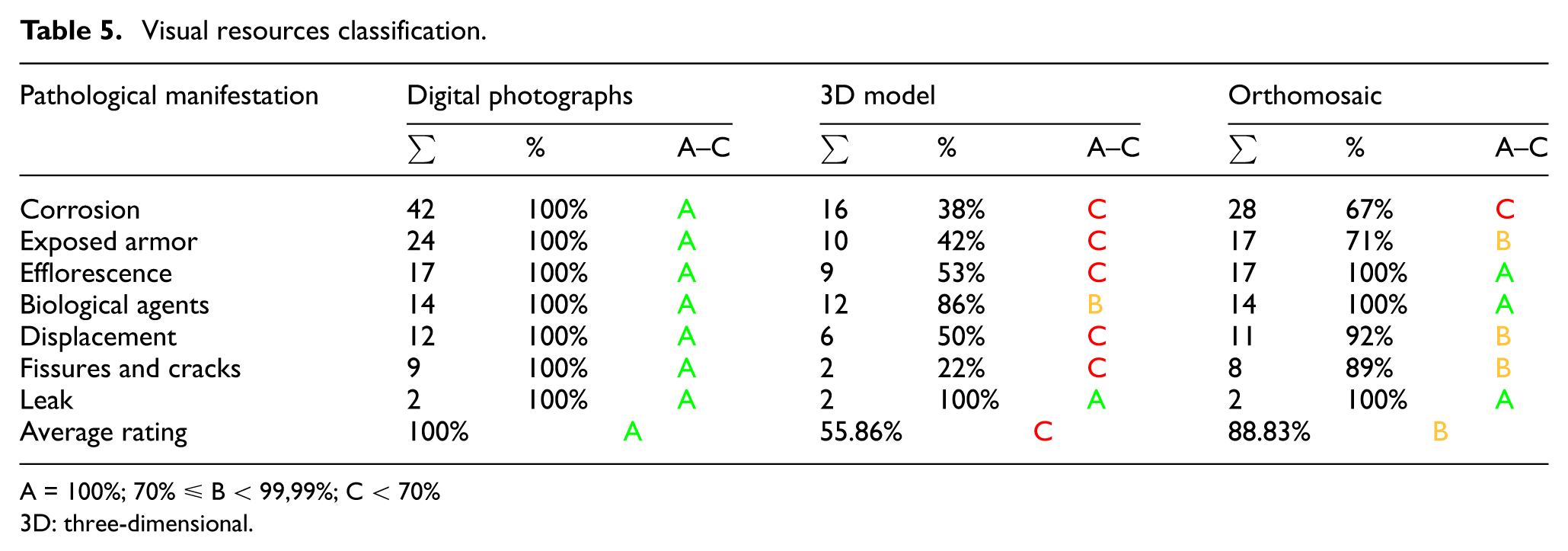
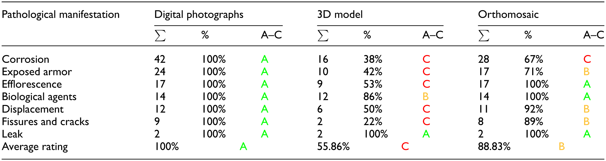
A = 100%; 70% ≤ B < 99,99%; C < 70%
3D: three-dimensional.
Thereby, it can be seen that the 3D model enabled a maximum condition, classification A, for detecting pathological manifestations only in the case of leakage, while the orthomosaic allowed maximum detection, classification A, to identify efflorescence, biological agents, and leakage. Therefore, the visual resources obtained an average classification: A for digital photographs, C for 3D models, and B for orthomosaics, this is confirmed by the time allocated for constructing of the visual resources, since digital images require considerably less time to obtain.
Thus, as observed in the studies by Serrat et al., 73 Walter et al., 74 and Ballesteros and Lordsleem Júnior, 57 it is possible to classify digital photographs as the most effective visual resource for inspecting EWR, given that they require less production time and allow for a greater quantity of pathological manifestations detected, by contributing to the quality and accuracy of the inspection activity in EWR. The other resources present high demands on computational resources, long production time, and limitations for the detection of pathological manifestations.
However, the usefulness of the orthomosaic to identify the position of pathological manifestations in EWR is highlighted, especially when it is not possible to obtain a comprehensive image of the analyzed point through digital photographs. Although it is the digital resource that demands the most time to build, it also assists the production of damage maps and maintenance activities.
3D models were less effective than others for inspecting EWR pathological manifestations, as they allowed lower quality for detecting pathological manifestations and required excessive time for their production. However, this resource returns a faithful geometric representation of the objects studied, which proves to be interesting for future renovation or even reconstruction activities.
Analyzing the studies available in the scientific literature, they are still limited and predominantly focused on the analysis of structural behaviors under external actions, such as earthquakes, seismic activity, wind-induced oscillations, and dynamic loads, rather than the direct detection and characterization of pathological manifestations.65,66 This represents a significant gap in scientific research knowledge, since EWRs are critical infrastructure for urban water supply, where pathologies can compromise both functionality and public safety.
To address this shortcoming, the present study proposes and validates, through two case studies, a standardized methodological protocol for EWR inspection. This protocol integrates three visual resources generated from UAV-based image acquisition and digital photogrammetry processing: digital photographs, 3D models, and orthomosaics. These resources were systematically compared in terms of precision, resolution, and effectiveness in detecting pathological manifestations, enabling a critical assessment of their strengths and limitations.
Thus, the study’s results reveal the effectiveness of UAV use associated with digital camera to inspect EWR and identify corrosion, exposed reinforcement, efflorescence, biological agents, displacement, fissures, cracks, and leaks in the water tower.
Through the use of digital photogrammetry techniques, corroborated by Groetelaars and Amorim 40 and Oliveira and Lima, 53 to capture the images, combined with the application of checklists, the procedure for collection, treatment, processing, and detection of pathological manifestations was structured, by observing the standardization, capture sequence, and overlap between the images, which avoid the occurrence of occlusion points, and ensure quality to the study.
Therefore, this study differs from similar works and tools in three main aspects:
Application context—By targeting water supply infrastructure, promoting social impact, which is still little explored in the scientific literature.
Methodological integration—By articulating standardized protocols (planning, execution, and post-execution), digital processing (photogrammetry using Agisoft Metashape software), and construction of damage maps, providing replicable guidelines.
Practical and scientific support—By validating digital photographs as the most effective visual resource for identifying pathological manifestations in EWRs while demonstrating that 3D models and orthomosaics are useful for geometric representation and spatial location, respectively, providing comparative evidence that can help managers, companies, and researchers to define the appropriate resource to be employed, according to the need and purpose of the inspection, going beyond a simple technological application.
Thus, the methodological protocol proposed in this study can serve as a practical tool for managers, ensuring greater operational safety, enhancing preventive maintenance planning, and reducing its frequency, thereby avoiding costly structural interventions. For companies, the method established in this study offers objective criteria for selecting the most appropriate EWRs inspection technique for each specific need, promoting better efficiency and cost.
The scientific community may benefit from the validated empirical foundation as a reliable reference for future research on technological integration aimed at detecting EWRs’ pathological manifestations. Moreover, this work provides a valuable starting point for the development of a broader comparative database, strengthening the knowledge base and fostering advances in structural monitoring and sustainable water infrastructure management.
Conclusions
This study aimed to assess the technical feasibility of using a UAV combined with digital photogrammetry to inspect EWRs, an important water supply infrastructure for the population, for detection, identification, and characterization of pathological manifestations. It focused on analyzing the effectiveness of three visual resources: digital photographs, 3D models, and orthomosaics, collected and constructed through two case studies under real operating conditions.
Thus, the objective was to experimentally validate the methodological procedure, which employed the UAV, an onboard digital camera, and image processing software, enabling the EWRs’ pathological manifestation detection and to evaluate the performance of the visual resources for this activity.
The need to promote greater safety for those involved in EWR inspection activities, combined with cost and time savings, underscores the significance of this study. It offers an innovative and safe alternative, directly contributing to the sustainable management of EWRs. Conventional methods expose workers (industrial climbers) to critical risk, require excessive time, and, consequently, increase inspection costs.
Therefore, the application and validation of UAV technology, specifically in the context of EWR inspections, through a comparative analysis of visual resources under real operating conditions, represent a methodological advancement that has not yet been explored. It promotes originality, differentiates itself from current scientific literature, and answers the research question by identifying the most effective visual resource and the feasibility of using UAVs combined with digital photogrammetry to inspect EWRs.
Thus, the main contribution of this research lies in the development and provision of a replicable and technically validated protocol, suitable for adoption by managers, companies, and scientific community. This protocol expands real-time monitoring capabilities, promotes preventive maintenance of EWRs, reduces the frequency of interventions, furthering knowledge about structural monitoring, and opens the possibilities for integration with automated detection technologies for pathological manifestations.
The research sought to fill the gap in scientific studies focused on the EWRs’ pathological manifestation inspection, specifically on the application of UAVs to collect images and the use of digital photogrammetry to construct visual resources, providing robust experimental evidence regarding the capabilities and limitations of this technique.
Regarding operational aspects, the UAV presented a simple interface, good hardware and software integration, and efficient sensors. However, it proved vulnerable to adverse weather conditions, such as strong winds, rain, and light variations, which compromise flight stabilization and image quality. Furthermore, digital photogrammetry requires appropriate image overlay for the construction of visual resources, aiming to avoid flaws and occlusions. This can be hampered by the geometric complexity of the studied object, surrounding obstacles, and bird strikes. It also depends on the computational capacity to process the images in a timely manner. Another important factor is the pilot’s handling skills and experience, as they must maintain a steady and continuous trajectory to ensure the accuracy of the collected data.
To mitigate these limitations, resulting from operational and experimental aspects, the following are recommended:
Acquisition of UAV that can withstand wind gusts while remaining stable and that is waterproof for rain events.
Expand the technologies used to detect pathological manifestations, prioritizing those less susceptible to light variations, such as thermal cameras and LiDAR sensors.
Automate flights, employing systems such as RAPTOR 76 , establishing a high percentage of image overlay (75–80%), eliminating flaws and occlusions.
Maintain the minimum distance of 3 m between obstacles surrounding EWRs, when present, avoiding the activity if it is impossible to guarantee the safety of the equipment and personnel involved in the inspection.
Invest in propeller guards and parachute for UAV to prevent damage and aircraft crashes in cases of bird strikes, and utilize at least one observer throughout the flight.
Ensure adequate computing capacity of the equipment used for image processing is minimally consistent with the technical specifications assigned to the digital photogrammetry software, avoiding long periods of machine demand. Analyzing the experience gained from this study, although the computer settings used for digital processing using photogrammetry software are higher than the minimum required, the time and computational requirements were considered high; therefore, a higher configuration than that used in this study is recommended, in addition to excluding the point cloud outside the area of interest.
Thorough and continuous pilot training and development, as well as frequent updates to keep up with advances in UAV technology.
Define a specific protocol for adverse weather conditions, establishing landing, takeoff, and eventual flight postponement criteria.
Integrate UAV with embedded technologies, such as thermography and laser-induced breakdown spectroscopy to carry out complementary tests and trials in replacement of the percussion test and carbonation depth analysis.
Therefore, this study highlights that UAVs constitute a promising innovation for EWRs inspection, but the consolidation as an engineering tool requires overcoming the limitations presented in this work. By addressing these gaps, this research enriches scientific knowledge and proposes practical strategies to improve the technology application in EWRs.
Thus, the main achievements of this study are:
Methodological validation—Development of a standardized and replicable research protocol for UAV-based inspections, covering planning, execution, and post-execution procedures.
Collection and construction of visual resources—Production and comparison of three digital assets (digital photographs, 3D models, and orthomosaics) using UAVs and digital photogrammetry, demonstrating their strengths and limitations in EWR inspections.
Identification of pathological manifestations—Collection, treatment, processing, and technical analysis of 318 images that enabled the identification of 120 pathological manifestations in the case studies, the most frequent of which were corrosion (42 occurrences), exposed reinforcement (24 occurrences), and efflorescence (14 occurrences), respectively.
Determining the effectiveness of visual resources—Through systematic comparative analysis, determining the performance and effectiveness of the collected and constructed visual resources, establishing digital photographs as the most accurate and cost-effective resource, orthomosaics as the most effective for spatial location and mapping of occurrences, and 3D models as the most effective for geometric representation and future renovations or reconstructions.
Time and cost assessment—It was clarified that using a UAV to inspect EWRs significantly reduces the execution time, from days to hours, and the cost, approximately one-third of the cost of an industrial climber.
Legal and regulatory feasibility—Field validation of the technique, observing regulatory and legislative frameworks (ANAC and DECEA) in the Brazilian context, and allowing for international replication, with minor adaptations to the international standards in force at the inspection site.
Scientific and practical contribution—The research filled a gap in the literature by using aerial inspection techniques in EWRs under real conditions, offering experimental evidence and practical guidelines for stakeholders and research community.
Future research will focus on developing advanced deep learning techniques for automated, accurate, and efficient identification of EWR pathological manifestations. These models will be trained on large-scale datasets covering a wide range of environmental and structural information, improving their practical implementation by building a database of EWR pathological manifestations.
Furthermore, integration techniques between UAVs, embedded technologies (infrared thermography), and AI (CNNs and YOLO) will be developed to mitigate the need for additional trials and tests, such as percussion and carbonation depth testing. Concurrently, technical guidelines for inspecting EWRs using thermal images captured by UAVs will be explored and developed, integrating fundamental principles of predictive maintenance with preventive maintenance. This integration is expected to enhance efficiency, scalability, and extrapolation capability of the method, ensuring performance in future inspections to determine the structural health of EWRs.
Footnotes
Acknowledgements
The authors would like to thank the Pernambuco Science and Technology Support Foundation (FACEPE) for financial support and the Pernambuco Sanitation Company (COMPESA) for the information, authorizations, and support.
Declaration of conflicting interests
The authors declared no potential conflicts of interest with respect to the research, authorship, and/or publication of this article.
Funding
The authors received no financial support for the research, authorship, and/or publication of this article.