
Abstract
The high attrition rate of drug candidates late in the development process has led to an increasing demand for test assays that predict clinical outcome better than conventional 2D cell culture systems and animal models. Government agencies, the military, and the pharmaceutical industry have started initiatives for the development of novel in-vitro systems that recapitulate functional units of human tissues and organs. There is growing evidence that 3D cell arrangement, co-culture of different cell types, and physico-chemical cues lead to improved predictive power. A key element of all tissue microenvironments is the vasculature. Beyond transporting blood the microvasculature assumes important organ-specific functions. It is also involved in pathologic conditions, such as inflammation, tumor growth, metastasis, and degenerative diseases. To provide a tool for modeling this important feature of human tissue microenvironments, we developed a microfluidic chip for creating tissue-engineered microenvironment systems (TEMS) composed of tubular cell structures. Our chip design encompasses a small chamber that is filled with an extracellular matrix (ECM) surrounding one or more tubular channels. Endothelial cells (ECs) seeded into the channels adhere to the ECM walls and grow into perfusable tubular tissue structures that are fluidically connected to upstream and downstream fluid channels in the chip. Using these chips we created models of angiogenesis, the blood–brain barrier (BBB), and tumor-cell extravasation. Our angiogenesis model recapitulates true angiogenesis, in which sprouting occurs from a “parent” vessel in response to a gradient of growth factors. Our BBB model is composed of a microvessel generated from brain-specific ECs within an ECM populated with astrocytes and pericytes. Our tumor-cell extravasation model can be utilized to visualize and measure tumor-cell migration through vessel walls into the surrounding matrix. The described technology can be used to create TEMS that recapitulate structural, functional, and physico-chemical elements of vascularized human tissue microenvironments in vitro.
Keywords
Introduction
The pharmaceutical industry faces a significant challenge in reducing drug failure late in the drug development process. A recent review of clinical trials identified a total of 148 failures in 2011 and 2012 between phase II and submission. Of the 105 that reported reasons for failure, 56% were due to lack of efficacy and 28% were due to safety issues. 1 These data have led the pharmaceutical and biomedical industries to demand alternative in-vitro tools that have the capacity to better predict clinical outcomes. Such tools will allow investigators to identify failed drugs early in the development process and divert funding toward candidates with a higher potential for clinical success. Currently, the standard models used early in the drug development process are 2D in vitro and animal models. Research has shown that cells grown in three dimensions have significantly different features and are more representative of the in-vivo environment than those grown in monolayers on plastic dishes.2–4 Although animal models serve as a valuable tool to screen drugs for efficacy and toxicity in a complete physiological system, they are expensive, fraught with ethical concerns, and do not always accurately predict clinical outcomes. Together, these observations have increased the demand for 3D in-vitro models that more closely resemble, and thus predict in-vivo functionality. This need is further evidenced by the federal government's investment in the development of such systems. In September of 2011 the National Institutes of Health (NIH) and Defense Advanced Research Project Agency (DARPA) each launched a five-year program to support the development of in-vitro platforms that model microenvironments of human tissues to be used for toxicology screening and research applications.
In response to these demands, a number of research groups are developing 3D in-vitro models that are more physiologically relevant, reproducing the appropriate cell–cell and cell–extracellular matrix (ECM) interactions. Although a relatively new area of research, the field is growing quickly and many different terms have been used to describe the resulting systems, including: organ-on-chip, body-on-chip, and microphysiological systems. To address these inconsistencies we propose using a term more descriptive of what these technologies enable; that is, tissue-engineered microenvironment systems, or TEMS. Such systems facilitate 3D growth of multiple cell types within a supporting biological matrix. An additional level of in-vivo functionality is achieved by combining these 3D tissue cultures with fluidic networks. These perfusion systems provide fluid flow and can be utilized to create and sustain gradients and to provide nutrients and test compounds throughout the 3D culture. Early experiments suggest such TEMS have significant potential for improving drug development and biological research. Utilizing this approach, a number of groups have generated new models of specific tissues and diseases, many of which are described in detail in this journal issue or reviewed elsewhere.5–7 In short, cells are grown in a channel or on a membrane coated with ECM, which is then perfused. The perfused compartment can then be exposed to various stimuli and the tissues assessed for functional outcome. A limitation of many of these microphysiological systems is the inability to model tissue-specific vasculature. To address this shortcoming, we and others have developed strategies for growing tubular microvascular tissues in 3D with exposure to physiological fluid flow.2,8–16
We have developed a method for creating tubular cell structures in disposable microfluidic chips using retractable mandrels. Our initial approach involved the use of retractable mandrels that serve as a temporary surface for growing cylindrical cell sleeves resembling small blood vessels or other tubular tissue structures in vivo. 8 These tubular tissue structures are directly connected to upstream and downstream perfusion channels within the chip and, thus, can be lumenally perfused upon extraction of the mandrel. We have used this design to generate multilayered tubes of smooth muscle cells (SMCs) that are the size of small arterioles. These SMC tubes can be endothelialized by lumenal seeding of endothelial cells (ECs) via the perfusion path. To create smaller structures with more delicate walls, we developed a system in which one can cast a mechanically supporting matrix (such as collagen-I, agarose or fibrinogen) around the mandrel(s). After the matrix gels, the mandrels are removed, forming cylindrical channels within ECM gels into which cells are seeded. The cells adhere to the channel ECM walls, spread, and multiply to form confluent monolayer tubes. We have used this technique to create perfused EC “parent” vessels within collagen-I gels that grow patent capillary sprouts toward gradients of vascular endothelial growth factor (VEGF), thus replicating angiogenesis in vitro. This is in contrast to a number of systems in which blood vessel formation and growth is modeled through vasculogenesis, the self-organization of ECs into vessel networks.
An important differentiating feature of our microfluidic chip is the ability to generate fluidically separate tissue compartments, such as the intralumenal compartment of a microvessel and the extralumenal space around the vessel, which can be perfused independently. This is an important requirement for evaluating tissue barrier functions and the effect of intralumenally administered drugs, toxins, growth factors, cytokines, and other biologically-active molecules. Additional cells can be embedded into the surrounding matrix to create organotypic TEMS. The presence of astrocytes and pericytes in the matrix, for example, supports the tightness of brain-specific microvessels in our BBB model. In this article, we describe results obtained with three different TEMS that model microvascular functions: an angiogenesis model, a blood–brain barrier (BBB) system, and a model of tumor-cell extravasation.
Materials and methods
Manufacture of TEMS chips
A master drawing was created using CAD software (SolidWorks 2011, Dassault Systemes SolidWorks Corp. Waltham, MA). The master mold was micro-milled from machinable wax, and then inverted using cast-molding in polyurethane to generate multiple replicas. The final chips were cast using thermo-curable polydimethylsiloxane (PDMS, Sylgard 184). Each chip was then assembled from two PDMS halves, silicone septa, and microfibers (125-μm, fused silica tubes, PolymicroTechnologies), which were sandwiched in the center. The PDMS halves were bonded together after O2-plasma surface treatment and the bottom glass coverslip and polycarbonate top were bonded with PDMS. The dual channel chip (Figure 1) is used to generate the angiogenesis model, however the BBB and cancer-cell extravasation models utilize a single-channel chip. Collagen type I gel from rat tails (0.3% final concentration for angiogenesis and extravasation; 0.6% final concentration for BBB, BD Biosciences, San Jose, CA) alone or mixed with suspended cells (pericytes or pericytes and astrocytes) was polymerized around one (single-channel devices) or two (dual-channel devices) 125-µm microfibers inside the cell chambers (Figure 1a, boxed). The microfibers were then extracted leaving cylindrical voids in the gel connected to the fluidic network.
Three-dimensional angiogenesis in TEMS chips. (a) Photograph of the microfluidic device, clear circles indicate cell injection septa; (b) Two parallel tubes are formed in collagen gel mixed with pericytes (yellow stars): one tube (blue) is populated with HUVECs and a pro-angiogenic cocktail (VEGF/b-FGF/PMA) is flowed through the second tube (red) to create an interstitial gradient in collagen (upper panel, schematic; lower panel, brightfield micrograph); (c) a growth factor gradient induces sprouting from the parent vessel towards the gradient (upper panel, schematic; lower panel, micrograph). Scale bars are 125 µm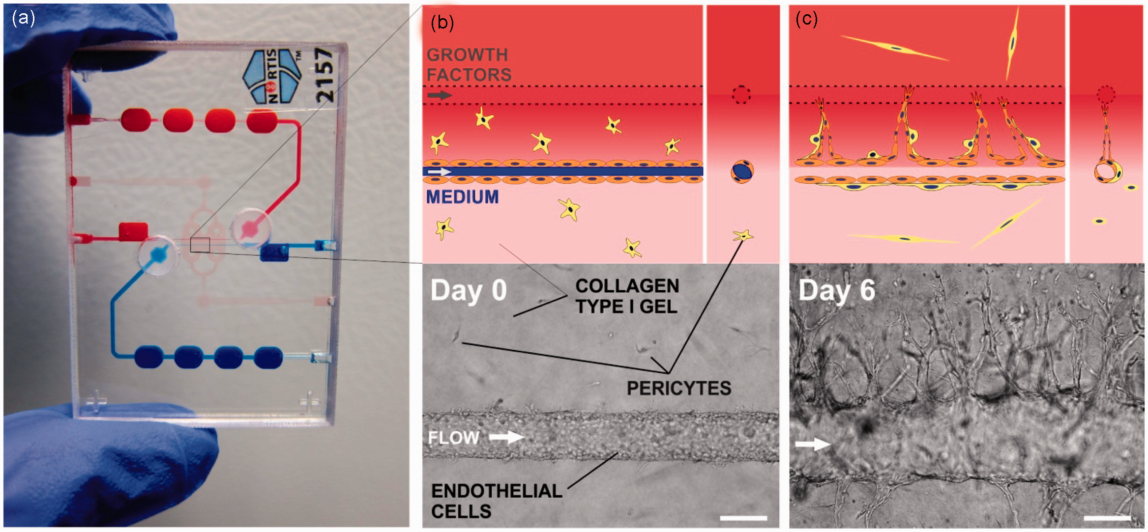
Perfusion of TEMS
The perfusion system consisted of plastic syringes (BD Biosciences) filled with CO2-prequilibrated perfusion medium mounted onto programmable precision infusion-pumps (KD Scientific, Holliston, MA). During perfusion the growth medium was flowed from the syringes via C-flex tubing (Cole Parmer) into the inlets of the vessel-containing perfusion channels, intralumenally through the vessels, and out into reservoirs for fluid collection. The device was stored in an incubator (37℃, 5% CO2) for proper temperature- and pH adjustment. Flow rates were 2 µL/min, which corresponds to 2.09 dyn/cm2.
Cell culture and seeding in chips
All cells were cultured in a humidified incubator at 37℃, 5% CO2. Human umbilical vein endothelial cells (HUVECs, Lonza, Walkersville, MD) were grown in EGM-2 basal medium (Lonza) supplemented with growth factors (EGM™-2 SingleQuot™ Kit Suppl. & Growth Factors, Lonza). Angiogenic sprouting was induced using EGM-2 basal medium supplemented with VEGF (50 µg/mL), basic-fibroblast growth factor (b-FGF) (50 µg/mL), and Phorbol-12-myristate-13-acetate (PMA) (200 µg/mL). Human dermal blood microvascular cells were grown in EGM-2 basal medium supplemented with growth factors (EGM™-2 mv SingleQuot™ Kit Suppl. & Growth Factors, Lonza). Human cerebral microvascular cells (hCMEC/D3, Lonza) were grown in endothelial growth medium 2 (EGM-2) basal medium supplemented with VEGF, insulin-like growth factor 1 (IGF-1), epidermal growth factor (EGF), b-FGF, hydrocortisone, ascorbate, penicillin–streptomycin, and 2.5% fetal bovine serum (FBS; Lonza). For cells cultured inside the TEMS chips, growth-factor-depleted media was used (1 ng/mL b-FGF, 2.5% FBS, 0.55 µmol/L hydrocortisone, and penicillin–streptomycin). Human brain astrocytes and pericytes were purchased from ScienCell Research Laboratories (San Diego, CA). After thawing, cells were grown in tissue culture flasks for two days prior to seeding in microfluidic chips. Pericytes were cultured in pericyte basal medium, 2% FBS, and pericyte growth supplement; astrocytes were cultured in astrocyte basal medium, 2% FBS, and astrocyte growth supplement (all from ScienCell Research Laboratories). For co-culture of all three cell types, EC culture media (EGM-2 basal medium supplemented with growth factors) was used. The human prostate cancer cell lines PC3 and BT-474 were purchased from ATCC and cultured in F-12K medium or DMEM, respectively. In the BBB model, pericytes and astrocytes were embedded in collagen type I gel at concentrations of 100,000 cells/mL by mixing cells into neutralized collagen solution that was incubated on ice for 30 min. The chips were then immediately transferred to an incubator at 37℃ to allow the collagen gel to set. ECs (∼3 × 10⁴) were seeded into the lumen of the chip channels using the cell injection port and allowed to adhere for 30 min. Perfusion was then initiated and unattached cells were removed. In the cancer-cell extravasation model, PC3 or BT-474 (1 × 10³) cells were injected into four-day old EC tubes. Unadhered cells were washed out after 15 min. All EC vessels were perfused continuously using syringe pumps.
Cell staining
Live PC3, BT-474, and pericyte cells were stained with CellTracker™ Orange CMRA (10 µmol/L, Invitrogen, Grand Island, NY) before injection into the vessels. Live HUVECs and astrocytes were stained with CellTracker™ Green CMFDA (10 µmol/L, Invitrogen). For immunofluorescence, cultures were fixed by lumenal perfusion with 4% formaldehyde for 20 min. For CD31 and NG2 labeling, cells were permeabilized with ice-cold acetone for 2 min and blocked in 0.1 mol/L glycine, 1% bovine serum albumin (BSA), and 0.1% Tween 20 in phosphate-buffered saline (PBS) overnight at 4℃. The cells were then washed with PBS and incubated with polyclonal rabbit anti-CD31 antibody (1:40, Abcam) and anti-NG2 mouse monoclonal antibody (1:200, Millipore, Chemicon, Billerica, MA). After washing the chips with PBS, cultures were incubated with secondary antibody (Alexa Fluor dyes conjugated, Invitrogen, 1:250) in the dark at room temperature for 2 h. Cells were then washed with PBS and 4′,6-diamidino-2-phenylindole (DAPI; 10 µg/mL) and imaged with a Nikon TE200 epifluorescence microscope equipped with QImaging EXi Blue camera. For basement membrane protein staining the cultures were fixed by lumenal perfusion with 4% formaldehyde at room temperature for 20 min, washed in PBS, and blocked in 1.25% BSA in PBS for 1 h at room temperature. The cells were then incubated with either anti-collagen IV polyclonal rabbit IgG1 antibody (Chemicon) and anti-laminin monoclonal mouse IgG1 (Invitrogen) or with anti-fibronectin monoclonal mouse IgG1 and anti-nidogen polyclonal rabbit IgG1 (both Millipore Calbiochem) overnight at 4℃. The devices were then washed in PBS and incubated with Alexa Fluor SFX 594 goat anti-rabbit IgG1 and Alexa Fluor SFX 488 goat anti-mouse IgG1 antibodies (1:250 dilution) for 2 h at room temperature in the dark. Cells were then washed with PBS with DAPI and imaged.
Paracellular permeability
The following fluorescence tracers were used: (for solute and ion permeability) Oregon Green (OG; 5 μg/mL; Invitrogen, molecular weight [MW] 376) and Alexa Fluor 488-dextrans (5 μg/mL; MW 3000 and 10,000 Da, Invitrogen); (for protein permeability) Alexa Fluor 594-conjugated BSA (50 μg/mL; 66,000 Da; Invitrogen). Permeability was measured four days after EC seeding. Fluorescent tracers were introduced intralumenally using custom-made glass cannulae. Fluorescence images were taken every 30 s for 10 min after flow was initiated using a wide-field fluorescence microscope and a 10x objective under flow conditions. Background and dark current images were taken before introduction of fluorescent tracers. The effective diffusional permeability coefficient Pd was calculated from the equation Pd = (1/ΔI)(δI/δt)(d/4), 17 where ΔI is the initial increase in fluorescence intensity after filling the vessel with fluorescent tracer; (δI/δt) is the initial rate of increase in fluorescence intensity as the tracer begins to diffuse into the gel, and d is the diameter of the tube. We estimated (δI/δt) by plotting the total intensity of the image versus time and finding the slope during the first 9 min. We conducted control experiments to verify that the fluorescence signal is proportional to the fluorophore concentration in the experimental range.
Image analysis
To calculate permeability using ImageJ, after subtracting the dark current image (camera shutter closed) from the raw images, the resulting images were flat-field corrected by dividing dark-current subtracted images by the blank images (fluorescent standard, also dark-current corrected) on a pixel-by-pixel base. Blank images were taken using identical exposure times and acquisition settings. The resulting flat-field corrected images were re-scaled (multiplied by the mean pixel value of the raw images) and image-wide regions of interest immediately above and below the microvessel were used to calculate diffusional permeability coefficients. We used ImageJ to measure the lengths of individual sprouts in HUVEC vessels co-cultured with pericytes in the presence (N = 9 vessels) or absence (N = 3 vessels) of VEGF. For the quantification of cancer cell extravasation we quantified the number of extravasated cells as the ratio of cells outside of the vessel wall (or channel) boundary to the total number of cancer cells trapped in the sprouts (or empty channel). All results are presented as the mean ± one standard deviation.
Statistical analysis
Data are reported as means ± standard deviations. To compare the means, the unpaired Student's t-test was applied using GraphPad software.
Results
Angiogenesis
To tissue-engineer blood vessels using our technology we injected a mixture of collagen gel precursor and human vascular pericytes into the main chamber of the chips. After gelling, the glass fibers were extracted to generate two channels through the matrix and a parent vessel was created by populating one channel with HUVECs. The vessels displayed many features of in-vivo vasculature, including the deposition of basement membrane proteins and the association of pericytes along vessel walls (Figure 2). To determine whether these vessels could be induced to undergo angiogenesis, the parent vessels were exposed to a gradient of growth factors. The growth factor gradient was generated by perfusing the second channel with an angiogenic cocktail of VEGF, b-FGF, and PMA (sprouting medium). The channel perfused with sprouting medium served as a source for pro-angiogenic compounds and the parent vessel served as a sink, thus creating an interstitial gradient of VEGF/b-FGF/PMA across the collagen matrix. Within one day of exposure to the angiogenic gradient, sprouts began to form, growing towards the growth factors and eventually spanning several hundred microns of matrix (Figure 1). Sprout length was measured one, five, and seven days after exposure to the growth factor gradient. In parallel, the length of sprouts from parent vessels grown in the absence of a growth factor gradient was measured. At all three time points, the sprout length in vessels exposed to a growth factor gradient was significantly different (P ≤ 0.002) than the sprout length of vessels grown in the absence of a growth factor gradient (Figure 2d), indicating that angiogenic sprouting in this system is dependent on the presence of a growth factor gradient. In our model, pericytes were initially evenly distributed in the collagen type I matrix surrounding the parent vessel. Immunofluorescence staining for the NG2 proteoglycan, to identify pericytes, and CD31 for ECs indicated that, similar to what is observed in vivo, pericytes were recruited to developing endothelial sprouts (Figure 2a–c). In fact, pericytes were associated with nearly 100% of the sprouts we observed. EC–pericyte interactions also stimulated basement membrane formation, a structural component of blood vessels and regulator of angiogenesis. Both transmission electron microscopy and staining for the basement membrane proteins collagen IV, laminin, nidogen, and fibronectin indicated that a basement membrane was associated with the parent vessel and angiogenic sprouts of our model system (Figure 2e).
Angiogenesis model recapitulates features of the in-vivo process. Parent HUVEC vessels were created in collagen mixed with pericytes and exposed to a gradient of growth factors for 11 days. (a–c) Co-immunofluorescence indicated that pericytes (NG2, green) were recruited to the parent vessels and associated sprouts (CD31, red; DAPI, blue); (d) Sprouting from parent vessels was dependent on the presence of a growth factor gradient: plot of sprout length in the presence and absence of a growth factor gradient, error bars are mean ± 1 standard deviation (N = 9 vessels, with VEGF; N = 3 vessels, no-VEGF control). Unpaired Student's t-test, 95% confidence interval for VEGF and no-VEGF conditions: t(8) = 4.4, P = 0.0022, t(5)=7.8, P = 0.0005, t(6) = 7.5, P = 0.0003 for days 1, 5, and 7, respectively. (e) Basement membrane proteins were deposited along the parent HUVEC vessel and associated sprouts grown in co-culture with pericytes. Detergent-free immunofluorescence staining. Scale bars are 250 µm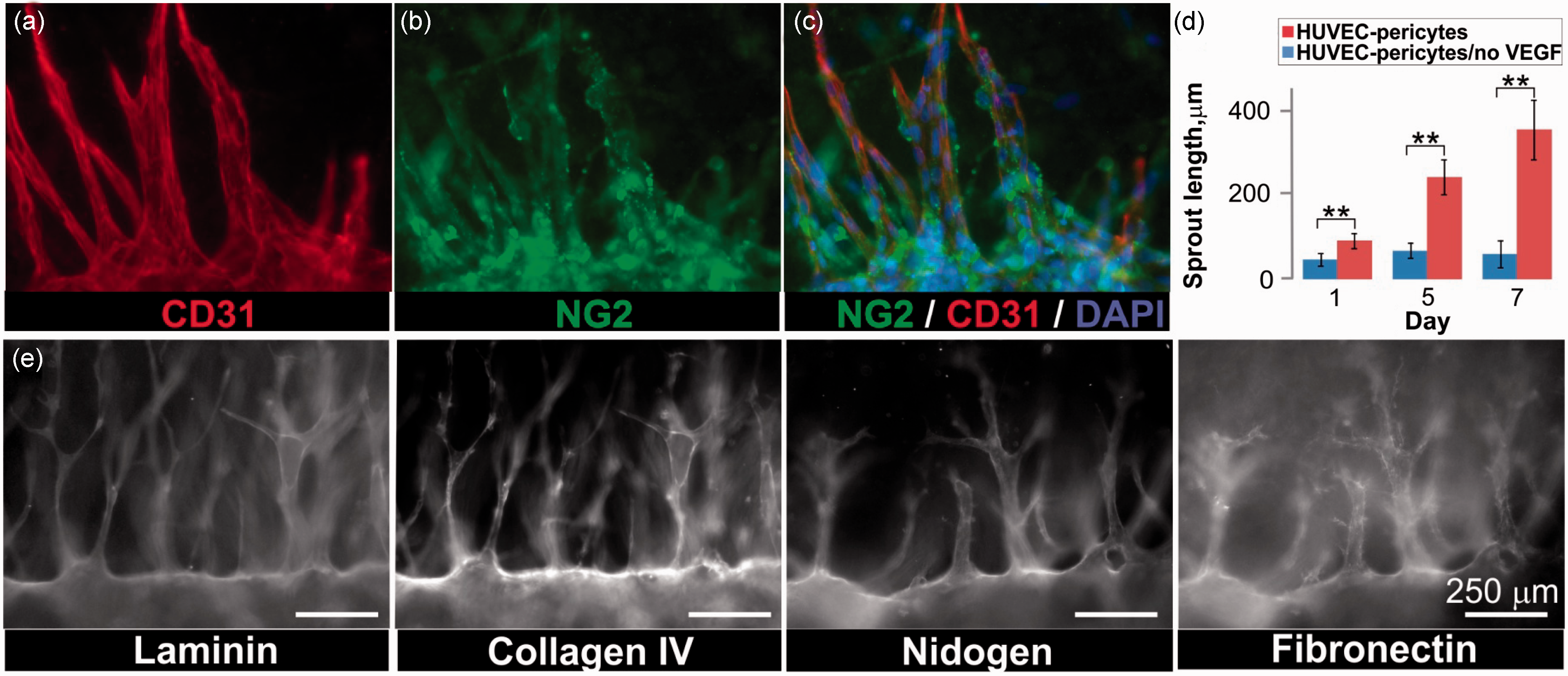
Blood–brain barrier
We also applied our TEMS technology to generate a model of the BBB. Instead of using the dual channel chip described for the angiogenesis model, we used a slightly different version of the chip that only contains a single channel. We embedded human brain astrocytes and human brain pericytes in a 3D hydrogel matrix consisting of collagen type I and, after gelling, populated the tube with immortalized brain microvascular cells (hCMEC/D3) or dermal blood microvascular cells (Figure 3a, b, and d). After allowing the cells to attach, the lumen was continuously perfused. Immuofluorescent staining with CD31 showed complete cellular coverage throughout the tube and correct cell–cell junction formation (Figure 3c). Five days after seeding the ECs, we found that similar to the in-vivo situation, the pericytes and astrocytes had organized themselves along the vessel and were tightly associated with the ECs (Figure 3e). To determine whether the barrier function, assessed as paracellular permeability, of our engineered microvessels was similar to that observed in vivo, we injected BSA (MW 66 kDa) and hydrophilic fluorescent tracer molecules of different MWs (376 Da [OG], 3000 Da, and 10,000 Da) into the vessel lumen and recorded images after 1 min of perfusion. As a control, we made the same measurements in empty channels that were not populated with ECs (Figure 3f). The effective diffusional permeability coefficients were determined as described in “Materials and methods” section. In both the control channels and microvessels, paracellular permeability of molecules increased with decreasing MW (Figure 3g and h). However, in the control channels, molecules 3 KDa or bigger diffused into the surrounding collagen at similar rates. Further, the paracellular permeability was significantly increased (P < 0.0001) in the empty channels relative to the engineered microvessels for every molecule tested (Figure 3h). We found 73% of tested microvessels to be impermeable to BSA, and the average permeability through the microvessel wall was calculated at 1 × 10⁻⁶ cm/s (N = 28), which is comparable to that of isolated mammalian venules.
18
The permeability of engineered microvessels to OG (2.5 × 10⁻⁵ cm/s, N = 22) was comparable to the values reported for rat brain EC–astrocyte co-cultures (1.1 × 10⁻⁵ cm/s).
19
Together, these observations indicate that the barrier function of the engineered microvessels was intact and similar to that reported for other models.
Paracellular permeability in the BBB model. (a) Schematic of the in-vivo human BBB; (b) Recapitulation of BBB features: the vessel wall is formed by ECs with pericytes and astrocytes located in the proximity (oblique illumination image); (c) CD31 immunostaining shows correct localization of cell junctions and complete cell coverage; (d) a microvessel was created from immortalized brain microvascular cells (hCMEC/D3) surrounded by ECM embedded with pericytes (red) and astrocytes (green); (e) Within five days of culture, the astrocytes and pericytes self-organized to associate with the brain microvessel, no retraction of the endothelium from the walls was observed. Scale bars in (c–e) are 125 µm; (f) Brain microvessels and empty channels (control) were perfused with fluorescently tagged BSA and images were taken every 30 s for 10 min; (g) plot of normalized fluorescent intensity (FI) vs. time in the regions adjacent to the microvessel for molecules of different MW; (h) Permeability coefficient for OG (n = 22 vessels, n = 3 control tubes), Alexa Fluor dextrans 3 KDa (n = 13 vessels, n = 3 control tubes), and 10 KDa (n = 18 vessels, n = 3 control tubes), and BSA-Alexa Fluor 594 (BSA, n = 28 vessels, n = 3 control tubes). Unpaired Student's t-test, 95% confidence interval, for the permeability of vessels and controls to all four tracers: t(23) = 9.3, P < 0.0001, t(14) = 7.6, P < 0.0001, t(19) = 13.7, P < 0.0001, t(29) = 14.7, P < 0.0001, for OG, 3 kDa and 10 kDa dextrans and BSA, respectively. Error bars are mean ± 1 standard deviation, scale bars are 250 µm. *Modified after: Abbot et al. Nature Reviews Neuroscience 2006;7:42–53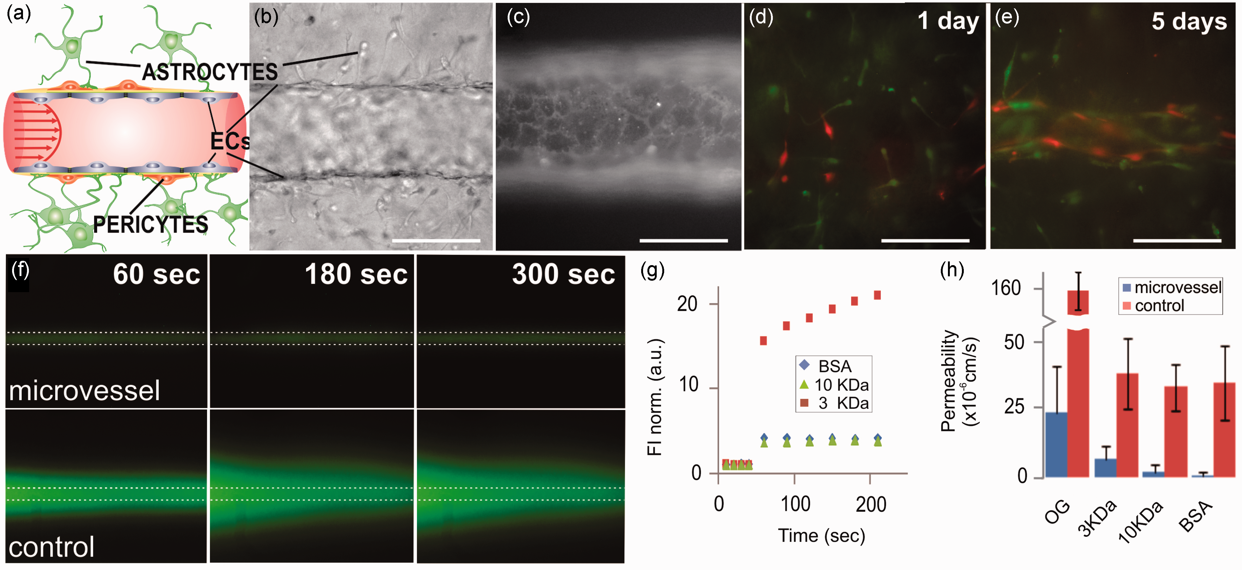
Cancer-cell extravasation model
Using our knowledge from the angiogenesis and BBB models we developed a model of cancer-cell extravasation. This model allowed us to observe cancer-cell migration through the walls of HUVEC-derived microvessels under flow conditions. To generate the model, we first created a sprouting microvessel as described above. Then, a suspension of PC3 prostate (highly metastatic) or BT-474 breast cancer cells (low metastatic potential) was infused into the vessel (Figure 4a). The cancer cells were labeled with a fluorescent tracker in order to distinguish them from the vascular cells. Using standard imaging tools we observed extravasation of the PC3 cancer cells from HUVEC vessels, but not BT-474 cells, consistent with in-vivo observations (Figure 4b and d). As a control, we introduced PC3 cells into empty channels and could not observe any transmigration through the channel walls (Figure 4c). We measured the percentage of cancer cells that migrated through the vessel versus the number of cells that remained inside the vessel. Although we did not observe any significant transmigration of PC3 cells through the empty collagen tube walls (<2%), we found that approximately 40% of the PC3 cells transmigrated through microvessel walls (Figure 4e). In contrast, we were unable to observe transmigration of any BT-474 cells through the microvessel walls, as expected for cancer cells with low metastatic potential (Figure 4e). These data suggest that the metastatic potential of cancer cell lines can be modeled using our TEMS. For drug testing, one could envision a candidate drug being administered directly to the perfusate during the experiment and analysis being performed with standard imaging tools. The efficacy would be determined by measuring the ability of the drug to prevent cancer cells from leaving the vessels.
Cancer cell migration through microvessel walls. (a) Oblique illumination image of PC3 prostate cancer cells that were introduced into a HUVEC microvessel sprout; note the spherical cells marked with arrows. PC3 and endothelial cells were stained with live cell tracker dyes prior to cell injection; (b) 24 h later the PC3 cells (orange-yellow) had transmigrated through the endothelial cell (green) vessel wall into the surrounding matrix; (c) PC3 cells did not transmigrate when injected into empty collagen channels, oblique illumination; (d) no transmigration of BT-474 breast cancer cells (orange-yellow) was observed 24 h after introduction into HUVEC (green) sprouts; (e) plot of the percentage of PC3 and BT-474 cells in HUVEC sprouts that extravasated through the microvessel wall or percentage of PC3 cells in empty channel (control) that migrated into surrounding matrix. Data are plotted as the mean ± 1 standard deviation. (Control: n = 4 channels [3540 total cells in channels]; PC3: n = 5 vessels [167 total cells in sprouts]; BT-474: n = 2 vessels). Scale bar is 125 µm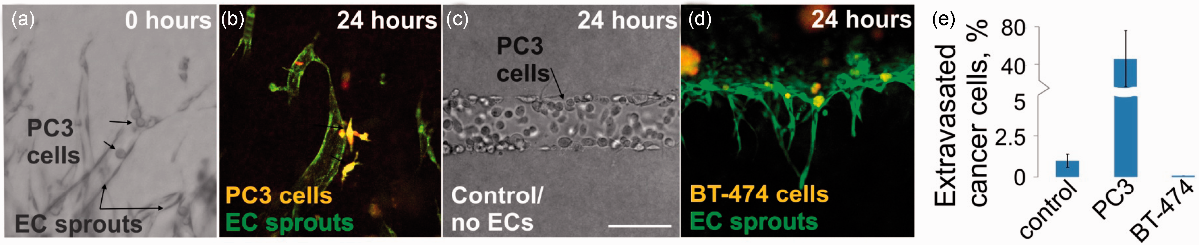
Discussion
We have developed a microfluidic-chip technology that allows researchers to model vascularized microenvironments. Using the TEMS chip we can grow perfusable 3D tubular structures that are completely surrounded by a supporting ECM. The lumenal and extralumenal compartments can be independently perfused and do not require any artificial scaffold materials. Utilizing this chip we have generated three vascular models which we describe in this brief communication. We present data highlighting in-vivo features of three vascular systems that can be recapitulated using our microfluidic technology.
We created “parent” microvessels that undergo angiogenesis in response to a gradient of growth factors (Figure 1 and Figure 2d). Similar to what is observed in vivo, pericytes, initially embedded in the surrounding matrix, organize themselves and closely associate with the growing microvasculature (Figure 2a–c). Additionally, we developed a model that mimics the BBB. The BBB is the key structural element in controlling the passage of drugs, nutrients, fluids, and metabolic products between the blood and the central nervous system. Impaired function of the BBB plays a pivotal role in major diseases, such as Alzheimer's disease,20,21 multiple sclerosis,22,23 Parkinson's disease,24,25 malignancies of the brain,26,27 and stroke, 28 and research models that better mimic the BBB promise the discovery of new therapeutic opportunities. The paracellular permeability values in our BBB model were similar to those reported for isolated human venules, 18 indicating comparable barrier functions between our model and in-vivo tissue (Figure 3). The third vascular model we described recapitulates the extravasation of cancer cells through the walls of microvessels—a crucial, but poorly understood, step of the metastatic cascade. Metastasis is responsible for more than 90% of cancer-associated mortality. Thus, there is a large interest in understanding this process and a need for developing metastasis-inhibiting drugs. Current models lack the ability to recapitulate the in-vivo interactions between circulating tumor cells (CTCs), stroma, and vasculature in a 3D environment. Using our microfluidic chips, we developed sprouting microvasculature that was then utilized to study the migration of prostate cancer cells through the vessel walls into the surrounding matrix. Similar to the in-vivo situation, highly metastatic PC3 cells could transmigrate through microvessel walls, but cancer cells with low metastatic potential (BT-474) could not (Figure 4). Once established, the model could be utilized to identify how compounds, different cells, or mechanical forces impact extravasation activity.
In this brief communication we presented models focusing on the human microvasculature. However, our technology applies to other tubular tissues as well. Using our TEMS chips, and in collaboration with other research teams, our group is developing several organ microenvironments, among them a model of the proximal tubule of the human kidney. 29 This effort is part of the “Microphysiological Systems” initiative by NIH (NCATS), which envisions the development of a platform that has the capability of integrating various organ microenvironments for basic research and toxicology screening. The results presented in this brief communication demonstrate the utility of our TEMS technology in creating functional tissue-specific vascularized microenvironments. Future work is focused on advancing these models into validated assays that can be provided to the research community.
Footnotes
Author contributions
AT, MF, and TN participated in the experimental design and AT and GK participated in the acquisition of data. AT, MF, TN, and SS analyzed and interpreted data. SS and TN drafted the manuscript. TN, AT, MF, and GK reviewed the article for content. All authors approved the submitted version.
ACKNOWLEDGEMENTS
The authors thank Ms Elizabeth McClure for her help in manufacturing the TEMS chips. This work was supported by the National Institutes of Health (NIH)/National Heart, Lung, and Blood Institute [SBIR Phase I, 1R43HL107040-01A1]; the NIH/National Institute of Neurological Disorders and Stroke [SBIR Phase I, 1R43NS070440-01]; the NIH/National Cancer Institute [SBIR Phase I, 1R43CA144469-01]; and the NIH Common Fund/National Center for Advancing Translational Science [UH2/UH3, 1UH2TR000504-01]. All authors are current or former employees and stockholders of Nortis, Inc.