
Abstract
In this article, the cognitive vision module of an autonomous flying robot is studied. The problem of the scene understanding by the robot, which flies on the high altitude, is analyzed. In such conditions, the examined scene can be regarded as two-dimensional. It is assumed that the robot operates in the urban-type environment. The scene representation is stored in the neighborhood graph that collects data about the objects locations, shapes, and their spatial relations. The fragments of the scene are understood by the robot in the context of neighborhoods of the objects. It is shown that such information can be effectively used for recognition of the object, while many objects of similar shape exist in the scene. In the proposed recognition process, not only the information about the shape of the object is utilized but also the spatial relations with other objects in its close neighborhood are examined.
Introduction
Autonomous mobile robots have to be equipped with a system of sensors connected with a cognitive module that processes the signals obtained from the sensors. In such a context robot, vision systems have been studied for years—the research by Bonin-Font et al. 1 and Tadeusiewicz 2 can be put as examples. Such systems have special meaning for autonomous robots, including unmanned aerial vehicles (UAVs). In an unknown environment, cognitive abilities such as the object recognition, 3,4 the scene analysis, 5 –9 and its understanding are indispensable (see the work done by Bielecka et al. 10,11 and Tadeusiewicz 12,13 in the context of medical image understanding). Therefore, systems of pattern recognition and scene analysis based on vision systems have been studied intensively in robotics in the context of scene understanding and the positioning of a robot. 14 –18
Most of the approaches presented in these studies have specific specializations which force utilization of different algorithms and techniques. Comparing the method presented in this article to those discussed in the studies by Siagan and Itti 17 and Sinopoli et al. 18 , it can be used to model not only the overall shape of the scene or its salient features but to create, store, and process the models of specific artifacts located in the examined scene—like buildings, cars, and so on. Modeling and keeping the information about the shapes of objects discovered in the scene creates the possibilities for precise close-to-object navigation, essential for inspection tasks. The advantage over most of the methods described in the literature by Filliat and Mayer 14 Yershova et al., 15 and Muratet et al. 16 is the utilization of graph data structure to store all the information about the scene that is collected by the UAV during the operation. Such approach has various benefits. For example, the scene model can be represented in human readable way for further analysis as well as for easy analysis with graph algorithms (like subgraph search presented in this article used in localization algorithm).
In this article, the module of two-dimensional scene analysis, which can be applied for use by a UAV, is proposed. The presented studies are a continuation of the investigations described in the studies by Bielecki et al. 19 –21 In particular, the detailed description of the state of the art and motivations can be found in the study by Bielecki et al. 20
The problem formulation
Let us recall briefly the specification of the problem formulation—see the study by Bielecki et al. 20 for details.
Let us consider a UAV that operates in an urban environment. The analysis of the mission scene—localization of a specific building and studying the properties of the scene—is one of the agent’s tasks. Let us assume that the agent’s memory contains the map, which is given a priori. Furthermore, let the robot be equipped with the mobile camera that is able to point to the ground in order to take the pictures of the surface above which it operates. The map that the robot carries in memory presents the buildings extracted from the background. By referring to the given two-dimensional map and the two-dimensional image from its sensors, the agent compares the extracted shapes of the buildings and orients itself in the environment. Such task is fundamental for a UAV in order to conduct safe and robust navigation.
22
The method of the objects recognition has to be rotation and scale invariant as the pictures of the ground are taken from different altitudes and various directions of the robot’s flight. Then, the robot descends in order to explore the environment directly using a camera or other types of sensors, like a single-point directional rangefinder or an light detection and ranging (LIDAR) system. The close exploration of the environment allows the agent to create its three-dimensional representation. As a result, the desired object can be located, and the robot gets better understanding of the surrounding area. Thus, the studies can be divided in the following stages: Creation of a single, two-dimensional object representation based on the camera image taken from high altitude. Creation of the overall two-dimensional scene representation based on the camera image. This step allows the robot to recognize the recorded scene as a fragment of the arbitrarily given map. The single desired object, marked on the map, should be recognized. Obtaining a three-dimensional representation of the scene fragments based on the calculated two-dimensional scene representation. The two-dimensional representation allows the agent to locate the buildings. When their localization is known, the robot can investigate individual objects in order to create their three-dimensional representation. Understanding the three-dimensional scene.
The second point from the list is the topic of this article. While such scenario can also be related to the search for landing position which is widely studied, 23,24 the investigation presented in this article focuses more on universal method of shape recognition. It allows to find the particular shape among multiple similar shapes in the scene. This is accomplished by incorporating idea of spatial relationship between objects into the recognition process.
In the article by Bielecki et al., 20 the authors focused on single object analysis, and the two-dimensional scene analysis was addressed only initially. This article is a continuation of this research. Here, the problem of scene analysis is described in detail.
Algorithm
The scene analysis in this article is aimed to develop a model of area that enables the robot to, in later steps, conduct search of selected object in real environment. It is important to note that when coordinates are mentioned in terms of object or scene representation, the authors mean the Euclidean coordinates of object with respect to the frame of image taken as an input for the algorithms. It means that point (0,0) of the Euclidean space is in the bottom left corner of the input image.
The following scenario is presented to give the notion of how the proposed algorithms work and what is their sample application: The flying robot’s task is to find the building in real environment. A bitmap picture representing the scene photographed from high altitude is used as a reference information. The image is not taken by a robot itself, but it is provided in the form of previously prepared data and is being used by the robot during investigation of the area. As the preprocessing methods are outside of the scope of this article, it is assumed that input data is already a prepreprocessed image. It consists of a group of well-separated, contrasting objects (buildings). Provided bitmap image is vectorized to obtain vector data representing objects shapes. Representation of single object is a sequence of points on Euclidean plane, highlighting the corners of buildings. The algorithm of neighborhood graph (later addressed also by graph) construction is executed on vectorized picture to obtain relation-based representation of a scene. One object which a robot has to find is given as an input and will be later referenced as marked object. This particular graph, based on the provided bitmap image, covering overall investigated area will also be addressed later as reference graph. During robot’s operation, it takes several pictures of the area beneath. Each picture is vectorized, and neighborhood graph is calculated for each of the pictures. The graphs carry information about the relation between objects in fragments of the investigated area. These pictures and graphs will be referenced later by input picture and input graph to distinguish it from reference graph. Syntactic algorithm is used for searching marked object in currently examined graph. Once the object is found, its neighborhood is compared with the neighborhood of marked object to check if the spatial context of found one is similar to the marked object (the idea of spatial context is described in the section “Neighborhood graph construction”). If all close objects of the marked object are found in examined graph and spatial relation with the marked object reflects the spatial relation of objects around the found one, it is assumed that the marked object was found in real area. If not all close objects around marked one are found in the examined picture, it may be the case where missing ones are outside of examined picture. To search for the rest of the objects, the robot takes a wider picture (from higher altitude), and the previous step is repeated for the new picture.
It may also happen that marked object has a duplicate in the reference image—which means that another object of similar shape has spatial context which is exactly the same. Such situation would lead to incorrect results of the search method. To discover the duplicates, a precheck of neighborhood graph is executed before the search process. If the duplicates of marked object are found in the original reference graph, the graph is extended to capture wider spatial context and makes the context more unique for each object. It is done in the manner: “neighbor of my neighbor is my neighbor.” The same extension is applied to the graphs obtained from input pictures along the whole process of searching, and the recognition algorithm uses extended graphs the same way as the basic, not extended graphs would be used.
Vectorization
Vectorization algorithm was described in detail by Bielecki et al. 19 –21 This algorithm allows to obtain a memory-efficient vector representation from preprocessed picture. Input for this method is a bitmap picture with distinctive shapes, representing objects (buildings) that will be subject for later examination. Such picture can be a result of preprocessing executed on image from the robot’s camera during the investigation of a given area. The result of the algorithm consists of a set of objects’ vector representations. Each vector representation is a sequence of points in Euclidean space, located in the border of the shapes. When extracting objects (buildings) from the bitmap, it is necessary to obtain accurate representation of their shapes from the input picture. The desired, accurate representation is the one, where points in the sequence represent coordinates of the corners of extracted object. This is essential for proper recognition of shapes taken from both reference image and examined one. 19,20 The examples of both original and vectorized pictures are shown in Figure 1.

(a) Input for vectorization; (b) vectorization result. Coordinates calculated with respect to the bottom left corner of the picture.
Neighborhood graph construction
Neighborhood graph is a data structure designed to store the scene representation. It collects data about objects locations (coordinates of their centroids), shapes (their vector representation), and their spatial context. The context is defined by the list of objects that are in close neighborhood. The input for graph construction algorithm consists of a set of vectorized objects. For each object in the set, a list of buildings located in close neighborhood are found in this set. It is accomplished in a following manner for currently processed object A: The distance is measured from the centroid of the object A to the closest corner coordinates from the rest of the objects in the scene. The object B, which has corner that is closest to A, is found. The object B is added to the closest neighborhood list. A range r is calculated as a distance from the centroid of A to the farthest corner coordinate of object B. The set of objects is searched again. Each object having at least one corner coordinate lying within the range r from object A centroid is added to the close neighborhood list.
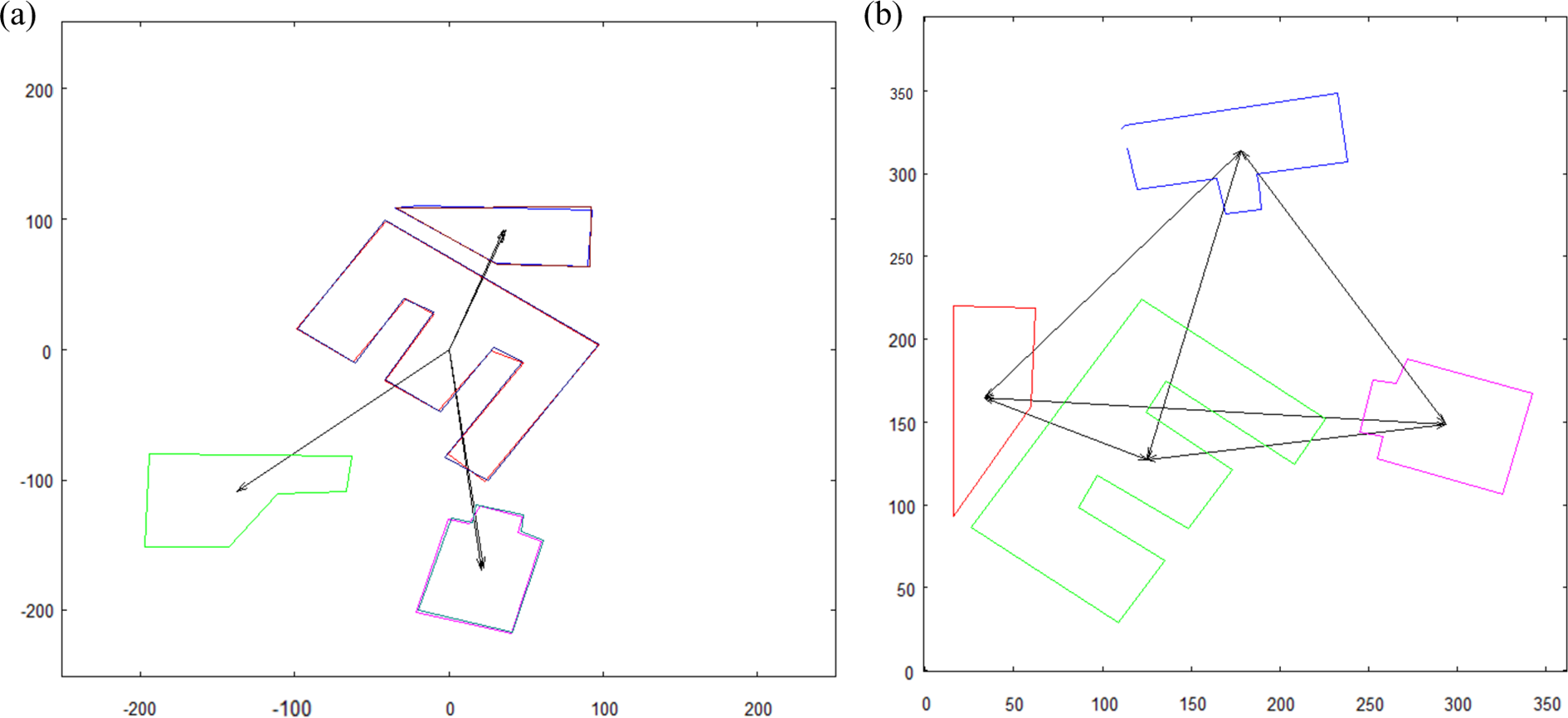
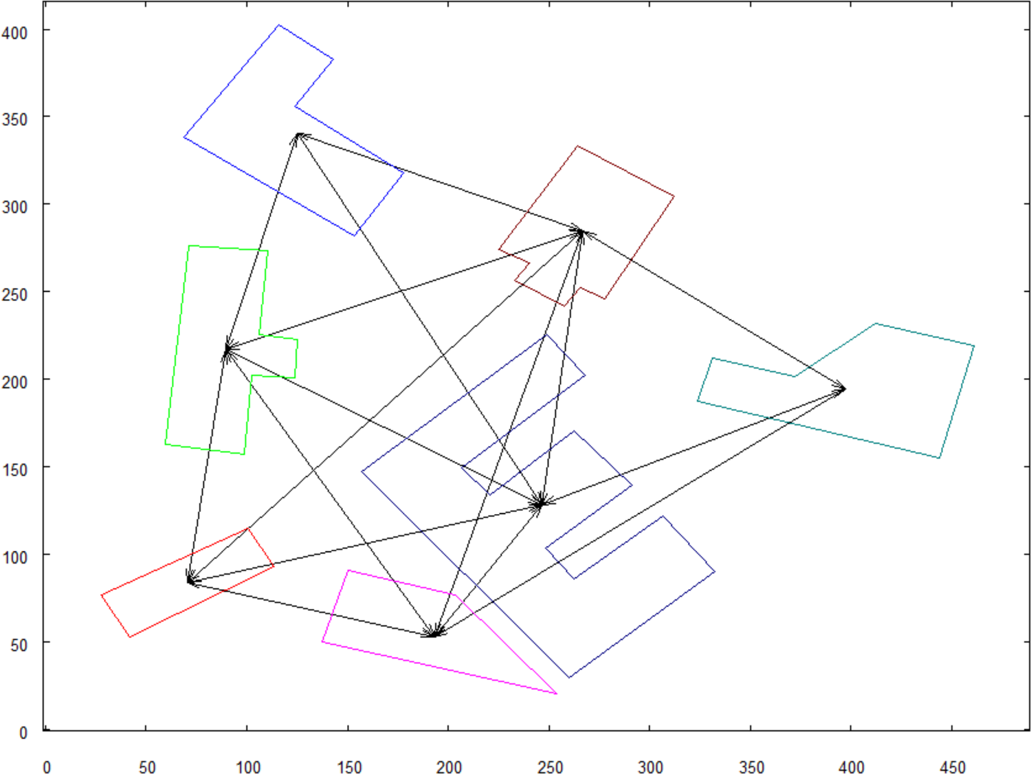
The method of finding the closest neighbors is illustrated in Figure 2(a). The final graph structure is presented in Figure 2(b).

(a) Neighborhood graph construction with one object as an example; (b) result graph.
For the purpose of further calculations (like searching the graph), the centroid of each object is stored in data structure along with the representation of each original object and those in the closest neighborhood list. A part of the neighborhood graph data structure (see Figure 3) collects spatial context of object A, shown in Figure 2(a).
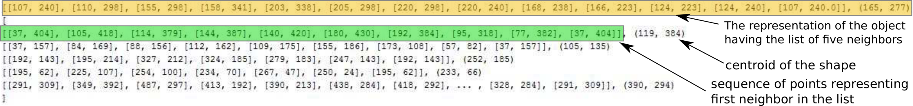
Neighborhood graph structure part.
Search method
Based on the neighborhood graph and the notion of spatial context of an object, the search algorithm was designed. It is aimed to search an object, selected from one graph, among the objects from the second graph. In our proposed scenario, one object (marked object), along with its closest neighborhood list, is picked up from the graph G1 (reference graph). Then, the second graph G2 is searched for objects that represent the same shape and have similar closest neighborhood. The shapes are compared regardless of scale and rotation difference. This algorithm allows to conduct the search which is contextual. This means that not only the shape of the object but also its spatial context is compared. The search is conducted in the following steps: First part of this method is the search of the object selected from G1, in the set of objects from graph G2, not taking the spatial relations into consideration at the moment. For this step, the recognition algorithm described in the studies by Bielecki et al.
19
–21
is used. It allows the recognition of the shape of one object among the set of other objects, regardless of differences in scale and rotation that can be a result of different angles and distances from which the original pictures were taken by a robot. The rotation and scale-invariant matching and data representation used in that algorithm are shown in Figure 4. Representation prepared for recognition algorithm holds information about the angles between successive walls of the building and lengths of these walls. Using the angles between walls helps us to avoid influence of rotation difference between compared objects. As the output of vectorization algorithm is composed of a sequence of points located in the corners of the shape, the actual number of walls can be identified directly by the number of these points (each two subsequent points constitute a single wall). If the number of walls is the same in both objects, the angles between successive walls are compared. The idea is to find the corresponding corners of the shapes that is accomplished by analyzing the sequences of angles between successive walls of each object. Due to possible rotation difference between objects, the starting point in the representation of one of the object can be located in different corners of the shape than in the second object. Thus, the match between the objects’ corners is searched iteratively, taking subsequent point of the second object’s representation as the starting point. When, in some point during iteration, the angles between walls match in both compared objects, the proportions of lengths of each matching pair of walls are calculated. The proportions are measured instead of directly comparing the walls’ lengths because, as it was previously mentioned, the objects may differ in scale and, as a result, all their corresponding walls may differ in length by some ratio. If standard deviation of the calculated proportions remains within given threshold for all the compared pairs of walls, then it is assumed that the match between objects has been found. When the object Objfound is recognized, two factors are calculated to be used in further processing. First is the ratio by which the walls differ and will be referred as scale factor—Sfactor. Second, the rotation factor,Rfactor, is equal to the angle between the first found pair of corresponding walls from two compared objects. This factor tells by what angle the whole shapes are rotated relative to each other. The marked object from G1, with the objects in its closest neighborhood, is transformed and slipped to the point (0, 0) of the coordinate system. Each point of these objects is recalculated as (x1 − xcentr, y1 − ycentr), where x1 and y1 are x and y coordinates of the point which is transformed, whereas xcentr and ycentr are the coordinates of the centroid of marked object—see the result in Figure 5. The object found in G2 (Objfound), along with the objects in its closest neighborhood, is also transformed in the way described in the previous point. The centroid of the found object Objfound is used for calculation of new coordinates values. The object Objfound and neighbor objects are scaled and rotated using previously stored Sfactor and Rfactor. The final step is to check if the corresponding objects from the closest neighborhood of marked object and Objfound are located in the same place in the coordinate system. Furthermore, it is checked if the coordinates of their corners are close to coordinates from the corresponding object. Transformed objects with their neighborhoods are shown in Figure 6. It can be observed that the corresponding objects overlap. This means that the complete matching has been detected, that is, all neighborhood objects are recognized.

Representation used for syntactic algorithm of object matching. Example of match found between two objects.

Marked object from G1 with its neighborhood transformed.

Marked object from G1 with its neighborhood transformed.
Results
The following tests were executed to cover different situations mentioned in the scenario from the beginning of the previous section.
Incomplete match
The first test was executed for input picture that does not show complete area with marked object’s spatial context—see Figure 7. This results in an incomplete match where marked object was found, but not all objects from the close neighborhood can be recognized—see Figure 8. Factors calculated in this test—Sfactor = 0.67 and Rfactor = 83°.

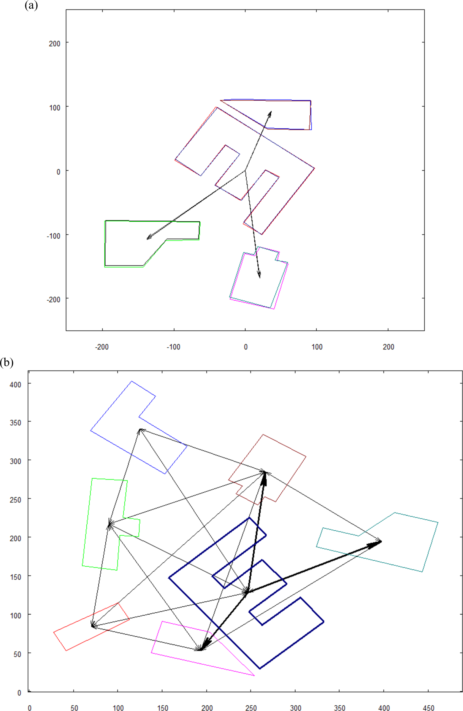
(a) Visualized graph structure with the object to be searched—highlighted with the thick lines; (b) graph constructed from input picture where marked object is searched.
(a) Two translated objects, marked and found, with their neighborhood. Partial match found in searched graph. Note that one neighbor object from reference graph was not found. (b) Input graph with recognized objects.
Complete match
In order to increase the confidence of the matching which was found by the robot, a bigger picture is used. It would be the best if the complete spatial context of the searched object were recognized. Such case is shown in Figures 9 and 10. Note that the reference map is the same as in Figure 7(a), only the input image is changed to one that covers wider area. Factors calculated in this test—Sfactor = 0.52 and Rfactor = 165°.
Graph constructed from input picture where marked object is searched.
(a) Two translated objects, marked and found, with their neighborhood. Complete match found—each object from the neighborhood has its corresponding object found in the input picture; (b) input graph with the recognized objects.
Duplicate of marked object
In Figure 11, there is a marked object that shares the same spatial context with other object in graph. To make spatial context unambiguous, the graph is extended in the manner where “neighbor of my neighbor is my neighbor.” The results are shown in Figure 12. It can be observed that the graph became much more complex, and the spatial context for each object is more unique. The input graph is also extended. The graph before and after extension can be seen in Figure 13. Factors calculated in this test—Sfactor = 0.96 and Rfactor = 0°.
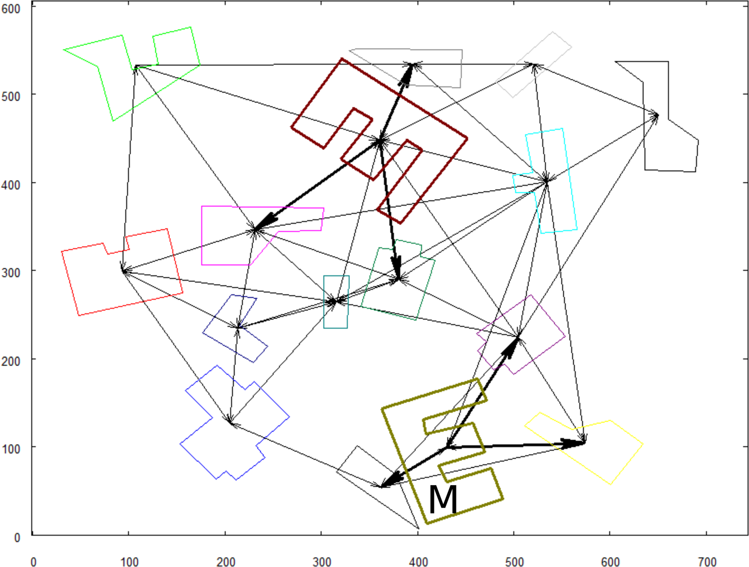
Reference graph with the marked object (signed with “M”) that has a duplicate with the same spatial context.

Extended reference graph. The marked object signed with “M.”

(a) Graph of the input picture before extension; (b) result of the extension of neighborhood in “neighbor of my neighbor is my neighbor” manner.
The marked object was recognized in the input graph. The full matching has not been found because the input image covered smaller area than the range of all neighbors of the marked object. The results are shown in Figure 14.

(a) Two translated objects, marked and found, with their neighborhood. The partial match found, indicated by the group of objects having a pair and three not paired; (b) input graph with the recognized objects.
Discussion
In section “Algorithm,” in suggested scenario, it was stated that precheck is executed on the neighborhood graph to check if marked object has a duplicate with respect to its spatial context. The graph is then extended to obtain more descriptive representation of the neighborhoods of the objects. It can be observed that this solution is sufficient for the situation where the picture taken by the robot during the searching of the area also contains duplicates in nonextended graph. It is so, because the graph related to the image that has just been taken also undergoes the process of extension. In this situation, the spatial context of the objects on the examined picture is no longer ambiguous, just like it is not for the marked object. As a result, the marked object can be found effectively in input picture. The extended neighborhood graph is more complex than the original graph and by that, the spatial context of each object is far more descriptive. This can lead to the conclusion that even if the match found by the use of the extended graph is not complete, it gives enough confidence that the object recognized in the input picture is the one which was initially searched. The presented experimental results are based on previously prepared and preprocessed images. Currently, the authors are working in the project whose aim is to conduct the experiments with the real UAV—the quadcopter equipped with a camera. The tests will be executed in the environment outside of the laboratory with a set of models of buildings. The size of the models is estimated to be around one-tenth of the size of regular two-story buildings and the model is planned to cover 100 m2 of the area. In such arrangement, the robot will climb up to 20 m above the ground to collect the picture of the scene. Initial tests show that from such altitude, the view of the models on the ground can be treated as two-dimensional.
Concluding remarks
In this article, the graph-based approach to a scene representation and recognition was presented. In the previous investigations, 19,20 the authors presented the approach to two-dimensional shapes recognition. Recognition of a group of objects was studied, as well. Those studies, however, were not focused on a scene representation and understanding. In the current study, the neighborhood graph was introduced that constitutes the data structure aimed to provide an informative scene representation for the autonomous robot. The proposed data structure holds spatial information about the scene where close objects are related to each other. The nodes of the graph collect data about the scene objects, their shapes, and locations. The neighborhood graph also constitutes a base for a recognition of the objects with high level of certainty. The object from one graph is searched among objects in another graph with their close neighborhood taken into account. The recognition process is based on comparing not only the shape of the searched object but also its spatial relations with those objects that lay close to it. The experiments showed that different levels of certainty of the searching can be achieved when the robot obtains various images of the investigated scene. The desired level of certainty will differ from one application to another. When the robot is required to find the object in the scene with complete confidence, it has to collect a wider image of the scene. In such image, the searched object should be visible with the complete set of close objects from reference graph. To accomplish this, it would be required for the robot to climb up to higher altitude when taking the picture of the scene. The other way to fulfill this requirement would be to collect a series of pictures covering smaller parts of the area and then combine them into a single image.
Footnotes
Declaration of conflicting interests
The author(s) declared no potential conflicts of interest with respect to the research, authorship, and/or publication of this article.
Funding
The author(s) received no financial support for the research, authorship, and/or publication of this article.