
Abstract
In this article, the comparison of energy performance between a classical and an improved Trombe wall of a model test room has been carried out experimentally. The case study is conducted in Borj Cedria, Tunisia, where there is always heating requirements. Here, we propose an improved Trombe wall whose absorber wall is covered with a thin black copper panel backed rather than simply painted black wall. The proposed idea would offer improved thermal performance, especially in natural convection. The comparison shows that the improved Trombe wall design gives an increase for both conductive and convective flux. The results show that the improved Trombe wall works more effectively than the classical Trombe wall system in utilizing solar energy for the example of test room.
Introduction
At present, the building sector in Tunisia is the largest energy consumer, mainly used for heating and cooling, and it is expected to be the first energy consumer by 2020 (Agence Nationale pour la Maitrise de l’Energie (ANME), 2004). Therefore, we need to actively seek for efficient methods and technologies based on renewable sources to reduce fossil energy consumption.
A Trombe wall is an important green architectural feature that aides the heating, ventilation, and cooling of buildings (Hirunlabh et al., 1999). A classical Trombe wall comprises a massive wall painted black, an exterior glazing, and a ventilated air gap in between (Chan et al., 2010). Two vents at the massive wall are designed for air connection with the indoor. The blackened massive wall absorbs and stores the solar energy transmitted through the glazing. The absorbed heat is partly conducted through the wall to the indoor by convection and radiation, and it is partly transferred by air circulation through the vents due to buoyancy effect (Akbarzadeh et al., 1982). Trombe wall has been widely investigated in the last two decades, for the main reason of its direct application in buildings, essentially in the Mediterranean climates, where solar energy is abundant. It is simple, economical, and suitable to a wide range of latitudes, but its drawbacks have limited its spread so much that it needs to be well designed or improved (Chan et al., 2010). For this purpose, Scientifics inspired several variants of Trombe wall, which usually evolve in function of the climatic need and proved their efficiency as passive heating systems. Many theoretical and experimental studies (Özbalta and Kartal, 2010; Smolec and Thomas, 1991) have even shown that indoor comfort is improved due to well-designed Trombe walls. By installing adjustable dampers at the glazing and adjustable vents of the wall, the classical Trombe wall can be beneficial for winter heating and summer cooling (Gan, 1998; Jie et al., 2007a). Matuska and Sourek (2006) found that there was no effect on indoor comfort when sufficient insulation layers were applied on the storage wall. Stazi et al. (2012) carried out a series of monitoring campaigns in different seasons and dynamic simulations with the software EnergyPlus in order to investigate the Trombe wall’s thermal behavior. Apart from that, energy and air movement in the channel of a Trombe wall are induced by natural convection. Thus, the design parameters of Trombe wall channel are also factors that might affect the convection process (Gan, 1998). A parametric study has shown that airflow rate was almost unaffected by channel width; however, airflow rate was increased with the height of the wall (Onbasioglu and Egrican, 2002). Various modified aspects concerned the essential features of Trombe wall such as air vents control, storage wall characteristics (e.g. thickness, density, presence of fluid circulation, or phase change materials (PCM)), or the glazing type (e.g. simple or double, treated surface, or noble gas). Many researchers were interested to the structure renovation of the Trombe wall system and showed that the modified Trombe wall works more effectively than the classical Trombe wall. For example, the concept of composite Trombe–Michel wall which adds an insulating wall to the classical wall at the back of the massive wall has also been widely studied to overcome the heat loss from the inside to the outside of building (Shen et al., 2007a, Shen et al., 2007b; Zalewski et al., 1997). Duan et al. (2016) have studied the thermal performances of two types of Trombe walls through a mathematical model, depending on the position of an absorber plate on the storage wall. They concluded that the particular exergy destruction due to absorption of the absorber plate is the largest, and that a higher absorber plate temperature is preferable in decreasing the total exergy destruction and increasing exergy efficiency.
In order to improve the aesthetical aspect of the classical Trombe wall, another Trombe structure with photovoltaic (PV) cell module known as a PV-Trombe wall was designed by Jie et al. (2007b and Jie et al. (2007c)). Jiang et al. (2008) have investigated, using a simulation program, the electrical performance of PV cells and the thermal performance of PV-Trombe wall in different coverage ratio. Furthermore, Sun et al. (2011) have conducted an experiment to study the temperature field of a building with both southern facing window and the PV-Trombe wall and developed a dynamic numerical model for the simulation of the whole building system.
Another innovative design of Trombe wall is filling PCM into the masonry wall to store the latent heat. For a given amount of heat storage, the phase change units require less space and are lighter in weight compared to mass wall (Tyagi and Buddhi, 2007). Studies indicated that concrete–PCM combination Trombe wall could be used to develop low-energy house, as it is an effective energy storage wall (Onishi et al., 2001; Uros, 2003). Recently, Zhou and Pang (2015) have performed experiments on the thermal behavior of a PCM Trombe wall system with heat transfer enhancement by delta winglet vortex generators (DWVGs). They indicated the advantages of using longitudinal vortex generators to improve the performance of PCM Trombe wall systems for passive solar heating.
Nwachukwu and Okonkwo (2008) have found that applying a coating of superior absorption vigor on the exterior of storage wall could enhance the heat absorption and transfer across a Trombe wall. In another study, Dragićević and Lambic (2011) presented an efficiency analysis of the modified Trombe wall with forced convection, which can operate in four different modes. An improved Trombe wall is proposed to be adapted to building construction with selective thermo insulation façades in China (Jie et al., 2009). The results show that the operating efficiency of the improved Trombe wall can be up to 33.85% with an increase of 56%. The work of Jie et al. (2009) has neglected numerically the conduction process through the wall by inserting an insulating layer behind the steel panel. Recently, He et al. (2016) have carried out a two-dimensional computational fluid dynamic (CFD) analysis to determine the flow and heat transfer of a novel Trombe wall with venetian blind structure. They indicated that smaller slat angle helps to enhance the outlet air temperature and solar thermal efficiency, while increasing the Reynolds number leads to decrease in outlet air temperature and increase in solar thermal efficiency.
For different climates, many researchers have studied the thermal performance of the Trombe wall. Hernández-López et al. (2016) have presented a thermal evaluation of a room with a Trombe wall in two cities of Mexico with cold climate (Huitzilac and Toluca). They affirmed that thermal energy losses through the semitransparent wall are about 60% of the solar radiation incident on the system, which permits to keep the air inside the room with a temperature above 35°C. Rabani et al. (2015) studied a new designed Trombe Wall for Yadz, Iran, in winter. From the comparison of numerical and experimental results, the authors concluded that the new design of Trombe wall is able to keep the room warm. Bajc et al. (2015) presented a three-dimensional numerical analysis of temperature fields in Trombe wall and in the adjacent room for Belgrade, Serbia, weather. They simulated temperature fields in concrete core and in the room with Trombe wall, as well as velocity fields, and they performed an analysis of energy savings potential.
Based on the absorptive property of the exterior wall, the aim of this study is to maximize the absorption potential of a Trombe wall system depending on an exterior coating. In addition, the provision of an exterior coating of the wall improves and accelerates the heat transfer and the storage processes. In this context, an experimental study is presented to evaluate the thermal performance of an improved Trombe wall by a comparison with a classical Trombe wall, under Tunisian weather conditions (Dimassi and Dehmani, 2012). In fact, the absorber wall is covered with a thin black copper panel backed rather than simply painted black wall. The surface has been engineered to optimize the properties required for enhancing solar thermal energy collection.
Experimental setup
Case study
The experimental setup is a simple room with Trombe wall on its south side, located at the Center of Research and Technology of Energy in Borj Cedria (CRTEn). Experiments were performed under Borj Cedria weather conditions, located in 36°43′04″N, 10°25′41″E. It is characterized by a mild humid climate with a yearly average ambient temperature about 18.6°C, fluctuating from a maximum of 42.4°C to a minimum of 1.3°C. The solar radiation is abundant round the year with strong sunshine, the maximum solar intensity on horizontal plane exceeds 1108 W/m2, and the yearly average solar radiation is 196 W/m2.
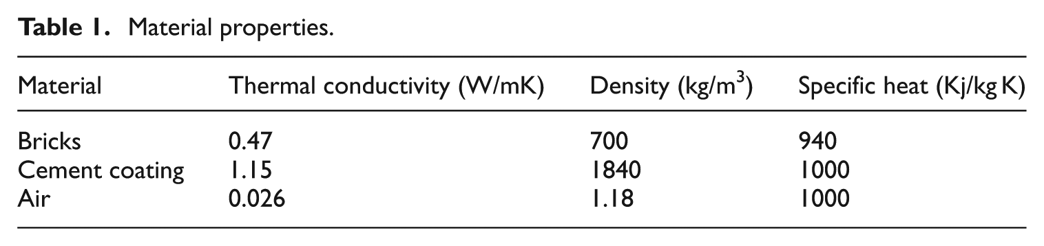
The experimental test room has been designate to evaluate performances of classical and improved Trombe wall systems. It is a wooden room with the dimensions of 1.86 m × 1.52 m × 1.52 m (Figure 1). The walls and roof of the test room are well insulated and made of 0.4-m-thick polystyrene boards to avoid heat losses. The Trombe wall consists of 0.10-m-thick storage wall, made up of solid concrete bricks and covered by a cement coating (Table 1). The heat absorbing wall surface was painted black matt. An insulating panel was placed around the sides of the storage wall to reduce lateral heat losses. Two vents were located at the upper and the lower positions of the wall, each one measured 0.25 m × 0.15 m for convective heat transfer. The air gap between the wall and the glazing is 0.12 m. The north façade of the test room contains a door with the dimensions of 0.50 m × 0.20 m. For the improved design (Figure 2), the characteristics are the same except, we glued on the outer surface of the classical wall a 0.2-mm-thick copper sheet. The outer surface of the copper panel was painted black for a maximum absorption of incident solar radiation (ε = 0.9).
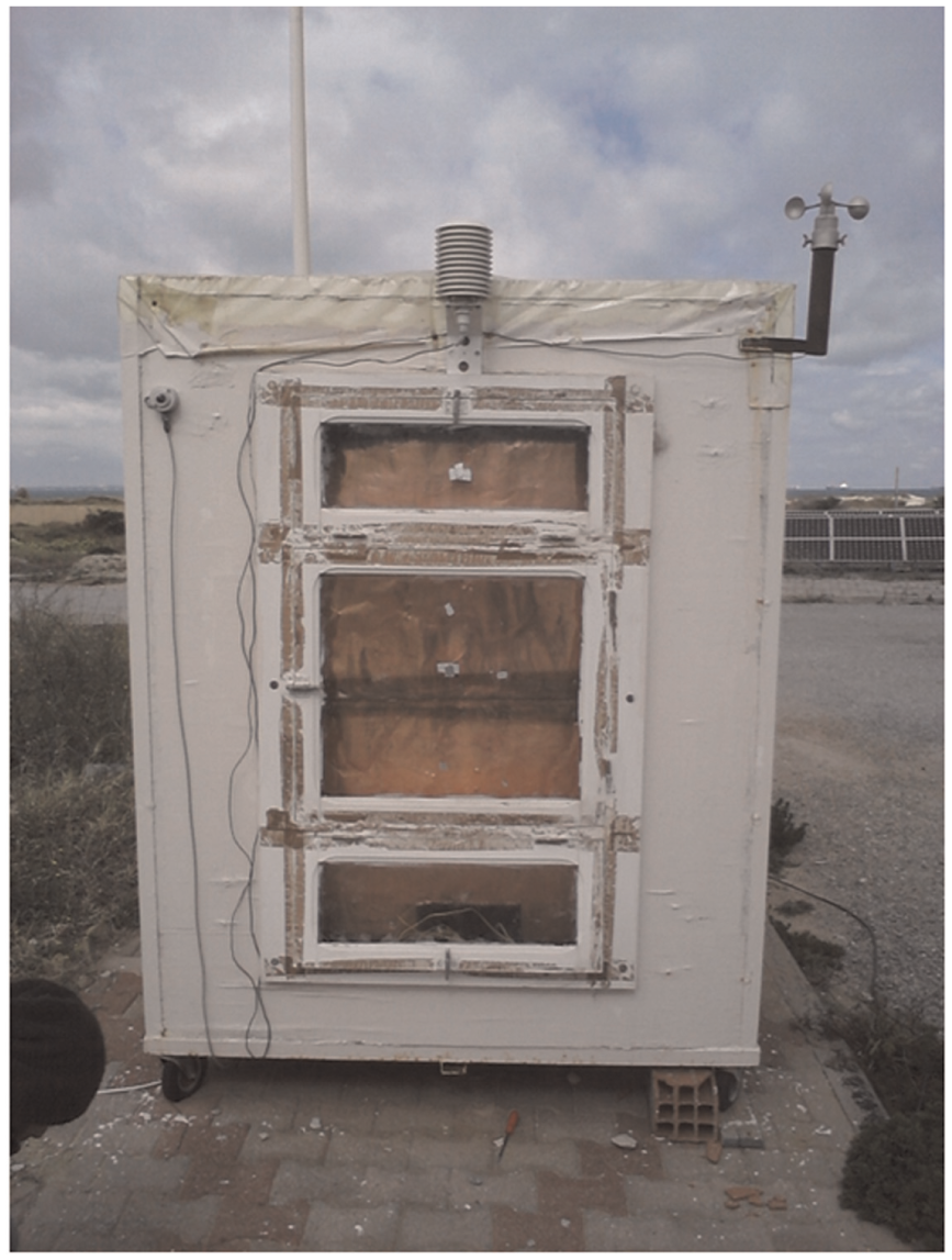
External view of the test room with the improved Trombe wall without paint.
Material properties.
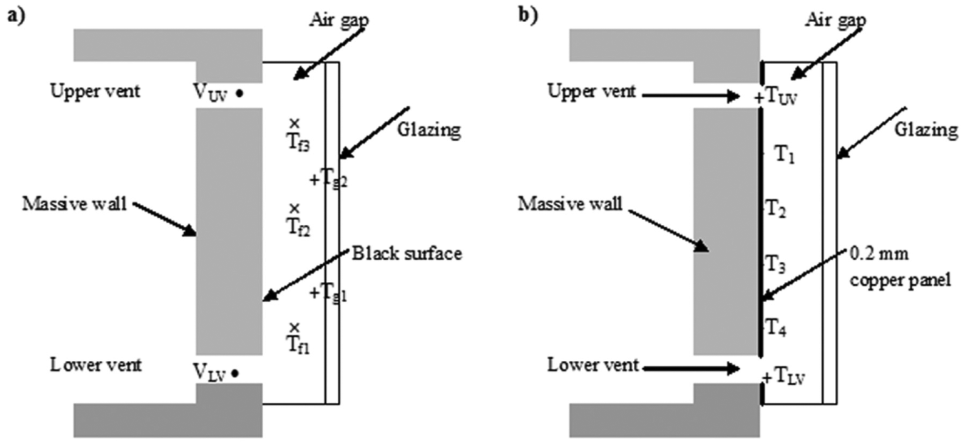
(a) Classical Trombe wall and (b) improved Trombe wall.
Experimental procedure
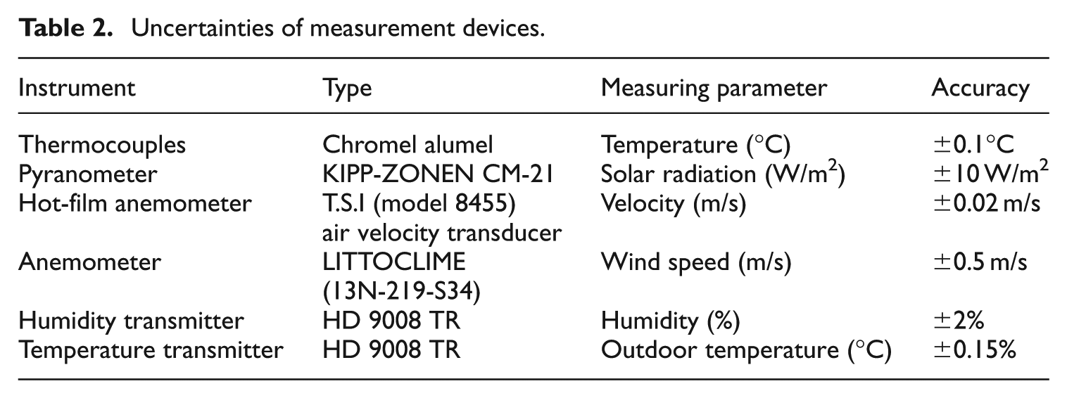
Series of measurements were carried out with the classical and the improved Trombe walls under Tunisian weather conditions for winter heating. To measure temperature, chromel alumel thermocouples were positioned along the storing wall vertically and horizontally, three points along and in the middle of the air gap and two points on the glazing as shown in Figures 2 and 3. Silver paper was used to prevent direct sunshine projecting all probes. The air velocities of the vents were measured using a hot-film anemometer T.S.I model 8455 air velocity transducer located at the center of each vent. To survey and treat the influence of the environmental conditions, a small meteorological station was installed near the test room (Figure 3) and allows the measurement of different parameters (solar radiation, ambient temperature, relative humidity, and wind speed). The outdoor air temperature and the relative humidity were measured using the temperature and humidity transmitters (HD 9008 TR). The wind speed was measured by an anemometer (13N-219-S34). Global solar radiation intensity was recorded with the KIPP-ZONEN CM-21 Pyranometer. All instruments and probes were connected to the Agilent (HP34970A) data acquisition system, and the data were collected every 5 min and then saved in the computer with a data-logger device. Table 2 sets the accuracy of all measurement instruments.
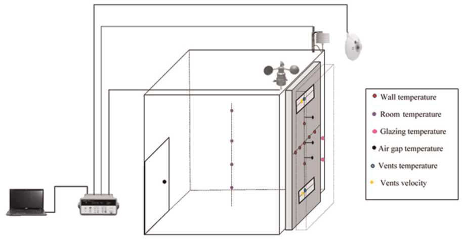
Schematic plan of the experimental setup.
Uncertainties of measurement devices.
Results and discussions
Climatic conditions
In order to compare the classical and the improved Trombe walls under the same climatic conditions, we have chosen two typical days in the same month since the amount of incident solar radiation on the wall does not change significantly in 1 month. Among the recorded data, we choose the sunniest days for the studied systems corresponding to 10 January 2012 for the classical wall and 30 January 2012 for the improved one. These two days have been selected from measurements because the outdoor air temperatures are similar. The hourly ambient conditions, which are the global solar radiation on the south façade of the test room and the outdoor air temperature change during 10 January 2012 and 30 January 2012, are sketched in Figures 4 and 5.
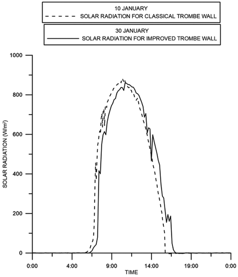
Evolution of solar radiation for Trombe walls.
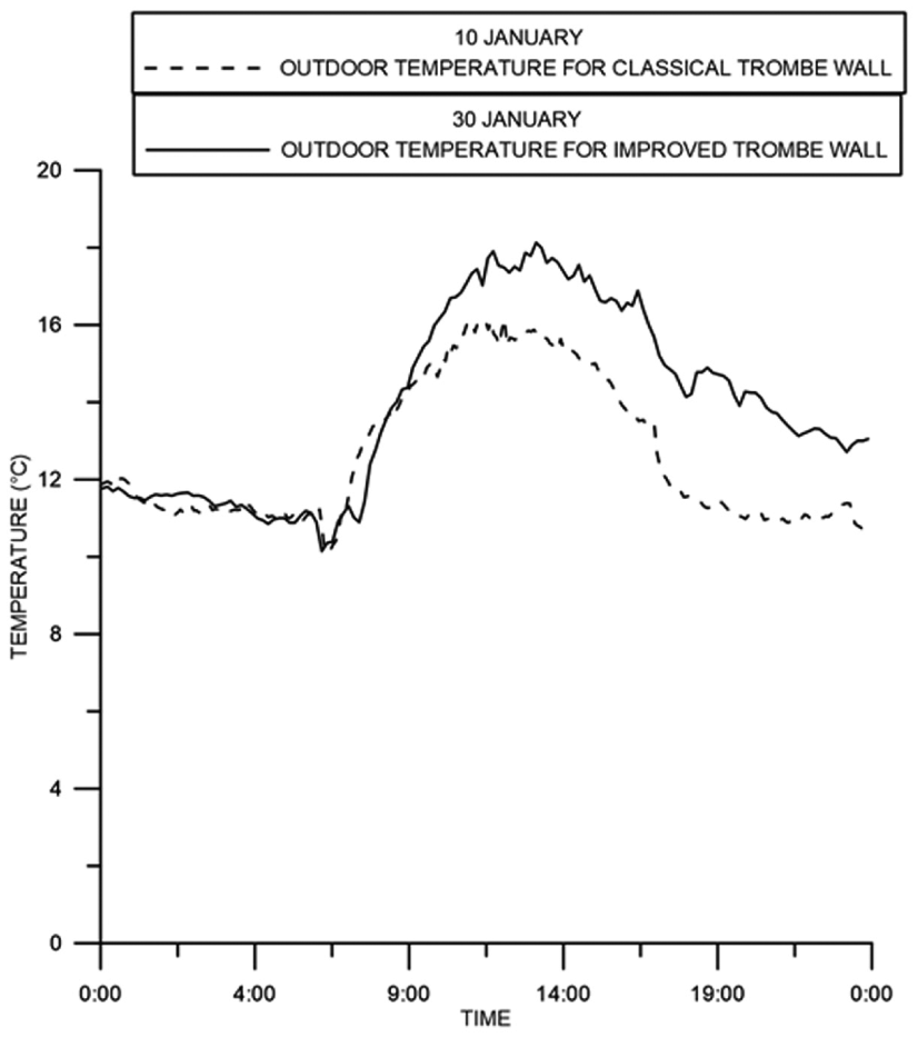
Evolution of outdoor temperature for Trombe walls.
As shown in Figure 4, the global solar radiation on the vertical surface of the two walls reaches the maximum values of the day at about 11:00, which are, respectively, 883.49 W/m2 at 10:53 for the classical case and 861.47 W/m2 at 11:12 for the improved Trombe wall. Figure 5 reveals that outdoor air temperature values are similar at the beginning of the day, and then only a difference of 2°C is observed between maximums. For the classical case, a maximum value of 16.16°C at 12:33 and 18.12°C at 13:32 for the improved case is reached. As we noted, the solar radiation is abundant and can be useful for free heating.
Climatic factors analysis affecting Trombe wall operating
The performance of the improved Trombe wall is mainly affected by the climatic factors such as outdoor temperature and incident solar radiation. For this reason, we studied the following different climatic cases:
Low outdoor temperature with low solar radiation;
High outdoor temperature with high solar radiation;
Low outdoor temperature with high solar radiation.
For each case, individual days are picked from the measurement and the influence on test room temperature was examined.
Low outdoor temperature with low solar radiation
In this case, there are no direct gains during the operation period of the solar wall, which mainly affects its performance. Figure 6 represents the evolution of solar radiation, outdoor temperature, and the temperature inside the test room on 1 January. It is a cloudy and a cold day with a maximum of outdoor temperature reaching 16.33°C at 14:52. The test room temperature increases progressively under the influence of diffuse solar gains and reaches a maximum of 16.58°C. It can be clearly seen that the difference between the two temperatures always remains small during the solar wall operation, due to the absence of direct solar gain effects. Additionally, at 16:52, the influence of diffuse solar gains is completely hidden and the test room temperature falls down, as there is no additional heat gain from the sun. As a result, the heating effect of the solar wall on the test room during this day is considerably small. Therefore, the solar radiation is the main parameter for the Trombe wall operation.

Case of low outdoor temperature with low solar radiation.
High or low outdoor temperature with high solar radiation
The second parameter affecting the solar wall operation is the outdoor temperature; hence, we studied the effect of two cases of outdoor air temperature (high or low) on room temperature under high solar radiation. The day 24 December represents the case of high outdoor temperature with high solar radiation (Figure 7). It is a sunny and warm day with maximum values of global solar radiation and outdoor temperature reaching respectively 841.55 W/m2 at 11:34 and 20.03°C at 11:44. These values are considered extremely high in winter. For the second case, we consider the day of 2 December (Figure 8), it is a sunny and cold day and the solar radiation reaches a maximum value of 893.7 W/m2 at 11:07 but the maximum of outdoor temperature does not exceed 16.55°C at 13:17.
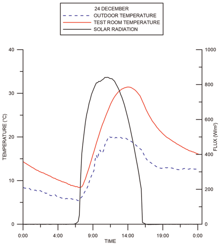
Case of high outdoor temperature with high solar radiation.
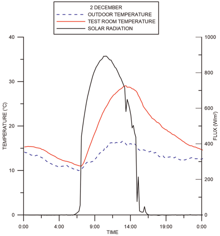
Case of low outdoor temperature with high solar radiation.
From the two graphs, the climatic conditions of these two days contribute to the increase in the test room temperature. During the operation period of the solar wall, the difference between the test room and outdoor temperature is high. In the absence of the sun, the room temperature decreases slowly due to the room insulation and the transfer of stored energy into the room during the late hours of the day. It can be deduced from graphs that the indoor temperatures are closely near with a difference between the two maximums of 2.3°C. High solar gains and average outdoor temperatures are the main climatic conditions that ensure the solar wall performance.
Comparative study between the classical and the improved Trombe walls
Comparison of test room temperature for the two systems
The test room temperature is the main parameter that reflects the functioning of Trombe wall. Figure 9 represents the distribution of the test room temperature during the 24-h operation of the classical and the improved systems; the room is heated by the principle of thermocirculation during the day and by inertia of the wall in the evening. The results obtained show that under ambient conditions, indoor temperatures increased considerably: for the classical Trombe wall, a maximum of 26.35°C is reached at 14:18, and for the improved Trombe wall, a maximum of 29.8°C is reached at 14:22. It can be concluded that the Trombe wall evidently enhances both the test room temperatures, but the indoor temperature is further increased by the improved Trombe wall system. This shows that the copper coating provides a remarkable indoor temperature increase. Observing from the curves, the maximum indoor temperature of the improved Trombe wall system is higher than the temperature of the classical Trombe wall system during the time when there is sunlight. Furthermore, at night, the indoor temperature of the room with the improved Trombe wall is even higher than that of the room with the classical Trombe wall, though it is slightly lower around sunset.
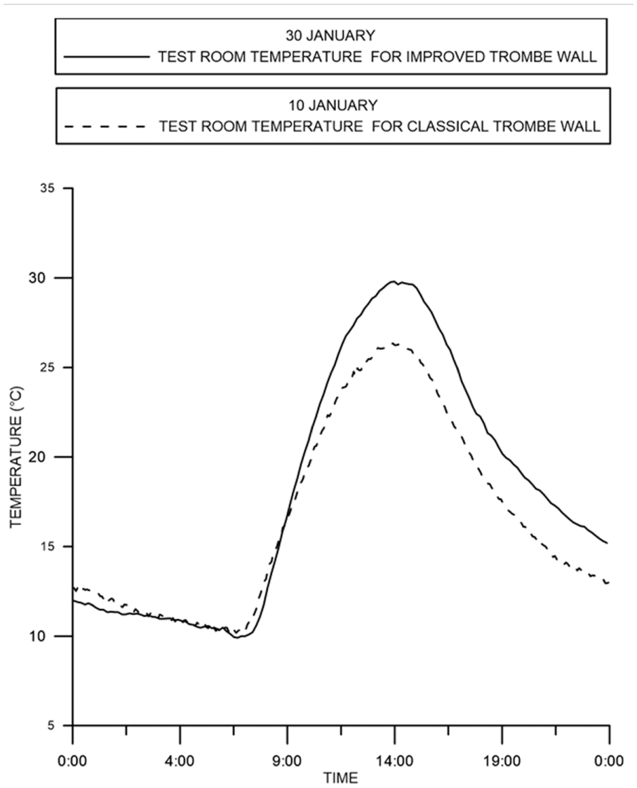
Evolution of test room temperature of the improved and the classical Trombe walls.
Comparison of temperature distribution on the wall
The modified Trombe wall should be able to improve heat absorption for the heating season since the sunrays will directly strike its exterior surface. Preliminary investigations were conducted to determine and compare the wall temperature distribution. The temperature variations of outer surfaces with the improved and the classical Trombe walls are shown in Figure 10. At the sunrise, the wall temperature for the two cases is closer. Then, the temperature of the classical wall reaches its maximum while the improved wall temperature keeps on increasing. During daytime, the increase of the absorber temperature is more notable than that of the classical wall. We can note that the exterior surface temperature of the improved Trombe wall is 5.48°C higher than the case of classical Trombe wall. In order to follow the heating effect, it is essential to study the evolution of temperature on the inner surface of Trombe wall (Figure 11).
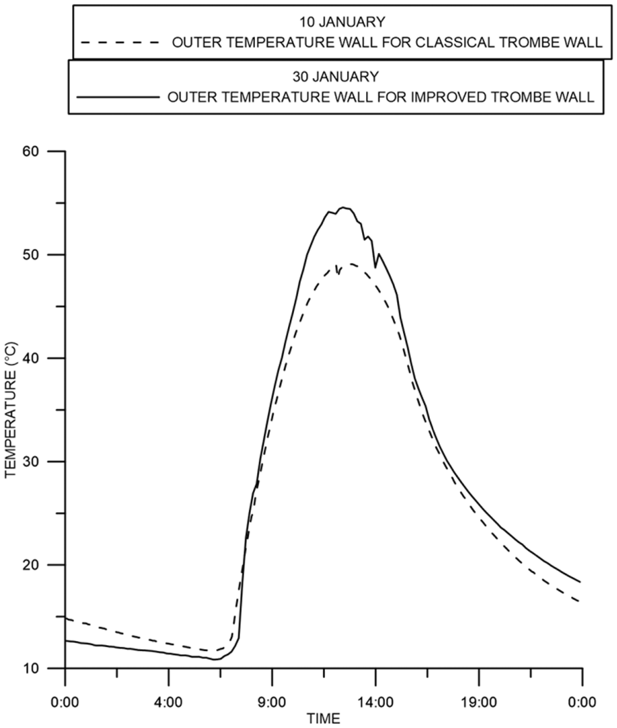
Evolution of outer wall surface temperature of the classical and the improved Trombe walls.
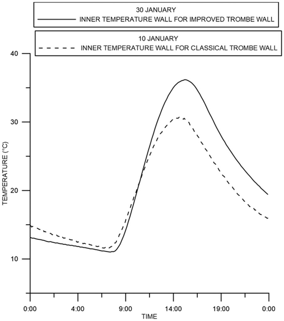
Evolution of inner wall surface temperature of the classical and the improved Trombe walls.
At the start of the day, typically, the inner surface temperature of the Trombe wall falls until solar energy absorbed by the exterior diffuses through the wall. Since the outer surface temperature of the classical wall reaches its maximum, the heat reaches the inner wall surface of the classical system before the improved one. However, the inner surface of the improved Trombe wall is about 5.47°C higher than the classical case, which reveals the enhancement of the thermal transfer by conduction through the wall. It is clear that the wall starts collecting energy during the day and then restores it during the nighttime.
Comparison of temperature distribution in the air gap
The efficiency of a solar wall mainly depends on the quality of absorption and heat exchange between the massive wall and the air. Figure 12 shows comparatively the air gap temperatures for the two types of walls. The experimental results infer that all the day, the air gap temperature of the improved wall is higher than the classical Trombe wall. We remark a significant temperature variation in the air gap because of the increase in the outer surface wall temperature of the improved Trombe wall and the further heating of the wall surface (copper panel). Consequently, the air, in contact of the outer surface of the wall, goes up along the hot wall and transfers more heat into the room through the upper vent, which indicates that higher heat conductor values can significantly improve heat absorption and transfer across the air gap of the Trombe wall.
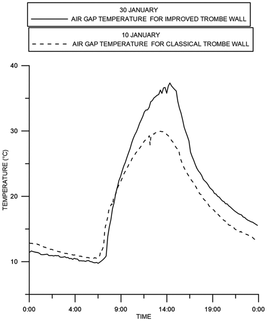
Evolution of air gap temperature of the classical and the improved Trombe walls.
During night, when the outdoor temperature drops, the temperature in the air gap decreases; therefore, it is important to analyze the effect of the glazing cooling on the thermal behavior of the whole system. Hence, we clustered on Figure 13 the evolution of glazing temperature, outdoor temperature, outer and inner wall surface temperatures, air gap temperature, and test room temperature. At about 16:48, when the solar radiation decreases, all temperatures present similar trends and they decrease progressively, the outside temperature and the glazing temperature get closer producing the cooling effect of the glazing. In addition, the examination of Figure 13 shows that the temperature of outer wall surface and the air gap temperature are always much higher than the glazing temperature. The temperature of the test room is closer to the air gap temperature. This fact is explained by the escape of warm air from the room to the air gap through the upper vent, which pushes the cooler air in the air gap into the room through the lower vent. Consequently, the heat may be lost from the indoor to the exterior by the Trombe wall. To prevent such reverse circulation, simple openable dampers need to be provided on the upper vents.
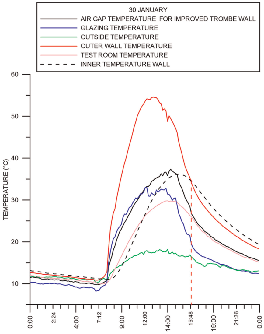
Evolution of glazing temperature, outdoor temperature, outer and inner wall surface temperatures, air gap temperature, and test room temperature.
Comparison of temperature and velocity distribution of the wall vents
The vents facilitate the transfer of the collected heat by free convection (thermocirculation) from the air gap to the interior of the test room. Comparative testing of both massive walls included measuring of distinctive temperatures at walls vents. With regard to Figure 14, temperature variations are sensitive to the solar radiation evolution, they increase toward their maximum value and decrease according to the fall of solar flux. The vent air temperatures of the improved system are higher than the vent temperature of the classical system. Nevertheless, the difference in temperature between the entry and the exit of the wall is about 6.64°C for the classical system opposing to 8.5°C for the improved wall. The upper vent temperature for the improved wall is expected to remain higher at night than in the classical case, therefore reducing the night heat losses. As excepted, since the temperature at the upper vent increases in the improved Trombe wall, the velocity at the upper vent also increases, therefore causing the amelioration of the airflow rate reaching the interior of the test room by thermocirculation (Figure 15). We recorded a mean of 0.42 m/s with the improved Trombe wall against a mean of 0.3 m/s for the classical case.
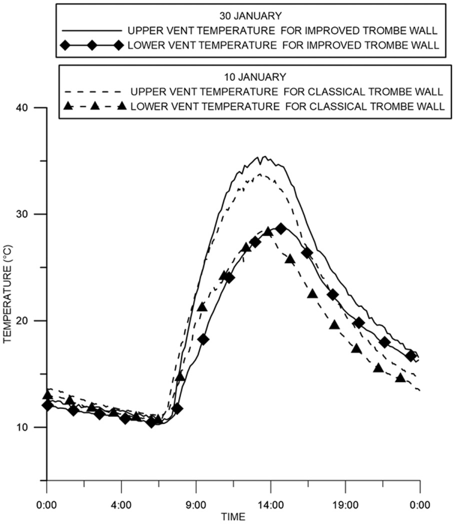
Evolution of vent air temperature of the classical and the improved Trombe walls.
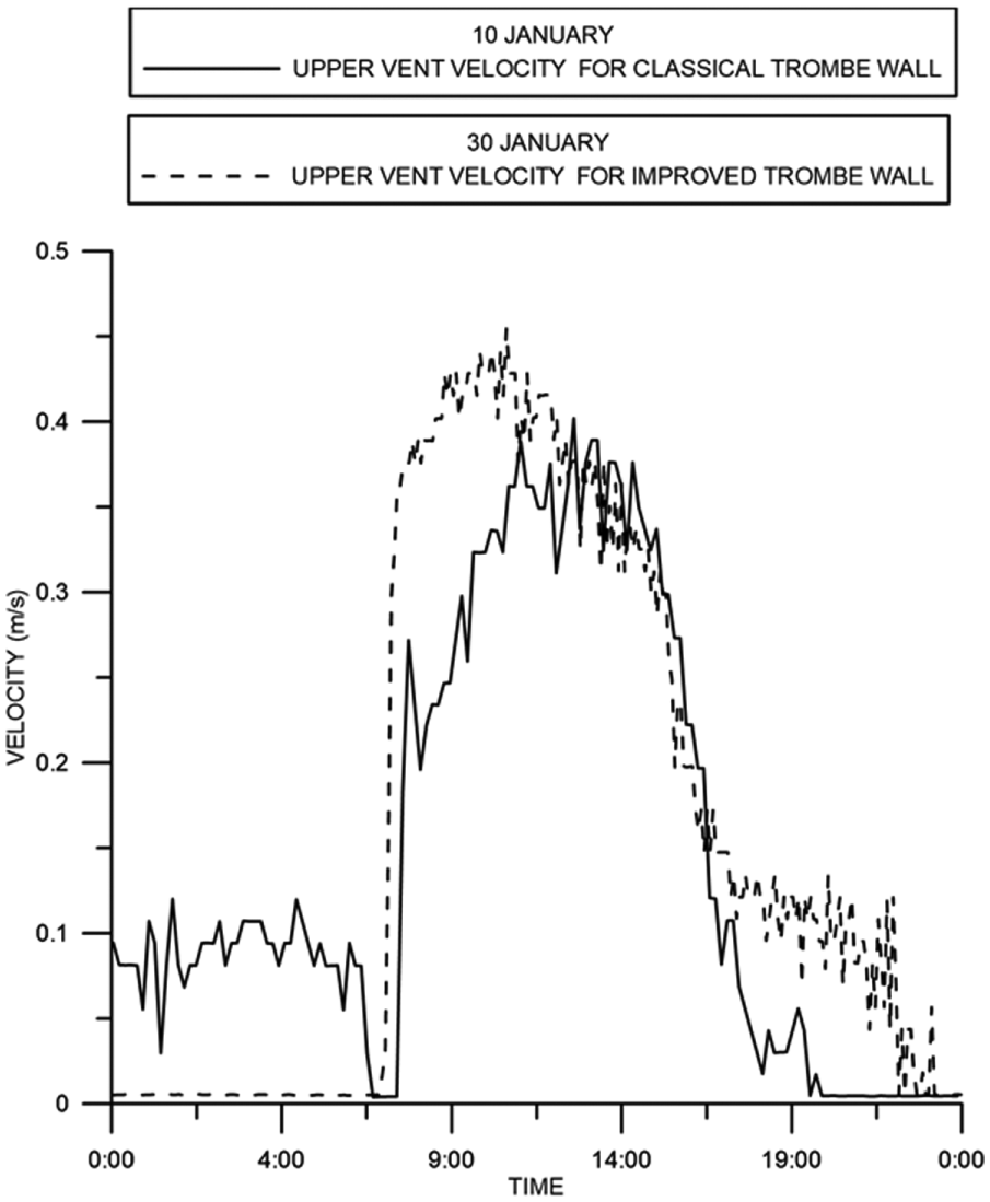
Evolution of upper vent air velocity of the classical and the improved Trombe walls.
Comparison of wall performance
In order to evaluate the performance of the solar wall, it is important to quantify the heat gain delivered by the wall through the estimation of conductive and convective fluxes.
Conductive flux
Heat transfer by conduction through the wall depends on the wall size and its composition, a thermal delay appears between heat absorption and diffusion of heat inside the test room. Heat storage is an important factor for extending the duration of free heating to the sunset periods.
The conductive heat flux qcond is calculated from the following equation
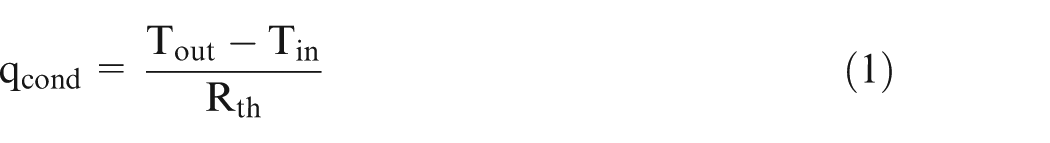
where qcond is the conductive heat flux from outer to inner surface of the wall; Tin is the inside surface temperature; Tout is the temperature of the outside of the wall; and Rth is the thermal resistance, and it measures the ability to retard heat flow in wall thickness and it was calculated as a resistance of a composite wall. It includes the thermal conductivity of the wall thickness
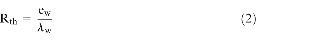
Figure 16 shows the variation of the conductive heat flux through the Trombe wall. The conduction of heat into the building through the wall is directly proportional to the wall temperature difference between the outside and the inside surfaces.
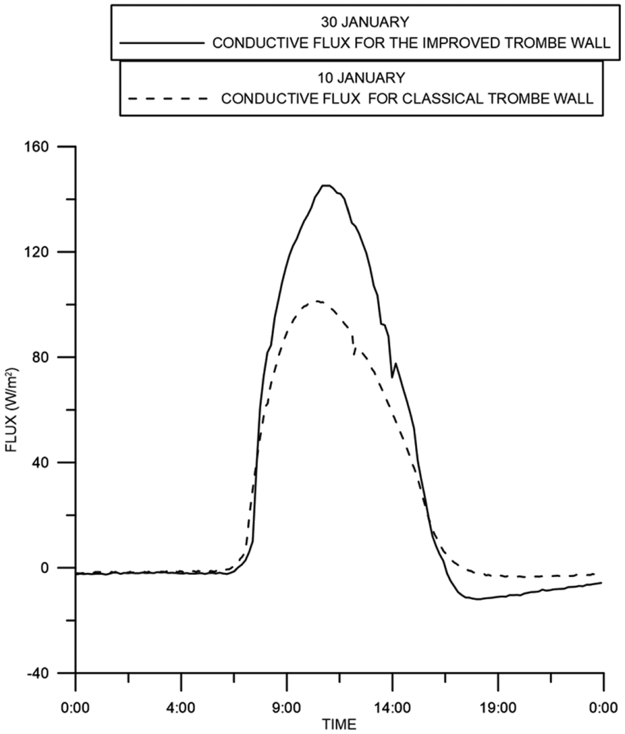
Evolution of conductive flux of the classical and the improved Trombe walls.
Indeed, the maximization of the amount of absorbed radiation by the external surface of the improved wall has increased the outside surface temperature and therefore the conducted heat.
The maximum conductive flux for the improved wall was 145.19 W/m2, while for the classical wall it was about 101.3 W/m2, which reveals that the conduction through the Trombe wall has significantly improved.
Convective flux
Unlike the conduction process, the convection is stopped during solar radiation outage; thus, Figure 17 shows the evolution of hourly convective flux during the operating period of the classical and improved walls. Aimed at the acceleration of thermocirculation phenomenon, the idea is based on the application of a copper panel over the outer wall surface. The air entering through the lower vent is over heated in contact with the external wall surface, rises and circulates toward the air gap to the room through the upper vent. As shown in Figure 17, the convective flux to the room is improved and the variations are observed faster than the classical wall.
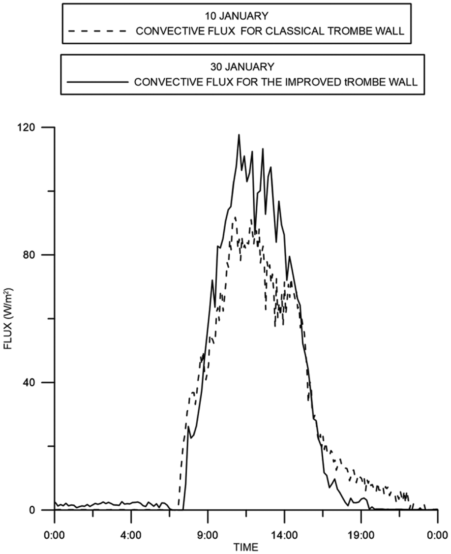
Hourly variation of convective flux.
qconv is the convection heat flux to room air from the element surface
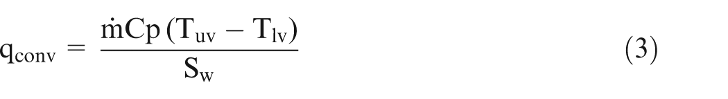

where Tuv and Tlv are, respectively, the temperatures at the upper vent and the lower vent.
In fact, the mean maximum convective flux in the classical case is only about 85.51 W/m2, and for the improved system, this value is about 104.73 W/m2.
Uncertainty analysis
Since this study is mainly based on experimental results, an uncertain analysis was carried out on the calculated parameters using the propagation of error method (Garmash, 2003). It is a derived calculation designed to combine uncertainties from multiple measured variables given in Table 2. Uncertainty for heat flux was calculated for various tests. For the conductive heat flux, the uncertainty goes from 0.51% to 0.58%. The relative uncertainty of mass flow ranged from 0.49% to 0.514%. For convective heat flux, the relative error is found between 5.4% and 5.8%.
Performance evaluation
For the space heating, the effectiveness of the Trombe wall is evaluated by the heat introduced into the room from the Trombe wall. Therefore, the convective and conductive heat to the room stands for the effectiveness of the solar heating from the wall. Then, the thermal efficiency of the wall is given by
The solar heat gains available from the Trombe wall comprises the solar heat transferred into the room by conduction through the wall and natural convection by airflow from the upper vent.
Figure 18 shows the comparison of the efficiency evolution for the classical and the improved Trombe walls. For the two cases, the efficiency depends strongly on the solar radiation values. According to the experimental data, at the sunrise, the hourly efficiency increases proportionally to the incident solar radiation and drops to its lowest value at the end of the day. The efficiency reaches a mean maximum of 0.671 for the improved wall, while the classical wall efficiency reaches a mean of 0.441, which represents a good performance. In fact, the wall produces heat during the day as long as the solar radiation arrives onto it. When the solar radiation decreases, the thermal efficiency is maintained constant. This is due to the start of the conduction process through the wall. The Trombe wall dissipates the heat that it gained during the absorption–storing process. This dissipation is gradual after sunset and depends on the thermophysical properties of the wall. In addition to the quoted observations, other interesting features may be noted in Figure 18. Indeed, the thermal response of the improved wall is higher than the classical wall. Heat is transferred by two ways: convection due to the outer overheated wall surface and conduction to the room even after sunset. However, copper sheet provides higher solar radiation gain for the thermal wall during daytime, which enhances the thermal transfer.
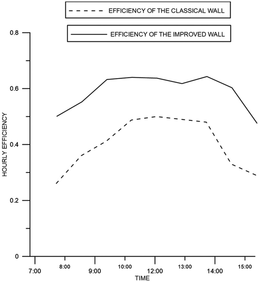
Evolution of hourly efficiency of the improved and the classical Trombe walls.
Conclusion
In this article, an experimental study has been carried out to investigate and to compare the performance of a classical and an improved Trombe wall in Borj Cedria. For the improved case, the absorber wall was reconstructed as a thin black copper panel backed in front of the massive wall, aiming at improving heat absorption and transfer across the wall. The experimental results enable us to draw the following conclusions:
The indoor temperature can be enhanced by the improved Trombe wall system compared to the classical Trombe wall system.
For a Trombe wall, the important parameters affecting the performance are as follows: the outer wall surface temperature, the air gap temperature, and the velocity and the temperature at the vents.
The improved Trombe wall design gives an increase for both conductive and convective flux.
The south façade design influences the thermal efficiency of the Trombe wall notably from the experimental results, which indicates that the external coating can significantly improve heat absorption and transfer across a Trombe wall.
The gains of the improved case considered could be sustained by further insulation measures during nocturnal period to avoid undesired heat loss from the wall to the surrounding; this will ensure that the interior wall temperature will not reduce considerably, therefore impelling a high start value for the following day. We have shown that applying an exterior coating with high thermal conductivity can considerably improve heat delivery to the Trombe wall.
Footnotes
Appendix 1
Declaration of Conflicting Interests
The author(s) declared no potential conflicts of interest with respect to the research, authorship, and/or publication of this article.
Funding
The author(s) received no financial support for the research, authorship, and/or publication of this article.