






Abstract
Injector elements are an elemental sub-component of any liquid rocket engine, as they are critical in influencing engine efficiency and combustion stability. Therefore, characterizing such elements is of great importance. In regeneratively cooled rocket engines, significant changes in fuel injection temperature can occur between load points or during the development phase. The impact of such changes on combustion dynamics, however, is not fully understood, especially for swirl injectors. Therefore, this study presents results from a single swirl coaxial injector element hot-fire test campaign where fuel injection temperature is varied between 175 K and 240 K. The injector element injects liquid oxygen and natural gas into an optically accessible combustion chamber at pressures between 35 and 80 bar. It is observed that under high-pressure, low-fuel-temperature conditions, high-frequency chamber modes with frequencies above 15 kHz are increasingly excited. Additionally, high-amplitude oscillations occur for these modes, with peak-to-peak oscillations approaching 20% of chamber pressure. Analysis concludes that, for low fuel injection momentum scenarios, the liquid oxygen injectors couple with the first radial combustion chamber mode, while an additional coupling effect with the fuel injector leads to these high-amplitude instabilities. Combined with the outward flame pulsation observed in the optical data, a mechanism explaining the flame-acoustic interaction for a swirl coaxial injector is proposed. The article concludes by defining stability boundaries for common injection parameters, including velocity and momentum flux ratio.
Keywords
Introduction
Against the background of the growing European launcher and space transportation sector, the fast and low-risk development of cryogenic liquid rocket engines becomes more and more significant. Cryogenic rocket engines offer increased performance and adaptability1,2 as well as operation with non-toxic propellant combinations. An example for such a propellant combination is liquid oxygen (LOX) and methane or the related and mostly similar natural gas (NG). This combination is a popular choice for new engine developments due to its positioning between good performance and easier handling compared to other propellants. A critical component of any liquid rocket engine is its injector, as its design can be seen as one of the most dominant factors in determining important engine characteristics such as combustion efficiency and stability. Liquid centered swirl coaxial injector elements are a suitable choice when designing such engines as they generally exhibit very good propellant atomization and combustion efficiency characteristics while also showing good stability and throttle-ability.3,4
Liquid-centered swirl coaxial injector generate a swirling LOX in a central injector post. This swirling flow is often produced by tangential entry ports into the injector post. As a result from the emerging centrifugal forces, LOX is forced to the inner post wall, where it forms a thin liquid sheet. This sheet, no longer confined by the walls when exiting the LOX post, produces a hollow-cone like structure. Low-density fuel, after being heated up by the main combustion chamber’s regenerative cooling circuit, is injected co-axially around the circumference of the LOX post, thus impinging onto the outside of the thin-walled hollow LOX cone leading to a rapid and efficient atomization. This fuel to LOX impingement, shearing and general interaction process contributes significantly to the working principle of such an element. Analog to shear coaxial injectors, two non-dimensional parameters commonly used for evaluating the magnitude of these interaction forces are the fuel-to-oxidizer velocity ratio



Any swirl coaxial injector element has to be designed with the ability to deliver and promote sufficient LOX/fuel interaction. To design an injector in accordance to that requirement, the upstream propellant states must be known. While this is generally no issue for the LOX, in most methane or NG engine cycles the liquid fuel is used for regeneratively cooling the main combustion chamber before being injected. Depending on the given heat input fuel temperature at the injector can vary greatly. While predictions of fuel injection temperature are obtained as a result from the engine’s system analysis, the actual temperature encountered in testing of the engine might still differ significantly. To safely cope with such differences, an injector element’s behavior in dependence of varying fuel temperature has to be understood. For this purpose, subscale testing and characterization of injector elements should include modifications of the fuel temperature.
During a fuel temperature ramping (FTR) test run with such a swirl injector in the frame of a single-element characterization test campaign, increased pressure fluctuations were observed in the combustion chamber for low fuel injection temperatures.
This article describes the encountered combustion instabilities and assesses the their respective origins and trigger mechanisms. The article is structured as follows. First the used experimental and diagnostics setup is described. Later the results obtained from five conducted test runs are discussed. This discussion starts with a general description of the instabilities and test sequences. Subsequently, the origins of the observed oscillation frequencies are evaluated and linked to different components and sources. After the detailed analysis on the trigger mechanisms of a short-lived HF burst phenomena, the paper concludes with the definition of stability limits for the tested swirl coaxial injector element.
Experimental setup
The experiments presented in this work are conducted at the European research and technology test facility P8 at the German Aerospace Center (DLR) Institute of Space Propulsion in Lampoldshausen, Germany. 8 For this purpose, a single liquid-centered swirl coaxial injector element is designed, manufactured and integrated into the existing optical research combustion chamber model ‘‘N” (BKN). 9 The injector element is adapted for operation with LOX/NG at main-stage engine relevant pressukre and mass flow rate levels. As such, the boundary conditions from the REST HF-10 methane test case 10 are chosen as the injector’s nominal operating load point.
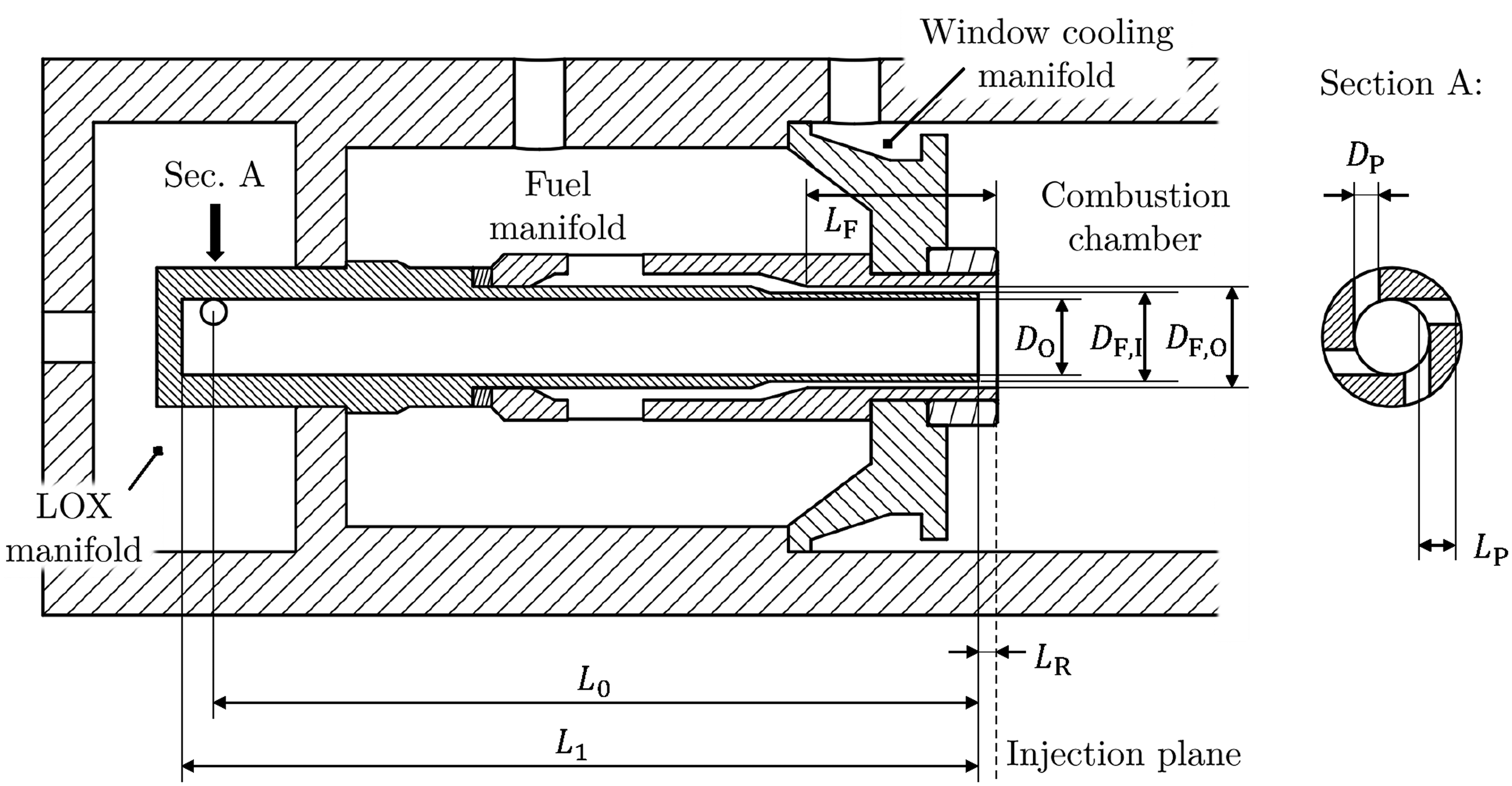
A cross-sectional sketch of the tested single-injector element is shown in Figure 1. The injector element consists of a central LOX post of constant diameter
Single-injector element geometric characteristics.
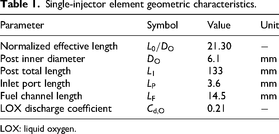
LOX: liquid oxygen.
The combustion chamber itself has a diameter of
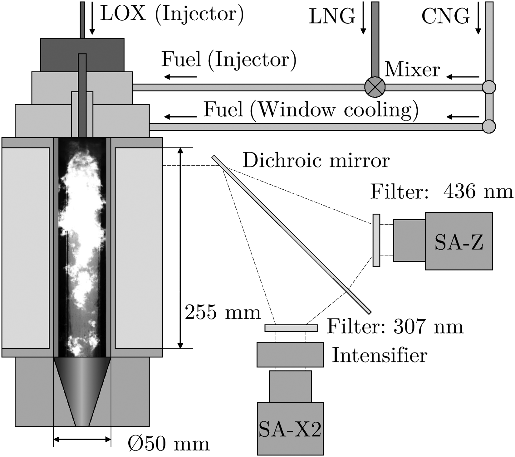
Combustion chamber ‘‘N” and optical diagnostics setup at the P8 test bench (modified from Bee et al. 11 ).
The propellant feed temperatures and pressures inside the injector head are measured with two type K thermocouples and two static pressure sensors for each manifold (LOX and fuel). The film cooling manifold features one type K thermocouple and one static pressure sensor. To capture high-frequency phenomena two flush-mounted unsteady pressure sensors (type Kistler 601CA) are mounted to the LOX dome with an additional one also flush-mounted at the fuel manifold. The chamber segment of BKN is equipped with extensive measurement instrumentation as well. In total,
Static pressure sensors are sampled with a rate of
In the frame of the injector test campaign, an optical diagnostics setup consisting of two high-speed cameras is operated. The first camera (model Photron® Fastcam SA-Z) is, in combination with a
Results
In this section, the experimental and data evaluation results are presented. First this section discusses on the general increase in high-frequency combustion oscillations during the FTR test runs. Later, the trigger mechanisms of more short-lived burst phenomena are evaluated.
Effect of fuel temperature on combustion stability
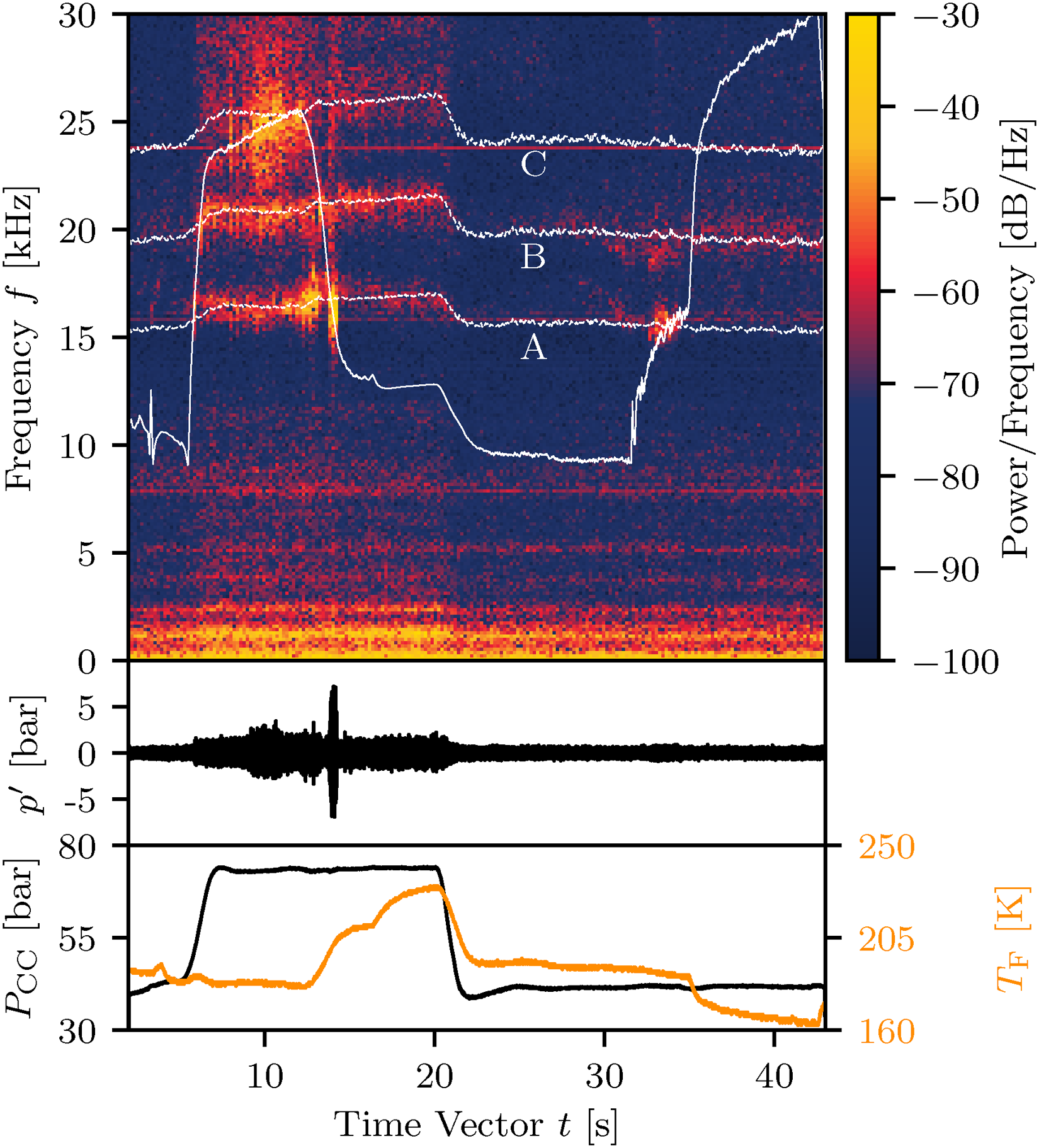
This work focuses on five hot-fire test runs. These runs consist of two nominal fuel temperature runs used as reference test cases (NOM 01 and NOM 02) and three test runs with down-ramping of the fuel injection temperatures (FTR 01–FTR 03). Figure 3 shows the unsteady chamber pressure spectrogram (top), unsteady chamber pressure
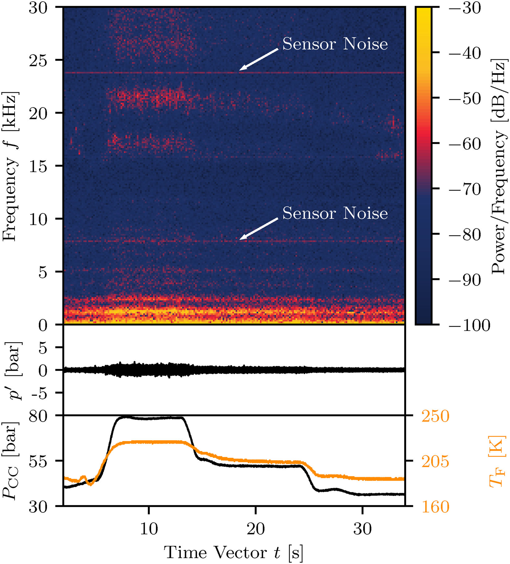
Spectrogram, unsteady pressure signal
The same measurements for an FTR test run are shown in Figure 4. Here, the chamber was operated at two pressure levels (
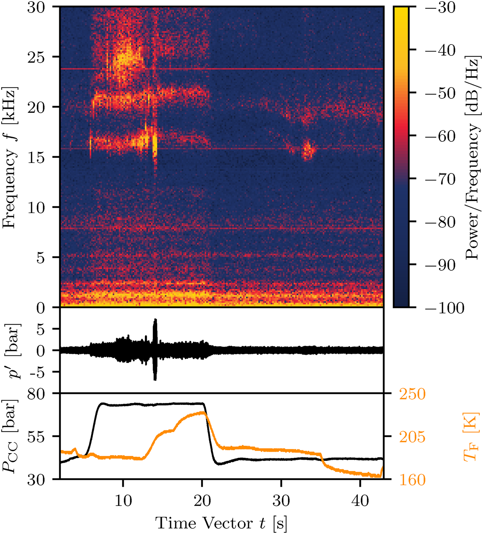
Spectrogram, unsteady pressure signal
As a first part of the analysis of the effects of fuel temperature on the combustion stability, the
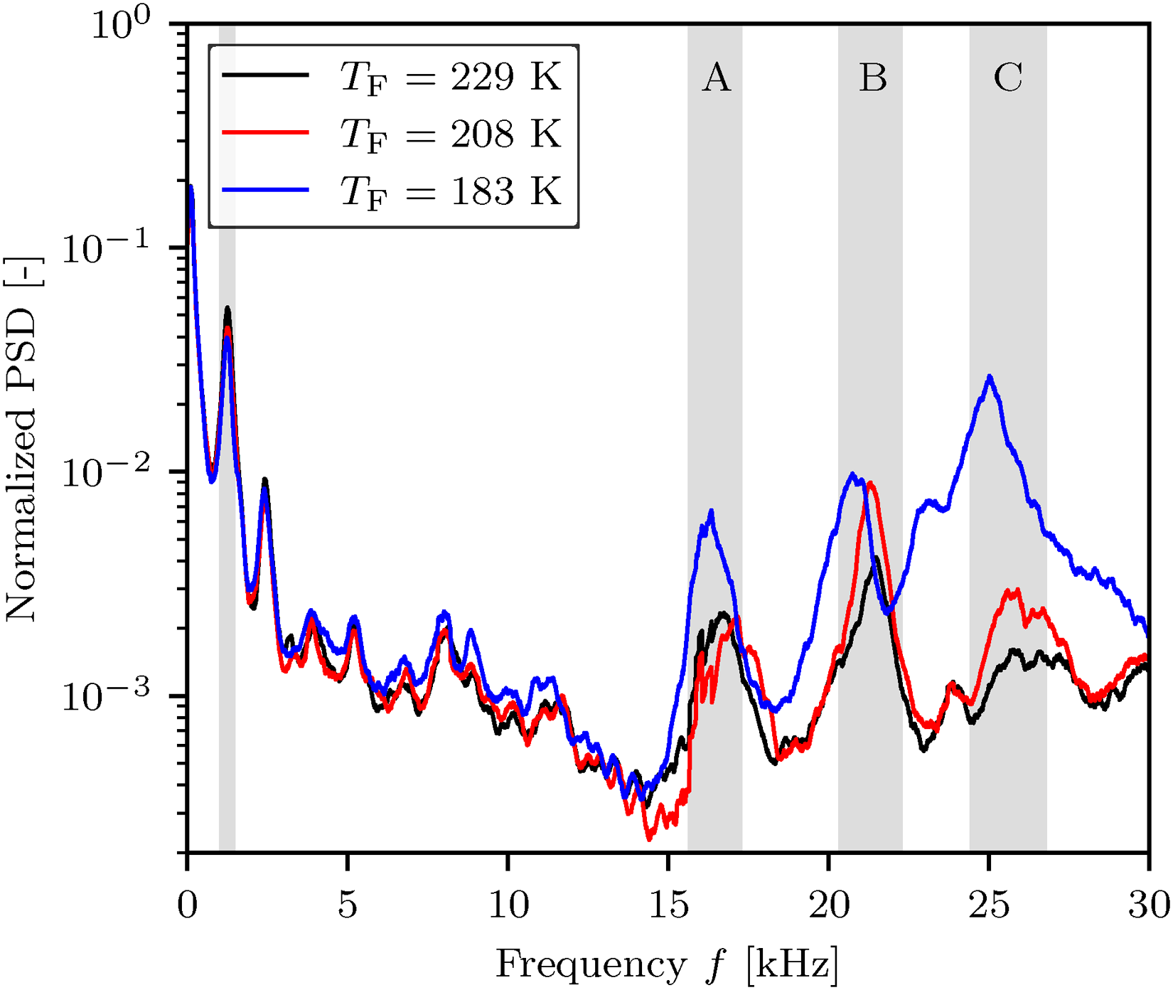
Normalized power spectral density (PSD) of unsteady chamber pressure for different fuel injection temperatures
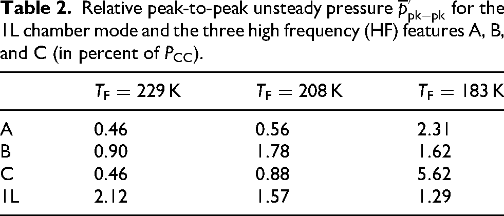
The relative, normalized by the steady-state chamber pressure, peak-to-peak pressure values
In summary, the chamber pressure oscillations for higher fuel temperatures are dominated by the lower frequency L-modes of the combustor, with higher frequency phenomena becoming more pronounced when 
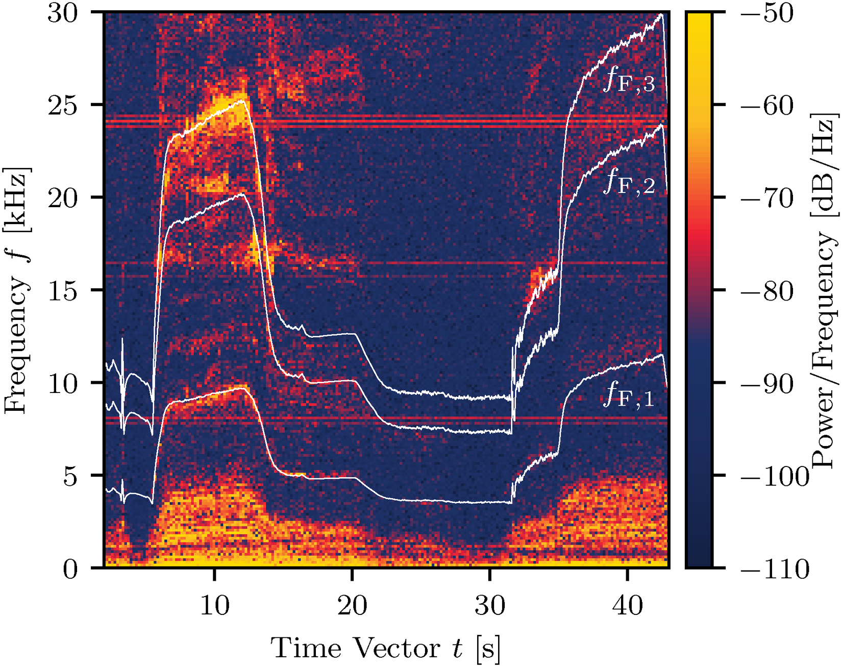
The first six of these calculated modes are annotated as dashed lines in Figure 6, where very good accordance with excited frequency bands is found. A special focus should be set on the 6L LOX post mode, due to it’s apparent vicinity to the feature A visible in the combustion chamber. Further, an excited region can be identified just below the 6L mode (marked by the continuous white line) which follows a similar trajectory—indicating an additional acoustic frequency originating from the LOX injection system. While the exact source of this frequency is not yet completely understood, using a conventional approach
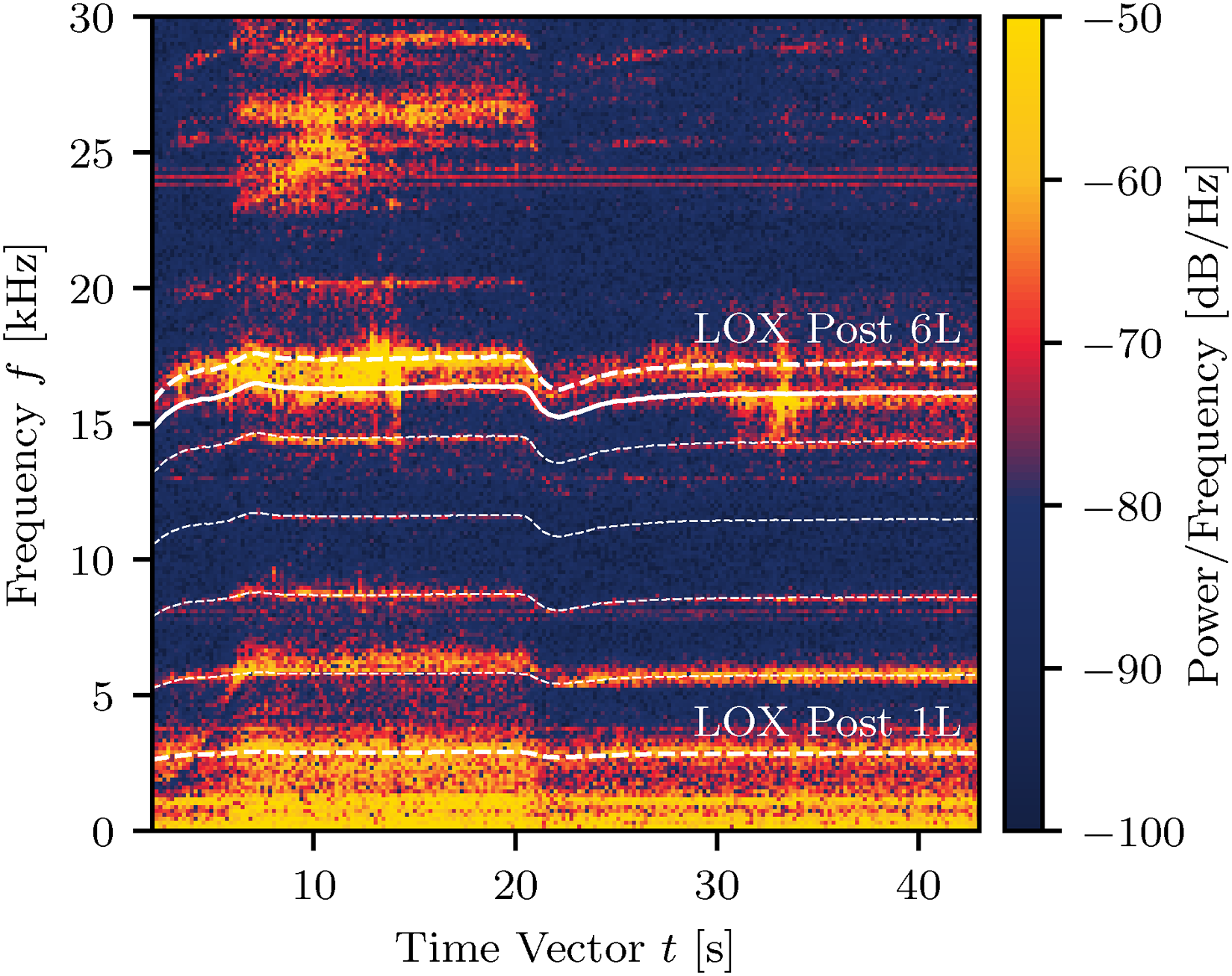
Spectrogram of LOX manifold unsteady pressure with annotated LOX injector acoustic natural frequencies during test run FTR 01. LOX: liquid oxygen; FTR 01: fuel temperature ramping.
Relative peak-to-peak unsteady pressure
Excitation of chamber modes
To identify the instability triggering mechanism, the origin of the features A, B, and C has to be identified. The speed of sound inside the combustion chamber is computed via the NASA Chemical Equilibrium for Applications (CEA) code.
15
By scaling the calculated chamber speed of sound to the observed features A, B, and C with a constant factor, an already promising match can be seen. In Figure 7 those first assumptions are drawn as the gray dashed lines. This is a first indication that these features might indeed be chamber eigenmode frequencies. It is to note that, for now, this indication is based on simple assumptions. To obtain a result with higher precision, a more detailed chamber mode analysis has to be done. The shortcomings of the current approach become apparent by the deviation from the scaled CEA speed of sound estimations to the experimental frequencies later in the run. A reason for the deviations can be, for example, the change of the axial speed of sound profile inside the chamber for different load points and the resulting variable flame morphology. Therefore, a chamber eigenmode analysis using a internally developed low-order tool
16
is conducted. This low order tool uses computational fluid dynamics (CFD) results of the given configuration for the speed of sound profile along the combustion chamber
17
to estimate the necessary correction factors. For the load point
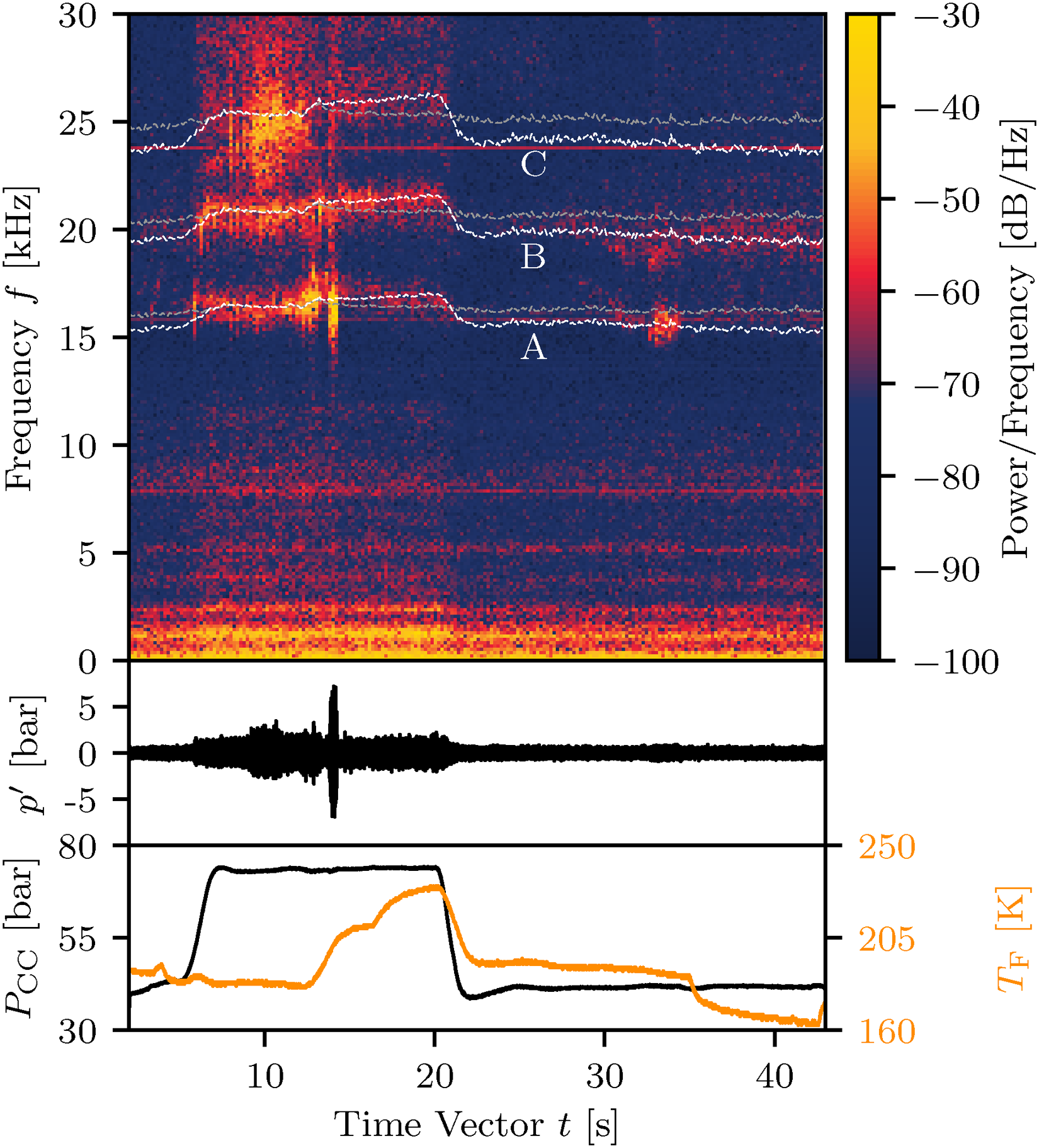
Spectrogram, unsteady pressure signal
Frequencies of main chamber modes predicted by the German Aerospace Center (DLR) low-order tool.
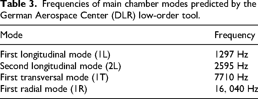
The first two values in Table 3 for the longitudinal modes show a very good agreement with the experiment. The first transversal mode, usually one of the modes of greater interest in LRE combustion chambers, is predicted to be at around
To circumvent this problem, the computed frequencies can be adjusted from the starting load point by defining a correction term. For this, the assumption is made that the heat release, temperature and, therefore, speed of sound distributions inside the near-injector region of the chamber are mostly influenced by the injector’s atomization and flame anchoring behavior. For such injector elements, these parameters are usually considered to be mainly dependent of propellant injection velocity or momentum ratios which, in turn, are mostly defined by 
LOX side injector coupling
Could the observed rise in combustion roughness (broadband chamber pressure oscillations) and the increased excitation of the higher frequency chamber modes be simply a result of low
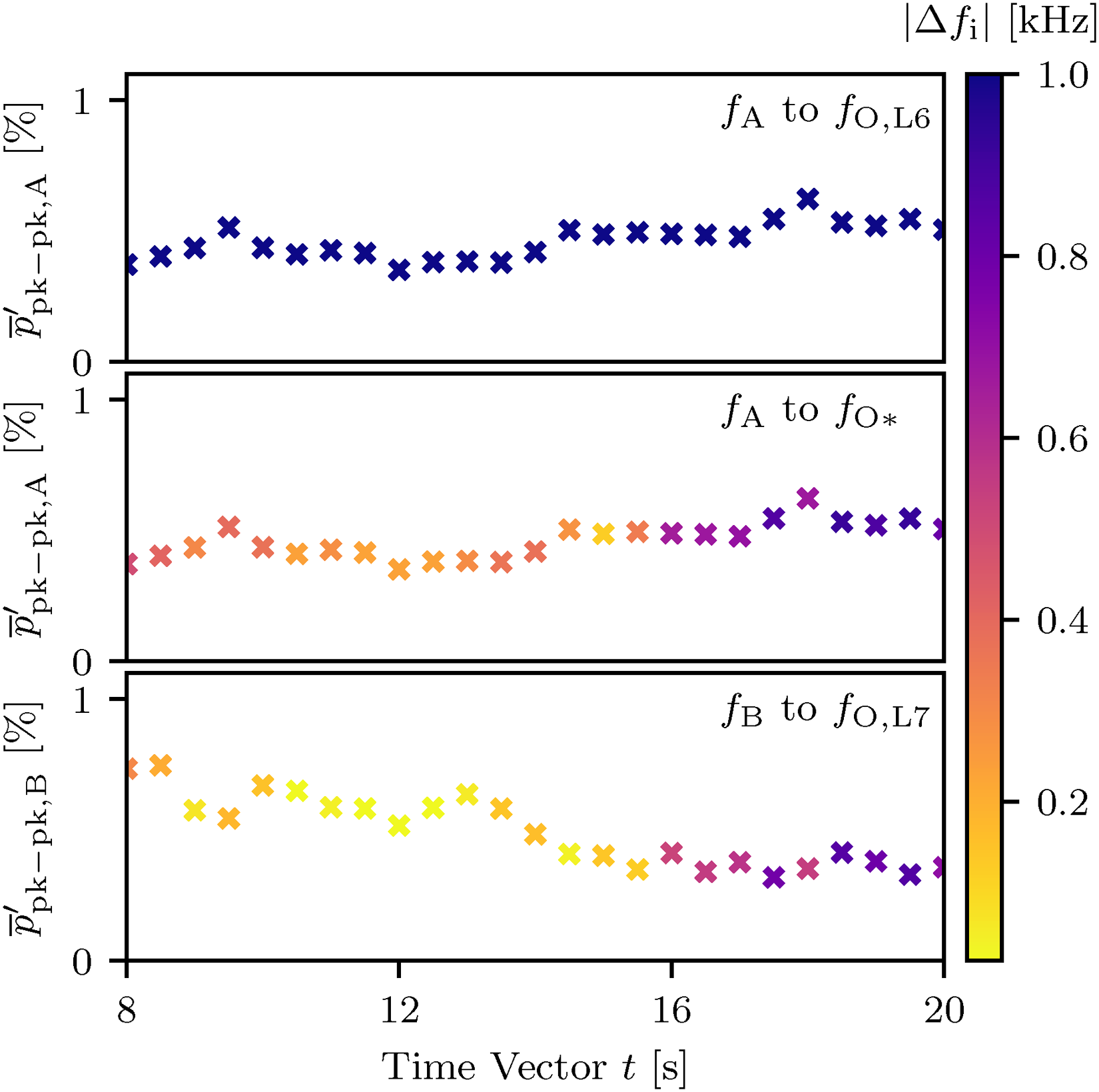
Time evolution of relative chamber mode oscillations
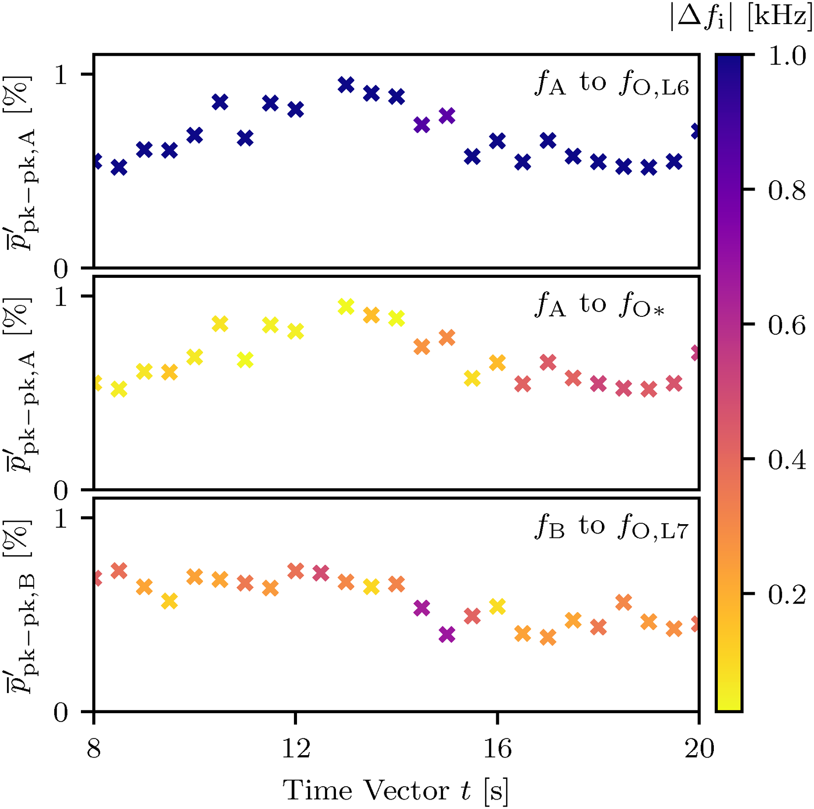
Time evolution of relative chamber mode oscillations
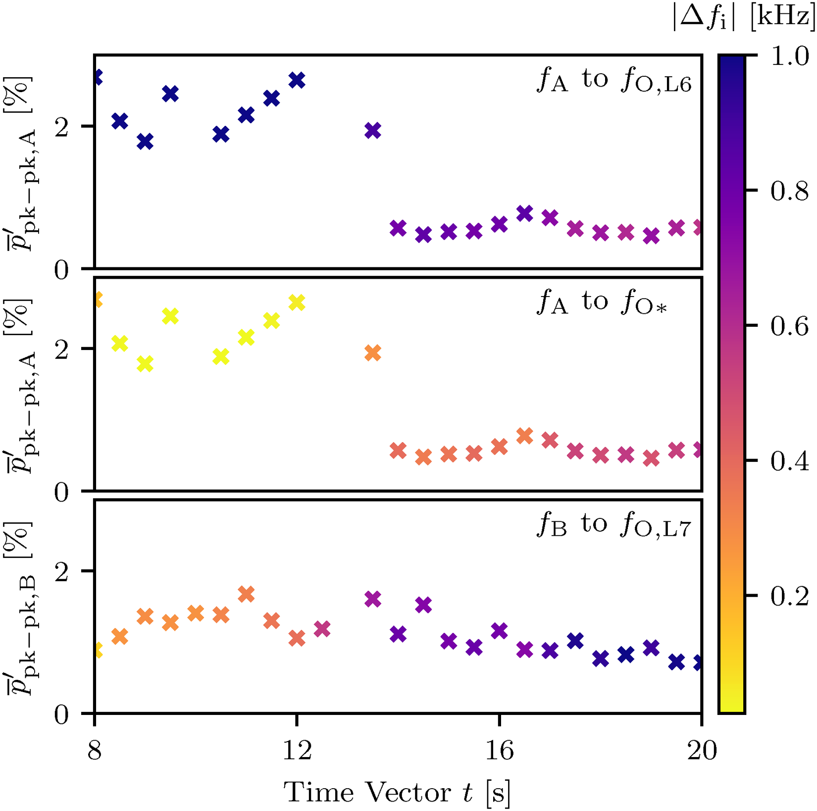
Time evolution of relative chamber mode oscillations
Starting with Figure 8, one can recognize an increased excitation for chamber mode B when the gap to the seventh eigenmode of the LOX injector
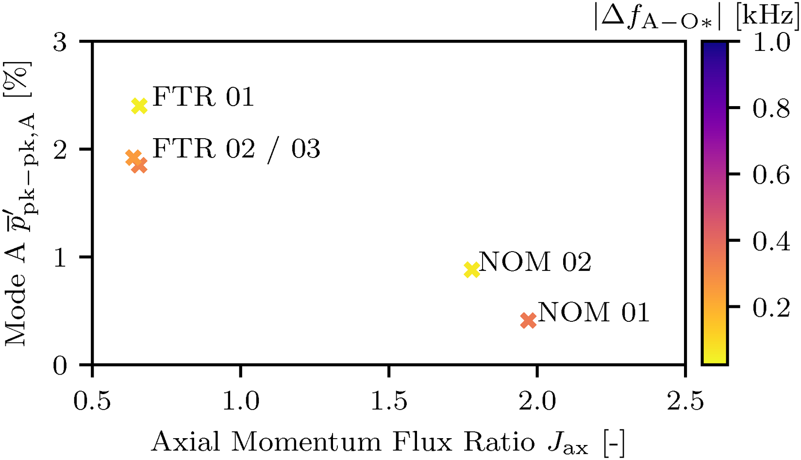
Relative chamber mode A oscillations
Investigation of high-frequency burst phenomenon
The increase in overall combustion roughness for frequencies >
Spectrogram of fuel manifold unsteady pressure with annotated acoustic frequencies of interest
Fuel side injector coupling
In Figure 12, three obvious frequency bands (
During the rapid change in
Spectrogram, unsteady pressure signal
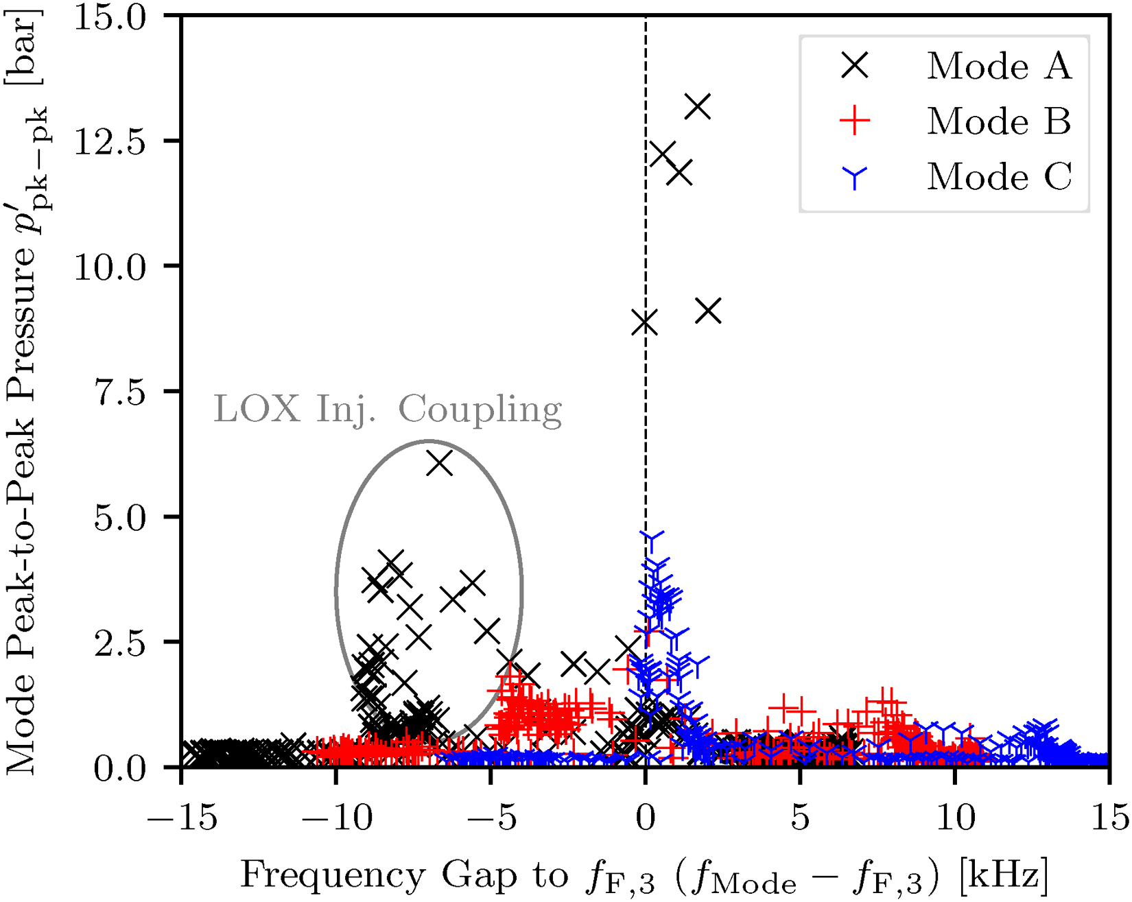
Peak-to-peak values of unsteady chamber pressure
To further investigate the origin of the frequency bands observed in the fuel dome, an acoustic simulation of the entire fuel injector and its manifold is performed in COMSOL multiphysics. The three-dimensional speed of sound distribution inside computational domain is obtained from previous numerical calculations.
17
The domain also encompasses the first
Figure 15 shows the unsteady pressure fields for two prominent frequencies. The first pressure field at a frequency of
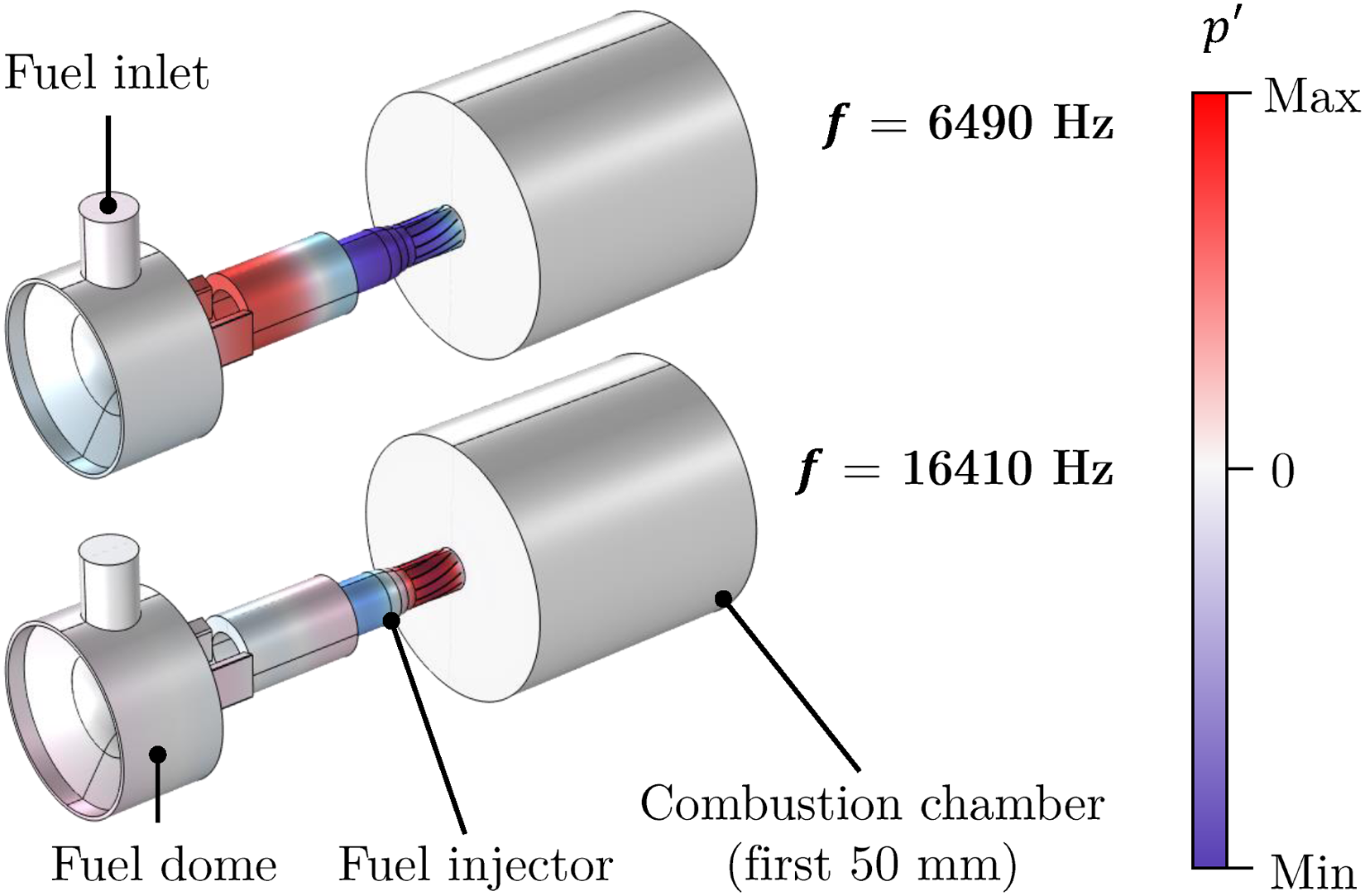
Pressure fields for two prominent frequencies obtained from acoustic simulations of the fuel injector in COMSOL.
Effect of momentum flux ratio
A parameter so far not considered in the analysis of the HF burst phenomenon is the injector mixture ratio
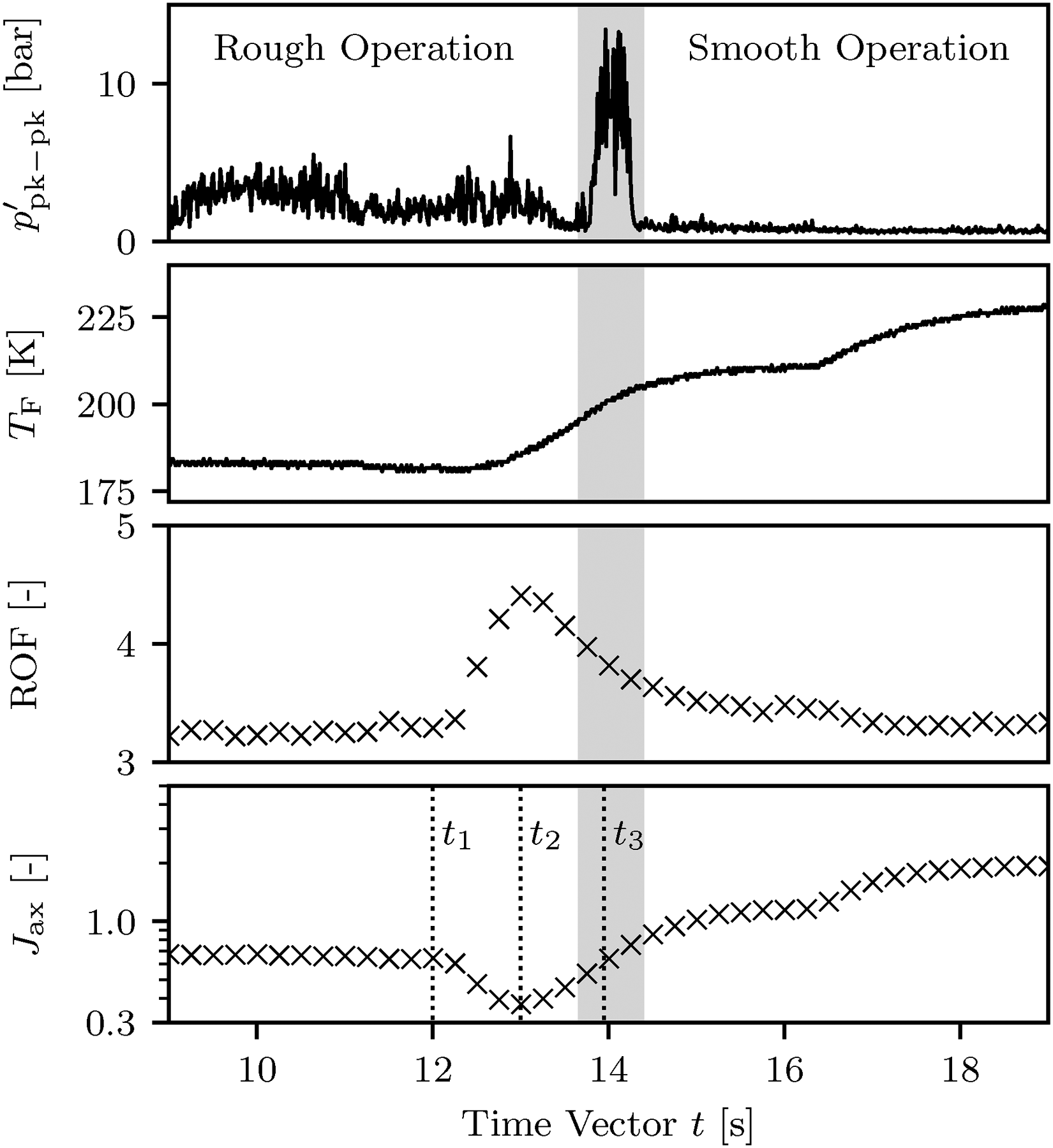
Time evolution of peak-to-peak unsteady chamber pressure signal
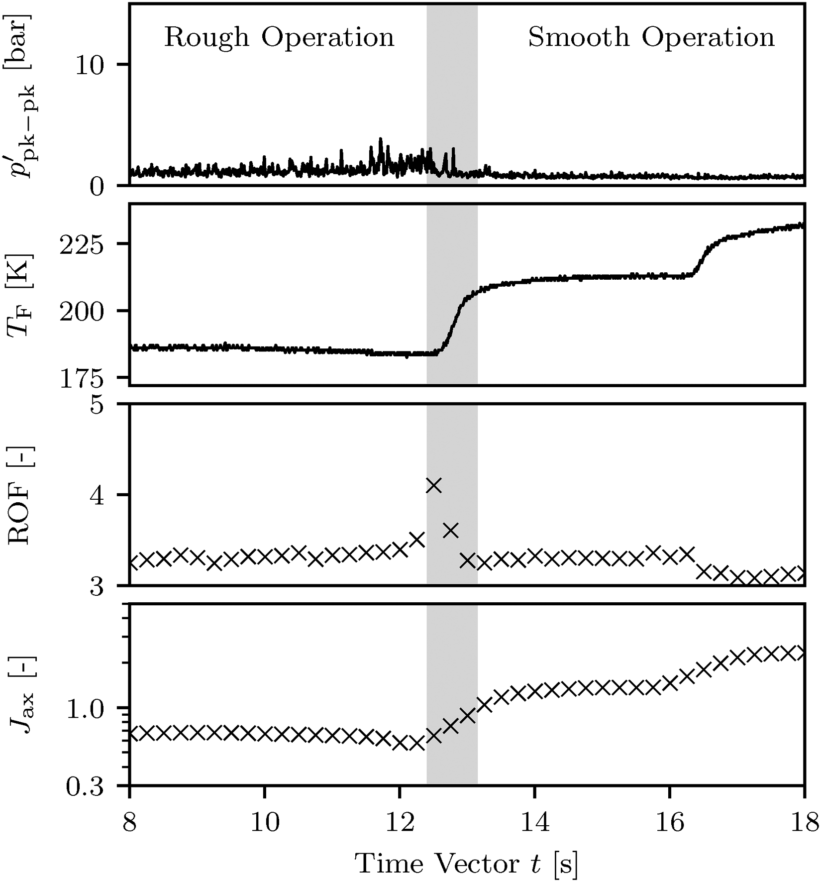
Time evolution of peak-to-peak unsteady chamber pressure signal
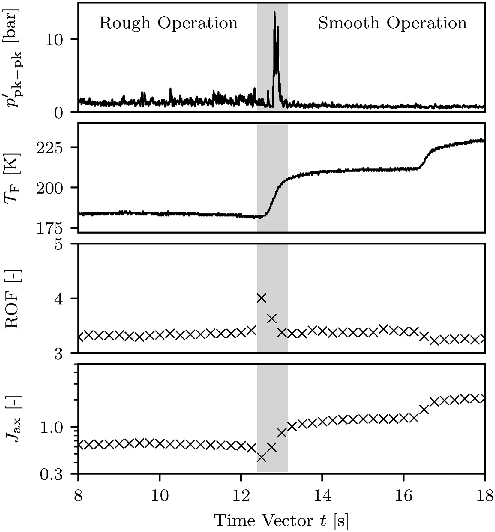
Time evolution of peak-to-peak unsteady chamber pressure signal
Table 4 lists the relevant injection parameters and the corresponding HF burst characteristics for the different FTR runs. It is to note that for the maximum
It can be seen that despite the relatively small differences in peak
Comparing the three HF burst characteristics, an assumed upper occurrence-boundary for the HF burst phenomenon could be defined between
HF burst characteristics and relevant injection parameters during frequency intersection time interval for the FTR test runs.
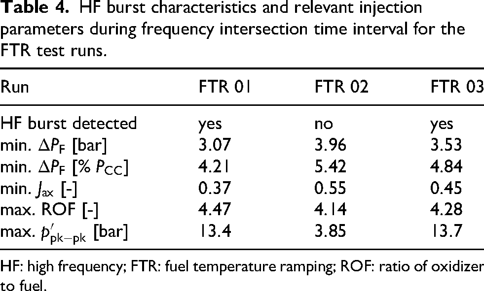
HF: high frequency; FTR: fuel temperature ramping; ROF: ratio of oxidizer to fuel.
Optical analysis of HF burst
To better understand the underlying mechanism behind the observed HF bursts, the high-speed flame images are analyzed in this section. The described phenomena are captured via the CH*-chemiluminescence imaging system at
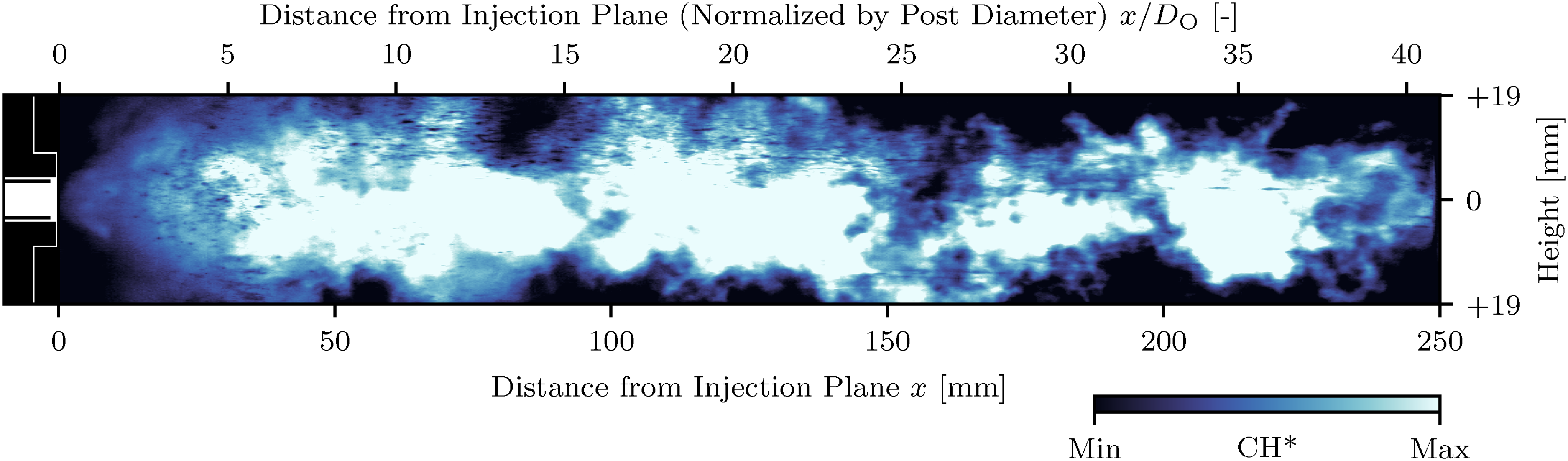
Instantaneous (single-frame) CH*-chemiluminescence flame image at
An instantaneous flame image corresponding to the operating conditions with the lowest momentum flux ratio (and the highest mixture ratio) at
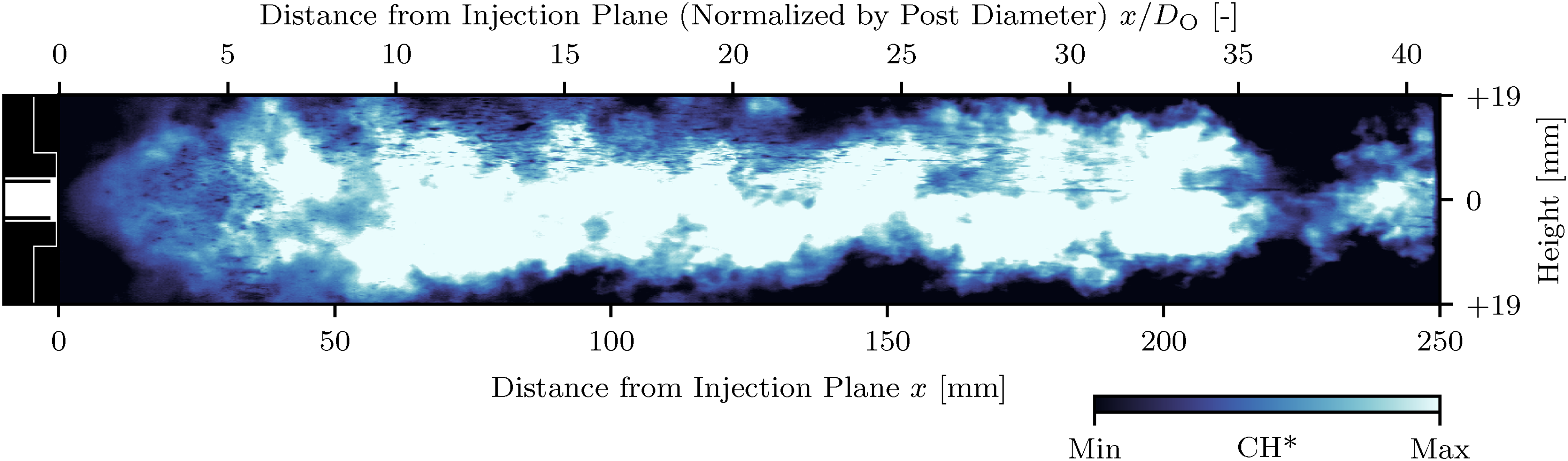
Instantaneous (single-frame) CH*-chemiluminescence flame image at
The highest unsteady pressure amplitude is achieved at
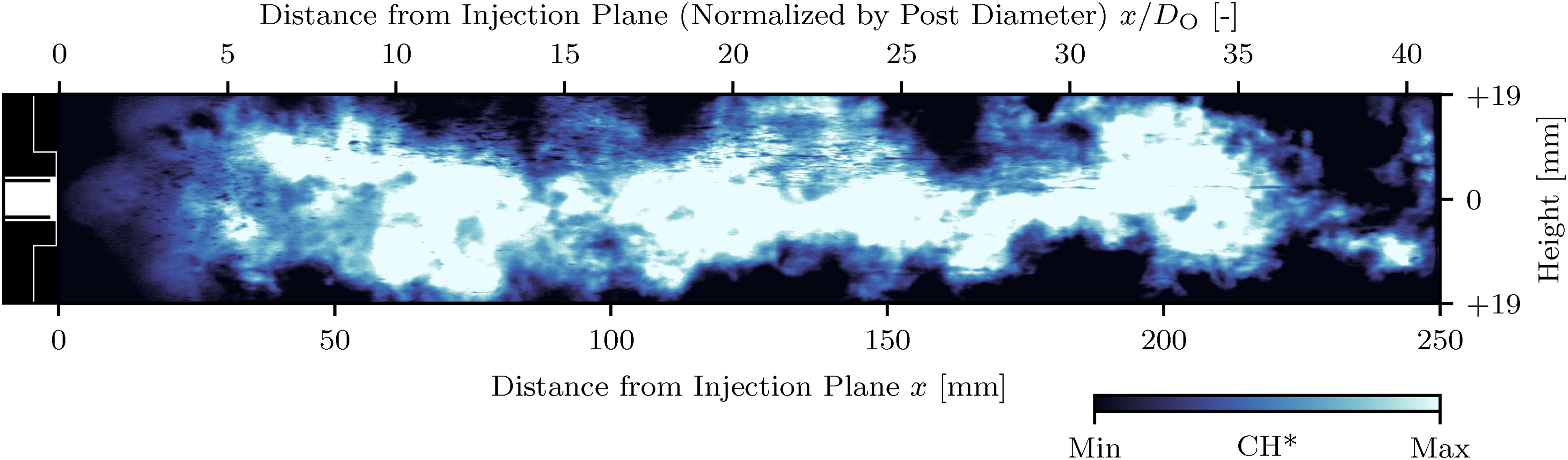
Instantaneous (single-frame) CH*-chemiluminescence flame image at
This distinct flame pulsation is visualized in Figure 22. Here, six instantaneous CH* emission images are sampled at the corresponding phase of the HF burst phenomenon. For visualization purposes, the contrast in these images is enhanced compared to Figures 19 to 21. At the start of the pulsation cycle in Figure 22(a), the flame is only loosely attached to the injector exit. There is no structured shape visible. Figure 22(b) subsequently shows the typical pulsating state with a short low-opening angle section followed by a sudden outward flame expansion. After this outward expansion zone is transported downstream the flame returns to a more uniform cone shaped structure, more akin to its nominal operating state (Figure 22(c)). This state however is again destabilized until it finally returns to the initial condition with a more chaotic flame structure at the injector exit in Figure 22(f).

Instantaneous near injector CH* flame emission images during different HF burst phases
The captured OH*-chemiluminescence images, while not offering the same spatial resolution and dynamic range of the CH* images, are available at
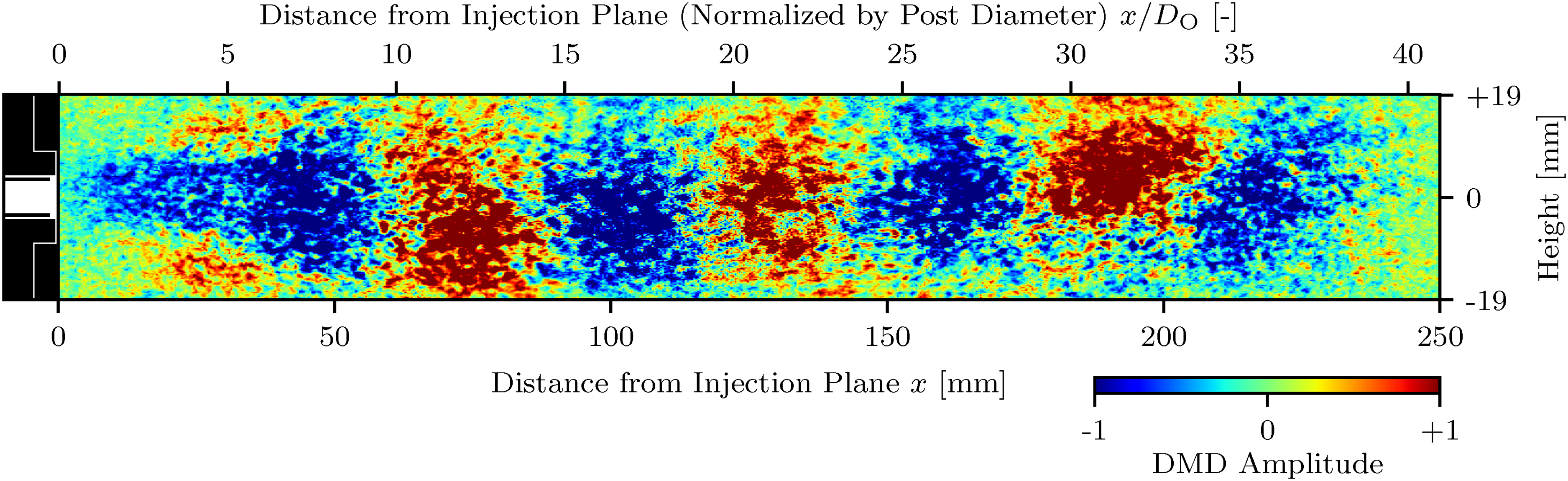
Dynamic mode decomposition (DMD) spatial mode (frequency: mode A,
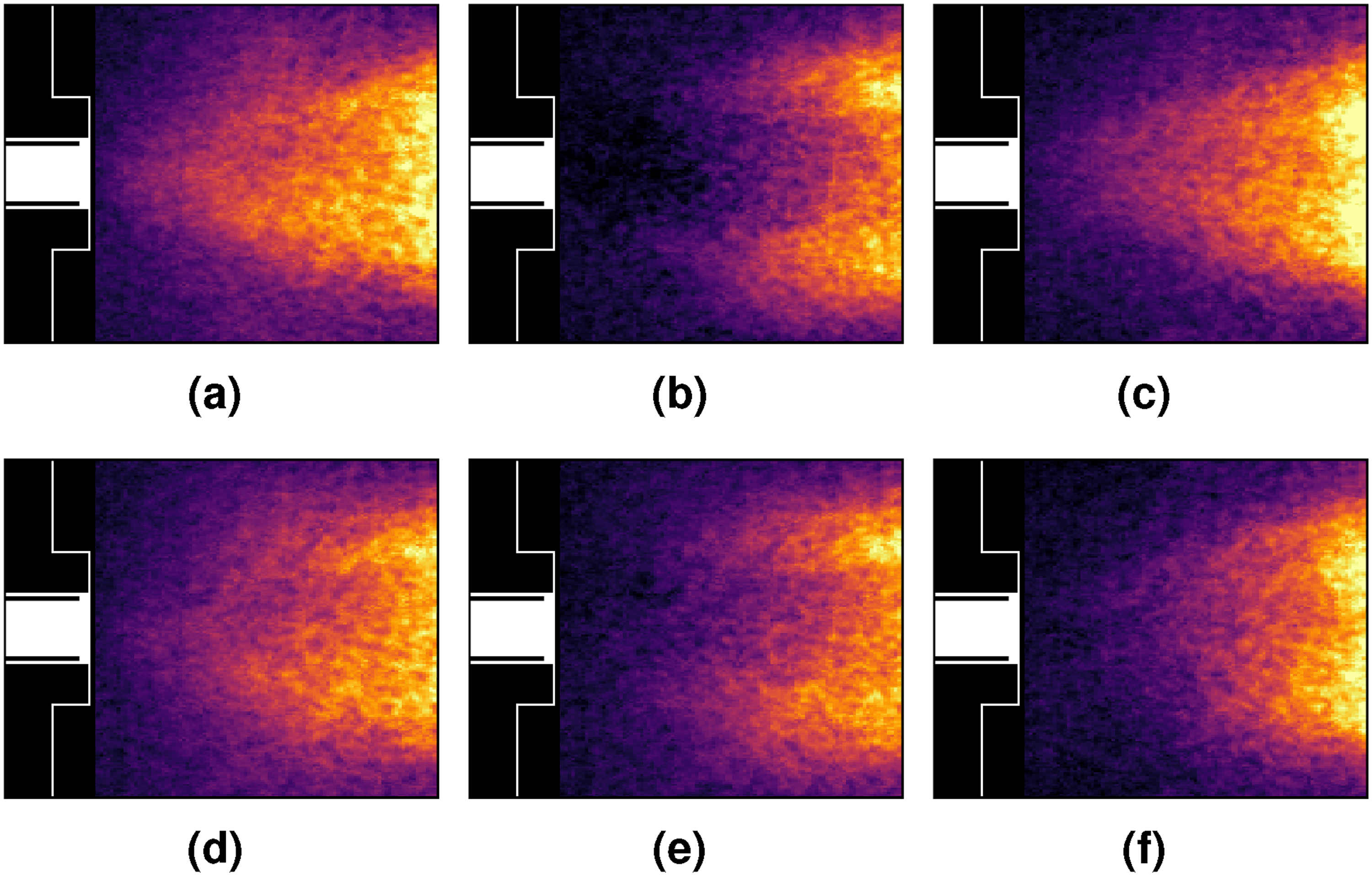
Reconstructed OH* dynamic mode decomposition (DMD) spatial mode frames (frequency mode A,
These findings of a radially pulsating flame close to the injector exit correlate well with the previous assumption that the observed excited frequency band A is indeed the first radial mode of the combustion chamber.
Proposed instability mechanism
With the combined information gathered in the previous sections a mechanism for the observed HF instability phenomenon is proposed:
At low fuel injection temperatures, the first radial mode of the combustion chamber is already slightly excited through coupling with the LOX injector acoustics. The change in operating conditions results in an intersection of the chamber mode, the LOX injector acoustics and a resonant frequency originating from the fuel side injector. This triple intersection of acoustic eigenmodes happens at low fuel-to-oxidizer momentum conditions, under which the flame is only weakly attached to the injector exit and, therefore, susceptible for disturbances. Acoustic resonance within the fuel injector, promoted by the low relative pressure drop, modulates the injected fuel mass flow. This modulation coupled with the, under these conditions, sensitive flame generates a strong outwards pulsation mode of the flame at the injector exit. A possible working principle of this interaction is sketched in Figure 25. A downstream propagating acoustic wave inside the fuel injector momentarily increases the injected mass flow and velocity, promoting mixing and resulting in an increase in the flame’s heat release (see Figure 25(a)). The increase in heat release leads to an increase in chamber pressure (Figure 25(b)). The subsequent upstream propagating acoustic wave (Figure 25(c)) decreases fuel injection momentum—thus causing the observed chaotic, barely anchored flame. This comes with an decrease in local heat release and chamber pressure. The next outward traveling wave inside the fuel injector repeats the cycle again. The interaction between the acoustic wave in the fuel injector, the heat release and the chamber pressure are also visualized in Figure 26. Here, the respective unsteady pressure signals in the combustion chamber volume and the fuel side injector manifold are shown within a selected time interval. Additionally, the normalized OH* emission intensity is plotted in the same interval. The emission intensity is extracted from the instantaneous OH* flame images as the cumulative image brightness in the near injector region (from This interaction mechanism is then sustained until the further increase in fuel injection temperature shifts the fuel injector eigenmode as well as again strengthening the flame anchoring.
The observed instability behavior shares qualitative similarities with classical thermoacoustic feedback mechanisms, in which coupling between unsteady heat release and acoustic pressure oscillations governs growth and saturation of oscillatory modes. For example, Keller et al.
21
demonstrated in pulse combustors that phase relationships between heat release and pressure fluctuations, governed by characteristic combustion time delays, can drive self-excited oscillations and limit-cycle behavior. While the present configuration significantly differs from pulse combustorsoperating conditions and propellant injection (premixed vs. non-premixed), these established frameworks could provide a useful qualitative basis for interpreting the observed dynamics. In the context of LRE specific investigations, the relation between the usteady pressure and the OH* intensity agree well with the previous findings by Gröning et al.
22
where a relatively constant phase shift between
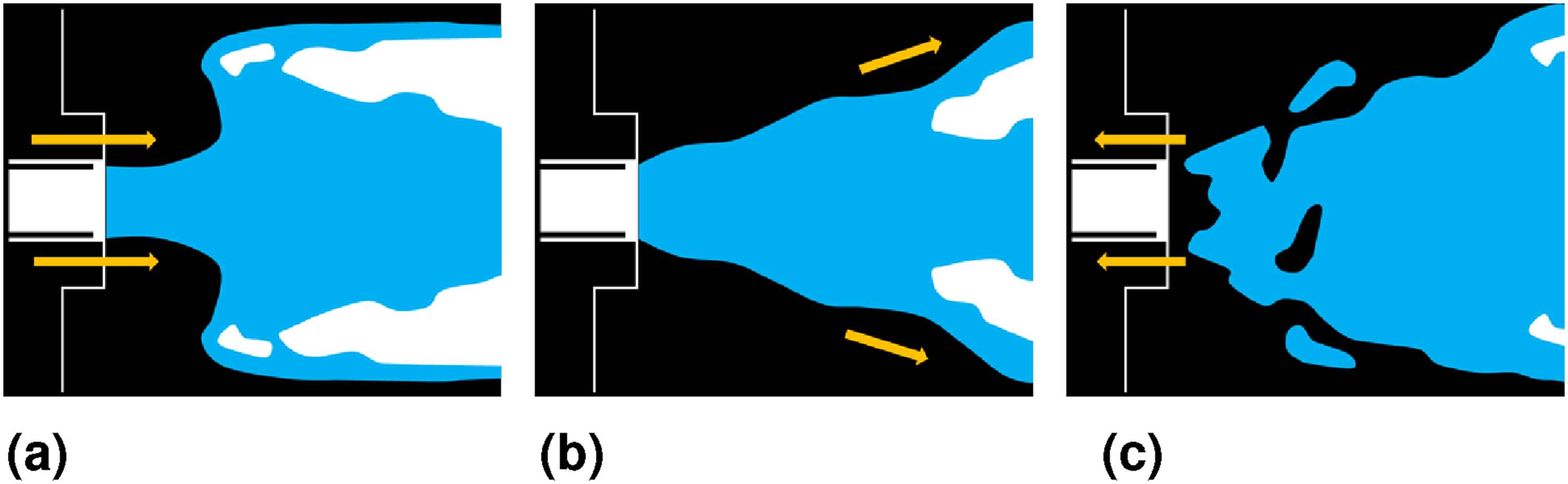
Schematic sketch of flame pulsation mode under acoustic fuel side modulation: (a) downstream wave propagation, (b) intermediate state, and (c) upstream wave propagation.
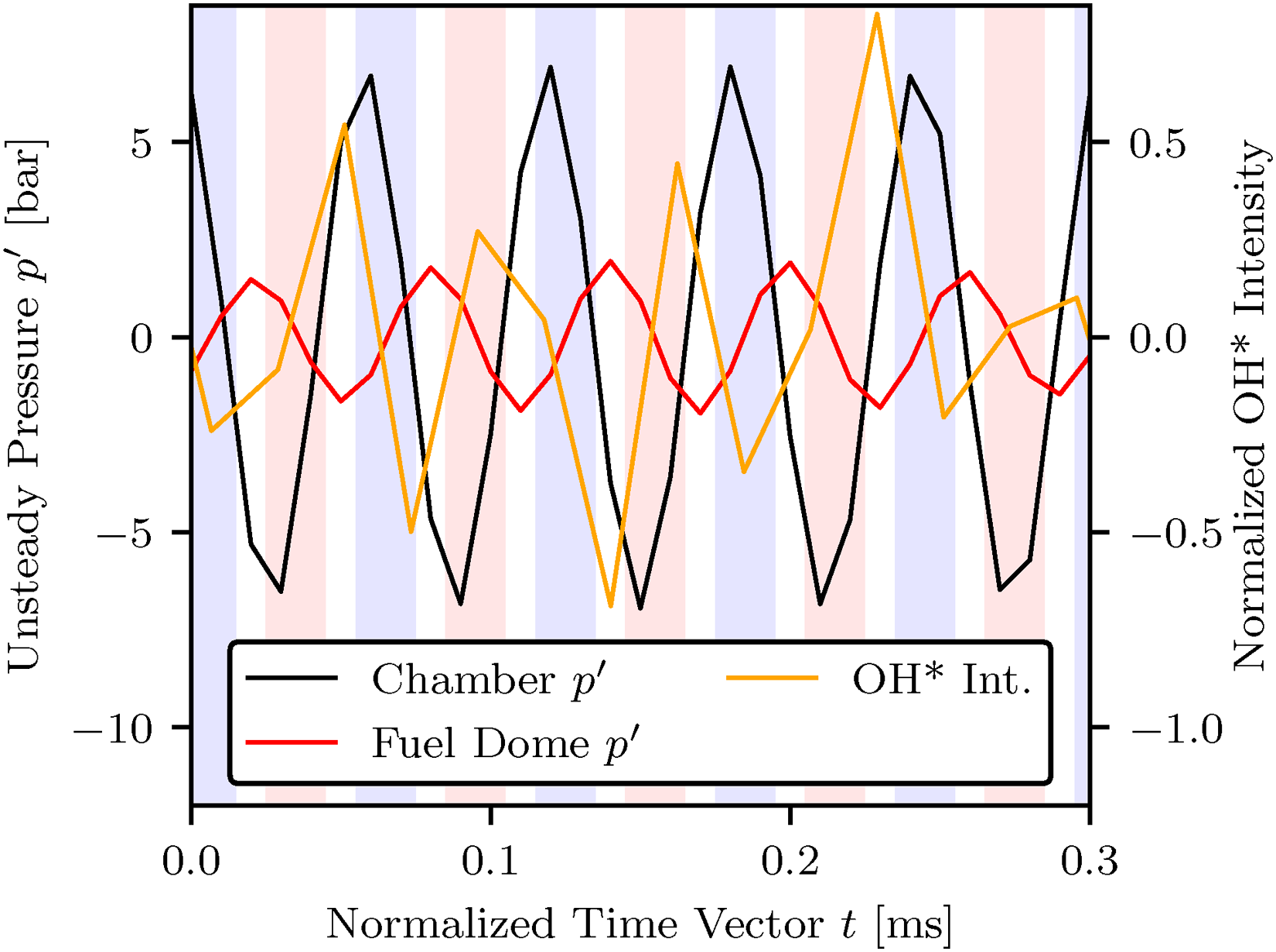
Time series of unsteady pressures
Stability limits for the swirl coaxial injector
As both the overly excitement of the higher chamber modes and the strong HF burst phenomena could be linked to off-nominal fuel injection velocities and, to that effect, off-nominal momentum flux ratios this section aims to experimentally define a global high-frequency stability limit for the swirl injector element within the given configuration. For this purpose, the high-frequency pressure oscillation characteristics during all five presented runs (NOM 01, NOM 02, and FTR 01
Starting with the fuel injection temperature itself (Figure 27) it becomes clear that while it is possible to draw a stability boundary at
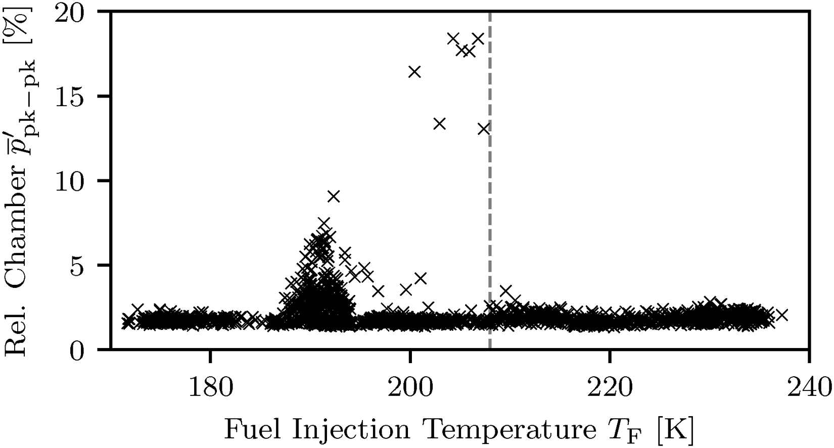
Relative peak-to-peak values of unsteady chamber pressure
As can be seen in Figure 28, the relative fuel side injector pressure drop offers a better correlation for defining a stability limit. In this case, the system shows unstable behavior only when
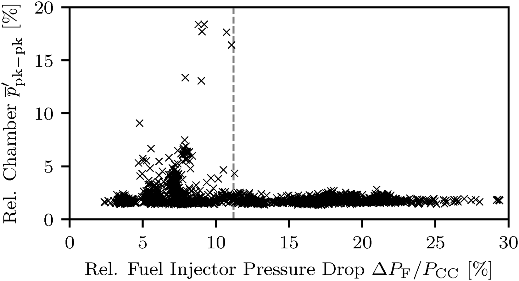
Relative peak-to-peak values of unsteady chamber pressure
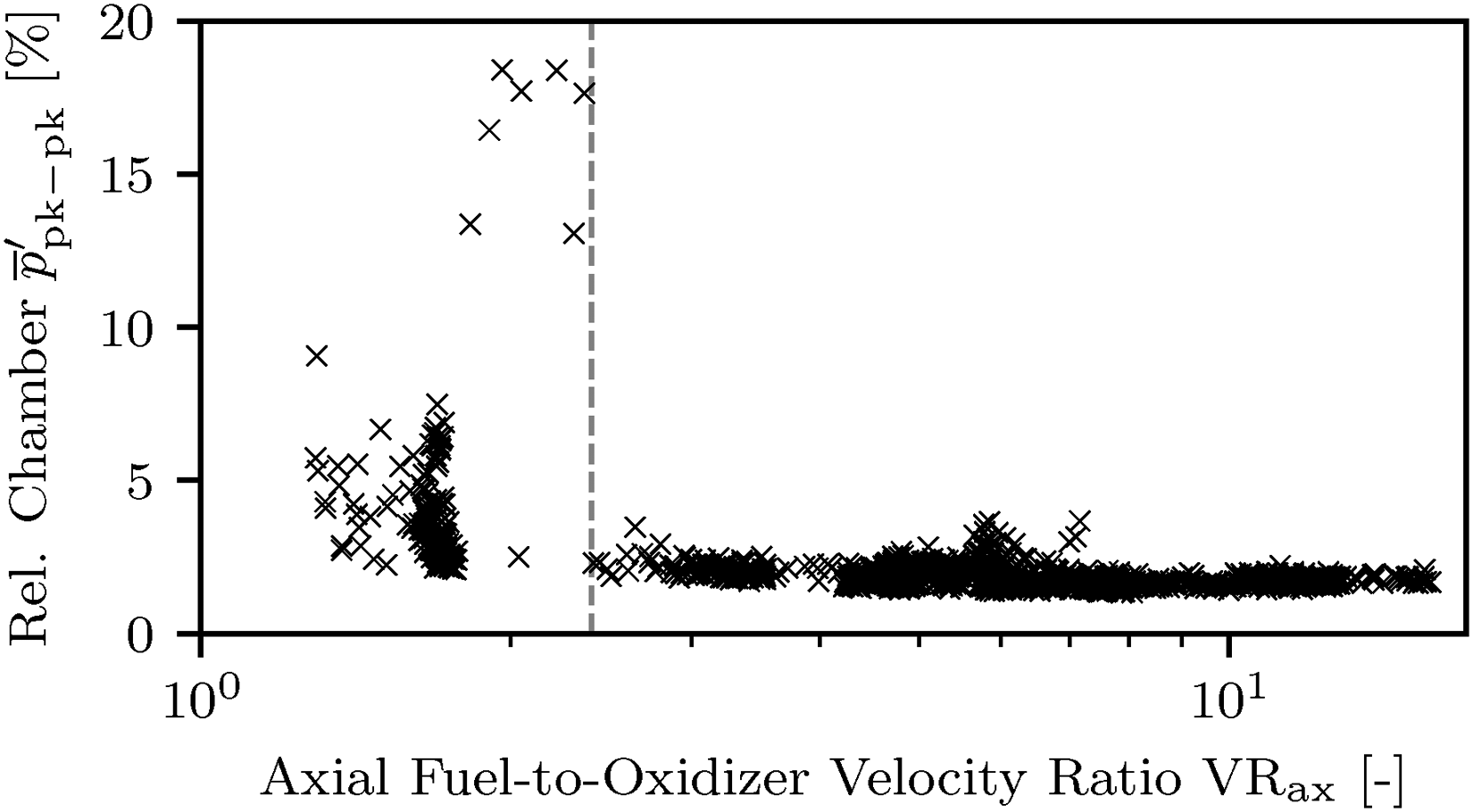
Relative peak-to-peak values of unsteady chamber pressure
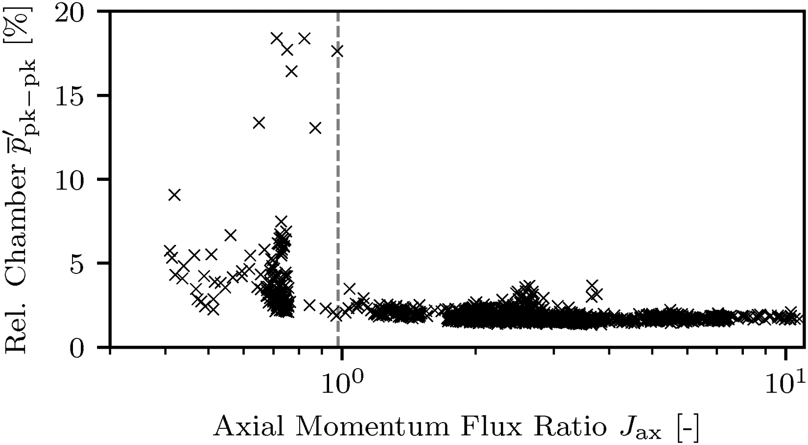
Relative peak-to-peak values of unsteady chamber pressure
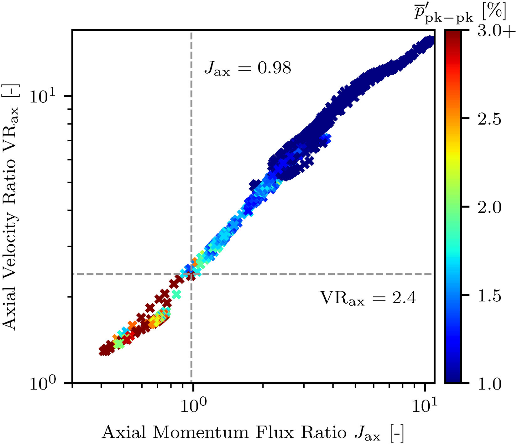
Relative peak-to-peak values of unsteady chamber pressure
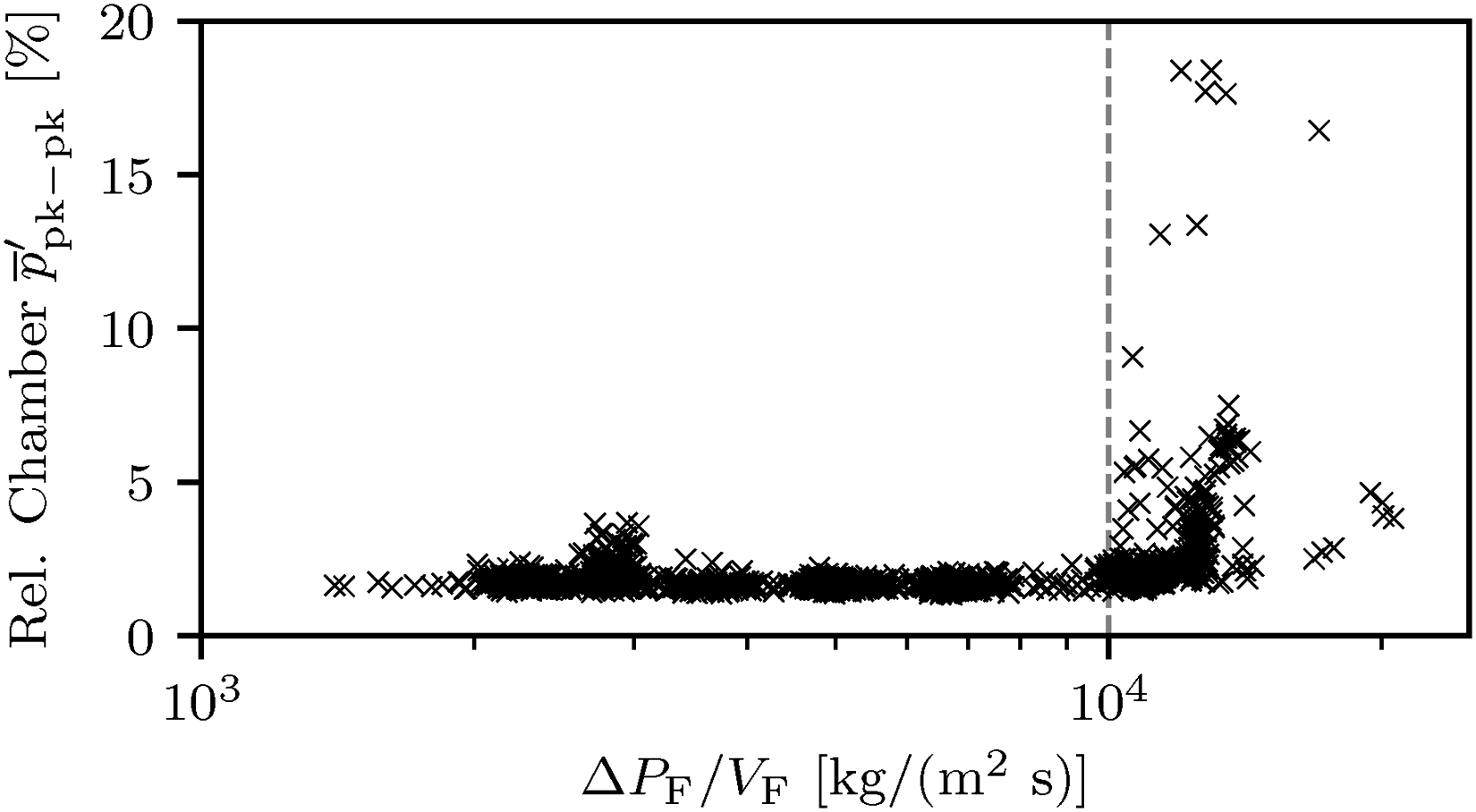
Relative peak-to-peak values of unsteady chamber pressure
It is to note that the stability limits presented here are only considered applicable to the given single-element combustor and the described instability mechanisms. The previously conducted analysis showed that the instabilities are not only an effect of injection parameters but additionally require acoustic interactions. Changing the geometric dimensions of components or testing the element in a multi-element combustion chamber (with more complex dynamics such as injector–injector interactions) could potentially shift these limits into either direction.
Conclusion
In this article, the effects of fuel injection temperature on the high-frequency combustion stability of a single swirl coaxial injector element are studied. It is found that for lower fuel temperature injection conditions below
This work also proposes a novel mechanism for the triggering of these instability phenomena for swirl injectors: The coupling of the fuel injector acoustics with the first radial combustion chamber mode under low fuel-to-oxidizer momentum ratio condition promotes the growth of chamber pressure oscillations. Under these conditions the flame is very sensitive to the resulting modulation of the fuel injection. This modulation leads to an outward pulsation mode of the flame in the near-injector region. The subsequent fluctuation in the heat release rate then drives the chamber pressure oscillations further resulting in the observed combustion instabilities.
Based on the findings of this study, a series of passive control methods and strategies for suppression of these instabilities can be thought of.
Operation of the injector element within the stable region with regard to momentum flux, injection velocity, and relative pressure drop (see Table 5). Variation of the fuel injectors geometric length to shift its respective natural frequency out of the vicinity of any possible chamber mode frequencies. Incorporation of a damping resonator within the fuel injector itself, similar to the ones invented by Armbruster.
23
This resonator could be an interesting option if the other options are not applicable.
Determined LSLs for the tested swirl coaxial injector element.
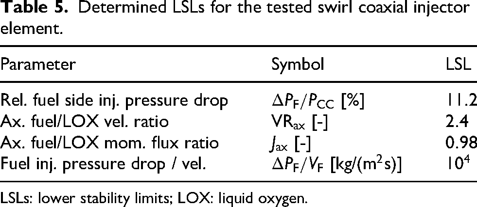
LSLs: lower stability limits; LOX: liquid oxygen.
The presented data in this study could also provide valuable information for future research in the form of inputs for equation parameters used in reduced-order oscillation models for LREs.
Footnotes
Acknowledgements
The experiments presented in this work were conducted in the frame of the DLR project NeoFuels. Special thanks to Alex Grebe, Markus Dengler and the entire P8 test bench team for the support in preparing and conducting the tests. Special thanks also to Prof. Dr Jan Deeken from RWTH University Aachen for the academic supervision of the work.

Funding
The authors received no external financial support for the research, authorship, and/or publication of this article.
Declaration of conflicting interest
The authors declared no potential conflicts of interest with respect to the research, authorship, and/or publication of this article.