
Abstract
Soft armour consisting of multi-layered high-performance fabrics are a popular choice for personal protection. Extensive work done in the last few decades suggests that shear thickening fluids improve the impact resistance of woven fabrics. Shear thickening fluid–impregnated fabrics have been proven as an ideal candidate for producing comfortable, high-performance soft body armour. However, the mechanism of defeating a projectile using a shear thickening fluid–impregnated multi-layered fabric is not fully understood and can be considered as a gap in the research done on the improvement of soft armour. Even though considerable progress has been achieved on dry fabrics, limited studies have been performed on shear thickening fluid–impregnated fabrics. The knowledge of simulation of multi-layered fabric armour is not well developed. The complexity in creating the geometry of the yarns, incorporating friction between yarns and initial pre-tension between yarns due to weaving patterns make the numerical modelling a complex process. In addition, the existing knowledge in this area is widely dispersed in the published literature and requires synthesis to enhance the development of shear thickening fluid–impregnated fabrics. Therefore, this article aims to provide a comprehensive review of the current methods of modelling shear thickening fluid–impregnated fabrics with a critical analysis of the techniques used. The review is preceded by an overview of shear thickening behaviour and related mechanisms, followed by a discussion of innovative approaches in numerical modelling of fabrics. A novel state-of-the-art means of modelling shear thickening fluid–impregnated fabrics is proposed in conclusion of the review of current methods. A short case study is also presented using the proposed approach of modelling.
Keywords
Introduction
A wide variety of monolithic and composite materials have been used as armour, depending on the threat levels expected in the battlefield. Metals and alloys (Ben-Dor et al., 2012), ceramics (Madhu et al., 2006), woven fabrics (Lee et al., 2013; Lim et al., 2003), polymers and combinations thereof (Mohotti et al., 2013; Serjouei et al., 2015) are among the most commonly used materials in armour.
Woven fabrics made of high-performance textile fibres in a multi-layered arrangement are an extremely popular choice for lightweight personal body armour (Bhatnagar, 2016; Cavallaro, 2011; Chen, 2016; Crouch et al., 2017; Nilakantan, 2018; Scott, 2005; Sparks, 2012; Yang et al., 2015). Textile fibres are viscoelastic in nature (Fujino et al., 1955; Hall, 1967) and multi-layered arrangements of elastic and viscoelastic materials may be assembled to mitigate pressure and impulse on a system (Rahimzadeh et al., 2015). It is obvious that by increasing the number of fabric layers present in a composite system, the protection level against projectile penetration can be increased. In fact, in order to defeat commonly used ballistic threats, approximately 20–50 layers of dry fabric layers are required (Lee et al., 2003). However, with an increasing number of fabric layers, the thickness, stiffness, mass and cost of the protective system also increase. This may cause such systems to be unsuitable for day-to-day use or military activities. This also contradicts with the general objectives of body armour research, to produce low-cost, lightweight and comfortable armour systems while preserving superior ballistic performance against various threat levels (Cunniff, 1992).
Given that the lives of users may depend on the performance of their armour, the design of such materials is not to be treated lightly, especially after the unfortunate performance failure of Toyobo fabric (commercially known as Zylon®) body armour which caused loss of lives of many law enforcement personnel (Crouch et al., 2017). In fact, there are strict performance standards published by the National Institute of Justice (NIJ; 2000a, 2000b). The NIJ standard for the ballistic resistance of body armour requires the back face signature (BFS) to be 44 mm at most for non-perforating projectiles (NIJ, 2000a). Even though capturing projectiles with no penetration is considered the minimum requirement, it may be insufficient to prevent injury completely (Prat et al., 2012). Non-penetrating projectiles could still cause serious injuries, even leading to death, as a result of behind armour blunt trauma (BABT) (Cannon, 2001). On the other hand, the deformation-only evaluation criteria employed by the NIJ standard provides insufficient protection (Gryth et al., 2007; Merkle et al., 2008). The BFS is required to be less than 25 mm according to the UK Home Office Scientific Development Branch (HOSDB) Body Armour Standards for UK Police (Croft and Longhurst, 2007). Even though ceramic and metallic plates have proven their worth in defeating high-velocity projectiles (Hazell, 2016), which could mitigate harmful consequences, accommodating such systems into personal body armour hinders its comfortability as well as concealability. Research is being carried out to incorporate such hard inserts into soft armour systems in innovative and efficient ways, with less compromise on wearer mobility (Martini and Barthelat, 2016).
Impregnating dry woven fabrics with shear thickening fluids (STFs) is a relatively newer approach to achieve the conflicting objectives of body armour research – superior ballistic performance coupled with comfort. STF-impregnated fabrics show enhanced ballistic resistance compared to dry/neat woven fabrics (Lee et al., 2003, 2013), thereby making it possible to achieve better ballistic performance than equivalent multi-layered dry fabric stacks. This phenomenon is extremely attractive to the defence and protective services industries since STF-incorporated body armour are more flexible, lightweight and comfortable compared with regular body armour made of dry fabric stacks. Lee et al. (2003) investigated the effects of STF impregnation on the flexural properties and areal density of Kevlar fabrics. It was found that STF-impregnated Kevlar fabrics are able to provide approximately similar impact resistance to that of the dry fabric layer counterparts of equivalent areal density. Adding more STF increases the areal density of the STF-impregnated fabric. However, since a lesser number of fabric layers are required, the STF–fabric composite is significantly thinner and consequently much more flexible than the dry fabric counterpart. Haris et al. (2015) reported enhanced shock wave mitigation capability in STF-impregnated fabrics which could help reduce trauma. These properties in combination make STF-impregnated fabrics a high-potential focus for next-generation body armour and the subject of extensive research on body armour for ballistic performance (Cao et al., 2017; Fahool and Sabet, 2016; Laha and Majumdar, 2016; Lee et al., 2003, 2013; Majumdar et al., 2013; Park et al., 2013, 2014; Petel et al., 2015; Wetzel, 2004) and stab resistance (Feng et al., 2014; Gong et al., 2014; Gürgen & Kuşhan, 2017b; Majumdar et al., 2013; Xu et al., 2017). Multi-phase STFs (MSTFs) have also been investigated in recent years for their better performance in comparison with biphasic STF-impregnated fabrics (Ávila et al., 2018; Gürgen & Kuşhan, 2017a, 2017b; Gürgen et al., 2016a, 2016b; Huang et al., 2015; Tan et al., 2018). Even though these studies have managed to capture some aspects of the elevated energy absorption capability of STF-impregnated fabrics, their behaviour is not fully understood (Majumdar et al., 2013). The complexity of destructive and high-speed testing makes it challenging to fully understand the dynamics of this process. Therefore, a purely empirical assessment, although useful, may not be ideal for studying the ballistic impact of STF-enhanced fabrics. However, this could very well complement armour research when coupled with computational analysis.
Computational analyses simulating ballistic impact on dry woven fabrics have contributed profoundly in elucidating the dynamics of defeating a projectile and contributing variables such as fabric structure/architecture (Yang et al., 2014), projectile geometry (Talebi et al., 2009), impact velocity (Shim et al., 1995), multiple ply interaction and orientations (Nilakantan and Nutt, 2018; Wang et al., 2015) and friction (Duan et al., 2005a, 2005b, 2006a; Rao et al., 2009a; Wang et al., 2016). However, out of these variables, friction between yarns has been identified as one of the most important parameters that influences ballistic performance. In fact, Gürgen et al. (2017), after an extended review study, concluded that the elevated energy absorption of STF-impregnated fabrics is primarily due to enhanced friction rather than shear thickening behaviour itself. Moreover, it is reported that STF impregnation facilitates fibre/yarn coupling by plugging the voids inside fabric structures, resulting in transmission of energy over a wider span of the fabric that would otherwise be borne mainly by the primary yarns. Primary yarns are generally defined as the orthogonal sets of warp and weft yarns that are directly in contact with the projectile (Duan et al., 2002). Therefore, the impregnation of STFs has proven to provide more efficient load bearing across fibres/yarns by increasing coupling between them. Fahool and Sabet (2016) studied the effects of STF impregnation on the tensile strength of Twaron fabrics. STF-impregnated fabrics showed markedly higher tensile strengths than the dry fabric counterparts. It was also observed that treated fabrics had much higher moduli. It was found that STF-impregnated fabrics have better tensile strengths and consequently impact resistance in comparison with dry fabrics (Fahool and Sabet, 2016).
The modelling of frictional interactions within fabrics undergoing ballistic impact alone is a challenging task. Even though the ballistic impact of STF-impregnated fabrics has been the subject of numerous empirical studies, there are only a limited number of studies reporting computational approaches or combinations thereof. Therefore, it is important to gather current knowledge and assess the suitability of previous work as an initiative for future work. This article presents a comprehensive review of the approaches in numerical modelling of STF impregnation of high-performance woven fabrics under ballistic threats. Reviews on shear thickening behaviour and related mechanisms, and different approaches to modelling fabric materials, precede the discussion on modelling STF-impregnated fabric composites. The article concludes by highlighting research gaps and providing possible future directions for research.
STFs
The history of STF usage in armour applications runs back as far as 1968, where Gates (1968) found that STF improves coupling between high-performance fabric layers against ballistic impact. However, after a three-decade silence, the interest of the research community was regained only after the pioneering work by the University of Delaware in collaboration with the US Army Research Laboratory (Lee et al., 2003). One of the reasons that may have contributed to this silence could be the conclusion by Gates (1968) that the usage of STF was uncompetitive even though it was tested against a 30-calibre ball and armour-piercing (AP) bullets. Nevertheless, STF reinforcement of multi-layered fabric arrangements has been subject to intense research, using an inert carrier liquid and hard, colloidal particles as the STF. The most popular choice of STF in high-performance fabric applications is colloidal fumed silica dispersed in polyethylene glycol (PEG) (Decker et al., 2005; Gürgen and Kuşhan, 2017b; Hasanzadeh et al., 2015; Lee et al., 2003, 2009; Park et al., 2013; Petel et al., 2013). Fumed silica acts as the hard, colloidal particles, while PEG acts as the inert carrier liquid. The content (volume fraction) of the hard particles must be high enough for the shear thickening effect to take place. Therefore, generally, STFs are dense, colloidal suspensions. The following section discusses shear thickening mechanisms and impregnation into fabrics which is necessary to understand in order to characterise the behaviour of STFs.
Shear thickening mechanism
Newtonian liquids obey Newton’s hypothesis which postulates that the shear stress is proportional to the deformation rate or the shear rate. The ratio of shear stress to shear rate is a constant and is called the dynamic viscosity (Eirich, 1956). For liquids in which the ratio of shear stress to shear rate is not constant, the same ratio is referred to as the apparent viscosity, which can vary with the rate of shear introduced to the system (Malkin and Isayev, 2017). STFs are classified as non-Newtonian liquids exhibiting abrupt rises in viscosity, sometimes even discontinuous, with increasing rates of shear (Wagner and Brady, 1999). A discontinuous rise in apparent viscosity is illustrated graphically from Zone III to Zone IV in Figure 1. Coloured dots in Figure 1 represent the colloidal solid particles in the STF (different colours are used for the purpose of clarity only). For high shear rates, the viscosity increase in these dense, colloidal suspensions could be so abrupt that the behaviour of the liquid transforms from liquid-like to solid-like. Several theories have been used to characterise the shear thickening phenomenon, even though some of these theories provide conflicting concepts. Order-to-disorder transition, hydrodynamic cluster (hydrocluster) formation theory and the contact rheology model can be identified as the established theoretical frameworks. Moreover, shear thickening behaviour is also dependent on many variables of the solid medium of the colloid, such as particle volume fraction (Jiang et al., 2010), particle size (Maranzano and Wagner, 2001b) and size distribution (Olhero and Ferreira, 2004), particle hardness (Kalman et al., 2008), interactions among particles (Maranzano and Wagner, 2001a) and different liquid media (Qin et al., 2017), as well as external factors such as temperature (Warren et al., 2015). A summary of these three theories which provide a perspective of the shear thickening mechanism is discussed below.

Variation of the apparent viscosity of an STF with increasing shear rate and graphical representation of particle arrangement according to proposed theories.
Dense, colloidal suspensions exhibiting shear thickening behaviour are inert carrier liquids containing solid particles. Figure 1 graphically illustrates the variation of apparent viscosity of a colloidal dispersion with the shear rate. It can be observed that with increasing shear rate, a colloid at equilibrium is rearranged to an orderly layered structure, causing a reduction in its apparent viscosity (also termed as shear thinning). However, upon further increasing shear rates, the ordered structure disappears to form clusters of the solid particles in the colloid, after a threshold shear rate is reached. The threshold shear rate causing an abrupt and discontinuous increase in apparent viscosity is called the ‘critical shear rate’. This is illustrated graphically in Figure 1 where the discontinuous increase in apparent viscosity takes place from Zone III to Zone IV at the critical shear rate.
Hoffman (1972) proposed the order–disorder theory to explain the shear thickening behaviour which he subsequently validated with experimental results. Order–disorder theory postulates that inter-particle forces in the suspension interact with the forces of the shear field resulting in a layered flow for shear rates below the critical shear rate. At the critical shear rate, the shear stress on the layers is just enough to overcome inter-particle forces, causing the layers to roll up into eddies, resulting in a disordered flow. This is claimed to cause the abrupt increase in apparent viscosity according to the order–disorder theory (Hoffman, 1972). Since the viscosity increase is due to the disordered layered flow, this theory requires particles to be arranged in a layered structure before the onset of shear thickening in the suspension. Such a layered arrangement of flow is illustrated in Zone II in Figure 1.
Bossis and Brady (1989) proposed a different approach to explain the shear thickening phenomenon using hydrocluster formation based on Stokesian Dynamics simulations. According to the theory proposed, shear thickening behaviour is due to the formation of large clusters of solid particles. Shear thinning is due to the disappearance of the direct Brownian contribution to the viscosity of the suspension, thereby causing easy flow. At high shear rates, inter-particle forces in the suspension are overcome by hydrodynamic forces induced by the shear field. This causes solid particles to group together to form large clusters called hydroclusters, resulting in strong lubrication forces, abruptly increasing the apparent viscosity. This theory is supported by subsequent research work employing small-angle neutron scattering (Maranzano and Wagner, 2002), rheo-optical methods (Bender and Wagner, 1995) and Stokesian Dynamics computer simulations (Boersma et al., 1995). Such hydroclusters are graphically illustrated in Zone III in Figure 1 (green). However, these hydroclusters can be formed without a layered structure present at the onset of shear thickening, which contradicts the order–disorder theory. Subsequently, Hoffman (1998) reported that there may be cluster formations after the instability of flow is created by the critical shear rate, even though he argues that hydroclusters alone do not play the major role in shear thickening.
A relatively new approach pioneered by Melrose and Ball (2004a, 2004b) using Stokesian Dynamics simulation of a model system in its continuous shear thickening regime is the contact rheology model. This associates the shear thickening transition in concentrated colloids with the growth of a network of close particle contacts and shear-induced density variations. This network is illustrated graphically by red lines in Zone IV in Figure 1. These networks of contact relate directly to change in normal stress, and shear thickening is regarded as an approach to jamming. These structures cause resistance to shear deformation, thereby inducing an abrupt increase in apparent viscosity of the system according to the contact rheology model. Moreover, it is postulated that the extreme jump in apparent viscosity is realised by the contact networks’ contribution for exponential stress transmission, whereas at the onset of thickening, a purely hydrodynamic effect is insufficient to cause such an abrupt increase and is only sufficient to cause mild thickening (Catherall et al., 2000).
Impregnation of STF into woven fabrics and behaviour under impact loading
Even though it is alternatively known by the name ‘liquid body armour’, STF-reinforced armour does not present a liquid layer before or after the material. Instead, these dense colloids are intercalated into the fabric structure using a number of methods. The most common method is to dilute the highly viscous suspensions in alcohol to decrease the viscosity, thereby reducing surface tension by dampening the fabric material sufficiently. Uniform application of STF must be ensured, usually achieved by applying pressure using a padding arrangement which removes excess STF from the fabric. Added alcohol can subsequently be vaporised using a hot air oven without affecting the final composition (Srivastava et al., 2012).
Empirical studies on STF-impregnated fabrics available in the literature are of two main categories; ballistic impact tests or stab tests on STF-impregnated targets and yarn pull-out tests. Such empirical studies are key to validating numerical models. Therefore, it is important to gauge as to what empirical evidence is available to validate numerical models. The majority of the empirical studies are ballistic impact tests (Arora et al., 2019; Ávila et al., 2018; Khodadadi et al., 2019; Lee et al., 2003) and stab resistance (Gürgen and Kuşhan, 2017b, 2017c; Xu et al., 2017). Yarn pull-out studies are also available in the public literature which is considered a metric of energy absorption during ballistic impact (Bai et al., 2019; Feng et al., 2018). The most commonly used metric in ballistic impact studies is the residual velocity. Measuring the residual velocity of a projectile can be much easier than measuring BFS on a backing material or other metrics. High-speed cameras can be used to capture the impact behaviour which could later be used to observe deformation profiles as well as dynamic failure of fabrics. However, such results are not commonly available in the public literature. Residual velocity alone may not be sufficient to assess the compliance of a numerical model with experimental results in impact simulations since at large-impact speeds, the resistance to perforation is dominated by the material density, whereas at low-impact speed, the strength of the material is dominant. Post-perforation images can also be used to compare failure characteristics between empirical and numerical work. Yarn pull-out tests provide characteristic force–displacement curves that have been used for numerical calibration purposes. Merits and demerits of such calibrations are discussed in detail in section ‘Approaches to numerical modelling of STF-impregnated fabrics’.
Lee et al. (2003), in their pioneering work on STF-impregnated Kevlar, reported that the increased energy absorption of the composite material may be a result of increased pull-out resistance caused by intercalation of STF to the fabric. This resulted in increased loads on the yarns during impact, subsequently resulting in absorption of additional energy through fibre deformation and fracture. It was suggested that STF constrains the Kevlar yarns/fibres as they are pulled through the fabric under ballistic loading. A similar outcome has been reported by Majumdar et al. (2013) in their study to determine the energy absorption modes of an STF–Kevlar composite, thereby reinforcing the previous claim. Energy versus time curves plotted in their study were divided into three zones: Zone 1 – Elastic Zone, Zone 2 – Slippage/breakage Zone and Zone 3 – Failure Zone. It was observed that in the elastic zone, the energy was absorbed by yarn de-crimping and extension, followed by a stick-slip-like fluctuation of force in the second zone, before failure in Zone 3. Energy–time curves were elongated for untreated fabrics in comparison with treated ones, implying that less energy was absorbed by the untreated fabrics. This was concluded to be a result of yarn pull-out. The treated fabrics showed a sudden, catastrophic failure in contrast to untreated fabrics. It was concluded that yarn or fibre fracture was the dominant energy absorbing mode for treated fabrics, in contrast to yarn pull-out for untreated fabrics. Lee et al. (2003) carried out ballistic testing at 244 m/s, while Majumdar et al. (2013) used a dynamic impact tester at a speed of only 8 m/s. It has been proven that the impact velocity plays a major role in determining the mode of failure of a fabric. Five different categories of personal body armour are specified by NIJ (2000a). Type IIA armour, the category that requires a minimum ballistic performance, are tested against 9 mm and .40 Smith & Wesson Full Metal Jacket (FMJ) projectiles with approximate projectile velocities of 373 and 352 m/s, respectively. Type IV armour or plate inserts are tested against .30-calibre AP bullets (US Military designation M2 AP) at 878 m/s (NIJ, 2000a). When subjected to higher velocity projectiles, yarns tend to shear without extension to failure. Projectiles with a velocity exceeding a threshold called the critical velocity will cause the yarns to rupture instantly without allowing fibres to undergo extension (Cheeseman and Bogetti, 2003). Park et al. (2014) tested STF-impregnated Kevlar fabrics (KM2) at velocities ranging between 1 and 2 km/s using a two-stage light gas gun. Even though the experiment clearly showed that using STFs is advantageous (approximately 70% enhanced specific energy absorption performance over neat Kevlar), the underlying mechanism was not laid out clearly. They observed yarn pull-out to be significantly less than for neat Kevlar fabrics, similar to low-velocity impact scenarios mentioned earlier. Moreover, the signature pull-out pattern of the primary yarns in the shape of a cross was not observed on the first ply in contrast to the fifth ply in the Kevlar specimen with five layers. A higher degree of localisation was observed in STF–Kevlar composites, which has been attributed to the increased rigidity of the fabrics as a result of shear thickening behaviour upon impact. Discrepancies in energy absorption patterns in the experimental results and simulations were observed. Therefore, Park et al. (2014) concluded that the initial assumption of friction-dominant energy absorption is insufficient to fully characterise STF impregnation into fabrics. There has hitherto not been one single model or concept that could perfectly elucidate the underlying energy absorption mechanisms of STF-impregnated fabric systems under impact loading, which in turn makes it a stimulating area for research. A purely empirical assessment, however, may not be sufficient for this purpose, given the complexity in terms of the number of variables, destructive testing, high lead times, high speeds involved and cost of experiments. Therefore, complementing empirical studies with numerical analyses is beneficial in that context. Numerical modelling of STF-impregnated fabrics for impact loading is a challenging task and literature available is therefore scarce. However, there have been a few cases mentioned in the literature where researchers have attempted to numerically model STF–fabric composites (Hasanzadeh et al., 2017; Lee and Kim, 2012; Mirrahimi et al., 2017; Park et al., 2015), which is discussed in detail in the following sections.
Numerical modelling of fabrics
Numerical modelling
Owing to its versatility, numerical modelling has gained popularity among many disciplines, including research into the design and optimisation of armour materials. ‘Divide and conquer’ algorithms are employed in finite element analysis where the problem is broken down and solved in an iterative manner. Each iteration generates incremental strain/stress in elements, leading to deformation and/or failure according to the corresponding constitutive equation of the material (Saleh et al., 2017). Numerical modelling allows comprehensive solving of highly dynamic and complicated scenarios, such as ballistic impacts, with relatively lower cost and lead time (Saleh et al., 2017). Highly complex and hierarchical geometries such as those in fabric materials can be modelled at different resolutions (microscopic, mesoscopic and macroscopic) in two-dimensional (2D) and three-dimensional (3D) domains. Boundary conditions can be introduced easily in comparison with empirical testing, where different clamps have to be employed to alter the boundary conditions. Material properties can be programmed with a constitutive material model defining stress–strain behaviour, while failure criteria can be pre-specified using a fracture-initiation and property degradation algorithm. Projectile geometry and trajectory can be easily varied from armour-grade ammunition to a rigid metallic rod. Contact between fibre/yarn/fabric can also be defined using various contact algorithms which include information such as friction between elements. One of the main advantages of numerical simulation is its ability to produce highly informative results. This includes information such as stress–strain behaviour, contact forces, failure patterns and residual velocity. As such, it is a highly useful approach to capture the underlying dynamics of energy absorption that would otherwise be impossible to determine through empirical methods. However, the numerical modelling process must be used carefully every step of the way and sufficiently validated, since improper inputs and problem definition will yield misleading outputs (Lemaitre and Desmorat, 2005).
Various approaches to numerical modelling of fabrics
There are many different numerical approaches used to model the behaviour of fabrics under projectile impact and penetration. Numerous innovative methods have been developed over the years, starting from early 1970s, to model impact loading scenarios on fabric materials. With the rapid growth in computational power due to the introduction of high-performance computing (HPC) clusters, numerical models have seen a steep improvement in capturing complex numerical problems such as the ballistic performance of fabrics. An overview of different numerical approaches to date, based on model complexities, is presented herein.
The modelling approach employing one-dimensional (1D) pin-jointed orthogonal bars to represent woven flexible fabric yarns can be identified as the simplest among these methods and is efficient in terms of computational time. Roylance et al. (1995) developed a numerical model with the ability to model multiple-layered fabric panels, multiple projectile geometries and fabric imperfections such as yarn slippage at crossovers and different boundary conditions (Houghton and Roylance, 1989; Roylance et al., 1973; Roylance and Wang, 1978, 1981). This work, however, lacked the capability of modelling interactions between fabric layers in multi-layered arrangements, which is one of the most critical parameters for the performance evaluation of such a system. Moreover, they also assumed Hookean behaviour for these elements. The direct analysis approach used is relatively simple and understandable. The model is computationally inexpensive and helpful in elucidating and establishing primary relationships between ballistic impact and energy absorption and was an inspiration for further research work. Billon and Robinson (2001) also used pin-jointed bar element models to predict the ballistic limits of fabrics and the residual velocity of a projectile. Cunniff et al. (1998) modelled fabric as a collection of weighted nodes connected by mass-less fibre elements coupled with springs (schematic figure shown in Figure 2), revealing the importance of yarn de-crimping upon ballistic impact. These models, however, are unable to represent the strain rate sensitivity of fabrics. As a remedy, Shim et al. (1995) modelled ballistic impact using the same approach but in contrast to the previous models used a three-element spring–dashpot model to represent the viscoelastic behaviour of fibres and capture strain rate sensitivity. Tan and Ching (2006) developed a fabric model reflecting its orthotropic properties, the viscoelastic nature of the yarns, crimping of yarns, sliding contact between yarns and yarn breakage using an assembly of viscoelastic bar elements. Despite the modest number of degrees of freedom in this model, it yielded considerable agreement between the experimental and numerical results. In general, the finite element mesh has to be in the scale of the fabric structure, which is not practical when it comes to general use of pin-jointed bar models. Moreover, contact dynamics and transverse pressure loading are not well captured in this type of modelling method.
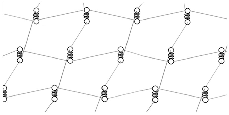
Modelling fabrics using pin-jointed bar elements.
Shell elements in combination with pin-jointed bars were also used by various researchers to model fabrics. Johnson et al. (1999) developed a computational model of fabrics by considering them as a 2D shell using both bar and shell elements. The model consisted of bar and shell elements arranged in an orthogonal grid. Fibres were simply designated to fail at the corresponding failure strength, while changes in strain employed a Lagrangian approach. Yarn crimp was simulated by bar elements with the assumed bilinear stress–strain relationship, while the contact surfaces for impact and shear stiffness were provided by shell elements. In their computational micro-mechanical material model of a loosely woven fabric, Ivanov and Tabiei (2004) represented yarns simply by the pin-joint mechanism of straight viscoelastic bars connected at the middle crossover point by a rigid link. A user-defined material subroutine (UMAT) was used in the commercial software package LS-DYNA for the simulation. Frictional forces at yarn crossovers were accounted for and used to determine rotational frictional elements dissipating impact energy. In addition, yarn de-crimping was also accounted for, yielding a good agreement between simulated and experimental results. However, the slippage of the yarns at crossover points was neglected even though rotational friction was accounted for. These models provided good computational efficiencies, which was important at the time of development when computational power was miniscule compared to today.
Lim et al. (2003) simulated the ballistic impact on high-performance Twaron fabrics using a model composed of membrane elements employing viscoelasticity and a strain rate–sensitive failure criterion. The model assumes the fabric as a continuum as well as isotropic, without accommodating yarn crimp or cross-section geometry. This effort neglected frictional effects between warps and weft yarns, which has now been proven to be the main source of energy dissipation during ballistic impact. In addition to friction, unravelling and fraying of yarns were also not accounted for. Moreover, the observed deformation under impact loading was conical in contrast to the pyramidal deformation observed in reality. Therefore, the signature cross shape of the pulled-out primary yarns could not be observed. The conical and pyramidal deformations are shown in Figure 3(a) and (b), respectively.
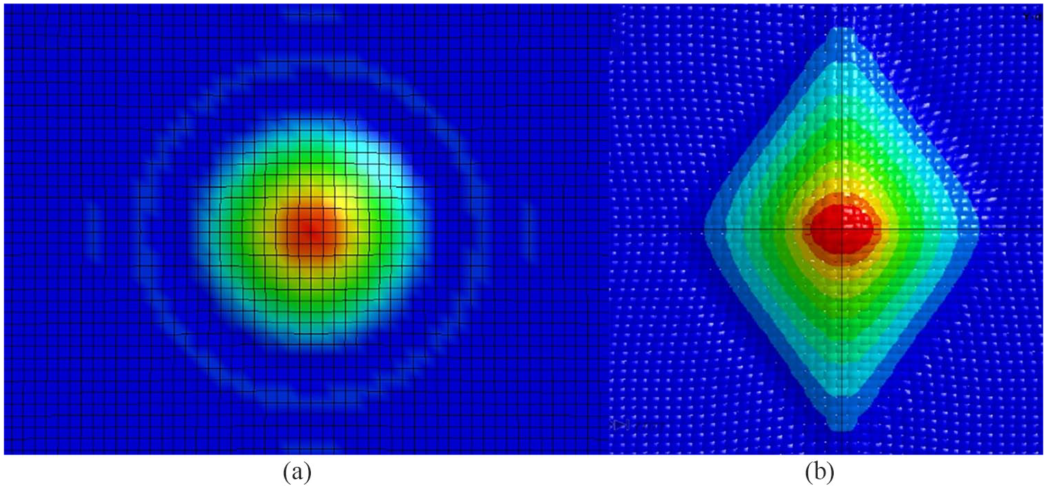
(a) Conical deformation of the models and realistic (b) pyramidal deformation.
Phoenix and Porwal (2003) used an analytical approach to develop a 2D membrane model to study the ballistic response and V50 performance of multi-ply fibrous systems. Assuming constant projectile velocity, self-similar solution forms for the tensile implosion wave and the curved cone wave were first developed. An approximate solution for the membrane response, including cone wave speed and strain distribution, was then obtained using matching boundary conditions. Subsequently, the cone velocity, displacement and strain concentration versus time were obtained considering the deceleration of the projectile due to resistance by the membrane. Porwal and Phoenix (2005), in their subsequent study, modelled system effects of ballistic impact into multi-layered fibrous materials, using the same approach. However, similar to the 1D modelling approach, inter-layer interactions could not be evaluated in this model. In general, macroscopic modelling approaches assuming fabrics as homogenised membranes are unable to capture inter-yarn friction, which is one of the most important mechanisms of energy dissipation in ballistic impact. Moreover, yarn de-crimping and crimp translations are absent due to the homogeneity of the fabric.
Shell elements have been used to model fabrics for better resolution in the meso-scale. Shell elements have at least two integration points through its thickness, in contrast to membrane elements which have only one integration point (Hallquist, 2006). Therefore, both bending stiffness and thickness changes can be better captured using shell elements than membrane elements. The location of through-thickness integration points of shell elements in LS-DYNA varies according to the database (d3plot or ASCII database elout), number of shell integration points written to the d3plot database and the different quadrature rules (Livermore Software Technology Corporation (LSTC), 2018a). Figure 4(c) and (d) graphically illustrates the location of through-thickness points for the case of five integration points, according to two different quadrature rules in LS-DYNA, Gauss and Trapezoidal, respectively. Shell elements are used to generate the geometries of the yarns (outer surface) in a more detailed manner which allows capturing inter-yarn frictional interactions, thereby allowing more realistic modelling of fabric materials for impact-related scenarios. Ha-Minh et al. (2013) numerically analysed ballistic impact on Kevlar fabrics at both meso- and macro-level fabric resolutions. Two meso-scale models were created with four and eight shell elements in a yarn cross-section with uniform nodal thicknesses. This is graphically illustrated in Figure 4(a) and (b). The results were significantly different under low-velocity impacts, but less variation was observed under high-velocity impacts. Two through-thickness integration points were used for the shell elements in this study, accounting for both bending stiffness and thickness change, as described above. This type of model can be generally illustrated as shown in Figure 5(a). Lee and Kim (2012) used the same approach with three shell elements in a yarn cross section to study the effect of STF impregnation of woven fabrics. The same model was used in the following study to analyse high-velocity impact on STF-impregnated fabrics (Park et al., 2015). However, varying thicknesses at the shell element boundaries in this approach can be problematic as a shell element cannot be assigned a variable thickness. However, it is imperative that the inter-yarn sliding interactions be represented correctly for accurate results. This also causes a loss of yarn material at the regions of the thickness variations, leading to a loss in yarn mass. To account for the reduction in mass, manipulation of density or thickness is necessary. This would cause errors in wave velocities and the geometry of the fabric, respectively. Nilakantan (2010) developed a new method for modelling shell yarns with variable nodal thicknesses to represent the contours of the yarn cross section more precisely than shell elements with uniform nodal thicknesses. This approach made it possible to provide a better approximation of a yarn cross-section geometry as well as its mass. Shell element usage at meso-scale modelling has proven its use as a less computational resource-demanding approach. However, at the point of impact on the fabric, solid elements can better capture curvature at contact surfaces and transverse effects such as transverse yarn compression, shearing and bending which are primarily due to projectile–yarn interaction. Solid elements are, however, more computationally expensive than shell elements, which essentially means that there is a trade-off between accuracy and computational expense when choosing between solid and shell elements for numerical simulations. Moreover, relatively negligible flexural stiffness of yarns/fabrics in comparison with their tensile stiffness poses a challenge in modelling. When a relatively high tensile modulus is assigned to yarn/fabric materials, this results in unrealistic, excessively high flexural stiffness when multiple solid elements are used through the thickness. Similarly, having multiple integration points through the thickness also endows the yarn/fabric with a high flexural stiffness. Tapie et al. (2018), Tapie et al. (2017), Tapie et al. (2016) and Nilakantan et al. (2011) used one solid element through the thickness in their fabric models. This approach, while reducing the flexural rigidity, also curtails computational cost by reducing the total number of elements used. In the commercial finite element code LS-DYNA, this may be further associated with the built-in hourglass forms, such as enhanced assumed strain stiffness hourglass form (LS-DYNA Type 9) (LSTC, 2012). However, in this approach of using a single solid element with reduced integration through the yarn thickness, only one central integration point is used to calculate element stresses. This also makes it impossible to calculate flexural rigidity, since at least two integration points through thickness must be available for that calculation.
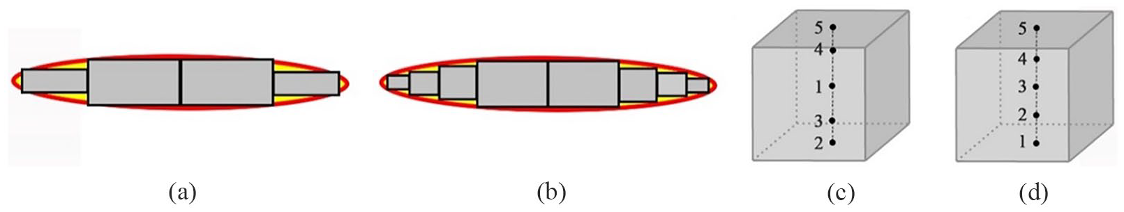
Discretisation of a yarn cross section using (a) four and (b) eight shell elements with uniform nodal thickness (Ha-Minh et al., 2013) and the location of through-thickness integration points in LS-DYNA according to different quadrature rules (c) Gauss and (d) Trapezoidal.
Different approaches to modelling fabrics: meso-scale modelling using (a) shell elements and (b) solid elements.
Shockey et al. (1999) created a comprehensive finite element model using solid elements for a plain-woven fabric using data and observations from laboratory tests. Individual yarns were modelled discretely and considered as a continuum in this model (as shown in Figure 6(b)). Two separate models were created in their study, with two different levels of detailing in the models. The more detailed model was implemented using solid elements and was meant to be utilised in capturing the underlying dynamics of fabrics upon impact. This includes detailed modelling of the interaction between yarns, contact between the fabric and the projectile and its fragments. The objective of this study was to model explicitly the failure mechanism of yarns and fabrics in order to establish better design approaches. A simpler model with comparatively fewer details was also implemented using shell elements for fragment barrier design. Explicit modelling of orthogonally assembled warp and weft yarn sets provided the capacity to quantitatively analyse inter-yarn friction by introducing frictional coefficients in the detailed model. The UMAT in LS-DYNA was employed in both models. Duan et al. (2005a, 2005b) used a similar model to investigate the role of friction during ballistic impact. Continuum yarns in this model were meshed using eight-node solid elements and 12 elements per lenticular yarn cross section. The level of numerical detail was facilitated with the proper definition of contact between yarns using a surface-to-surface contact algorithm. The model, however, uses identical yarn cross sections, both across the warp and weft. Yarn cross sections across the warp and weft may be different, even for fabrics with the same warp and pick densities. The geometry of the fabric can often be modelled by sweeping a yarn cross section along a sinusoidal centreline path in the form of equation (1), representing the centreline trajectory of an undulated yarn, where t and s represent yarn thickness and span, respectively
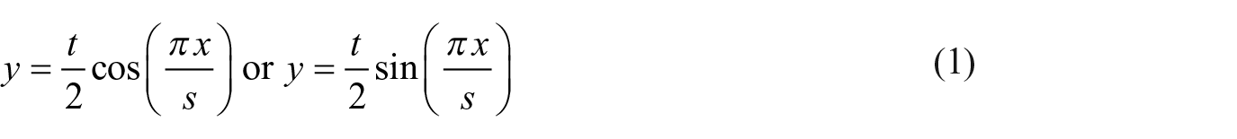
This can be graphically illustrated as shown in Figure 6. Sweeping a yarn cross section along a sinusoidal centreline, as shown in Figure 6(a), multiple times will yield a 3D repeat unit of a woven fabric, as shown in Figure 6(b).
(a) Sweeping a yarn cross section along a sinusoidal centreline to generate a yarn and (b) cross-section of the repeat unit obtained by multiple sweeps.
The numerical model used by Shockey et al. (2001) was made up of 25 yarns with a plan area of approximately 21 mm × 21 mm, meshed with 100,000 elements having 200,000 nodes and took 24 h to run on a Silicon Graphics Incorporated (SGI) Octane workstation with a single CPU using LS-DYNA. The baseline fabric model of (Yang et al., 2018) represented a plan area of 120 mm × 120 mm. The fabric was meshed with 12 solid elements per yarn cross section using LS-DYNA. This simulation took 30 h to run on a seven-core Intel® Core TM i7-2660 CPU 3.4 GHz processor with 8 GB of system memory. With the increase in computational power, researchers have begun using meso-scale modelling where yarns are modelled as 3D continua meshed using solid elements (Chu et al., 2017; Duan et al., 2005a, 2006a, 2006b; Zhang et al., 2008). Although it is common to use shell elements instead of solid elements to mesh woven geometries in order to save computational time, it lacks accuracy in comparison with using solid elements (Barauskas and Abraitiene, 2007; Gürgen, 2018).
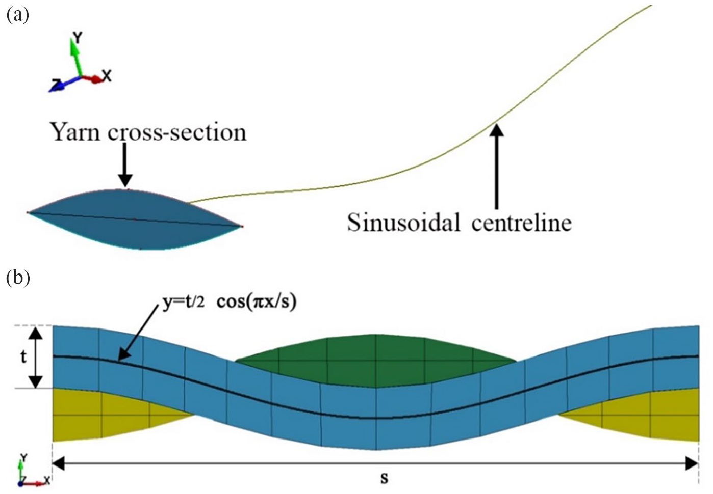
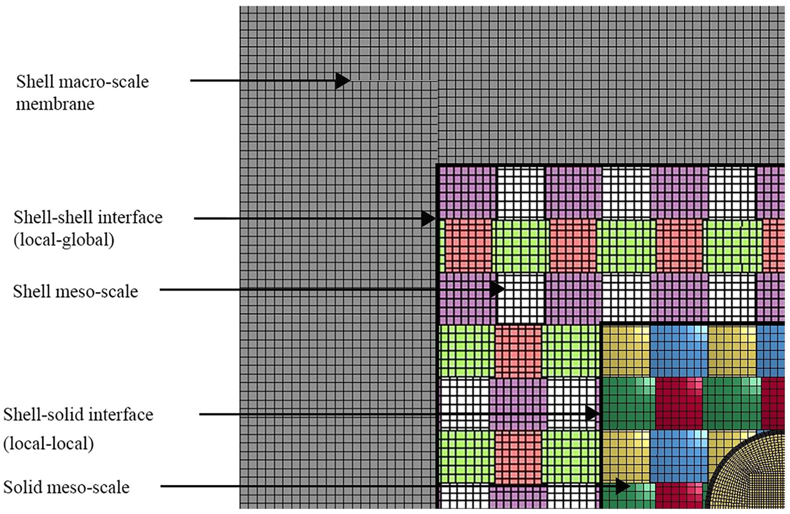
Another technique is to use the multi-scale modelling approach of the fabric down to the meso-scale (explicit modelling of yarns using either shell or solid elements) close to the impact region, and macro-scale (fabric treated as an isotropic membrane) architecture for regions decidedly away from the impact point such that the modelling resolution or the computational expense of the fabric is decreased with distance from the impact point. Solid elements, capable of capturing thickness changes upon transverse impact, can be used at the impact region, while shell elements can be used immediately next to the solid elements which are able to capture tensile deformations, therefore being more computationally efficient than using solid elements continuously. Using solid elements capable of tracking thickness changes is more important at the impact region since projectiles apply extreme transverse compressions in that locality. Even though two element types have been used in the design, the resolution of modelling remains the same at the meso-scale (homogenised yarn level). This approach of using different element types in the same model has been termed ‘hybrid element analysis’. Further away from the impact region, less fine resolution can be implemented by adopting a homogenised membrane using shell elements. This approach shows a noticeable improvement in computational efficiency. Nilakantan et al. (2010) simulated a fabric of plan area 102 mm × 51 mm using LS-DYNA on a 64-bit Dell Precision 690 workstation with four Intel Xeon 3.00 GHz processors and 16 GB RAM. A 50% reduction in simulation runtime was observed as well as a 40% reduction in memory requirement. Barauskas and Abraitiene (2007) also used a hybrid meso- and macro-level modelling approach to simulate impact on fabrics. For the meso-scale model in the impact region, thin shell elements were used to model yarns, and for the macro-scale model, away from the impact region, roughly meshed uniform orthotropic thin shells were used. However, their model suffered from an inability to track through-thickness dimension changes in the yarns. Using different resolutions in the same model is also known as multi-scale modelling or global-local modelling. In global-local modelling, homogenised membrane fabric is considered global, while the meso-scale fabric is considered local in the same model. Analogously, a hypothetical micro-scale fabric can be considered as local while a meso-scale fabric can be considered global in the same model. At the transition from higher to lower resolutions, local–global interfaces are created. At these interfaces, the resolution of the fabric changes from a high resolution to a lower resolution, which can be micro-scale to meso-scale or meso-scale to macro-scale. Some of these resolutions and interfaces are graphically illustrated in Figure 7. However, in hybrid element analysis, different element types are used while modelling in different resolutions, whereas multi-scale/global-local modelling may use the same element type. A general representation of a cross section is illustrated in Figure 8(b). This concept is used by numerous researchers in a similar manner to save computational time in comparison with purely solid element models (Ha-Minh et al., 2011; Jia et al., 2013; Rao et al., 2009b). The same concept is valid for future developments, such as global-local modelling of fabrics using solid element-discretised homogenised yarns away from the impact zone and higher resolution modelling (filament level or higher) at the impact region. Constituent filaments modelled explicitly in a yarn could represent filament spreading under a projectile, inter-filament interactions and fibrillation failure of filaments. This level of modelling remains a distinct possibility with increasing computational power at disposal. Analogously, a hybrid-mesh modelling technique has also been reported recently, where a meso-scale fabric model was constructed by interlacing yarns of different mesh densities (i.e. 2, 4, 6, 8 and 12 elements per yarn cross section). Significant reduction in computation costs in terms of elements, memory and required solving time has been achieved in comparison with the traditional, meso-scale model (Yang et al., 2018).
Multi-scale modelling of a fabric with different resolutions embedded in the same model and local–local and local–global interfaces present.
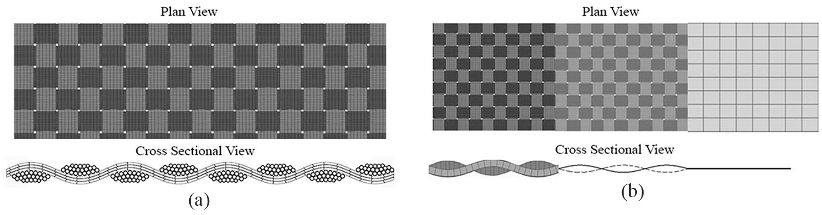
Different approaches to modelling fabrics: (a) micro-scale modelling using solid elements and (b) multi-scale modelling using different element types and resolutions.
Taking a step beyond meso-scale modelling, Grujicic et al. (2017) reached the fibre/filament level/micro-scale modelling of a fabric. However, the modelled fabric consists of only eight yarns (five and three in warp and weft directions, respectively) to minimise the computational time. Each yarn in the model consists of 37 individual, parallel filaments, with an average diameter of 2 μm, each of which is treated as a continuum Lagrangian object. Each yarn was discretised using approximately 2500 eight-node, first-order, reduced integration, continuum Lagrangian-type elements with an average edge length of approximately 1 μm. The meshed object depicting yarns at a crossover is illustrated in Figure 8(a). A detailed representation of a fabric such as this can account for deformation phenomena such as fraying and fibrillation in contrast to less detailed models. It could also represent interactions among fibres, which was impossible in the previous homogenised yarn (meso-scale) models. Even though extremely detailed, application of this model for a fabric swatch large enough for modelling ballistic impact can be highly resource-intensive in terms of computational power. On a 12-core, 3.0 GHz machine with 12 GB of memory, this simulation on ABAQUS/Explicit took 50 min to run. Moreover, commercially available ballistic fabrics such as Kevlar S706 woven using KM2 yarns have 400 filaments in a yarn cross section, whereas this model contains only 37 fibres. However, this is a step forward and can be considered as state-of-the-art fabric modelling currently available. Recently, Kevlar single filaments (KM2) have been modelled down to the fibril level by Staniszewski et al. (2018). However, in reality, a single yarn consists of hundreds of filaments which would make it extremely computationally expensive to model a fabric swatch in this resolution. In the future, modelling a fabric in such a high resolution in the fibril level will be computationally affordable with the aid of HPC facilities and parallelised finite element codes.
Computational analysis of the ballistic impact on dry woven fabrics has progressed over many years using different approaches, as summarised above. Starting from pin-jointed bar elements, membranes, meso-scale modelling using shell elements, to using solid elements and combinations thereof as a compromise between realistic modelling and computational expense, it has now come to filament-level modelling. However, simulation of a full-blown model including details to the filament-level for a large fabric swatch subjected to impact loading may still be debatable in terms of computational expense. The choice of modelling resolution depends on the purpose of the carried-out research and the analyst’s requirement. The current state-of-the-art in modelling ballistic impact remains at meso-scale modelling using solid elements. This section merely covers some of the highlights in the said evolution process. It is clear that the modelling a fabric material with reasonable accuracy is challenging. Adding STF into the structure makes it even more so. The following section discusses different approaches to incorporating the effect of STF impregnation to a fabric model.
Incorporation of the effects of STF in the modelling of fabrics
Even though research on ballistic impact on dry woven fabrics has seen consistent progress in the past two decades, the same cannot be said for STF-impregnated fabrics, regardless of their noteworthy performance in impact resistance in comparison with dry fabrics. As laid out in section ‘Various approaches to numerical modelling of fabrics’, computational modelling of dry fabrics itself is a challenging task and STF impregnation makes it even more challenging and computationally more expensive. Even though STF impregnation for elevated impact resistance started gaining traction more than 15 years ago, limiting modelling and computational power may have slowed growth in computational studies on STF-impregnated fabrics. Nevertheless, with the improvement of computational power and availability of better materials in the market, there is an opportunity to elucidate the underlying dynamics of ballistic impact on STF-impregnated woven composites, in terms of energy absorption, failure determination and prediction and shear thickening behaviour. Only a very limited amount of research is reported in publicly available literature. STF modelling approaches without fabric modelling are also discussed in the present work with suggestions to incorporate them in STF–fabric composite models. Empirical studies seem to have gained traction already, but computational analyses show slower development in modelling STF-impregnated fabrics. The following discussion analyses critically the work done on simulating STF and STF-impregnated fabric behaviour, summarises the approaches used and proposes a novel approach of modelling STF-impregnated fabric in conclusion compromising on reliability and computational expense.
Approaches to numerical modelling of STF-impregnated fabrics
Rabb and Fahrenthold (2011a, 2011b) claim to have developed the first general computational model for STF-impregnated fabrics that is capable of representing inertial, thermodynamic, frictional and viscous effects. The work done by Rabb and Fahrenthold (2011a, 2011b) was a further development of the work done by Shivarama and Fahrenthold (2004) for dry fabrics. The original hybrid-particle-element (HPE) method was modified in this study using an equation of state (EOS) and a generalised Bingham fluid model (Shivarama and Fahrenthold, 2004) to account for STF effects. The HPE method is based on a combined particle-element kinematic scheme, in which particles are used to represent all inertia, thermodynamics of compressed states and contact effects. Furthermore, finite elements are used to model tension and elastic–plastic shear. Thermodynamic effects of STF-impregnated fabric are embodied by introducing EOS for the fabric particles. Assuming viscosity and friction to be the main modes of energy dissipation, a generalised Bingham fluid model was used for the particles to represent energy dissipation effects. It has been concluded by Rabb and Fahrenthold (2011a, 2011b) that STF-treated fabrics are incompetent to be used effectively as fabric barriers in fan blade containment systems and are less likely to prove themselves useful in soft armour systems. Wetzel and Wagner (2012), however, in a technical comment paper, argued that the conclusion in the work done by Rabb and Fahrenthold (2011a, 2011b) was ‘premature and unsupported’.
Another popular approach in the literature is to incorporate experimental/simulation results of yarn pull-out tests to account for the effect of STF impregnation of a fabric. As evident from this modelling approach, the governing assumption of this type of STF-impregnated fabric simulation is that frictional interaction is the dominant contribution from intercalated STF in fabrics. However, it has not been proven that enhanced frictional interaction is the sole contributor for the enhanced performance of STF-impregnated fabrics. Lee and Kim (2012) used LS-DYNA to simulate ballistic impact on an STF-impregnated fabric using this approach. MAT 2 (orthotropic elastic material) was used to represent the constitutive bahaviour of Kevlar (Cheng et al., 2005). A von Mises stress–based failure criterion was introduced to this meso-scale, shell-based finite element model. Assuming frictional enhancement as the dominant contribution of STF impregnation, an additional phase does not need to be accommodated in this fabric model in order to model the STF explicitly. Modifications of friction between the constituents are used instead. Therefore, this model resembles a dry woven fabric in appearance, although different frictional properties are used. The yarn pull-out test was simulated repeatedly to match the experimental STF–Kevlar yarn pull-out test data from reference (Lee et al., 2009), by changing the variables in the friction smoothing algorithm used in the LS-DYNA code, as in equation (2).

where µ, µs, µd, c and v denote the coefficient of friction (at time t), the static coefficient of friction, the dynamic frictional coefficient, exponential decay coefficient and the relative velocity of the considered surfaces, respectively (Hallquist, 2006). While the Coulombic description of friction is used, equation (2) smoothens the transitions from static to kinetic friction.
Figure 9 illustrates graphically the yarn pull-out test simulation. To represent the enhanced frictional effect of STF impregnation, a user-defined friction subroutine was employed in this study, where an onset of abrupt frictional coefficient was observed at 23.3 mm/s pull-out speed (crosshead speed). This threshold speed is, however, debatable in terms of practical applicability since the deformation under the mentioned speed can be considered as quasi-static in comparison with strain rates generated upon ballistic tests. The same STF-impregnated model was used to study high-velocity impact of STF-impregnated Kevlar fabric targets by Park et al. (2015). Several simulations with multiple fabric layers, treated and untreated, were carried out. Subsequently, they were compared with the experimental results obtained by Kevlar fabrics impacted using a light gas gun. Targets were impacted using 5.56-mm-diameter 2017-T4 aluminum spheres with velocities ranging from 1000 to 2000 m/s. Four different fabric compositions were tested: single layer treated/untreated, eight layers untreated and five layers treated. Even though visually similar results were observed, highly contradicting energy absorption trends were reported between the experimental and numerical results for each test setup. For the single-layer setup, even though the experimental results exhibited an exponential increase in absorbed energy with increasing velocity, both the models (treated and untreated) showed a decrease in energy absorption at higher velocities. For both of the multi-layered targets, the simulations largely overestimated the energy absorption from 1000 to 1400 m/s. Both of the models exhibited a constant amount of energy absorbed after 1200 m/s. Assuming the effect of STF impregnation to be solely frictional may, therefore, be unable to fully capture the dynamics of ballistic impact on STF-impregnated fabrics.
Friction modelling based on a yarn pull-out test: numerical simulation of yarn pull-out from an STF-impregnated fabric.
Hasanzadeh et al. (2017) and Mirrahimi et al. (2017) later used the same approach in their exercises to study the response of STF-treated high-modulus poly-propylene (HMPP) fabric composites undergoing ballistic impact, using LS-DYNA. However, eight-node solid elements were used to simulate the woven fabric in contrast to the original study which used shell elements (Lee and Kim, 2012). Yarn pull-out was empirically studied at a pull-out/crosshead speed of 1.67 mm/s to observe frictional effects. As opposed to the original study by Lee and Kim (2012), in which the shear thickening property in the impregnated fabric was claimed to be invoked at 23.3 mm/s, the pull-out speeds used by Hasanzadeh et al. (2017) were considerably less. The STF in both the studies was fumed silica suspensions in PEG with a molecular weight of 200 g/mol; however, the particle sizes were 100–500 nm (Lee et al., 2009) and 12 nm (Hasanzadeh et al., 2015), respectively. Furthermore, the fabrics used in the two studies were different. Lee and Kim (2012) used Kevlar fabric made of KM2 yarns, while Hasanzadeh et al. (2017) used HMPP fabrics. These reasons are likely to cause a difference in the shear thickening behaviour of the two systems. Moreover, there is no information available on the user-defined friction subroutines used in the simulations by Hasanzadeh et al. (2017), even though they claim that simple Coulomb friction was introduced and modified to account for the shear thickening effect. Kordani et al. (2016) also approached the problem using the same method as Hasanzadeh et al. (2017), but with modifications made on the parameters used for static friction coefficient, dynamic frictional coefficient and exponential decay constant in the contact algorithm used to represent the interaction between yarns. Khodadadi et al. (2018), in a recent study, used the same approach as Kordani et al. (2016) but used alternative values for static and dynamic frictional coefficients. The speed of yarn pull-out has not been reported and the difference in speed of pull-out is likely to have caused such a drastic difference in the coefficients between the two studies. The difference in areal densities of the fabric used (even though it was the same Kevlar material) and the difference in silica particle sizes used could have been contributing factors for the contrasting results.
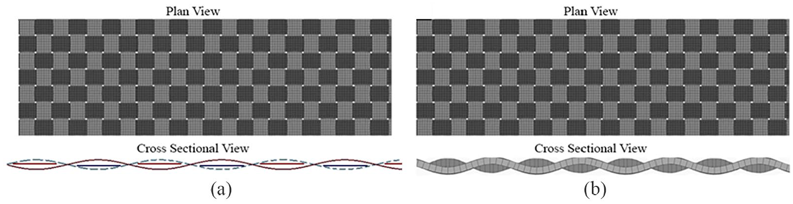
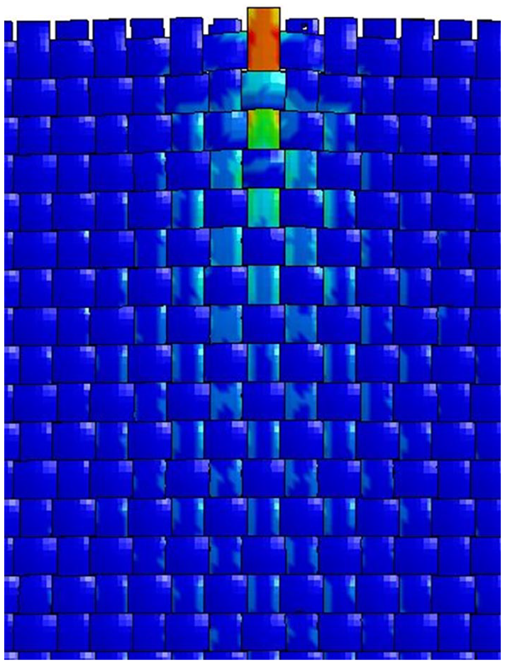
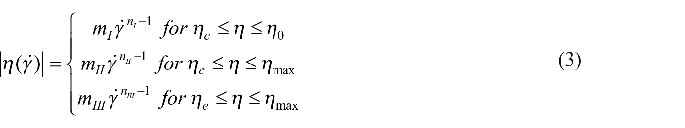
Lu et al. (2014) report the numerical simulation of STF-impregnated warp-knitted spacer fabric under impact loading. Even though the scope of this work was limited to woven fabrics and the impact velocities employed were very low, the modelling approach of STF is noteworthy. A piecewise definition for apparent viscosity, as defined by equation (3), was introduced to account for three different zones (shear thinning, Newtonian and shear thickening). These zones are illustrated in Figure 10(b). A user-defined subroutine VUSDFLD in ABAQUS commercial finite element code was used to incorporate the viscosity model in the analysis. In the composite model of the spacer knit and STF, the STF was considered as a viscous fluid able to flow upon impact loading and was modelled as an Eulerian part. This approach of explicit modelling STF can be embedded into prevailing dry fabric models along with suitable contact algorithms and STF viscous properties. The composite model is illustrated in Figure 10(a).
where η,
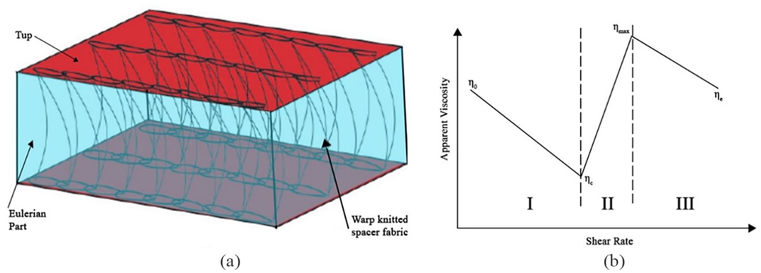
(a) Piecewise definition for apparent viscosity and (b) the composite model developed by Lu et al. (2014).
Mossakovsky et al. (2010) and Lomakin et al. (2011) studied ballistic impact on a titanium plate backed by Kevlar fabric layers, neat and STF-impregnated. The study consisted of both experiments and nonlinear simulations carried out using the LS-DYNA code. Similar to the dry fabric models discussed in previous sections, this exercise assumed isotropy in Kevlar plies and modelled them as isotropic elastic membranes. Fracture was modelled using an automatic element erosion algorithm using the failure strain of a Kevlar yarn. Contact friction was introduced between the Kevlar plies, projectile and STF using the well-known Coulomb friction model. STF was introduced as a fluid assuming Eulerian formulation for elements (materials are allowed to flow across element boundaries in a rigid mesh). A series of dynamic tests were performed using the Split Hopkinson Pressure Bar (SHPB) method to develop a simplified mathematical model of the STF, which was represented as a Newtonian fluid in a restricted strain rate range. The stress–strain behaviour of STF was captured using SHPB, which was apparent to be strain rate independent. Moreover, the stress–strain curves were approximated by a quadratic function. Strain rates considered in the study varied from approximately 200/s to 2500/s. Asija et al. (2017) later report stress–strain behaviour of a different STF, using strain rates up to 21,200/s which have a similar material response. Both of these studies suggested a sharp reduction of stress after the peak stress. However, Fu et al. (2018) report the behaviour of another STF which did not have a reduction of stress as strain increased. The curves exhibited the characteristic hyperelastic behaviour as strain rate was increased.
The works done by Mossakovsky et al. (2010) and Lomakin et al. (2011) were not entirely focused on the ballistic impact on STF-impregnated fabrics; instead, the STF-impregnated fabrics were coupled with metallic plates. The applicability of isotropic membranous assumption of Kevlar fabrics and definition of failure criteria are debatable in their work, even though the model accounted for inter-ply friction. This approach can still be used as a precursor to develop a more comprehensive model, dedicated to STF-impregnated fabric systems. However, having to use different domains such as continuum Lagrangian for the projectile and fabric while using discrete particles (such as smoothed particle hydrodynamics (SPH) in LS-DYNA), and/or Eulerian or Arbitrary Lagrangian-Eulerian (ALE) domains to represent the STF can be challenging and will be further discussed.
Valizadeh et al. (2008) developed an analytical model which can determine the yarn pull-out force in plain-woven fabrics based on a force-balance analysis. Moreover, this model predicts important mechanical parameters such as weave angle variations, inter-yarn frictional coefficient, normal loads at crossovers, lateral forces, and opposed yarn strain within the fabric. The weave angle can be defined as the angle of the yarn axis to the plane of the fabric. The frictional coefficient between yarns is estimated by equation (4)
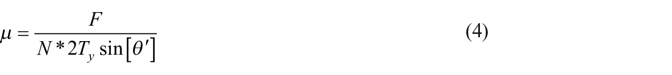
where µ, F, N, Ty and

where θ and α represent the weave angle before pulling and the fabric deformation angle, respectively. These variables are graphically illustrated in Figure 11.
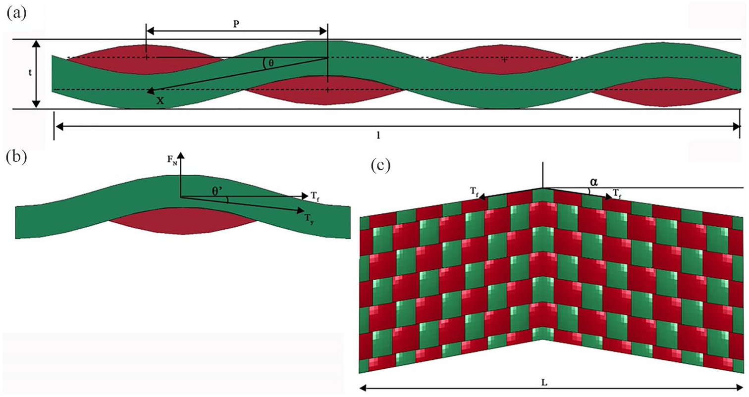
Graphical illustration of yarn pull-out (c) and associated variables (a), (b), and (c).
This model assumes that the denominator of equation (4) is equal to the transverse force of the fabric and is dependent solely on fabric geometry-specific parameters. Therefore, the frictional coefficient is independent of the material and fibre/yarn surface properties. In general, the static frictional coefficient is largely governed by the surface topology/roughness of the yarns, while the dynamic counterpart is mainly controlled by the constituent material (Grujicic et al., 2017). Therefore, equation (2) may be a better approach than equation (4) for practical applications.
However, Alikarami et al. (2016), in a later study, used this analytical model to estimate the coefficient of friction between yarns in an STF-impregnated woven fabric. They further studied the effect of yarn pull-out velocity of STF-impregnated Kevlar on the frictional coefficient. Yarn pull-out tests were carried out at 0.83, 4.17 and 8.33 mm/s, respectively. However, the results exhibited a decrease in the coefficient of friction with increasing pull-out speed. Alikarami et al. (2016) justified this unanticipated decrease in the frictional coefficient by claiming that the above-mentioned pull-out speeds were located in the shear thinning region. The low velocity used is unlikely to have exceeded the critical shear rate necessary to invoke shear thickening. However, this complements the intriguing notion that the effect of STF impregnation on woven fabrics may not be only the frictional enhancement between constituent yarns. As discussed above, the conclusion drawn by Park et al. (2015) that assuming a friction-dominant energy absorption model may not be ideal supports this claim. However, further research in terms of advanced models encompassing the STF effect is necessary to validate this concept. Consequently, modelling exercises should further focus on explicit modelling of the STF domain.
Grujicic et al. (2017) developed a computational framework for the simulation of a yarn pull-out test applicable for STF-impregnated Kevlar KM2 fabrics using ABAQUS FEM code. The model used was of high resolution and was beyond the meso-scale (yarn-level), with each yarn containing 37 parallel fibres modelled explicitly, as described in section ‘Various approaches to numerical modelling of fabrics’. Even though this simulation concentrated purely on the yarn pull-out test, the modelling approach employed is noteworthy. Moreover, similar models may be used for ballistic impact simulations for better elucidation of the underlying dynamics of ballistic impact which have not yet been comprehended. The fibre-level modelling allowed the definition of failure mechanisms such as fibre fibrillation and fraying, which would otherwise be impossible. Neat, carrier liquid–impregnated and STF-impregnated fabrics were simulated in the exercise. A combined continuum Lagrangian/discrete-particle formulation approach was used to model the STF-impregnated fabric. The STF has been represented as an assembly of discrete, interacting particles interconnected by ‘connector elements’ that could simulate the rheological behaviour of STFs. The fabric embedded in the STF is illustrated in Figure 12(a), along with an illustration of the presence of filaments in yarn cross sections in Figure 12(b).
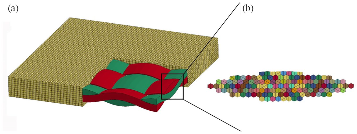
Illustration of (a) model of the fabric embedded in STF and (b) filaments in the yarn cross sections.
The governing mass, momentum and energy conservation equations are solved with a second-order explicit analysis, with a model combining finite elements and discrete-particle algorithms as described in Grujicic and co-workers’ preceding research (Grujicic et al., 2014, 2015; Grujicic and Snipes, 2013). The rheological properties of the STF were controlled by the stiffness of the connecting elements which were determined by a parametric study. Consequently, a liquid phase for the carrier liquid was not explicitly modelled. Moreover, while the contact between the particles was defined, the particle–fibre contact is unclear. Since a mesh-based penalty contact formulation is difficult to be implemented on a model of this nature where fibres contain hexahedral Lagrangian elements and discrete element method (DEM)-based particles, the contact definition will be complex. However, nonlinear finite element codes such as LS-DYNA support contact between Lagrangian and Eulerian elements by the *CONSTRAINED_LAGRANGE_IN_SOLID keyword, including friction, directional effects and different coupling algorithms (LSTC, 2019). However, this approach of modelling STF needs further developments to study the rate-dependent STF behaviour.
Bennett et al. (2018) propose a method to model the behaviour of STFs using the DEM using the commercial multiphysics software package Simcenter STAR-CCM+. The study concerns the viability of using STF as a damping mechanism in multi-layered plate arrangements under impulsive loadings. However, the multi-scale modelling approach is noteworthy for STF-impregnated fabric modelling, in the sense that the approach has the potential to be used for explicit modelling of the STF domain in an STF–fabric composite. The biphasic STF was modelled with an explicit fluid phase (Eulerian) and an explicit particle phase (DEM). The traditional finite volume computational fluid dynamics (CFD) was used to model the fluid; the particle phase was coupled with the fluid through drag and lubrication forces. The material response is, therefore, captured more comprehensively than in the simplified approaches used by Mossakovsky et al. (2010), Lomakin et al. (2011) and Lu et al. (2014). However, the major drawbacks of the modelling approach proposed by Bennett et al. (2018) are the complexity of the model and the extreme computational expense incurred. Using DEM is generally computationally more expensive than Lagrangian hexahedral elements and HPC facilities had to be used due to the high computational expense. However, this approach of multi-scale modelling of the STF holds potential to further study the behaviour of STF and, especially, MSTF, since this approach allows the definition of explicit contact between particles and particles and the carrier fluid. However, the additional advantage comes with the added expense of being computationally expensive.
Micro-scale modelling of STF has also been reported in the literature (Chauhan et al., 2018). Chauhan et al. (2018) used Lagrangian approach for the solid phase of STF, while Eulerian approach was used to model the carrier liquid. This approach of modelling STF is unsuitable for STF-impregnated fabric modelling due to the very high number of elements that have to be used. Meso-scale fabric numerical models themselves are computationally expensive. Adding a much higher number of elements using this approach for the STF will be impracticable in a computational time point of view. However, the same approach is useful to further study the mechanism of shear thickening.
Krayterman and Malone (2018) developed two models for a rate-activated tether which employs STF using LS-DYNA. The first approach used *MAT_PLASTICITY_POLYMER (MAT 89) keyword in LS-DYNA to account for the strain rate sensitivity of STF. This LS-DYNA material card allows the definition of an elasto-plastic material with an arbitrary stress–strain curve and arbitrary strain rate dependency, including rate dependency of failure strain (LSTC, 2018b). Krayterman and Malone (2018) used a series of stress–strain curves input to the material card as tables, each table corresponding to a different strain rate. The original experimental force–time/force–displacement curves from tether experiments were converted to stress–strain curves for this purpose. However, this experimental method was focused on modelling the overall behaviour of the tether and not for STF alone. Moreover, the maximum tension rate in the study is 0.167 m/s, which is well below the anticipated rates in a ballistic event. Higher rate testing is required for this method to be used in the context of interest of the present work. Nevertheless, this approach suggests the possibility of using a homogenised model for STF–fabric composites. Here, the fabric can be modelled at the homogenised yarn (meso-scale) resolution without an explicit STF domain. The experimental stress–strain curves at different strains of STF-impregnated yarns have to be used instead of neat yarns. There have been no reports on using such an approach for STF–fabric composites to date and this could be study worthy.
The second approach proposed by Krayterman and Malone (2018) is more simplified and computationally inexpensive than the above-mentioned first approach. In an effort to employ simple 1D elements such as springs which use force-deflection data as input for the material model, added programming functions to the LS-DYNA keyword file were used instead of complex user-defined material models. In this case, the tether was considered to be a homogenised material, and consequently the STF was not modelled explicitly. The functions used were implemented using the keyword *DEFINE_CURVE_FUNCTION in LS-DYNA which allows the real-time extraction of data such as displacements, velocities, accelerations, stresses, forces and moments from the simulation. The mechanical response of the tether is captured using five different such functions. However, the modelling approach is fairly complicated and demands additional modelling skills and an external compiler for the LS-DYNA code to be implemented. Especially, this approach is unsuitable for a complicated geometrical problem such as an STF–fabric composite. The implementation of frictional or failure contact using this method will be difficult if not impossible due to non-conformal meshes of the fabrics and STF among other factors and is further discussed below.
Lim et al. (2006) pioneered the expansion of range of available rheological data of STF from rotational viscometers. The high-strain-rate compressive responses of STF were analysed using a modified SHPB test setup (Lim et al., 2008, 2009, 2010a, 2010b). A dynamic squeeze flow is created thus inducing shear to the STF specimens with strain rates well above those possible in traditional rotational viscometers. The strain rates considered in these studies are much higher than encountered in previous research available and are in the order of actual ballistic impact events. Moreover, Lim et al. (2010b) report that the fluid–solid transition is not triggered by a critical shear rate and that a critical shear strain is needed. The method used is different from Mossakovsky et al. (2010) and Lomakin et al. (2011) and reports a more detailed analysis and subsequent constitutive modelling using a phenomenological rate-sensitive model (Lim et al., 2011). However, this model could only predict the STF behaviour within the range of strain rates where the experimental data were already available. This is due to the phenomenological nature of the model proposed
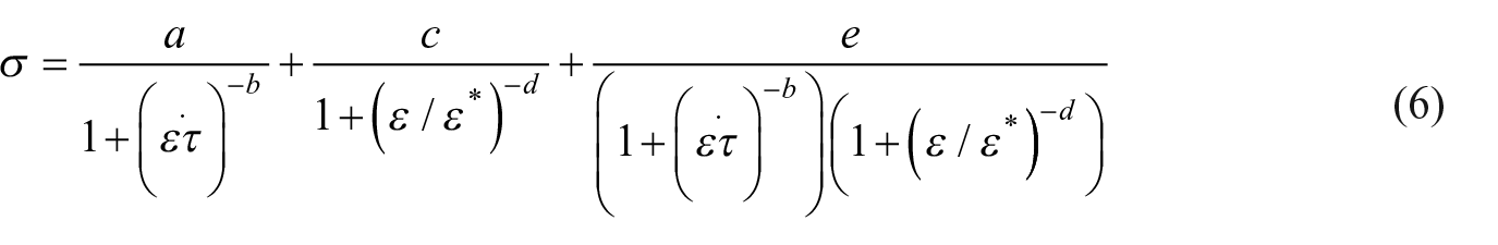
Equation 6 denotes the phenomenological model developed (Lim et al., 2011). The model constants were determined using the loading portions of the three-dimensional stress–strain–strain rate plots using a surface fitting approach.
Fu et al. (2018) used the same approach to study the behaviour of STF where the advanced rate-dependent Johnson-Cook (1995) constitutive model was employed to constitutively model its behaviour. The rate-dependent model constants were derived from the experimental data (surface fitting to stress–strain–strain rate plots) which permits the material model to be easily used in commercially available finite element codes. This approach of modelling can be adapted to STF-impregnated fabrics. However, this essentially means that the STF intercalated in the fabric must be modelled explicitly to be able to assign a different model from the fabric. This gives rise to the complication of generating a mesh for the STF intercalated in the fabric. The complication is due to the intricate geometry of a meso-scale fabric model. It is difficult to generate such a Lagrangian mesh keeping the computational expense reasonable. The element size of such a mesh will have to be extremely small compared to elements in the fabric mesh. This is graphically illustrated in Figure 13. The other alternative of using tetrahedral elements rather than hexahedral elements as shown in Figure 13 may yield a better mesh in terms of avoiding crossover voids. However, it cannot address the miniature voids present between yarns and the computational expense will be higher because of the element formulation and the higher number of elements in comparison with hexahedral elements. This is a considerable drawback given that the model is to simulate significantly large-sized fabric swatches undergoing ballistic impact, which will demand extremely high and impracticable computational expenses. Therefore, such models are not available in the publicly available literature. Consequently, the current state of the art of modelling STF-impregnated fabrics has also come to a standstill at this level with this issue.
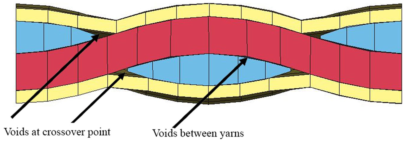
Illustration of a Lagrangian STF mesh encompassing the fabric mesh.
A myriad of approaches used to model STF/STF–fabric composites are summarised in Table 1 with the advantages and disadvantages considering the simulation of ballistic impact on an STF-impregnated fabric.
Different approaches of modelling STF/STF-impregnated fabrics and the proposed model.
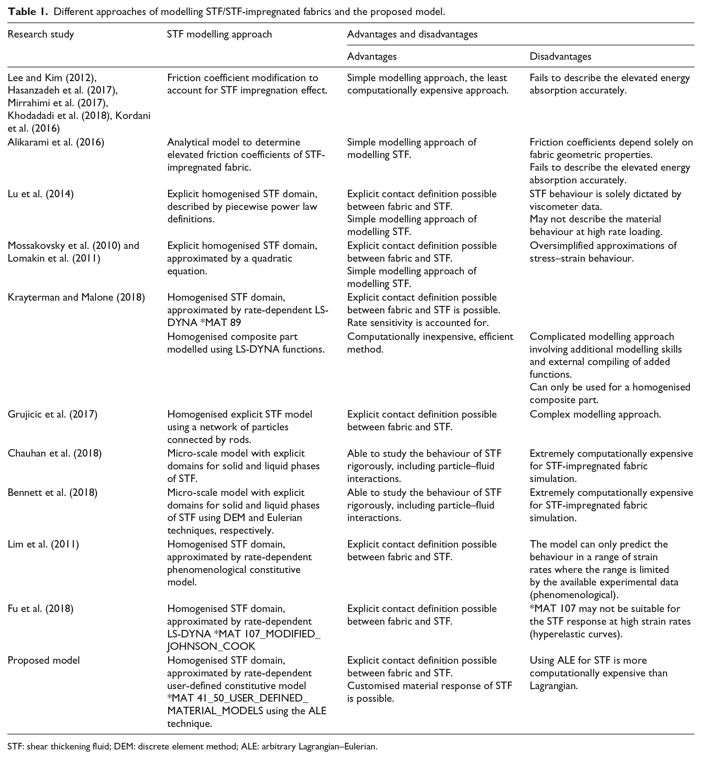
STF: shear thickening fluid; DEM: discrete element method; ALE: arbitrary Lagrangian–Eulerian.
As portrayed by the summary in Table 1, the state-of-the-art proposed solution should be a compromise between the computational expense and the accurate material response. Moreover, the above-mentioned inability to generate a conformal Lagrangian mesh with the fabric must also be addressed.
A novel framework to model STF-impregnated fabrics
Finite element mesh and contact definitions
A potential method of overcoming the drawbacks of the conventional Lagrangian element approach to model STF is the use of ALE approach. The ALE approach minimises the drawbacks of the two classical kinematical descriptions: Lagrangian and Eulerian (Donea et al., 2017). In the Lagrangian approach, nodes of the computational mesh move along with the material point. The main benefit of this approach is the ability to track free surfaces and interfaces between different materials with relative ease. On the other hand, the Eulerian description where the computational mesh is fixed in space and the material flows or moves through the grid and suitable for applications such as fluid dynamics. However, this requires precise interface definition and the resolution of flow details. ALE is a hybrid of these two kinematic descriptions where the nodes of the computational mesh are allowed to move with the material similar to Lagrangian approach or be fixed in space similar to the Eulerian description or move in an arbitrarily defined manner to yield continuous rezoning (Donea et al., 2017). The modelling of STF demands interaction of several materials in a single numerical problem. This includes solid yarns surrounded by thin layer/coating of STF. The accurate representation of behaviour of this thin coating is an essential part in obtaining a reliable result from numerical modelling of STF. Due to the constraints in conventional Lagrangian method in simulating the behaviour of such coating, the ALE approach is a suitable alternative to model the STF in an STF-impregnated fabric composite. Consequently, the ALE approach is used to model the behaviour of STF in this study.
The method proposed in this work uses a simple approach where a Eulerian domain encompasses the Lagrangian fabric mesh completely as illustrated in Figure 14. The volume in the Eulerian mesh which overlaps with the yarns is defined as a vacuum. This was done by defining a volumetric region by considering the yarns boundaries and subsequently filling it as a vacuum in the definition of ALE multi-material group (AMMG). The surrounding volume which represents the STF is created using the *INITIAL_VOLUME_FRACTION card.
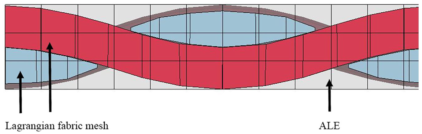
Lagrangian fabric mesh embedded in an ALE domain (STF).
Interaction between the Lagrangian fabric and the ALE domain is implemented via the *CONSTRAINED_LAGRANGE_IN_SOLID (CLIS) card. The penalty-based coupling method is selected via the parameter CTYPE in the *CLIS card. Friction between yarns and the surrounding fluid is also defined via CLIS.
Constitutive model for the STF Eulerian mesh
The Johnson–Cook material model or another suitable model can be defined for the surrounding ALE mesh which would replicate the behaviour of the STF. Analysis of the stress–strain response of STF obtained by Fu et al. (2018) suggests that a rate-dependent hyperelastic-type model may be more suitable than the used Johnson–Cook model. Mohotti et al. (2014) propose rate corrections to the widely used rate-independent hyperelastic material models such as Mooney–Rivlin constitutive model (Rivlin, 2006). This can be further extended to other Helmholtz free energy–based constitutive models such as Ogden (1984), Yeoh (1993) and eight-chain model (Bergström, 2015). More computationally inexpensive constitutive models such as the ZWT model (Xu et al., 2018) where the material Jacobian calculations are not required can also be used.
The stress–strain plots obtained by Lim et al. (2010b, 2011) show a different stress–strain response than Fu et al. (2018) indicating that the constitutive behaviour depends on the different STF materials. Therefore, creating a generalised constitutive model for all STF types may not be ideal. It must also be noted that the SHPB technique of characterising STF does not provide a constant strain rate experiment (Lim et al., 2010b) thereby making the constitutive modelling even more challenging. Moreover, user-defined material functions available in finite element codes such as LS-DYNA and ABAQUS must be used since many of these constitutive models are not readily available.
Preliminary simulations employing the proposed numerical framework
The ballistic impact simulation of an STF-impregnated Twaron CT716 fabric was simulated using the proposed numerical framework. A spherical projectile of 6 mm diameter impacting the fabric perpendicularly at 100 m/s is selected in this demonstration. As explained in section ‘Finite element mesh and contact definitions’, frictional contact between the fabric and the STF was defined as 0.4. The well-known Mooney–Rivlin constitutive model (LS-DYNA *MAT_27) was assigned for the STF. A transversely isotropic material model, ORTHOTROPIC_ELASTIC, was assigned to the fabric. The surrounding air domain was defined using *MAT_NULL card with supporting EOS. This initial setup is illustrated in Figure 15.
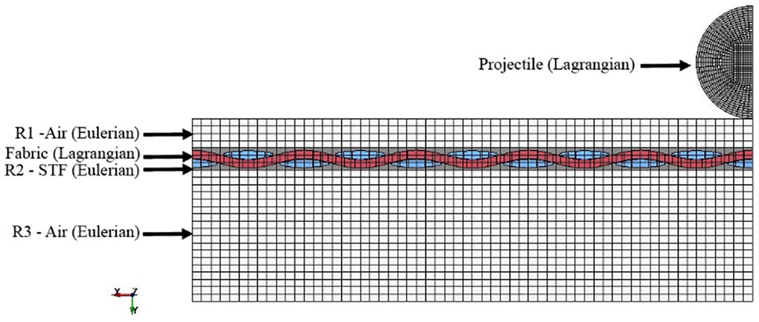
Illustration of the material definition.
Figure 16 shows an illustration of the simulation at 16 μs. Figure 16(a) shows the deformation of the Lagrangian fabric mesh and the Eulerian STF mesh deform together (Eulerian air mesh is hidden for clarity). Figure 16(b) shows a close-up view of the same with the mesh lines. It can be observed that the shape of the STF domain is retained and represented adequately by the Eulerian mesh.
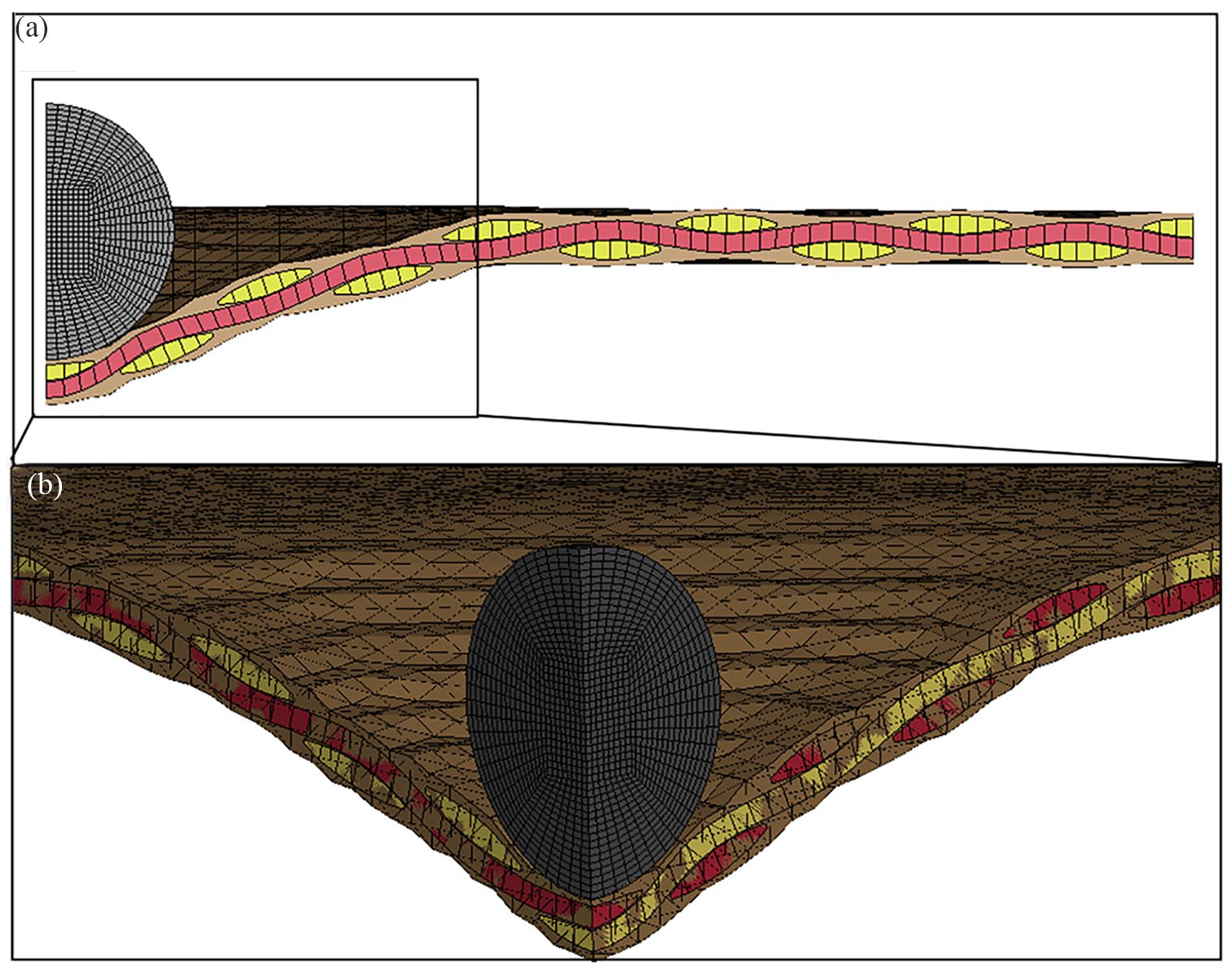
Deformation of the STF-impregnated fabric composite: (a) side view and (b) isometric view.
Moreover, Table 2 illustrates the transverse deformation profiles of the fabric and the STF layer. The characteristic pyramidal deformation discussed in section ‘Various approaches to numerical modelling of fabrics’ can be observed on both the fabric and the STF domain. Therefore, it can be concluded that the proposed method is demonstrating its ability to capture the behaviour of STF-impregnated fabric composites.
Transverse deformation profiles of the fabric and the STF.
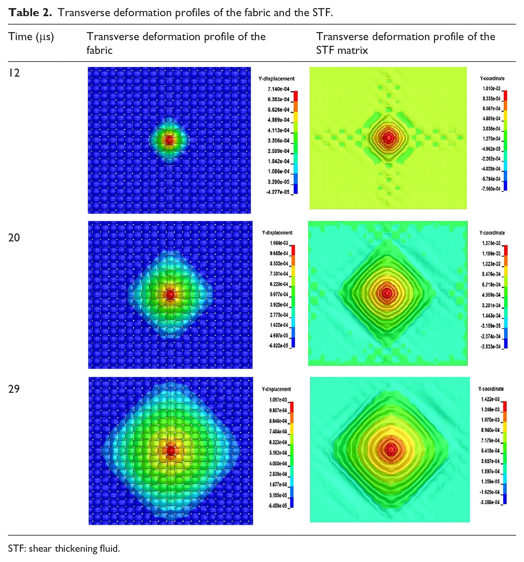
STF: shear thickening fluid.
More importantly, the proposed model is also able to capture the contribution of the STF domain to the energy absorption of the composite material. Figure 17 illustrates the internal energies of the warps (Figure 17(a)), wefts (Figure 17(b)) and the STF domain (Figure 17(c)). With a more detailed constitutive model for the STF as discussed in section ‘Constitutive model for the STF Eulerian mesh’, the proposed modelling approach will be able to quantitatively analyse the energy absorption behaviour of an STF-impregnated fabric composite.
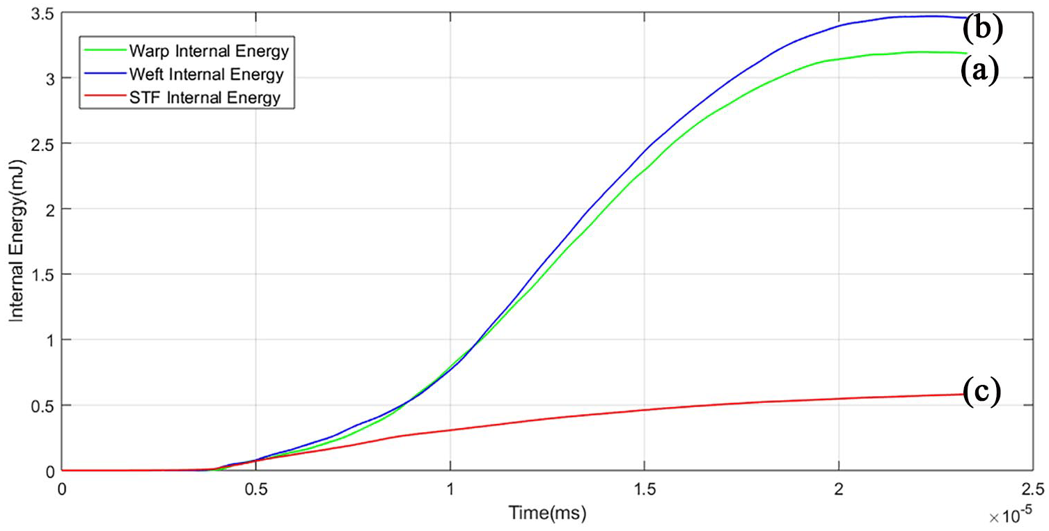
Internal energy of the (a) warps, (b) wefts and (c) STF during the simulation.
The approach of modelling proposed is an improvement from the current state of the art, in the sense that it could account for the energy dissipated by the STF alone and the varying strain rate effects while keeping the computational expense at a reasonable level. The proposed model can also be adapted to modelling other composite materials such as fabric–resin composites or hard armour panels.
In comparison with the reported work on modelling impact on dry fabrics, significantly fewer efforts have been informed in the case of STF-impregnated fabrics. The mechanism of shear thickening is complex, even though often considered as purely a frictional enhancement which certainly poses a challenge in numerical modelling. Various approaches have been used including explicit modelling of STF as an additional medium in the meso-scale level. However, lack of high strain rate data, in addition to the governing assumption that STF impregnation is purely a frictional enhancement, has resulted in slow progress in using STF-impregnated fabrics in ballistic mitigation applications. Material models such as *MAT_SPH_VISCOUS are available in commercial finite element packages such as LS_DYNA, explicitly meant for non-Newtonian fluids. However, the material model is unavailable for shell or solid elements but only applicable for SPH. Moreover, it is reported that the conventional apparent viscosity versus shear rate graph cannot replicate the STF behaviour at high strain rates (Fu et al., 2018). Contact cards defining interaction between SPH and Lagrangian elements are limited and therefore it is difficult to simulate the intricate contact behaviour between yarns and STF. However, it is possible to develop UMATs in commercial finite element packages such as LS-DYNA and ABAQUS, where the stress–strain behaviour of the material can be programmed by the user, generally using FORTRAN-based codes, implemented as subroutines for the main programme. This option provides the flexibility to incorporate customised constitutive equations governing stress–strain behaviour and optionally, failure in addition to the encoded model such as Johnson–Cook used by Fu et al. (2018). Many internal variables can be post-processed in UMATs using history variables that would otherwise be impossible to process. Therefore, UMATs are an attractive candidate for modelling the STF impregnation effects into woven fabrics. However, implementing a UMAT is complex and no previous research is available in the public literature in the same context.
Conclusion
This article provides a comprehensive summary of different approaches used in numerical modelling of STF-impregnated fabrics in ballistic mitigation and a novel approach of modelling such materials is proposed in conclusion. An overview of shear thickening behaviour of dense colloidal suspensions is provided to give readers a better understanding about the applications of STF in fabrics. The recent ‘contact rheology model’ has been discussed in addition to two other popular models, the order–disorder theory and hydrocluster formation theory. The contact rheology model provides a reasonable perspective to the abrupt and sometimes discontinuous jumps in apparent viscosities of dense colloids.
Impacts on dry fabrics and multiple-layer fabrics have been researched extensively for over 15 years, both empirically and computationally. Fabrics have been modelled using various approaches and resolutions, such as pin-jointed bar elements, membranes, homogenised yarn level and filament level. These models show different levels of capability in capturing intricate geometrical details, inter-layer friction, inter-yarn friction, through-thickness deformation and energy absorption. Filament-level/micro-scale modelling has been introduced recently and could yield more realistic results, even though it is still untested in large enough fabric swatches, mainly due to the high computational expense. The current state of the art remains at the homogenised yarn or meso-scale level using solid elements.
However, there is relatively less work done on STF-impregnated woven fabric composites, and even less research on computational analyses of such fabrics. A few computational approaches used in simulation of STF impregnation in fabrics have been reviewed in detail with their potential limitations and source references. One of the most popular approaches is to consider the effect of STF impregnation as a purely frictional enhancement and to modify meso-scale dry fabric contact algorithms with Coulombic friction description coefficients to incorporate it. However, this approach has failed to replicate the energy absorption behaviour of STF-impregnated fabrics. The current state of the art of STF-impregnated fabrics for ballistic impact simulations is, however, limited to this level. A novel approach of modelling STF-impregnated fabrics which is able to address the shortcomings of the current state of the art is proposed in conclusion of the preceding work. Constitutive modelling of the STF can be further improved using rate-dependent constitutive models already available.
Footnotes
Declaration of conflicting interests
The author(s) declared no potential conflicts of interest with respect to the research, authorship and/or publication of this article.
Funding
The author(s) received no financial support for the research, authorship and/or publication of this article.