
Abstract
This article proposes a bioinspired soft coil-wrap gripper (CWG) that achieves concurrent enhancements in load capacity and object adaptability through innovative biomimetic structural design. The gripper incorporates a dual-layer pneumatic architecture: The primary structure comprises an elongated pneumatic chamber with an elastic coating layer, facilitating adaptive contour wrapping around target objects through a biomimetic coiling mechanism. An auxiliary end pneumatic chamber amplifies localized pressure postwrapping, ensuring optimal contact interface and grasping stability. By engineering contact layers with differential friction coefficients (higher inner layer versus lower outer layer), the gripper initiates a frictional self-locking effect during the wrapping process, thereby substantially improving grasping robustness. Experimental validation demonstrates that under pneumatic pressures of 0.1 MPa, the CWG effectively manipulates irregular objects spanning 25–120 mm in size, achieving a maximum payload capacity of 310 N. This research introduces a novel concept for soft grippers by using frictional self-locking to achieve a load capacity that far exceeds the actuation capability.
Keywords
Introduction
Soft grippers have garnered significant attention due to their high compliance, adaptability, and safety in human interaction, showing remarkable progress in recent years. Natural organisms provide substantial biologically inspired design insights for soft gripper development. 1 Examples include mimicking the morphological characteristics of elephant trunks and octopus tentacles for grasping functions.2–4
Inspired by nature, roboticists have developed numerous soft grippers with grasping capabilities. 5 Some designs emulate human hand biomechanics to achieve dexterity for complex manipulation tasks.6,7 Others mimic plant tendrils for shape-adaptive grasping.8,9 The inherent compliance of soft materials enables substantial deformation to accommodate diverse object geometries,10,11 while maintaining safety in human–robot interaction.12,13
However, material limitations constrain the load capacity of soft grippers, affecting grasping reliability. To address this, researchers have explored various approaches to enhance load-bearing capacity. Strategies include bio-inspired designs mimicking the mechanisms of octopus suction cups14,15 or gecko toe adhesion.16,17 Hybrid rigid soft structures and variable stiffness mechanisms also improve load capacity.18,19 Enveloping structures enhance load-bearing through increased contact area.20–22
Most current soft grippers rely on pneumatic or tendon-driven actuation,23–26 where grasping force directly depends on actuation strength, fundamentally limiting load capacity. Some designs employ self-locking mechanisms to exceed actuation force limitations.27–29 However, such structural reinforcement typically increases system rigidity, compromising shape adaptability. Existing solutions struggle to maintain soft material safety advantages while overcoming load capacity and grasping range limitations.
Many soft grippers achieve shape adaptation through coiling motions.30–32 Natural systems demonstrate efficient manipulation through coiling behaviors: spider monkeys use tail coiling for object manipulation and arboreal balance, while climbing plants employ tendrils for environmental anchoring. 33 These biological systems achieve stable attachment through friction maximization strategies, offering critical insights for soft gripper design.
Inspired by biological coiling behaviors, we propose a bioinspired coil-wrapped gripper (CWG) with friction self-locking capability. By analyzing the kinematic characteristics of spider monkey tails and the mechanical principles of plant coiling,34,35 we integrate biological coiling kinematics with friction self-locking mechanics. This design overcomes traditional pneumatic/tendon-driven grippers’ dependence on actuation strength, enabling load capacity determined by material strength rather than driving force through self-locking effects.
The CWG operates in two phases: (1) Pre-expansion phase: Main chamber inflation enables deployment and target approach. (2) Adaptive coiling phase: Chamber deflation allows elastic layer conformation to object contours.
This dual-phase strategy ensures effective grasping across diverse object sizes and shapes. Key innovations of the CWG include:
Enhanced adaptability: Adaptive fitting to the object is achieved through self-adjusting coiling, with localized pressurization via the terminal pneumatic actuator further enhancing conformity. High load capacity: Leveraging material strength in tension rather than compression, the friction self-locking mechanism allows the load capacity to reach the material′s strength limits, surpassing traditional actuation-dependent approaches. Full compliance: Constructed entirely from soft materials, the CWG maintains complete flexibility when inactive, ensuring collision resilience and dynamic environment suitability.
Robot design and fabrication
Biological observations and feature extraction
In the natural world, plants and animals exhibit a variety of complex and efficient mechanisms for attachment and capture, among which “coiling” is a widely observed and highly adaptive behavior.
For example, plant tendrils achieve secure attachment by coiling around supports, while vines utilize coiling to climb.36,37 The tendrils of the pea plant (Pisum sativum) possess high flexibility, allowing for tight coiling and adaptability to various support shapes. Upon sensing a nearby support, they coil in a helical manner, conforming to the support’s surface and applying continuous contact force to form a stable attachment. This coiling behavior not only enhances friction, improving resistance to wind, but also facilitates the plant’s climbing growth. 38
Similarly, in the animal kingdom, coiling behaviors are widely employed in predation and survival strategies. Many animals are able to capture food or prey by coiling their bodies or appendages around them. Snakes coil their bodies into a helical shape, wrapping tightly around the surface of their prey (such as small mammals or birds).39,40 As the coiling force gradually increases, the prey succumbs to suffocation and loses its ability to resist, ultimately allowing the snake to complete the capture. 41 The tentacles of octopuses, serving as organs for capturing prey, also possess high flexibility, enabling tight helical coiling around the surface of target objects (such as crabs or lobsters). Their suckers apply continuous contact force to enhance friction, thereby securely grasping the target while adapting to various shapes and sizes. The tail of spider monkeys functions as a “third hand,” capable of coiling helically around branches to enhance friction and securely fix their position.42,43 Their tails are not only used for balance and climbing but can also grasp food or other objects, demonstrating high adaptability and versatility.
This study begins with the coiling behaviors observed in plant tendrils and animal predatory organs (Fig. 1(a)), extracting the core features of biological coiling: the formation of a helical configuration, the application of continuous contact force, and the deformation of flexible structures (Fig. 1(b)). Analysis reveals that these behaviors secure the target through a three-stage mechanical process:
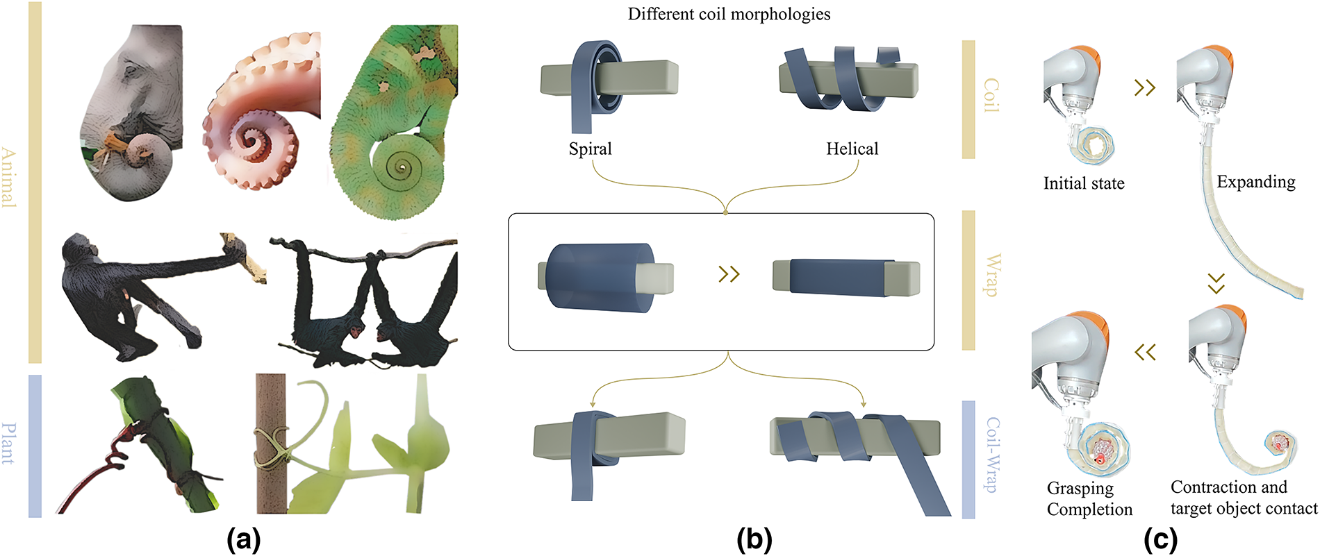
Biomimetic principle analysis.
active deformation to coil around the target object.
deformation of the flexible structure to conform to the object’s surface.
enhancing friction to increase stability.
To better understand and apply these biological phenomena, we define the coiling behavior (coil-wrap mechanism) as a biomechanical mechanism that achieves secure attachment and control of movement of a target object through the coupling of a helical configuration and sustained contact force. The structure is typically helical, capable of wrapping around, and conforming to the target’s surface via flexible or compliant structures, thereby applying continuous contact force to adapt to the shape, apply loads, or enhance friction to secure the object’s position.
Based on the aforementioned biomechanical principles, this study applies the bionic coiling principle to the design of a soft gripper (Fig. 1(c)), enabling various functions. For instance, whether it is plant tendrils conforming to supports or animal tentacles grasping prey, their compliant structures can adapt to the target’s shape, ensuring stable attachment. Additionally, snakes apply compressive force by gradually tightening their coils to control prey, while plants use tendril coiling to apply loads and secure their position on supports. Furthermore, while maintaining flexible contact, multiple coils can increase the friction between the soft gripper and the target object, improving gripping performance.
Drawing inspiration from the bionic coiling principle, this study designs a highly flexible, adaptable, and load-bearing bionic coiling soft gripper (CWG), offering a novel solution for efficient gripping in complex environments.
Structure and features
The structure of the soft coiling gripper proposed in this article is illustrated in Figure 2(a) and consists of four main components. The first component is a long air bladder that serves as the primary drive unit (Fig. 2(b)). It is formed by heat pressing nylon cloth and provides the necessary force for deployment by increasing the internal pressure. The second component is an elastic layer made from cut silicone rubber sheets, which are stretched before being fixed to provide contractile force. When combined with the main drive unit, this layer enables the gripper to change its shape. The third component is a short air bladder that acts as an auxiliary drive unit. Similar to the main drive unit but differing in size and function, it applies additional pressure to the target object by increasing its internal air pressure, ensuring conformity with the target. The fourth component is the outermost contact layer, which interacts with the target object or itself. This layer protects the internal structure and allows for the adjustment of friction during contact by selecting different materials. Subsequent sections will analyze the impact of various materials on gripping performance and discuss how to choose the appropriate material for the contact layer to ensure stable gripping.
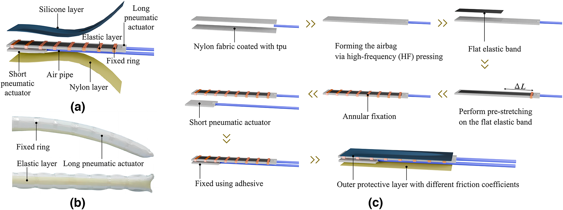
The structure and manufacturing process of CWG.
The fabrication process of the CWG involves the following steps. First, a high-frequency machine is used to heat press nylon cloth with a TPU (Thermoplastic Polyurethane) coating into a long strip-shaped air bladder, and an air tube is installed at one end for inflation. Second, the stretched elastic rubber is secured to one side of the air bladder using annular rings and glue. Then, the small air bladder is attached to one end of the large air bladder. Finally, silicone and nylon cloth are affixed to both sides as the contact layer to protect the internal structure and adjust the contact friction coefficient. A schematic diagram of the fabrication process is provided in Figure 2(c).
Motion principle
The CWG initially assumes a shape similar to an Archimedean spiral, which helps maintain stability during deployment and contraction. When the long air bladder is inflated, it straightens and exhibits sufficient stiffness to overcome the contractile force of the elastic layer, thereby deploying the CWG. Conversely, when the long air bladder is deflated, the elastic layer causes the CWG to return to its coiled state. Thus, by inflating and deflating the long air bladder, the CWG can switch between its deployed and coiled states to grasp target objects.
For lightweight objects, the contractile force of the elastic layer is sufficient to achieve gripping. However, for irregularly shaped objects, passive coiling alone may not allow the CWG to fully conform to the object’s surface due to its complex shape. In such cases, pressurizing the short air bladder provides additional normal pressure, enhancing contact between the CWG and the object’s surface, thereby increasing friction and preventing the object from slipping. During the release phase, the pressure in the short air bladder is reduced, while the pressure in the long air bladder is increased.
The outermost silicone layer serves to cover the internal air bladders and enhance the friction coefficient with the target object, enabling friction self-locking even with fewer coils. When the CWG is wrapped around an object and the object is pulled, the CWG remains coiled around the object’s surface due to friction. The parameters influencing the friction force during coiling include the friction coefficient between the object and the inner silicone layer of the CWG and the coiling angle. The relationship between these parameters will be discussed in detail in subsequent sections.
When a single CWG is used to grasp heavier objects, it may disengage due to the rotation of the target object. To mitigate this, a collaborative strategy is proposed, utilizing two CWGs as a pair. This configuration allows the two CWGs to constrain the target object from opposite directions, counteracting any rotational tendencies. Through this collaborative approach, the CWG can more effectively grasp heavy objects, enhancing both stability and reliability. In this scenario, the ability to retain the object depends on the friction between the CWG and the object. If the coiling angle meets the friction self-locking condition (to be analyzed in the next section), the CWG can maintain its grip regardless of the load, provided that its structure and materials remain intact.
Theoretical analyses
Two distinct wrapping configurations
By adjusting the spatial arrangement of elastic layers, CWG can generate two different motion modes, as shown in Figure 3. When the elastic layer forms a specific inclined angle with the pneumatic chamber, CWG exhibits Type A motion mode illustrated in Figure 3(a). Conversely, when arranged parallel and bilaterally symmetric, it demonstrates Type B motion mode shown in Figure 3(b).
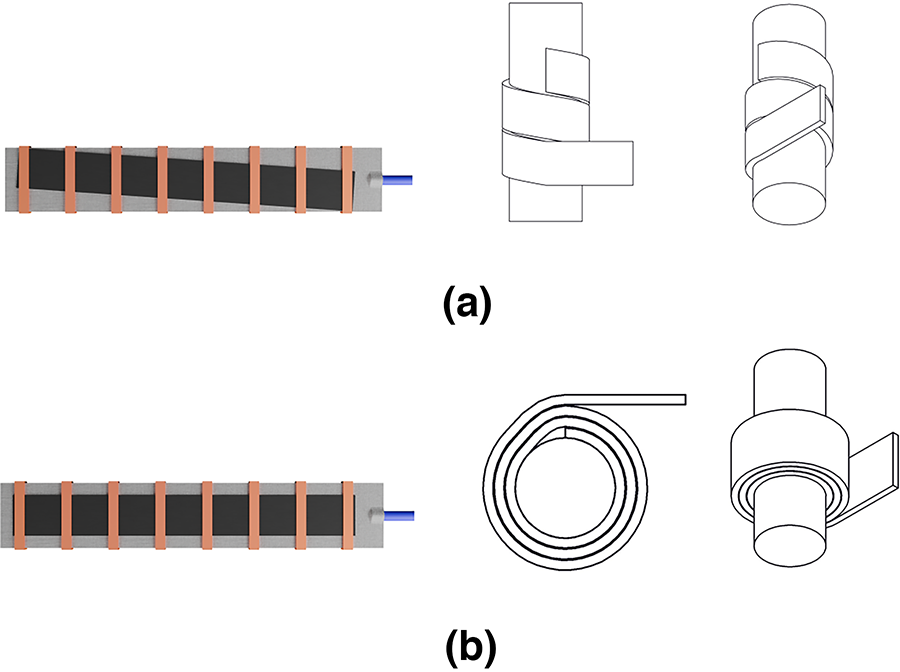
Different coiling configurations.
The contact mechanics model of Type A only involves interaction between the CWG’s inner surface and target objects. This configuration offers advantages in reducing manufacturing complexity and simplifying theoretical modeling due to its straightforward contact mechanism. However, since this configuration requires continuous multiloop wrapping around object surfaces, practical applications demand objects with sufficient axial length for complete wrapping. Due to this limitation, CWG struggles to complete full wrapping motions when handling objects with smaller dimensions.
Unlike Type A, Type B features a distinctive dual-contact mechanism: simultaneous external contact with target objects and internal self-contact between layers. This configuration requires comprehensive consideration of friction coefficient differences between inner/outer layer materials during structural design and mechanical analysis, necessitating a dual contact mechanics model for effective wrapping implementation. The advantage lies in its reduced axial length requirement and better adaptability to object dimensions. Additionally, the terminal section benefits from friction generated by outer layer compression, eliminating the need for additional structures to provide initial tension.
Considering Type B’s superior adaptability to various object dimensions and lesser constraints from manufacturing processes and theoretical modeling, this article will focus on analyzing Type B configuration and conducting prototype verification.
Contact friction force model
Before establishing the theoretical model, the following assumptions are made: The total length of the CWG is unstretchable, and the angular error caused by the CWG thickness not contacting the target object is negligible.
When the number of coiling turns exceeds one full circle, the additional angle beyond the complete coiling is defined as the overwinding angle θ1. Based on contact mechanics characteristics, the system is divided into three sections: section 1 (dual contact interface, angular range θ1) → section 2 (single object contact, angular range θ2) → section 3 (single self-contact, angular range θ3). The externally applied axial tension is denoted as F1. As shown in Figure 4(a).
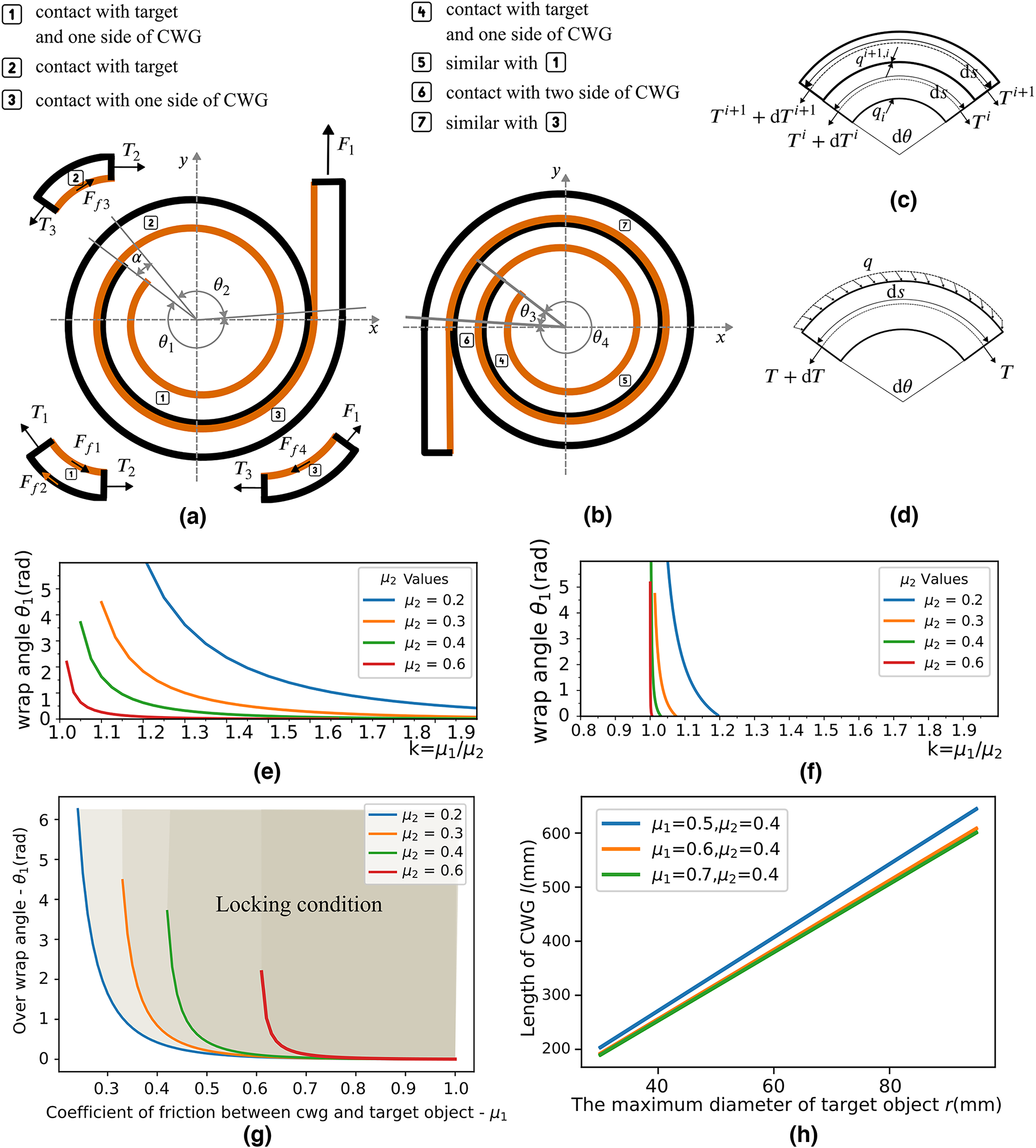
Analysis of the relationship between CWG wrap angle and friction force.
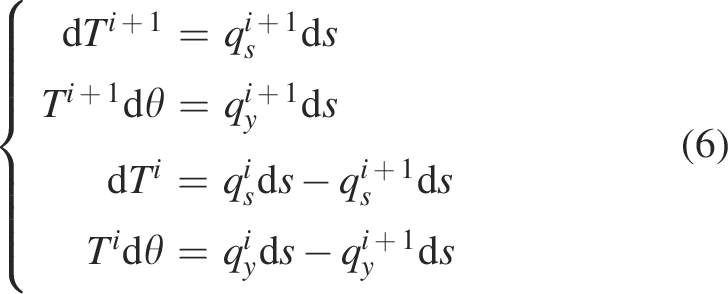
A mechanical equilibrium model is developed using the infinitesimal element method (Fig. 4(d)). For sections 2 (single object contact) and 3 (single self-contact), the normal constraint force distributions share similar characteristics and can be uniformly described by the following differential equations:
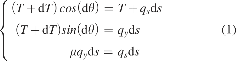
Given cos(dθ) ≈ 1 and sin(dθ) ≈ dθ, (1) is simplified to:
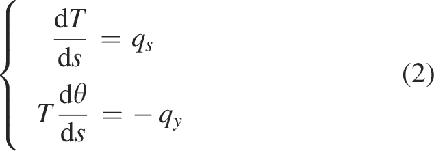
Solving (2) yields:

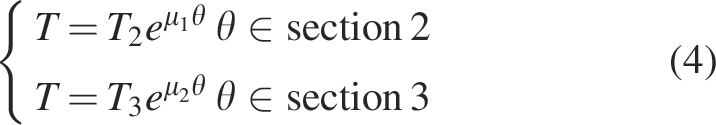
For sections 2 and 3, substituting initial conditions: for section 2, T = T2 when θ = 0; for section 3, T = T3 when θ = 0, we obtain:
Section 1 simultaneously contacts both the target object and the inner self-contact surface, experiencing friction forces from both sides (Fig. 4(c)). The force balance equations for section 2 are:
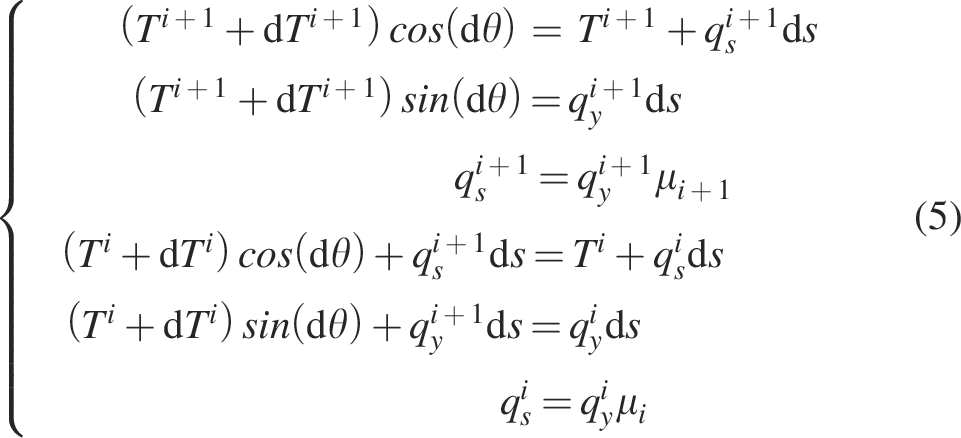
Using cos(dθ) ≈ 1 and sin(dθ) ≈ dθ, the equations simplify to:
Simplifying Equation (6) yields:
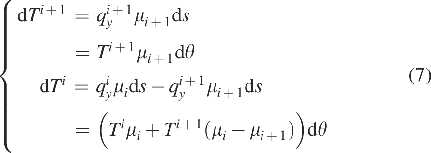
Integrating Equation (7) gives:
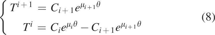
Given initial values
The friction coefficient between the CWG and the object is denoted by μ1, whereas the friction coefficient corresponding to the CWG’s external material is denoted by μ2. From Equation (9), the force distribution in section 1 is:

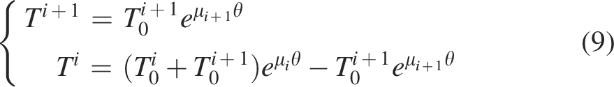
Since one end of section 1 is free (T1 = 0), substituting into Equation (10) gives:

Given the overwinding angle θ1, Equation (11) implies:

From Equations (4) and (12), the maximum friction force generated by the CWG under external force F1 is:
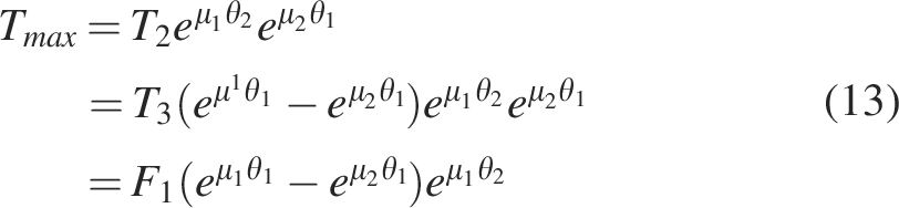
Let Tmax = λF1. When λ ≥ 1, the friction force exceeds the external force, leading to self-locking. The λ value is:

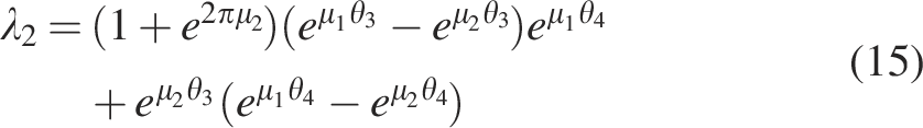
For multiturn winding (exceeding two full circle, As shown in Fig. 4(b)), the coefficient λ2 is derived as:
Critical conditions are analyzed as follows. The boundary condition for self-locking occurs when λ = 1. Key conclusions include:
Friction coefficient coupling
(1) When μ2 ≥ μ1, self-locking cannot be achieved through overwinding (Fig. 4(e)). (2) Defining the friction coefficient ratio
Overwinding angle optimization
For a given μ2, increasing μ1 reduces the required θ1. Therefore, high-friction inner-layer materials improve gripping performance (Fig. 4(g)).
Mechanism parameter correlation
The coupling between friction coefficients and the overwinding angle
The analysis demonstrates that differentiated friction design (high μ inner layer, low μ outer layer) effectively optimizes self-locking performance and engineering applicability. These findings provide critical guidance for flexible gripper design.
Experiment and Results
Contact layer friction coefficients
Based on the theoretical analysis, it is concluded that stable frictional self-locking in the CWG can be achieved only when the friction coefficient of the inner layer material is greater than that of the outer layer material, under certain winding angle conditions. This indicates that the frictional performance difference between the inner and outer layer materials directly affects the gripping effectiveness of the CWG. Therefore, it is essential to select appropriate materials for both the inner and outer layers of the CWG.
Silicone rubber, commonly used in soft grippers, is a flexible and elastic material with a relatively high friction coefficient and low hardness. It generates an adsorption effect when in contact with the target object and can deform to conform to its surface. This excellent surface adaptability not only enhances the frictional force between the gripper and the object but also helps prevent mechanical damage to the surface of the held object. Based on these considerations, this study selects silicone rubber as the material for the inner layer of the CWG to maximize the gripper’s flexibility and safety.
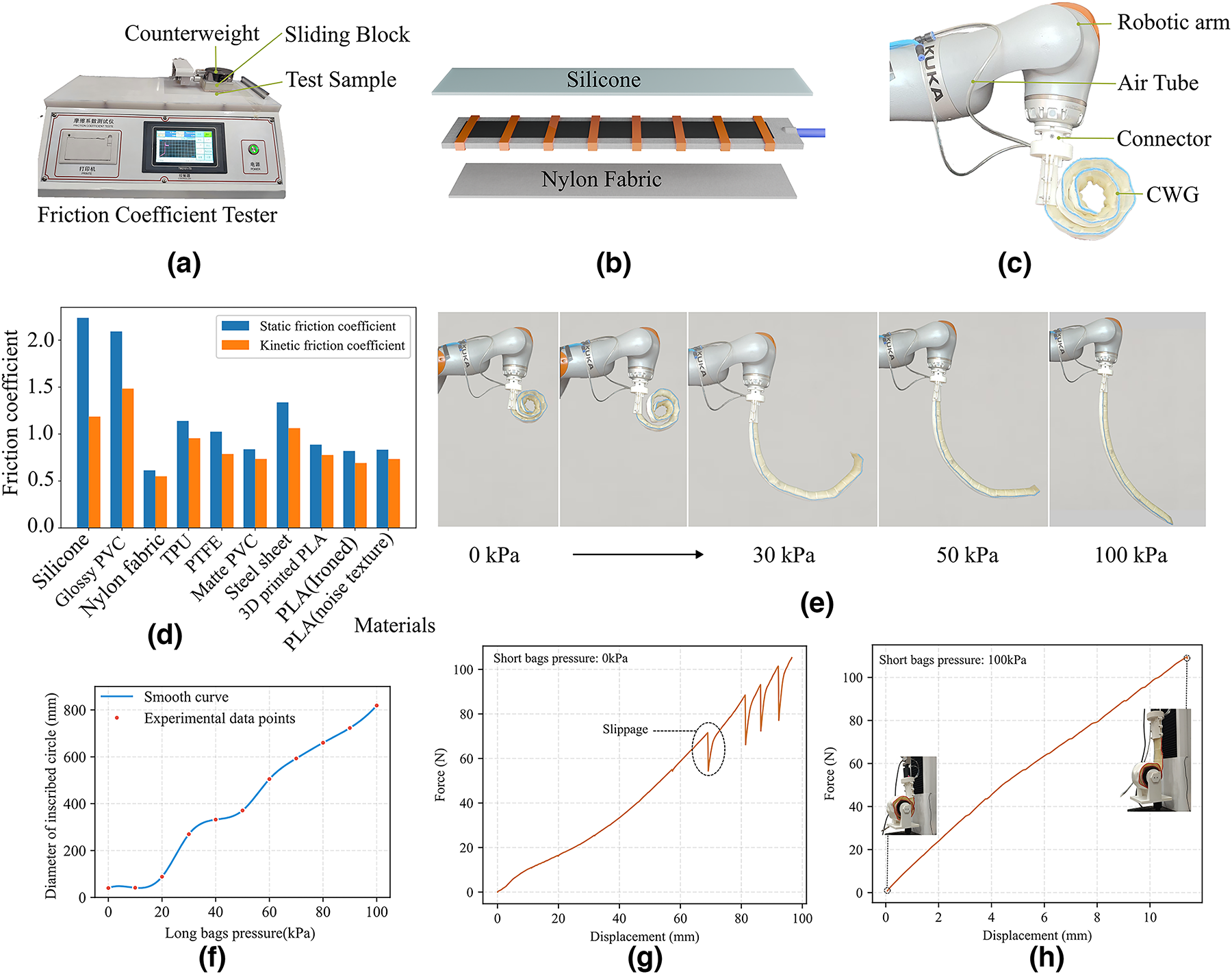
Once the inner layer material is selected, it is crucial to choose an outer layer material with a relatively low friction coefficient. In this study, several common materials, including silicone rubber, PVC (Polyvinyl Chloride), and nylon fabric, were selected, and the friction coefficients of their surfaces were measured using a friction coefficient tester (model: TM2101-T5). In the specific testing process, a 1.5 mm thick silicone rubber sheet was fixed at the bottom of the slider, and a sample of the material to be tested was secured to the test platform. A weight (712 g in total) was added to the slider (Fig. 5(a)). The sliding speed was set to 20 mm/min, and the friction coefficients of 10 materials were measured, with each test repeated three times to ensure data reliability and consistency.
Determining the materials for the inner and outer layers of the CWG and the prototype.
The experimental results (Fig. 5(d)) reveal significant differences in the static friction coefficients between silicone rubber and various materials, primarily due to the adsorption effect and deformation characteristics of the silicone rubber surface. Specifically, when silicone rubber contacts smooth, textureless materials, the strong adsorption effect between the material interfaces results in a higher static friction coefficient. In contrast, when silicone rubber contacts materials with a pronounced texture, the adsorption effect between the interfaces weakens, leading to a relatively lower static friction coefficient. Comparison of the experimental data show that the lowest static friction coefficient occurs between silicone rubber and nylon fabric. Therefore, nylon fabric was ultimately selected as the outer layer material for the CWG to maximize its frictional self-locking performance, ensuring that the gripper can function stably and reliably (Fig. 5(b)).
Morphology under different pressures
The motion of the CWG is achieved through the synergistic action of a long airbag and an elastic layer. A pneumatic control system enables active structural shape control by adjusting the internal pressure of the long airbag. Specifically, when the internal pressure increases, the long airbag undergoes radial expansion. During this process, the expansion force generated by the airbag and the contraction force of the elastic layer oppose each other, causing the structure to gradually unfold and reach the predetermined shape. Conversely, when the internal pressure decreases, the contraction force of the elastic layer takes over, driving the structure to transition toward a coiled state, thereby enabling gripping or releasing motions.
To test the CWG’s range of motion, a converter was used to mount the CWG at the end of a Kuka iiwa robotic arm (Fig. 5(c)). Two electronic proportional valves from SMC Corporation were employed in the pneumatic control unit to independently regulate the internal pressures of both the long airbag and the short airbag. At the start of the experiment, both air channels were set to 0 kPa. Subsequently, during testing, the pressure inside the long airbag was gradually increased, beginning from 0 kPa and rising in 10 kPa increments. The resulting morphological changes in the CWG are shown in Figure 5(e). The motion state of the CWG is represented by its inscribed circle diameter, and the relationship between the long airbag pressure and the inscribed circle diameter is shown in Figure 5(f).
Experimental findings indicate that the CWG can unfold and coil within a two-dimensional plane. During the unfolding phase, once the airbag inflates, the CWG can maintain its shape with a certain level of stiffness. This characteristic makes it convenient for a robotic arm or other carrier platform to move the CWG near the target object. When the pressure reaches 100 kPa, the CWG’s unfolding extent reaches its maximum. Continuing to increase the pressure beyond this point yields negligible additional structural changes, suggesting that regulating the pressure to a suitable level effectively controls the CWG’s morphological adjustments for different gripping requirements.
In the experiment, the internal cavity of the CWG had an initial diameter of 50 mm. For target objects smaller than this size, it is necessary to increase the pressure in the auxiliary airbag to provide additional stabilization. In addition, the auxiliary airbag can enhance the contact effect between the CWG and the target object. As shown in Figure 5(g) and (h), when the auxiliary airbag pressure is 0 kPa, multiple slips occur during the load increase process (indicating unstable contact); whereas at 100 kPa, no slips occur as the load increases, demonstrating better adaptability and friction self-locking.
Grasping lightweight objects
The function of CWG is similar to that of a spider monkey’s tail. It not only can wrap around fixed objects, but also can grasp lightweight objects through a contraction process after fully unfolding. In nature, a spider monkey’s tail acts as a “fifth limb,” capable of flexibly grabbing and wrapping around branches. This ingenious biomimetic inspiration endows CWG with high flexibility and adaptability when grasping objects. The primary aim of this experiment is to validate CWG’s performance in grasping lightweight small objects, particularly its ability to handle target objects of various shapes and sizes.
The experimental system consists of the CWG, a KUKA iiwa robotic arm, a pneumatic control system, and other components, with the CWG fixed at the end of the robotic arm via a conversion module. The pneumatic control system provides an adjustable air pressure source for the long and short air bladders of the CWG.
To thoroughly evaluate the adaptability of the CWG, a diverse set of test samples was selected. These samples included common items for daily use (e.g., water bottles, tennis balls, tissue boxes, and tool boxes), each differing in shape, material, and surface friction characteristics, as well as regular geometric objects (e.g., hexagonal prisms, polyhedra, rectangular prisms, and spheres) to assess the CWG’s grasping performance on standardized target shapes. The mass of these test samples ranged from 20 to 300 g, with characteristic dimensions from 25 to 120 mm. Such diversity in test samples enables a more comprehensive evaluation of the CWG’s overall grasping capability.
The entire grasping process consists of four main stages:
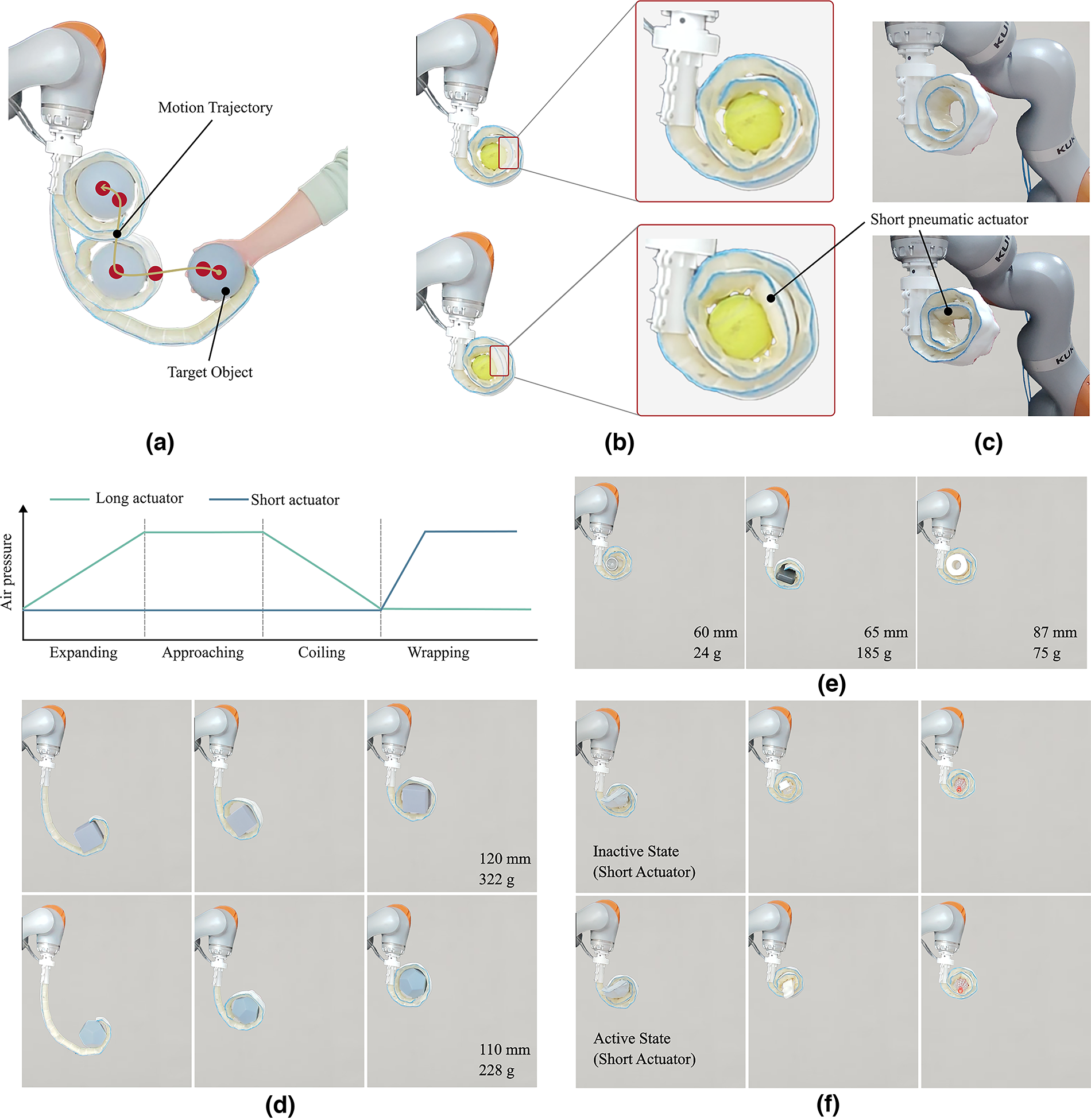
First, the air pressure in the long air sac is increased to 100 kPa, causing the CWG to fully unfold. At this stage, the CWG resembles an extended “biomimetic tail,” ensuring a broad area of contact or wrapping with the target object. The robotic arm is then moved, guiding the CWG into alignment with the motion path of the target object, ensuring precise contact in the subsequent phase. Depending on the target object, the robotic arm requires different motion trajectories. When the target object can move, the robotic arm only needs to ensure that the end of the CWG contacts the target object after deployment; subsequently, the arm can remain stationary, and the target object will be pulled toward the arm as the CWG contracts, with the object’s movement trajectory shown in Figure 6(a). When the target object’s position cannot be moved freely, the robotic arm needs to move along the trajectory shown in Figure 6(a). By reducing the air pressure in the long air sac, the CWG undergoes a gradual contraction. During the contraction process, the CWG wraps around the target object, covering its surface and grasping it. Finally, air pressure is applied to the short air sac to secure the target object. The short air sac, located at the end of the CWG, provides additional gripping force and stability, further improving the stability of the grasp.
The grasping test results of the CWG.
The process by which the CWG grasps standard geometric objects is illustrated in Figure 6(d), whereas its performance in grasping daily objects is demonstrated in Figure 6(e). In the experiments, grasping is defined as follows: After the CWG is fully deployed (long airbag pressure ≥ 100 kPa), the structure contracts by gradually reducing the long airbag pressure, achieving stable contact between its surface and the target object. With the assistance of the short airbag pressurization, the target object remains stationary for at least 10 s without external support, and no relative slippage or detachment occurs.
The short air sac of the CWG is crucial in ensuring the quality of the grasp. After the object is grasped, it maintains good contact with the surface of the target object, as shown in Figure 6(c). The overall movement trajectory of the grasped object is depicted in Figure 6(a), where the CWG initially contacts and begins to wrap around the object during stage three, eventually completing the wrapping and grasping process. At this point, applying pressure to the short air sac increases the contact area, thereby keeping the target object in a more stable grasped state (Fig. 6(b)). In regular operations, if the object to be grasped is small or has an irregular shape, the short air sac assistance (Fig. 6(f)) is especially necessary to enhance the reliability of the grasp.
From the experimental results, it is evident that within the test range of target objects with a mass less than 300 g and a maximum inscribed sphere diameter between 25 and 120 mm, the CWG is able to complete the grasping task and demonstrates good morphological adaptability. For noncylindrical objects, after the initial grasp, continuous application of air pressure to the short air sac can enhance the contact between the CWG’s end and the target object, resulting in better grip stability. Even under certain external force interference, it is difficult for the target object to escape from the CWG’s grasp. Therefore, CWG proves to be highly feasible and adaptable in scenarios involving small, lightweight, and geometrically diverse objects.
Friction-based self-locking
The main innovation of this study lies in using the frictional self-locking phenomenon to enhance the load-bearing capacity of soft grippers, thereby addressing the issue of insufficient grasping force. The unique structural characteristics of soft grippers dictate that they are superior in tensile strength compared with compressive strength. Therefore, by wrapping around an object and utilizing the principle of frictional self-locking, the load-bearing capacity is converted from the compression dimension to the stretching dimension of the robot, thus improving its load-bearing capability. This innovation provides an important breakthrough in the grasping ability of soft grippers in practical applications, especially under high load conditions, where it enhances stability and reliability.
In the theoretical model presented in this article, we demonstrate that as long as the wrapping angle meets specific conditions, the frictional self-locking state of the soft gripper can be achieved, effectively enhancing its load-bearing capacity. To verify the correctness of this theoretical model and analyze potential issues that may arise during actual grasping, this study designed related experiments. The core aim of the experiment is to verify whether frictional self-locking can be realized during the actual grasping process, and to further explore the stability and load limits of the wrapping structure.
In the heavy object grasping test using a single CWG, rotational torque may be generated by the object, which can affect the experimental results. Therefore, when testing the frictional self-locking effect, we adopted a method similar to how plant tendrils attach to supports, fixing the CWG on a bracket to reduce the interference of rotational torque on the results.
In the specific implementation process, the CWG was first wrapped around a fixed crossbeam, and the number of hanging weights below was gradually increased (as shown in Fig. 7(a)). Next, we replaced the CWG’s conversion joint to make it easier for handheld operation (Fig. 7(b)), and conducted another round of tests.
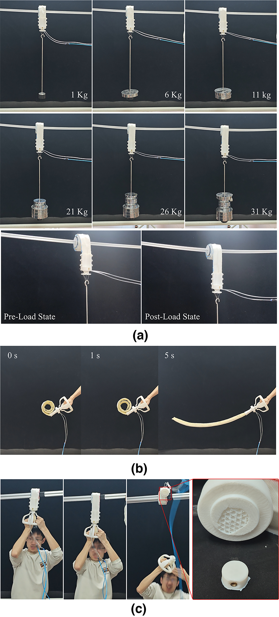
Friction self-lock verification and load testing.
The experimental results showed that when the load increased from 1 to 31 kg, the hanging point moved downward. However, from the side view, the wrapped part of the CWG did not slide, indicating that the frictional self-locking phenomenon remained effective. In the handheld experiment, when the load reached 60 kg, although the conversion joint broke, the fixed part of the CWG remained stable, without any sliding (as shown in Fig. 7(c)). This phenomenon suggests that frictional self-locking can not only effectively increase load-bearing capacity but also allow the soft gripper to maintain strong grasping stability under higher loads.
To further verify the influence of material friction coefficients on winding self-locking, we selected PLA (Polylactic Acid) as the target object (printed into a 60 mm diameter cylinder) and used nylon woven fabric, TPU, and silicone film as inner and outer layer materials for combination tests. First, the friction coefficients of the selected materials were measured using a friction coefficient tester (model: TM2101-T5), with results shown in Figure 8(a).
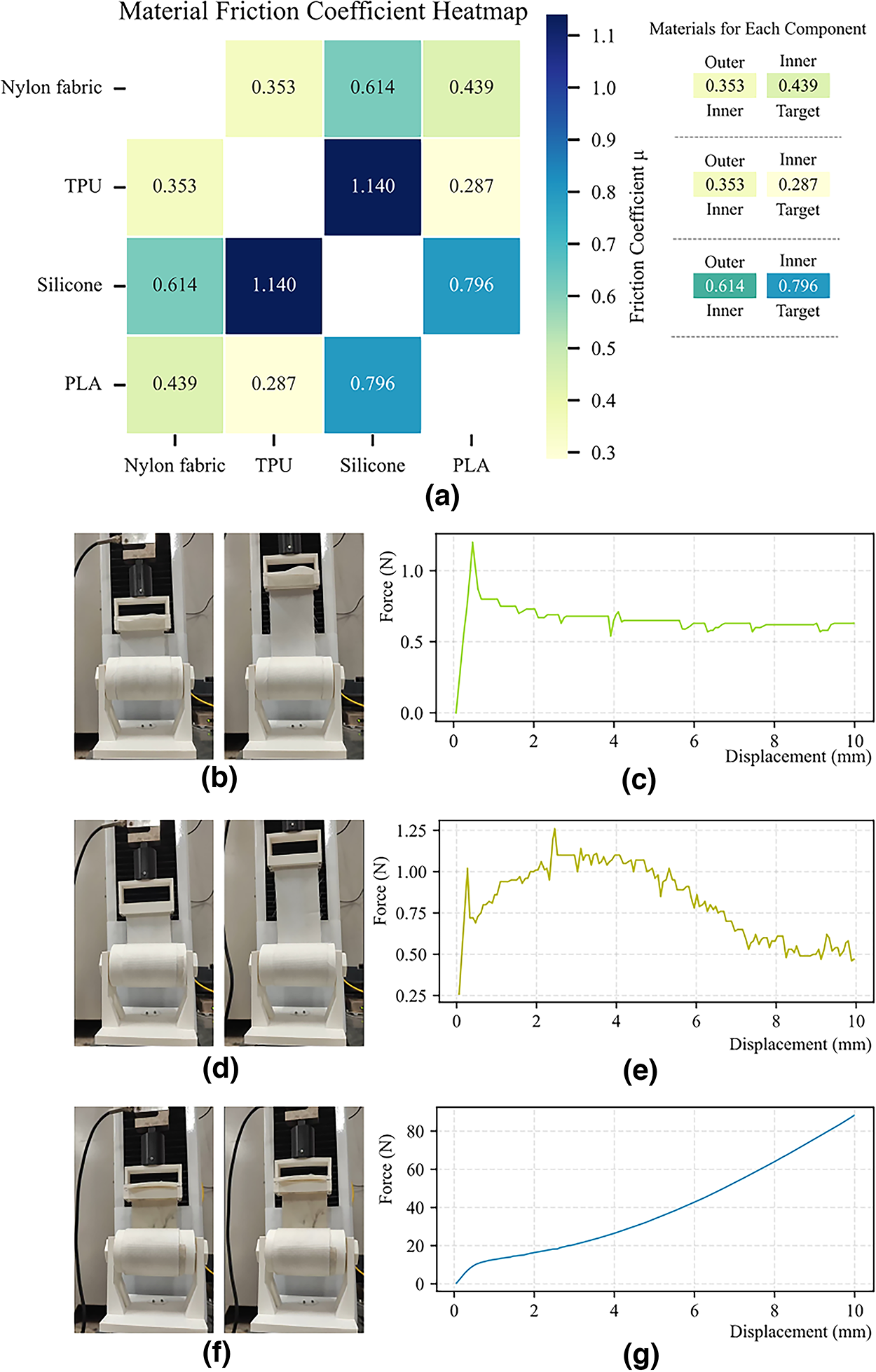
Effect of materials with different friction coefficients on friction self-locking in the winding state.
Then, an FBS100NS tensile-compression machine was used to stretch the materials wrapped around the cylinder, measuring the force–displacement relationship curves. The inner and outer layers were switched for three experiments, respectively. The first experiment used nylon woven fabric as the inner layer and TPU as the outer layer (Fig. 8(b)); the second used TPU as the inner layer and nylon woven fabric as the outer layer (Fig. 8(d)); the third used nylon woven fabric as the outer layer and silicone as the inner layer (Fig. 8(f)). The experimental results indicate that when the friction coefficients between the inner/outer layers and the target object material are similar, friction self-locking cannot be achieved (Fig. 8(c) and Figure 8(e)). However, differences in friction coefficients significantly affect the force value at which sliding occurs. When the friction coefficient between the inner layer material and the target object is larger (and greater than that between the inner and outer layers), friction self-locking can be realized: as shown in Figure 8(g), the tensile force continues to increase with displacement, without fluctuations or stabilization at a specific value. This displacement variation mainly arises from the elastic deformation of the materials and the tightness of components.
Through this experiment, we further confirmed that the downward movement of the hanging point was caused by the thickness of the CWG and its soft material properties, which led to certain compression deformation under load. Future research can improve the connection structure to enhance the overall stability of the CWG, thereby improving its performance under higher loads. However, despite the compression deformation issue, this experiment successfully verified the potential application of frictional self-locking in enhancing the load-bearing capacity of soft grippers.
Collaborative usage
When a single CWG is used to grasp heavier objects, the gripper’s effectiveness may be compromised due to the potential for the object to spin. This occurs because, when the object is heavy or the grasping force is insufficient, a single CWG may struggle to provide enough antirotational torque, resulting in the object spinning and thereby impacting the stability and safety of the grasp. To address this issue, a configuration using two CWGs symmetrically arranged and working in tandem can be employed. The cooperative action of the two CWGs effectively suppresses the tendency of the object to spin, providing a more balanced grasping force and ensuring stability and reliability during the grasping process.
To validate the effectiveness of the dual-CWG collaboration and perform load testing, a dumbbell was chosen as the experimental object. First, a single CWG was tested. As shown in Figure 9(a), during the grasping of the dumbbell, the object rotates due to its mass and shape characteristics, preventing successful lifting. This phenomenon indicates that a single CWG cannot effectively handle the object’s rotation, limiting its application in certain scenarios. Next, two CWGs were symmetrically arranged and fixed to the end of the robotic arm, and the dumbbell grasping experiment was conducted again. The results, shown in Figure 9(b), reveal that the cooperative action of the dual CWGs significantly enhanced the grasping stability, preventing the rotation of the dumbbell and successfully completing the task of grasping and lifting. This demonstrates that the symmetric arrangement of two CWGs can effectively suppress the object’s rotation, making the grasping process more stable and reliable.
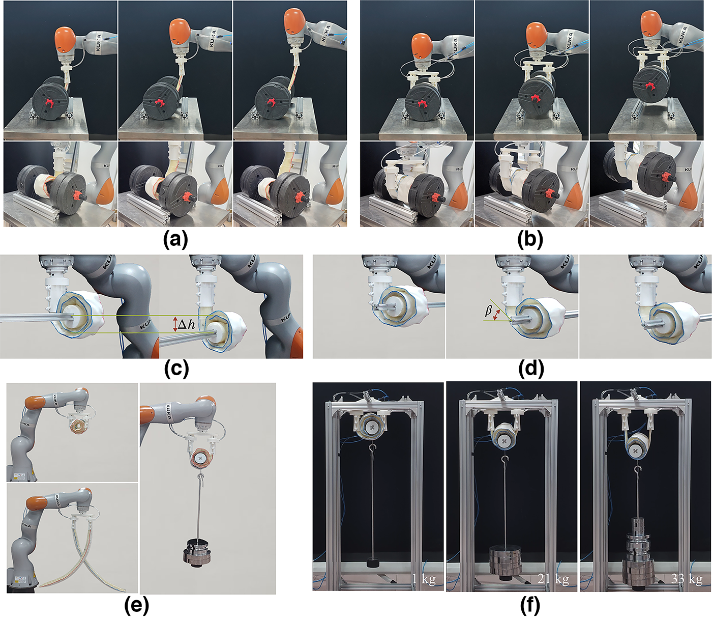
Dual CWG cooperative usage and load testing.
To further test the performance of the dual-CWG collaboration, load tests were also conducted using both a robotic arm and a fixed stand. The test results are shown in Figure 9(e) and Figure 9(f). According to the experimental data, the dual-CWG collaboration not only prevents the rotation of the target object but also achieves more stable grasping under varying load conditions, with higher grasping stability and load-bearing capacity compared with the use of a single CWG.
Additional performance metrics: Fatigue, energy, and adaptability
To further verify the CWG’s mechanical durability, dynamic response, energy efficiency, and grasping applicability at tilted angles, targeted supplementary experiments were conducted. These tests evaluate long-term stability under cyclic loading, real-time response, energy utilization, and robustness in nonideal environments. Results are shown in Figure 10. The durability test examines performance degradation under repeated mechanical stress using a dedicated test rig on an Instron 5567 tensile machine, with one end fixed and the other subjected to cyclic external load (60 mm end displacement, peak 44 N, over 300 cycles, total ∼5 h). Results indicate force consistency of 0.78% and energy consistency of 0.68% after 300 cycles, with no obvious degradation. In future applications, more durable materials can be replaced based on conditions to enhance durability.
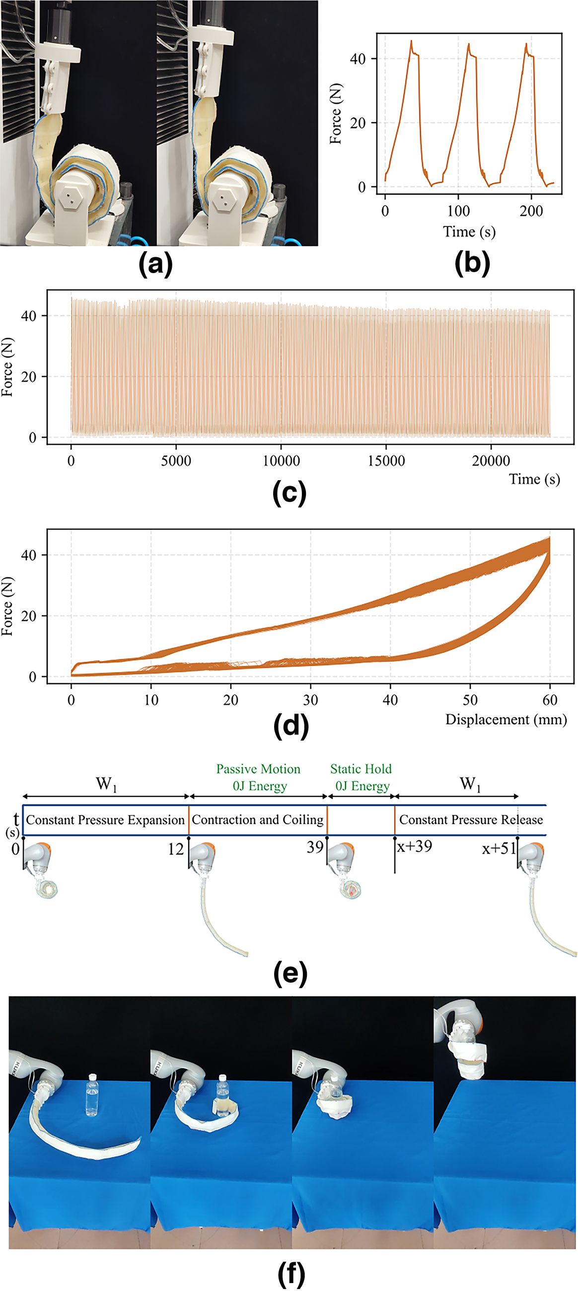
Performance metric tests of the CWG.
The dynamic performance and energy efficiency tests focus on the CWG’s response time and energy consumption. The deployment stage (constant pressure inflation at 100 kPa) takes 12 s, the passive winding stage (natural curling) takes 27 s, and the release stage is identical to deployment (Fig. 10(e)). In the full grasping cycle, only the deployment and release stages require external energy input, calculated as approximately 0.3 kJ based on pressure and airbag volume. The CWG’s dynamic response is relatively slow, making it suitable for low frequency operations currently. In future work, we aim to improve its dynamic performance (e.g., via optimized materials or control algorithms) to cover more application scenarios.
The tilt angle grasping test evaluates CWG’s performance in nonhorizontal environments, as shown in Figure 10(f). Results indicate that CWG can grasp lightweight objects from multiple angles. However, at large tilt angles (e.g., >60°), morphological deformation occurs, preventing friction self-locking for heavy loads. In future work, we will increase stiffness to ensure effective grasping across various angles.
Capture failure analysis
In the aforementioned experiments, it has been verified that CWGs can effectively grasp lightweight small objects, and through the frictional self-locking mechanism, they can achieve stable grasping of larger loads. However, during actual testing, we found that when the target object’s surface is relatively smooth, the frictional force is insufficient to guarantee the CWG’s self-locking effect, leading to grasping failure. This situation typically occurs with objects made of smooth materials, such as metal or smooth plastic, whose low friction coefficient makes it difficult for the CWG to provide enough grasping force, resulting in slippage and detachment of the object (as shown in Fig. 9(c)).
Furthermore, in scenarios where a single CWG is used, if the target object has a tendency to rotate, the stability of the grasp will also be compromised. In such cases, the object may spin during the grasping process, preventing the CWG from maintaining an effective winding state, ultimately causing the grasp to fail (as shown in Fig. 9(d)). This phenomenon indicates that a single CWG’s grasping ability is limited when faced with object spin or smooth surfaces, particularly in tasks that involve handling large loads or require high grasping stability, where the CWG’s performance will significantly degrade.
Therefore, to address this issue, further improvements to the CWG design are necessary. For example, optimizing the texture of the CWG’s grasping surface or adding additional frictional materials can enhance its grasping ability on smooth surfaces. These improvements will help extend the CWG’s application range in complex and high-load environments, improving its adaptability and grasping effectiveness across various scenarios.
Conclusion
To address the limitations in load-bearing capacity of soft grippers, this study adopts a biomimetic approach, drawing inspiration from the coiling behaviors of plants and animals in nature. By analyzing their mechanical characteristics, these traits were translated into engineering design, ultimately resulting in the development of a biomimetic coiled soft gripper CWG.
The CWG utilizes a dual-layer pneumatic actuation system, where the primary air sac is responsible for shape switching, and the auxiliary air sac enhances the frictional contact with the object’s surface. Through the combination of helical coiling motion and flexible deformation characteristics, the CWG is capable of performing grasping actions in two phases: preexpansion and adaptive coiling. During this process, the soft gripper can actively conform to the surface of irregular objects, ensuring the stability and precision of the grasping process. In particular, the embedded auxiliary air sac provides stable pneumatic support, ensuring good contact with the target object, and by optimizing the coiling angle and friction coefficient of the contact layers, the contact surface’s friction is further enhanced, thus increasing the grasping force.
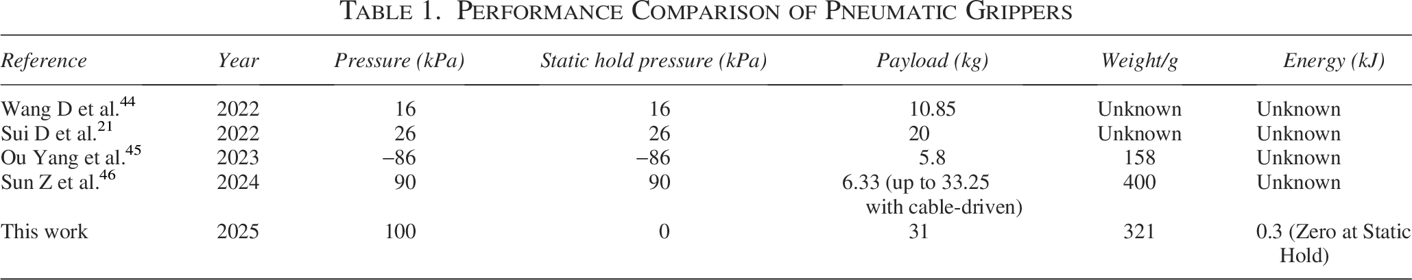
The continuous normal pressure generated by the helical structure triggers the static friction self-locking effect, enabling the gripper to surpass the load capacity limitations of traditional soft grippers at lower drive source strengths. This mechanism makes the load-bearing capacity of the CWG directly dependent on the strength of the materials used, rather than the output power of the drive source, which significantly improves the efficiency and application range of the gripper. Experimental results show that the CWG not only successfully grasps objects of various shapes and sizes but also significantly enhances its load-bearing capacity through the frictional self-locking mechanism, demonstrating considerable potential for practical applications. With similar studies, CWG leads in payload (31 kg at 100 kPa) and achieves zero energy consumption during static holding. Payload can be further enhanced by material changes. Dynamic performance is weaker, a key area for future improvements (The performance comparison of related studies is shown in Table 1).
Performance Comparison of Pneumatic Grippers
In summary, the CWG soft gripper presented in this article combines the flexible characteristics of soft grippers with the frictional self-locking theory, not only greatly improving the grasping load capacity but also eliminating the need for high-power drive sources, making the gripper operation more efficient and energy saving. Additionally, the fully flexible structure of the CWG enables it to adapt to target objects of varying sizes and shapes, ensuring good grasping adaptability. Furthermore, the analysis of frictional self-locking conditions provides a theoretical basis for further optimizing the design of soft grippers, particularly in terms of selecting appropriate structural designs and optimizing parameters.
However, the current prototype design still has certain shortcomings. First, the CWG may undergo deformation during nonvertical grasping, resulting in failure to grasp objects. To overcome this issue, future research will focus on improving the gripper’s rigidity to ensure stable operation in multiple directions. Second, the current operational mode of the CWG is relatively simple, lacking sufficient flexibility and controllability. To address this, future research will further enhance the controllability of the gripper’s morphology, with particular emphasis on the control of coiling motion and various coiling forms, aiming to achieve more precise and diverse grasping control to meet more complex application needs.
Authors’ Contributions
C.W. conceived and designed the project, and carried out the article writing and revisions. J.Y. supervised the research work and contributed to the article editing. X.Y. assisted with experimental execution and data organization. H.F. supported the fabrication of the prototype. S.Z. and W.Z. provided theoretical guidance throughout the research.
Footnotes
Acknowledgments
The authors thank Weihua Gao and Xinwei Yue for their help in the experiments.
Author Disclosure Statement
No competing financial interests exist.
Funding Information
This work was supported by the National Natural Science Foundation of China (Grant No. 52375030).
Supplemental Material
Supplemental Material
Supplemental Material
Supplemental Material
Supplemental Material
References
Supplementary Material
Please find the following supplemental material available below.
For Open Access articles published under a Creative Commons License, all supplemental material carries the same license as the article it is associated with.
For non-Open Access articles published, all supplemental material carries a non-exclusive license, and permission requests for re-use of supplemental material or any part of supplemental material shall be sent directly to the copyright owner as specified in the copyright notice associated with the article.