
Abstract
The need for freeform surfaces are widely recognized in the optical, aerospace, biomedical, and automotive industries. However, the fabrication of freeform surfaces is very difficult and expensive because of the involvement of advanced, multi-axis, dedicated machining processes. In many applications, the machining surface needs further polishing to reduce the surface roughness. The main aim of this work is to investigate the flexible pad polishing process for the finishing of the freeform surface. To achieve this, a flexible pad polishing setup is developed in two-axis configuration that can be integrated with a diamond turning machine or any other computer numerical control (CNC) machine and capable to polish the conventional rotationally symmetric surfaces as well as freeform surfaces. The polishing parameters for the developed polishing head are optimized for the nano-finishing of the freeform mold surface of Stavax ESR steel. The effectiveness of the current polishing setup is demonstrated by measuring the improvement in surface roughness height and profile. Test results reveal that the improvement on the freeform surface is significant, that is, surface roughness (Ra) reduces from 220 nm to 25 nm while keeping the profile within the desired tolerance.
Introduction
The surfaces which are not symmetric around any rotational axis are known as freeform surfaces. A typical freeform surface includes toroidal, bi-conic, and microlens arrays. The application of freeform surfaces is increasing rapidly in optical, automotive, aerospace, and biomedical industries.1, 2 Freeform surfaces are used in optical systems to improve the performance in terms of reduced optical aberrations and small system size. Few applications of freeform surface are in microscopy, telescopes, lithography system, satellite imaging system, prostheses, etc. 3 Due to complicated shapes and geometrical features, the manufacturing of freeform surfaces requires multi-axis computer numerical control (CNC) machines. Usually, three- to six-axis CNC machines are used to generate required profile accuracies. Various manufacturing methods such as grinding, diamond turning, 3D printing, and precision milling are utilized to fabricate the freeform surfaces.4, 5 These shape generation processes always leave some irregularities on the surface due to various process-related complexities.6, 7 The machining of freeform surface for optical applications is usually done in slow slide servo and fast tool servo configuration of ultra-precision diamond turning. Slow slide servo machining is mostly used for continuous type surface and is performed at very low spindle speed.8, 9 Large cycle time and poor surface finish are some of the main drawbacks of slow tool servo method and, therefore, a post polishing step is required which should not affect the already achieved profile. Freeform shape generation by multi-axis grinding machine followed by polishing on the multi-axis polishing machine is another important and mostly used process for fabrication of precision freeform surfaces. However, this process is relatively more expensive due to the involvement of a dedicated precision multi-axis polishing machine. Conventional CNC machines are also capable of generating freeform surfaces, but the achieved surface finish is not at the nanometer level and, therefore, post polishing is often required. Many polishing techniques such as chemical-mechanical polishing (CMP), polymer-based finishing, magnetic abrasive finishing (MAF), magnetorheological finishing (MRF), and bonnet polishing are explored by researchers to polish the freeform surfaces. 10 CMP is the oldest polishing process to perform the finishing of freeform surfaces. Initially, due to the absence of multi-axis platforms, this process is dependent on the expertise of the operator. 11 The advancements in the automation sector enable flexible tool path motions that enhance the performance of CMP. 12 Polymer-based polishing provides an elastic polymer medium for finishing. These elastic polymers are used in the wheel to polish the freeform surfaces. This process provides an improvement in the surface finish, but profile control is relatively difficult in this case. 13 In the MAF process, various parameters, that is, feed, the gap between polishing tool and workpiece, polishing tool rotational speed, etc., are studied to verify the effects of polishing for freeform surface.14, 15 Many MRF-based polishing setups are developed to polish the freeform surfaces. The process parameters of MRF such as current to change the magnetic field, tool rotation speed, and working gap are studied and optimized.16, 17 The MR fluid composition is studied to optimize it for nano-finishing operation.18, 19 Due to complex shape of freeform surface, the polishing forces are also difficult to control. To understand the variation of the polishing forces, various theoretical and experimental investigations are performed for polishing of freeform surfaces.20–22 Irrespective of the finishing capability of the MRF process, it is a relatively very slow process compared to conventional polishing and suitable only after achieving some level (~less than 100 nm) of surface finish on the targeted workpiece. Abrasive flow finishing techniques are also used to polish the freeform surfaces, but these techniques are mostly used for mechanical components, that is, knee joint, and not explored for optical applications.23, 24 Bonnet polishing or sub-aperture polishing technique is developed to polish the complicated freeform surfaces, where the pressure inside the bonnet is utilized to control the polishing forces. The process is capable to polish the selected area of the surface. The parameters affecting the performance of this process are also studied for the finishing of freeform surfaces.25, 26 Precise polishing tool path on surface plays a significant role in maintaining the required profile accuracies. Various approaches are reported in the literature for deterministic polishing and the generation of accurate tool path during machining and polishing.27, 28 All the above processes have their relative advantages and limitations. Moreover, most of these techniques are explored for mechanical components only. However, in case of freeform optical components, improving the surface finish up to nanometric level with sub-micrometer profile accuracies is still an active area of research.
In this article, a flexible pad polishing process is designed and developed which can easily be integrated on an existing shape generation platform. The improvement of the surface roughness of a freeform mold surface has been achieved by using the developed flexible pad polishing process. The developed flexible pad polishing setup is attached to a diamond turning machine to use the precise machine slides. The base freeform shape is fabricated on a multi-axis milling machine and polished by using the developed polishing setup. The influence of polishing parameters on surface quality is studied experimentally. Further, the optimization experiments are performed to achieve the minimum surface roughness. Additionally, the effect of post polishing on the surface profile is studied by measuring it before and after polishing. A detailed analysis of surface finish improvement is done by SEM and optical profilometer.
Development of flexible pad polishing setup
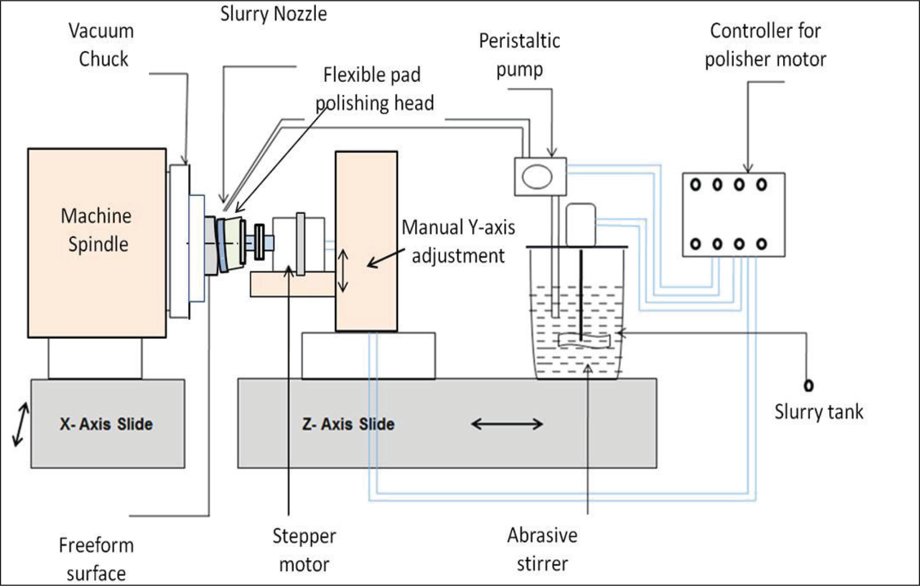
The nano-finishing of freeform surfaces without disturbing the surface shape is very challenging by conventional polishing methods. 29 All well-known and capable polishing techniques are very expensive and have their complexities as discussed in the previous section. Keeping in view, an effective and simple polishing technique, flexible pad polishing has been designed and developed. In the developed polishing setup, a two-axis diamond turning machine is utilized to mount the setup and to carry out the polishing operation. The use of the CNC lathe machine ensures the precise motion control required for the polishing setup. 30 Figure 1 shows the illustration of the flexible pad polishing setup.
A specially designed and fabricated tool post is used to mount the motor on the machine’s Z-axis. Compatibility with the diamond turning machine design and load constraints of slides and operations to be performed are considered for the design of the tool post. A stepper motor is mounted on the tool post with the help of a designed clamp. The different parts of the tool post and the motor clamp are designed to maintain the rigidity and to minimize the effects of motor vibrations. A flexible pad is developed to adapt the shape of the freeform surface at the polishing zone.
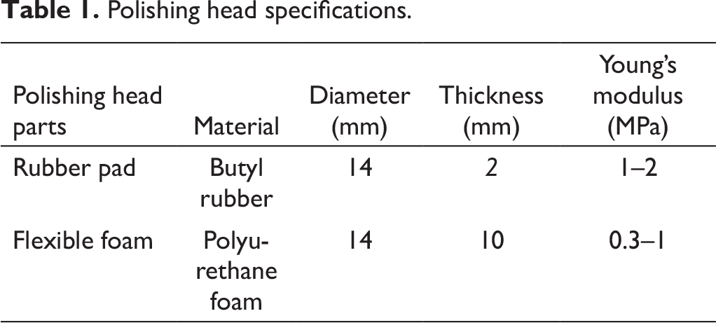
The schematic of the polishing head, including contact zone of the polishing head and freeform surface, and the actual view of the polishing head, is shown in Figures 2(a)–(c). The butyl rubber pad is attached with the flexible polyurethane foam by adhesive to provide it the required flexibility. The butyl rubber is selected as a pad material due to its good flex properties, good flexibility with a shore hardness of 30A–40A. As the polishing forces are dependent on the thickness of the selected foam, there is a trade-off between foam thickness and polishing forces. The foam thickness is selected based on initial experimental trials by checking the polishing effects at different foam dimensions. The properties and dimensions of the foam and rubber pad are given in Table 1 and Figure 2(e).
Schematic diagram of the designed flexible pad polishing setup.
Polishing head specifications.
The insulation tape is glued at one side of the rubber pad in such a way that it will envelope the flexible foam as shown in Figures 2(a) and (d). The foam is covered to protect it from slurry and to maintain its hardness/flexibility throughout the polishing process. The foam and flexible pad are attached to the aluminum holder with the adhesive, which is further attached to the motor shaft with the flange coupling. The detailed view of the flexible polishing head is shown in Figure 2(d). Figure 2(b) shows the relation between the flexible pad and the freeform surface during the polishing process. To achieve efficient polishing, without affecting the base profile, the polishing head axis vector i should be deflected by an angle θ with the surface normal vector j in opposite to the feed direction k. The tilt of the pad requires its adjustment with the freeform surface in contact, which is achieved due to the flexibility provided by the foam with a suitable compression factor. Hertzian contact model is considered to define the contact zone between the freeform surface and the polishing pad. The Hertzian model considers the contact zone as an elliptic shape and maximum polishing force at the center of the ellipses.
31
The contact area, force, and pressure distribution as per the Hertzian contact model are given in Equations (1)–(3).
32
As elastic rubber pad is of flat shape, it presses the freeform surface having the best fit sphere radius (R). The contact area between the pad and the surface ‘a’ can be written as

where d is the displacement toward the surface after touching the highest point of the freeform surface. The applied force (FN) depends on Poisson’s ratios and young’s modulus of the polishing pad and freeform surface. It can be given as
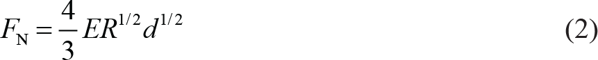
where E is derived from Poisson’s ratio and elastic modulus of the polishing pad and freeform surface. Once the force and area of the contact zone are known, the pressure at the contact zone can be calculated as
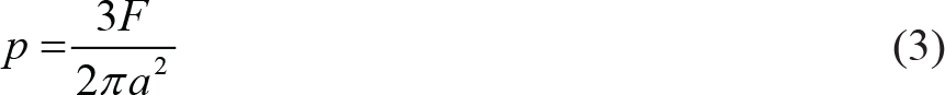
In the above equations, the contact area a and displacement d are related to the applied force and the pressure p.
Flexible pad polishing head: (a) schematic diagram of the flexible polishing pad, (b) schematic of the flexible pad and the freeform surface contact, (c) actual view of polishing pad and the surface, (d) detailed view of the polishing head, and (e) image of polishing pad surface with groove specifications.

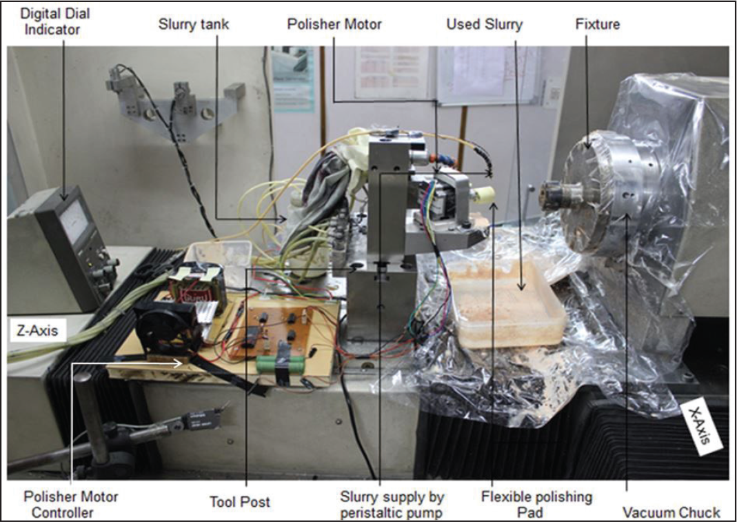
The flexible pad is attached to the motor shaft with the help of flange coupling. A motor is used to rotate the polishing pad against the workpiece in the opposite direction to the rotation of the workpiece under CNC control. A control circuit is designed and fabricated to control the stepper motor speed. The slurry tank is placed on the machine Z slide. Cerium oxide (CeO2) with an average grain size of 2 μm is mixed with water. The concentration of slurry is maintained as 5% of CeO2 abrasive particles mixed with deionized water. The slurry tank is provided with continuous steering arrangement to avoid the sedimentation of abrasives and to maintain the concentration of the slurry. A slurry tank provided with variable speed peristaltic pump is used to supply the slurry to the polishing zone. The polishing head speed is fixed at low speed and the slurry nozzle is aligned to drop the slurry on the pad surface or on the contact zone of the pad and surface to minimize the splashing. The face of the polishing rubber pad is provided with concentric circular grooves for effective slurry flow in the polishing pad and ensures its proper utilization. The image of the polishing pad surface with grooves is shown in Figure 2(e). Vacuum-based fixture is used to hold the freeform surface at X-axis. The fixture has collet-based clamping to hold the workpiece. A CNC program is written to provide the X- and Z-axis movement during the polishing of the freeform surface. Figure 3 shows the actual view of the polishing setup on the two-axis diamond turning machine.
Base freeform shape generation by milling
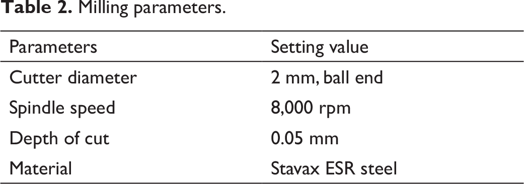
The experiments are performed to examine the effect of polishing parameters on the surface quality of freeform optics. For polishing experiments, samples with freeform shapes are generated by the multi-axis milling process. Stavax ESR steel, a premium grade stainless steel, is selected as a specimen. Due to high corrosion resistance, better polishability, high wear resistance, and good machinability, it is widely used in molding applications. The main ingredient of this material includes Cr—13.6%, Si—0.9%, Mn—0.5%, C—0.38%, V—0.3%. The hardness of this material is ranging from 45 HRC to 50 HRC. The targeted product from the current research is a mold for freeform optical components, which is one of the main reasons behind the selection of Stavax ESR steel. Freeform profile design for the current work is given in the form of seven-degree polynomial equation as follows:
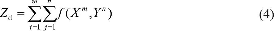
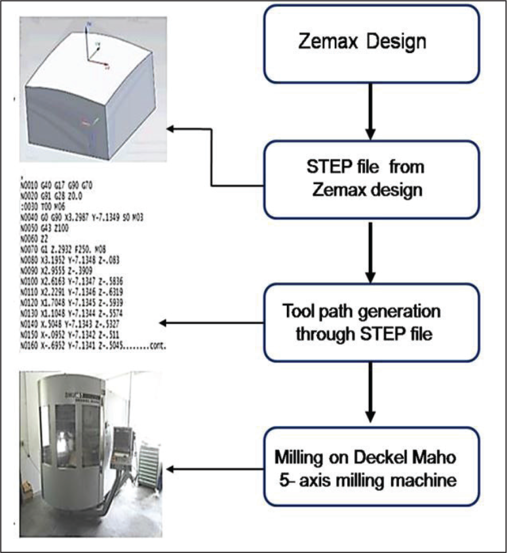
where Zd is the design sag of the surface. X and Y terms represent the coordinate values of X- and Y-axis, respectively, m and n are degree of the polynomial equation. The design file from Zemax (optical design software) is imported in the STP file format. This format is widely used to provide input for computer-aided manufacturing. The imported STP file is fed into the controller software of Deckel Maho (DMG) 5-Axis Machine. To generate the freeform profile, the tool path is extracted from the available STP file. Steps of freeform surface generation in milling are explained in Figure 4. A total of 45 samples (for preliminary experiments, optimization experiments and validation trials) are prepared by keeping the milling parameters constant as given in Table 2.
Flexible pad polishing setups on single point diamond turning platform.
Milling parameters.
The surface roughness heights, average surface roughness (Ra), maximum roughness height (Rt), and form error are measured during milling of the freeform surface. The average form error (peak-to-valley) and Ra are 3.5 µm and 225 nm, respectively.
Polishing of freeform mold surface
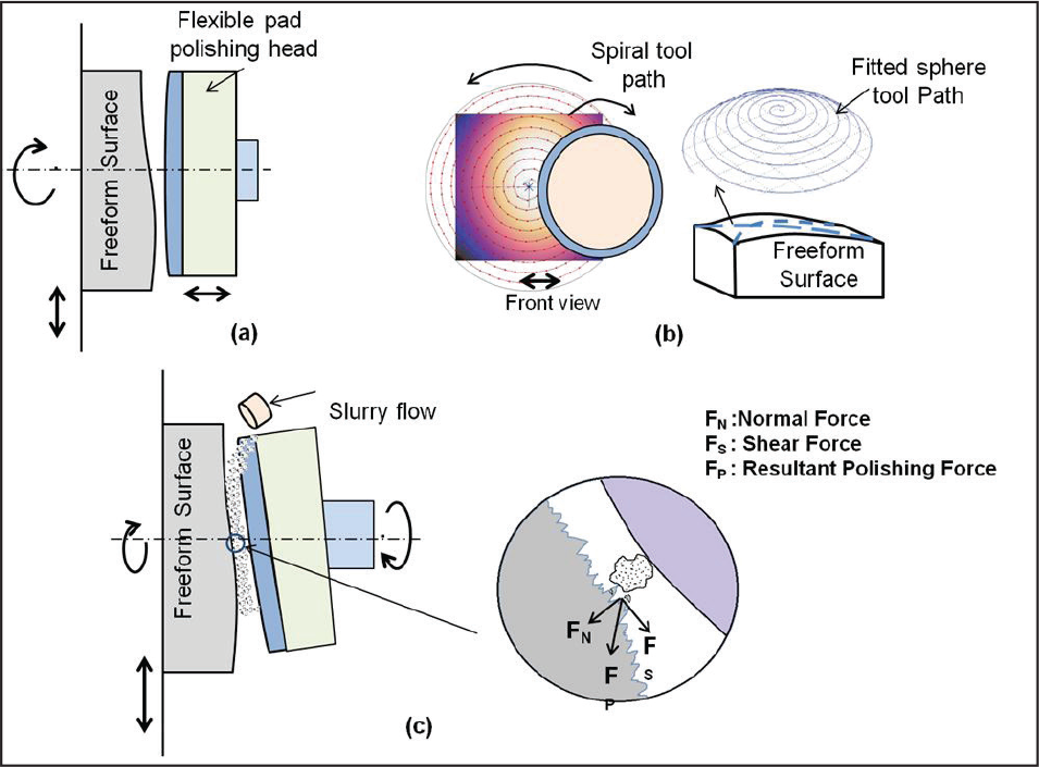
The schematic of the flexible pad polishing head and the freeform surface during the polishing process is shown in Figure 5. CeO2 abrasive particles are held between the rotating pad and the freeform surface. The polishing pressure is applied by moving the Z-axis toward the surface. Due to the application of pressure and the flexibility provided by the foam, the rubber pad has adopted the shape of the polishing zone. When the relative motion is provided to the surface and the polishing pad, the entrapped abrasive particle starts shearing the material. The amount of material removal depends on the polishing parameters, that is, rotational speed of the workpiece, abrasive flow rate, rotational speed of the polishing pad, polishing pad pressure, and feed rate of the polishing pad (conventionally called the polishing stroke). The resultant polishing force (FP) due to normal force (FN) applied by the polishing pad and the shear force (FS) between the flexible pad and the surface, is given by:
Steps involved in the generation of freeform surface.

The depth of penetration of the abrasive particle is decided by the FN and the shear force decides the surface material removal (Figure 5[c]). FN is kept constant throughout the polishing pressure by keeping the Z-axis positions constant. As per the Preston equation, the material removal mainly depends on the pressure (p) at the contact zone and the relative velocity (V) of the polishing pad and the workpiece and can be calculated as follows
33
:

where, k is the Preston constant, which depends upon the polishing conditions, that is, abrasive material, pad material, and slurry concentration, and ‘dz’ is the depth of material removal. The spindle with the workpiece is rotating with the speed (ωs). The flexible polishing pad is also rotating against the workpiece with speed (ωp). The relative velocity (V) at some point at distance r from the center of rotation can be calculated from the following equation 34 :
Flexible pad polishing motion and actions: (a) motions involved in flexible pad polishing; (b) polishing pad trajectory; and (c) polishing action and mechanism.

where e represents the center distance between the polishing pad and surface. The relative velocity at this point also depends upon transverse motion between the pad and the workpiece. In the current setup, the transverse motion is provided by providing feed (f) to the workpiece. The material removal for the flexible pad polishing can be calculated by applying/substituting the values of p and V (from Equations [3] and [7], respectively) in Equation (6).
Due to the complex shape of the freeform surface, the polishing pad needs to follow the surface profile to maintain uniform polishing pressure. This needs multi-axis platforms where it is possible to keep the tool always perpendicular to the surface with uniform pressure. As the currently developed setup is working on a two-axis platform, it is not possible to provide uniform polishing pressure throughout the surface. However, to minimize the pressure variation and to follow the surface profile closely during the polishing, the best fit sphere of the freeform surface is calculated and a spiral tool path as per the best fit sphere is generated to move the polishing pad over the surface, as shown in Figure 5(b). The majority of optical surfaces fall under the category of continuous shape. The developed setup is capable of polishing the low slope surfaces, which are continuous in nature. At present, the developed polishing setup is not suitable for polishing of the surfaces (a) having large slopes, (b) having large departure from the best fit sphere, and (c) having structured elements.
Results and discussion
Effects of polishing parameters
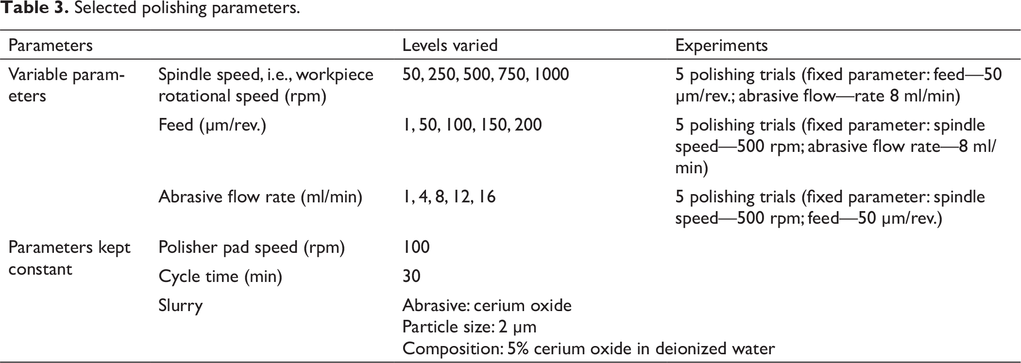
Preliminary experiments are performed to find the influence of flexible pad polishing parameters on the surface quality. Table 3 presents the polishing parameters and their levels used for the preliminary experiments. While one parameter is varying, the others are kept constant at their middle value.
The effect of each parameter is discussed comprehensively and the results are evaluated to identify the significant parameter for the better surface finish. After polishing, each surface is characterized with the help of a contact type mechanical profiler. In the current study, the goal is to improve the surface finish; hence, the average surface roughness (Ra) is chosen as a response parameter. Also, the Ra parameter provides average value of surface texture, and it is not possible to get information of any local scratches due to polishing. To verify this, Rt is also selected as response parameter.
Effects of spindle speed
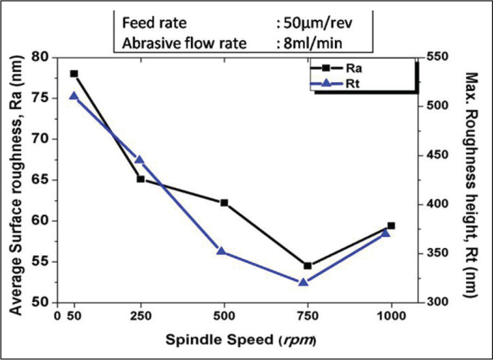
The influence of spindle speed surface roughness is studied. A series of experiments are conducted at different spindle speeds over the range of 50–1000 rpm as given in Table 3. Other parameters, that is, abrasive flow rate and feed rate, are set constant during polishing. Figure 6 shows the correlation between the surface finish and the spindle speed. Ra and Rt decrease with the increase in the spindle speed up to 750 rpm. However, with the further increase in the spindle speed, the roughness starts increasing. At low spindle speed, the hydrodynamic effect is not sufficient for efficient polishing. At high speed, that is, at 1000 rpm, the splashing of slurry is observed, which causes the poor slurry supply between the polishing pad and workpiece and results in degradation of the surface finish. It is expected that it occurs due to the polishing pad vibrations at high spindle speed.
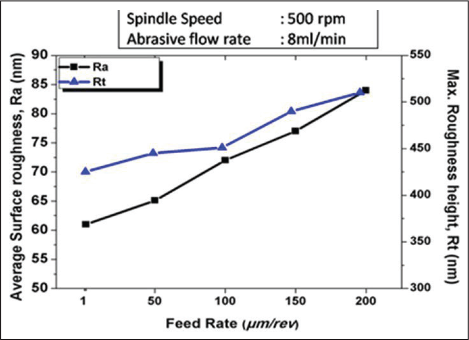
Effects of polishing feed rate
Selected polishing parameters.
Effect of spindle speed on Ra and Rt.
Effect of feed rate on Ra and Rt.
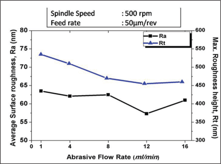
Effect of abrasive flow rate
Experiments are carried out to study the influence of the abrasive flow rate on the surface finish. The rate of abrasive flow at the polishing zone is controlled by a variable speed peristaltic pump. The abrasive flow rate is varied, ranging from 1 ml/min to 16 ml/min for experimentation. Figure 8 indicates the correlation between the abrasive flow rate and the surface finish. As the abrasive flow rate increases up to 12 ml/min, a large number of abrasives take part in polishing action, which results in an improvement in the surface finish in terms of lower Ra and Rt. On further increase of the abrasive flow rate, no improvement in the surface finish is observed. It is expected that an increase in the abrasive flow rate might result in the coagulation (viscosity increase) of slurry, which starts deteriorating the surface.
Effect of abrasive flow rate on Ra and Rt.
Optimization of flexible pad polishing parameters
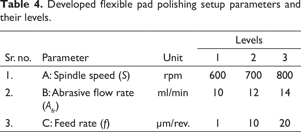
The experimental study to find out the effects of spindle speed (Figure 6), polishing feed rate (Figure 7), and abrasive flow rate (Figure 8) on surface roughness suggests the coarse range of parameters for achieving the minimum surface roughness. The spindle speed of 600–800 rpm, polishing feed rate of 1–10 µm/rev., and abrasive flow rate of 10–14 ml/min are the optimum parameters required to obtain minimum surface roughness. Further optimization of the polishing parameters is performed by conducting an experiment using the Taguchi design of L18 orthogonal array. Signal-to-noise ratio (S/N) graphs are drawn to identify the optimum level of parameters for polishing response characteristics. Table 4 contains the selected flexible pad polishing parameters and their levels for the experimental investigation.
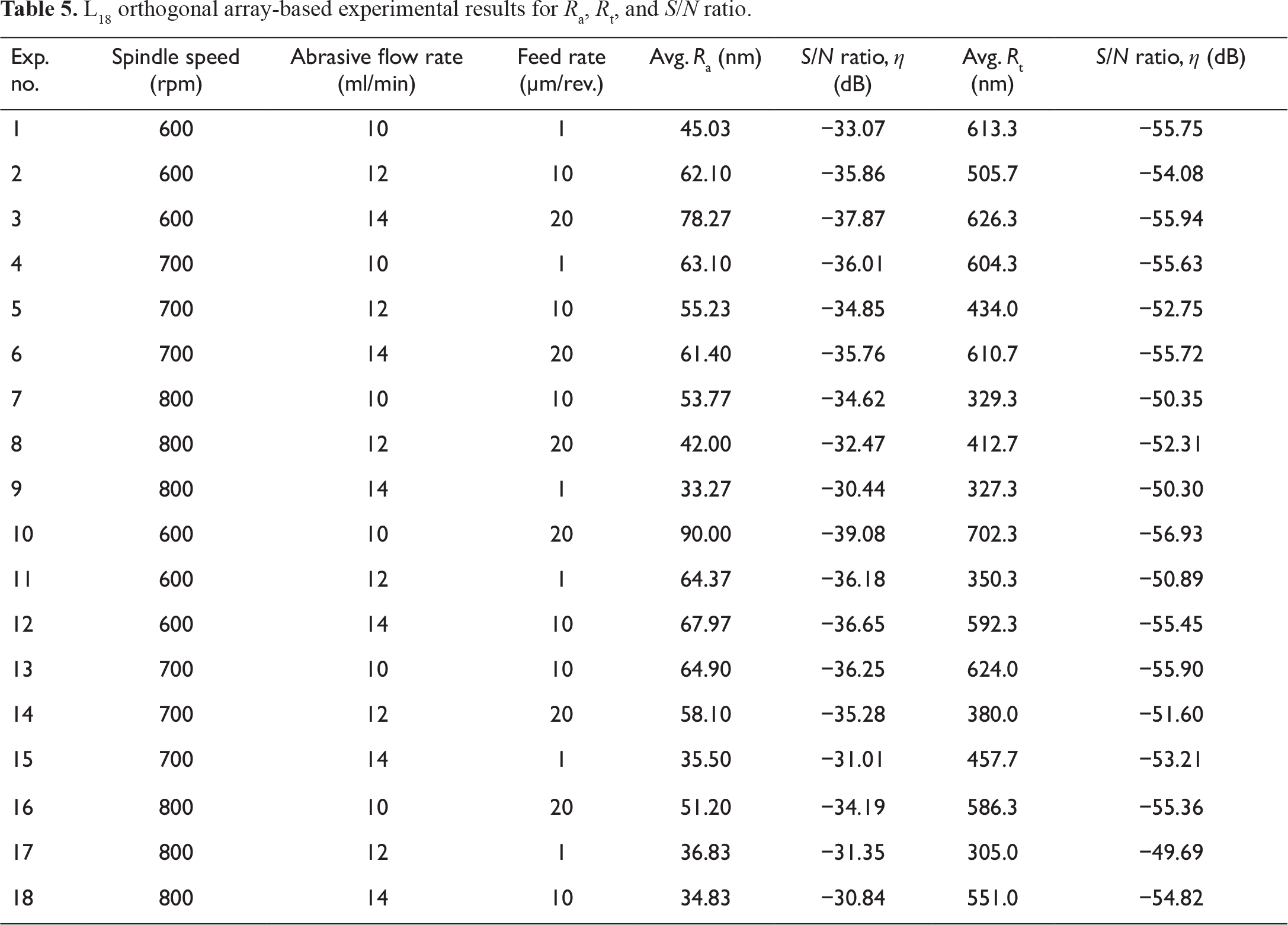
Table 5 represents the parameters, their setting values as per L18 orthogonal array, experimental results, and S/N ratio for surface roughness heights (Ra) and (Rt).
Developed flexible pad polishing setup parameters and their levels.
L18 orthogonal array-based experimental results for Ra, Rt, and S/N ratio.
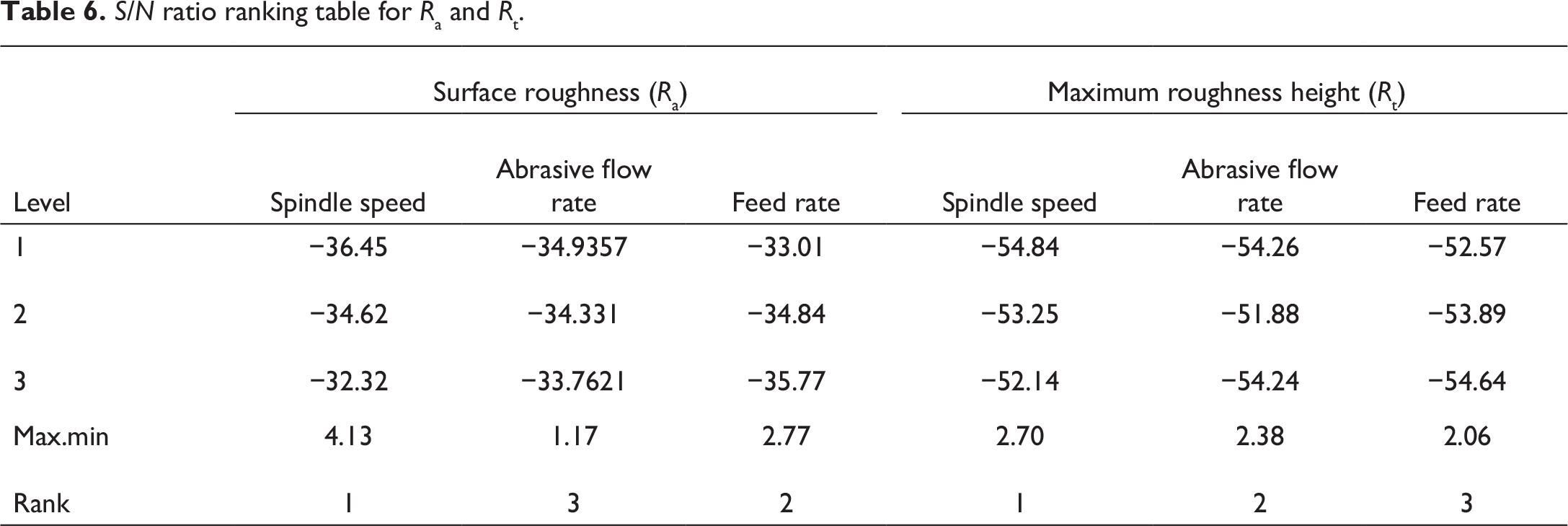
S/N ratio ranking table for Ra and Rt.
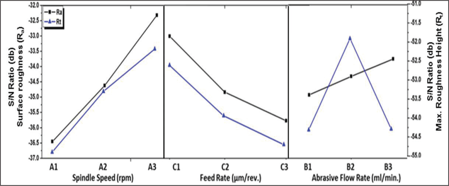
S/N ratio effect plots for flexible pad polishing experiments under varying polishing parameters.
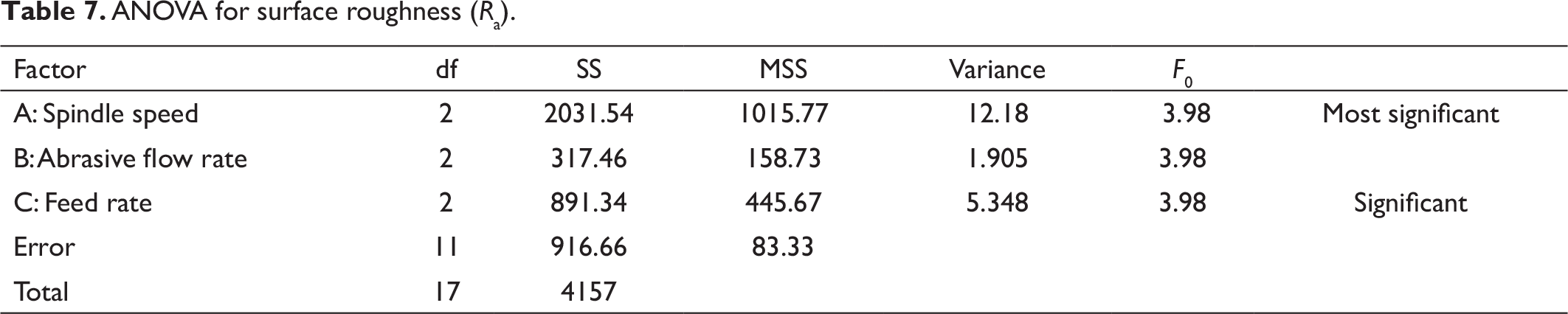
ANOVA for surface roughness (Ra).
ANOVA for maximum roughness height (Rt)
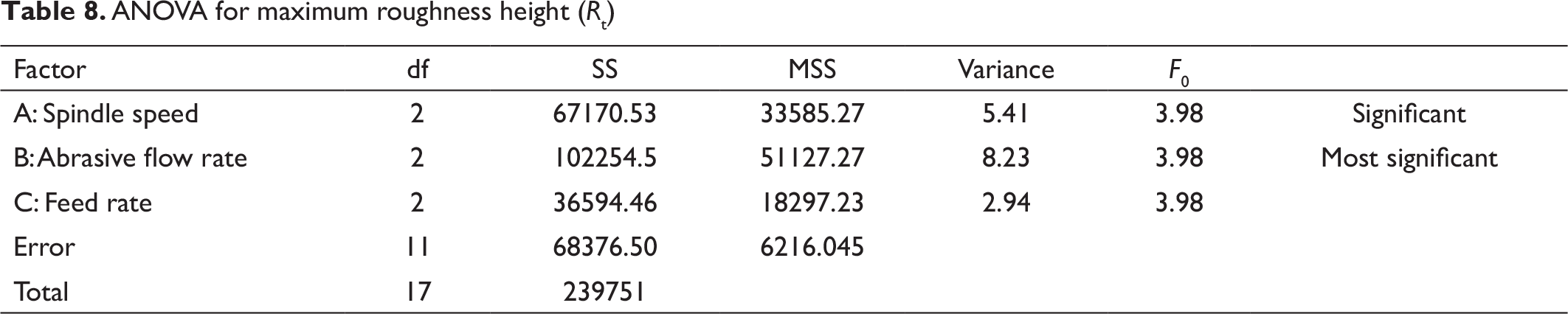
To find the significance of each parameter and to breakdown the variability of processes, ANOVA tables are constructed for Ra and Rt. From ANOVA (Table 7), it is identified that the spindle speed is the most significant parameter for average surface roughness (Ra) height. Feed rate is found as the second most important parameter. However, for the maximum surface roughness height (Rt), the abrasive flow rate is found to be the most important parameter followed by spindle speed (Table 8).
It is clear from ANOVA analysis (Figure 9) that the spindle speed is a significant factor for both Ra and Rt. The spindle speed is significant factor for both Ra and Rt. The speed of 800 rpm is optimum to create sufficient hydrodynamic pressure and effective utilization of slurry during the polishing process as compared to the selected lower values of the spindle speed. The abrasive flow rate has significant effect on Rt, but it is not significant for Ra. The abrasive flow rate decides the active abrasive particles for polishing by ensuring suitable slurry flow. The wrong selection of abrasive flow rate may lead to poor polishing action due to insufficient slurry or coagulation of abrasives if slurry supply is more. In both the conditions, there are chances of scratch marks on the surface. Hence, it is a significant factor for Rt compared to Ra, which is basically an average phenomenon. The optimized value of abrasive flow rate, that is, 12 ml/min, ensures that sufficient abrasive particles are involved in polishing action without any coagulation. Similarly, the optimal feed rate ensures the optimized dwell time on the polishing zone to remove the desired volume of the material. Results show that low feed rate (1 µm/rev.) provides better polishing action and hence improves in the surface finish. As the feed rate is directly related to polishing time, it is more significantly related to Ra compared to Rt.
Constants and coefficients for the developed mathematical equation to predict Ra.

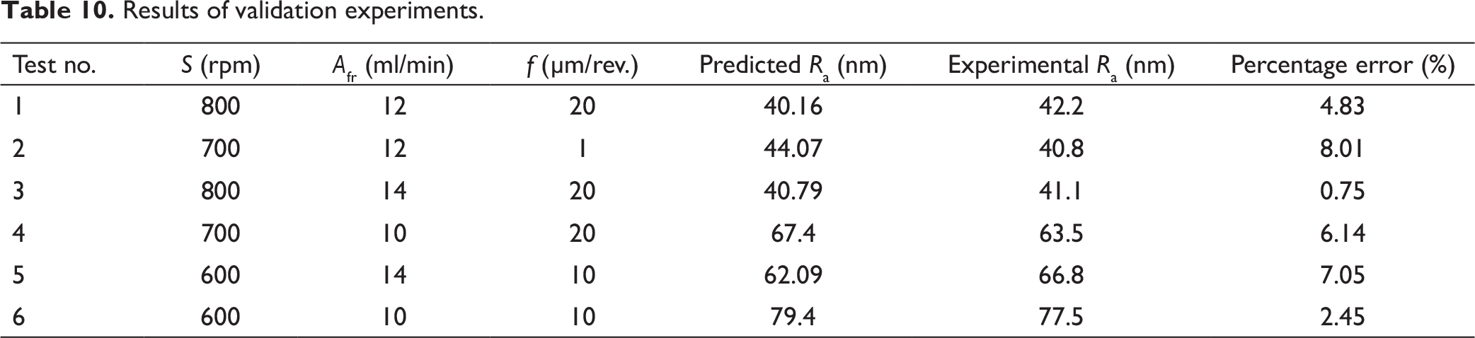
Results of validation experiments.
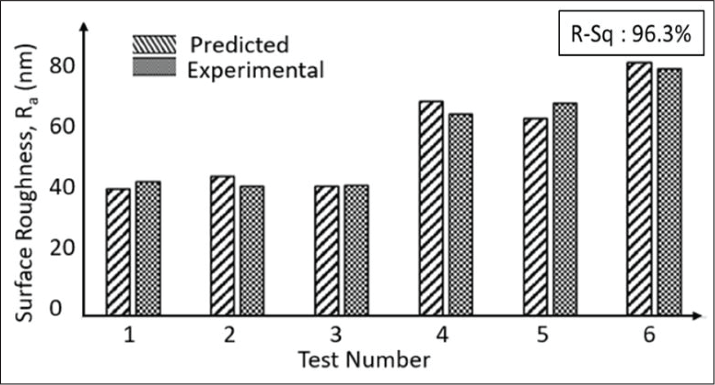
Validation results for the developed mathematical model for average surface roughness.
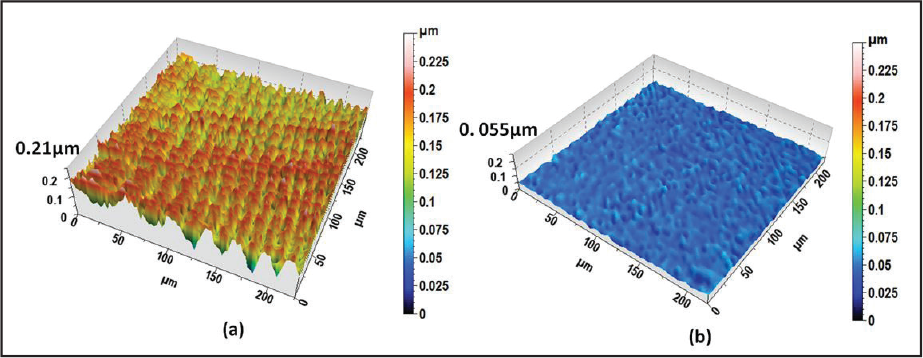
where S is spindle speed, f is feed rate and Afr is the abrasive flow rate, c is constant, and a1, …, a9 are the coefficients of the developed mathematical equation. The values of the coefficients and constant for Equation (8) are given in Table 9. The developed mathematical model can be used to set the flexible pad polishing parameter in advance and predict the surface roughness.
To validate the developed model, the validity tests are carried out and compared with the predicted results. The experimental conditions and the outcome of the validation experiments are given in Table 10. The comparison of the predicted and the experimental results are presented in Figure 10. The experimental results are found to be in good agreement with the predicted values calculated based on the developed model (R-Sq: 96.3%).
As surface roughness and the profile error are the main parameters to measure the quality of optical surfaces, further analysis is done to verify the effect of polishing on these response parameters.
Analysis of surface finish
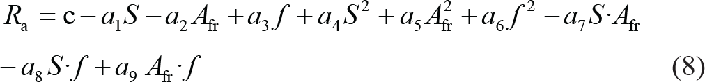
To demonstrate the effectiveness of the developed flexible pad polishing process, the surface roughness of the freeform surface is compared before and after the polishing. Surface roughness heights of the surfaces are characterized by a mechanical profiler. The Ra value of the unpolished freeform surface is 220 nm. However, after 30 min of continuous polishing, it has reduced to 25 nm as shown in Figure 11.
Further, to explore the effect of polishing on the surface texture, 3D surface scans are taken with the help of an optical profiler. It can be observed from Figure 12 that the peaks and irregularities which were present before the polishing are completely removed after polishing and a smooth surface is achieved.
Surface roughness plots: (a) surface roughness before polishing and (b) surface roughness after polishing.
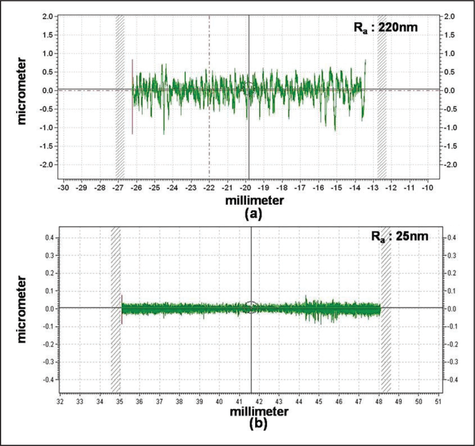
Measured 3D surface topology: (a) unpolished surface and (b) polished surface.
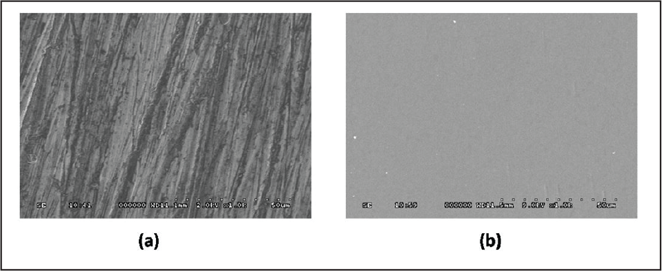
The polished surfaces are also analyzed with SEM. Figure 13 shows the SEM images with the magnification of 1000× of the unpolished and polished freeform surface. Substantial improvement is observed on the surface quality after polishing the specimens on the developed polishing setup. There are many scratch marks and tool marks present on the workpiece before the polishing. After the polishing, the surface finish is improved and the surface is free from scratches and tool marks. SEM images for surface finishing analysis also prove the effectiveness of the polishing setup.
SEM images of surface: (a) before polishing and (b) after polishing.
Analysis of surface finish variation and form error
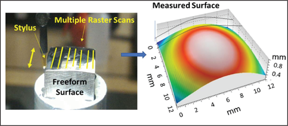
As discussed in the previous section, a significant improvement is achieved on the surface finish after polishing the freeform surface on a flexible pad polishing setup. Although, the surface Ra is minimized from 220 nm to 25 nm in 30 min of polishing, the evaluation of the surface roughness at different regions of the surface and evaluation of freeform shape error is an equally important factor. To find out the effects of the developed polishing process on the surface profile and the variation of surface finish throughout the surface, the freeform surface is characterized by pre- and post-polishing. For the initial surface (unpolished), a detailed zone-wise analysis of surface roughness is not performed. It is assumed that the surface roughness due to milling is completely removed during polishing and only the effects due to the polishing process remain on the surface. Hence, the average values are used for analysis. For polished surface characterization, 12 raster scans are taken using a contact-type profiler to evaluate the 12 mm2 area of the freeform sample as shown in Figure 14. All the raster scans are stitched together to get the 3D surface. 35
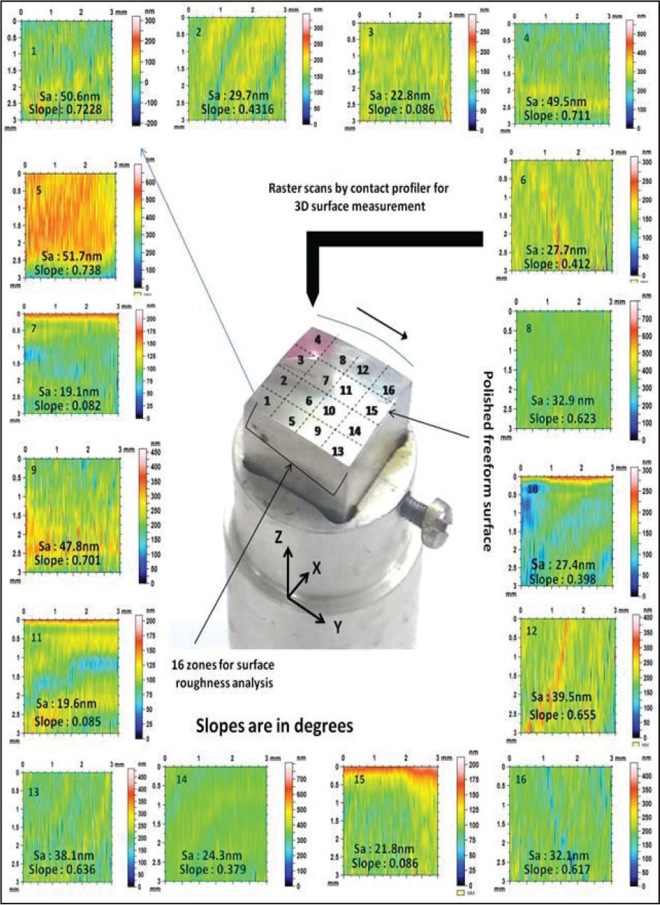
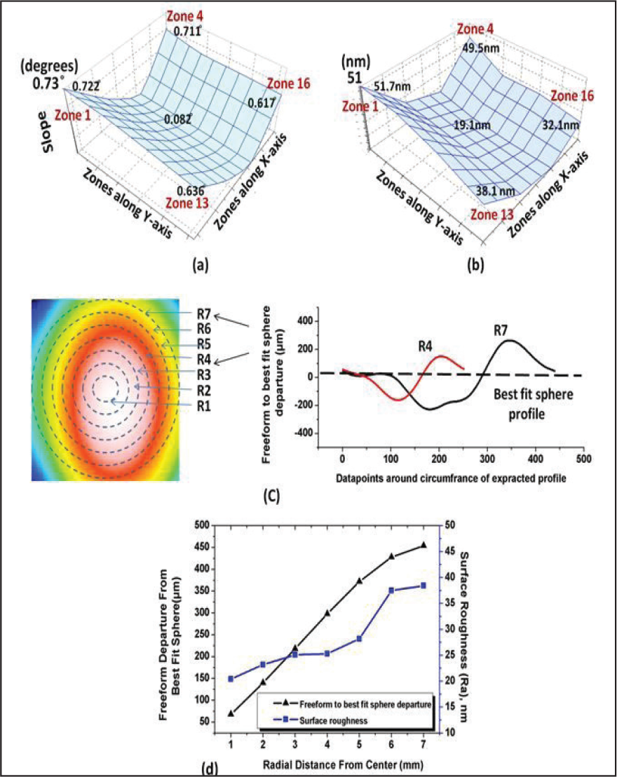
As discussed earlier, due to the use of a two-axis configuration, it is difficult to maintain uniform polishing pressure throughout the surface. The variation in surface roughness on the freeform surface is studied by dividing the surface area into 16 zones. The theoretical slope of each zone is calculated and 3D surface roughness of each zone is obtained from the measured surface as displayed in Figure 15. To verify the deviation of surface roughness concerning the slope, the slope values and the respective roughness are plotted, as presented in Figures 16(a) and (b), respectively. It is observed from the trends of the plots, slope, and roughness values given in Figure 15 that the larger the slope on the surface the higher is the surface roughness. The variation in polishing pressure depends upon the slope variation and the departure of the tool travel path from the exact freeform profile. To check the variation of roughness for the departure of the spherical tool path and the freeform profile, 2D profiles are extracted from seven different locations of the freeform profile, as shown in Figure 16(c). The extracted profiles are compared with the tool path profile, that is, best fit sphere profile, at the same locations and the departures are calculated. The departures and surface roughness from the extracted profiles are demonstrated in Figure 16(d). The results signify that the surface roughness is high near to the edges where the departure of the tool path and the designed profile is high. The surface roughness is less near to the center as the departure of the freeform profile and tool path is less and, therefore, the polishing pressure is more uniform. The surface roughness variation is from 19 nm to 50.6 nm on the surface.
Schematic of the freeform surface measurement by the mechanical profiler.
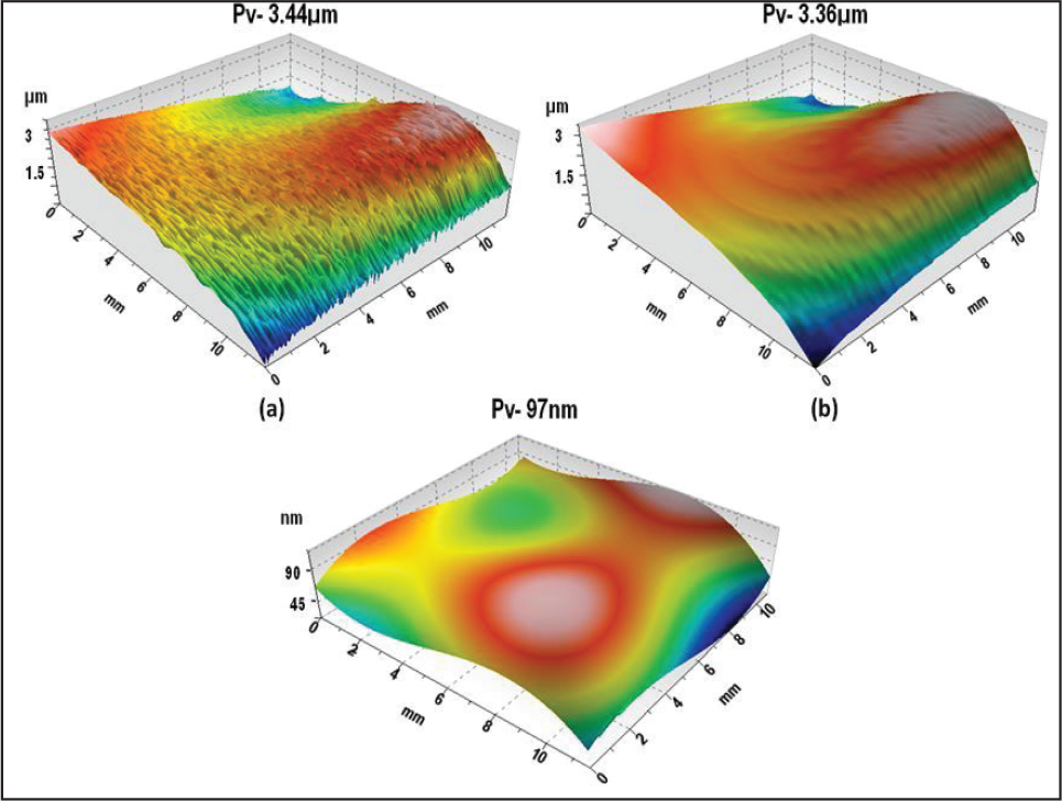
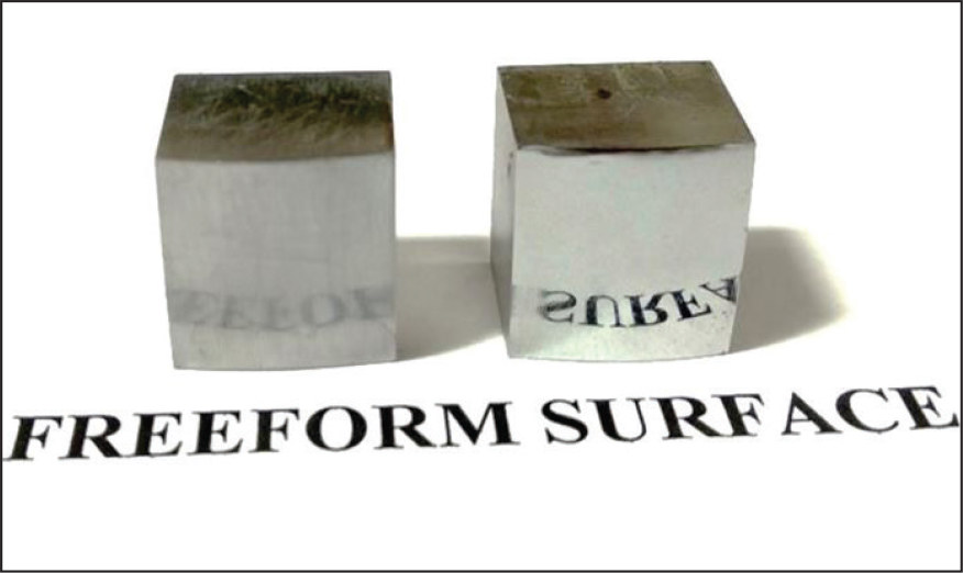
Further, the measured surfaces are compared with the designed surface to know the profile error. Ideally, the polishing process should not affect the profile of the optics while improving the surface finish. The designed shape is compared with the stitched 3D shape. The residual profile error (Pv) after milling operation is 3.44 μm as shown in Figure 17(a). The surface is again characterized after polishing and the profile-to-valley error is of 3.36 µm, as displayed in Figure 17(b). Both the profiles’ post-milling and post-polishing are compared to verify the change in the profile during polishing. The surface roughness (high-frequency undulations) is filtered from the measured profile to get the exact change in shape. The comparison shows that the change in profile due to polishing operation is only 97 nm (Figure 17[c]), which is quite encouraging and shows the capability of developed polishing setup for nano-finishing freeform optical surfaces. The actual picture of the polished freeform steel mold is shown in Figure 18.
Zone-wise analysis of surface roughness.
Surface roughness analysis with respect to the slope: (a) zone-wise slope variation; (b) zone-wise surface roughness variation; (c) 2D profile extraction from different radial distance from center and comparison with tool path; and (d) variation of surface roughness due to departure of the profile from tool path.
Form error analysis: (a) surface roughness before polishing; (b) surface roughness after polishing; and (c) change in the profile of freeform surface due to flexible pad polishing.
Conclusions
A nano-finishing process for the polishing of freeform optics mold using a flexible pad is developed. For precise motion requirements, the developed setup is integrated with a two-axis diamond turning machine. The flexible nature of the polishing pad and precise machine motions of the diamond turning machine are utilized to improve the surface finish and to maintain the profile of the freeform surface.
Actual photo of polished freeform mold.
The influence of the developed polishing parameters on surface quality is studied experimentally. The optimum parametric combination for the better surface finish on freeform optics for the developed flexible pad polishing setup is investigated. Spindle speed of 800 rpm, abrasive flow rate of 12 ml/min and feed rate of 1 µm/rev. are found to be the optimum combination. The surface roughness of freeform optics mold is reduced from 220 nm to 25 nm while polishing with the optimized parameters for 30 min. The initial surface roughness value of 220 nm was the average surface roughness of the milled surface.
Flexible pad polishing process is an effective method to carry out the nano-finishing of the freeform optics without disturbing the already achieved profile. A small change of 97 nm is observed in the shape of the freeform surface during the polishing.
The current polishing method can also be utilized for removing the tool marks from the diamond turned components and also for polishing of aspheric, spherical, and flat surfaces in situ. In the future, this process can be extended for corrective polishing to improve the profile of freeform surfaces.
Footnotes
Declaration of conflicting interests
The authors declared no potential conflicts of interest with respect to the research, authorship, and/or publication of this article.
Funding
The authors received no financial support for the research, authorship, and/or publication of this article.